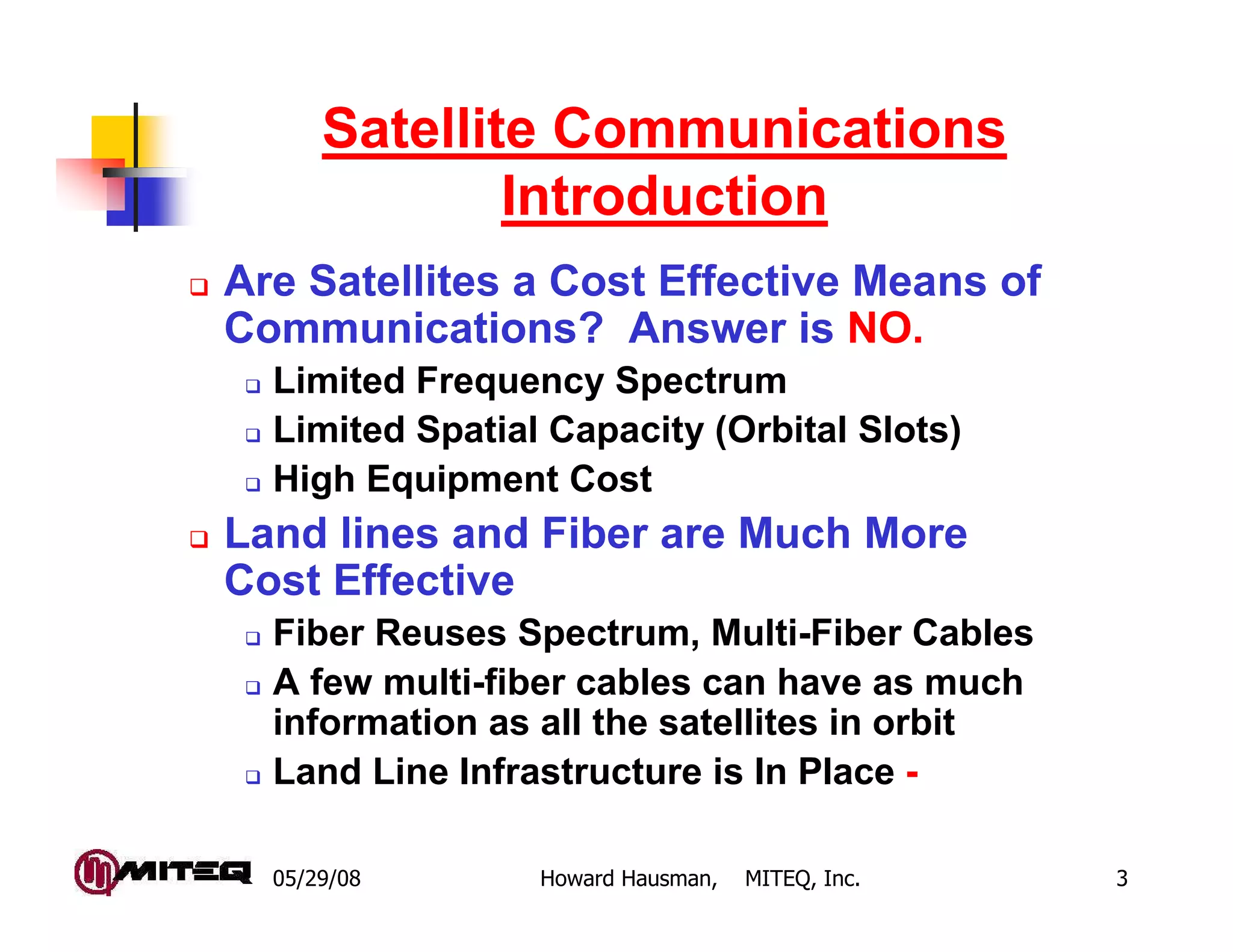
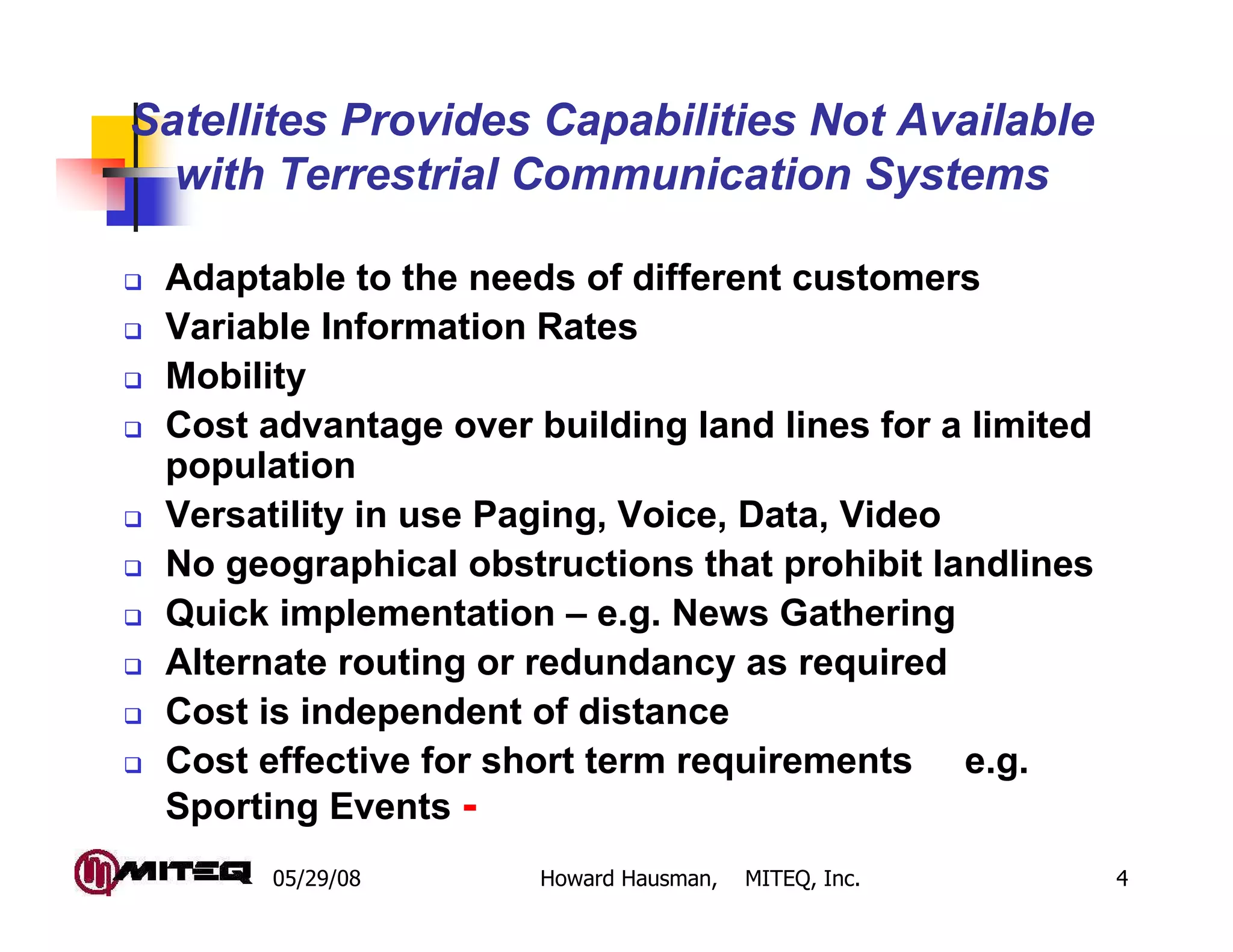
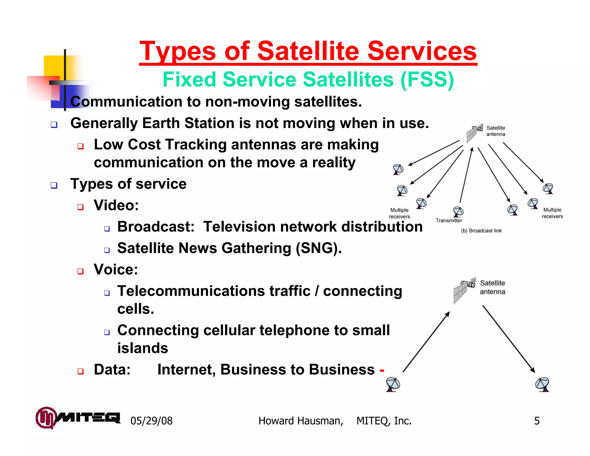
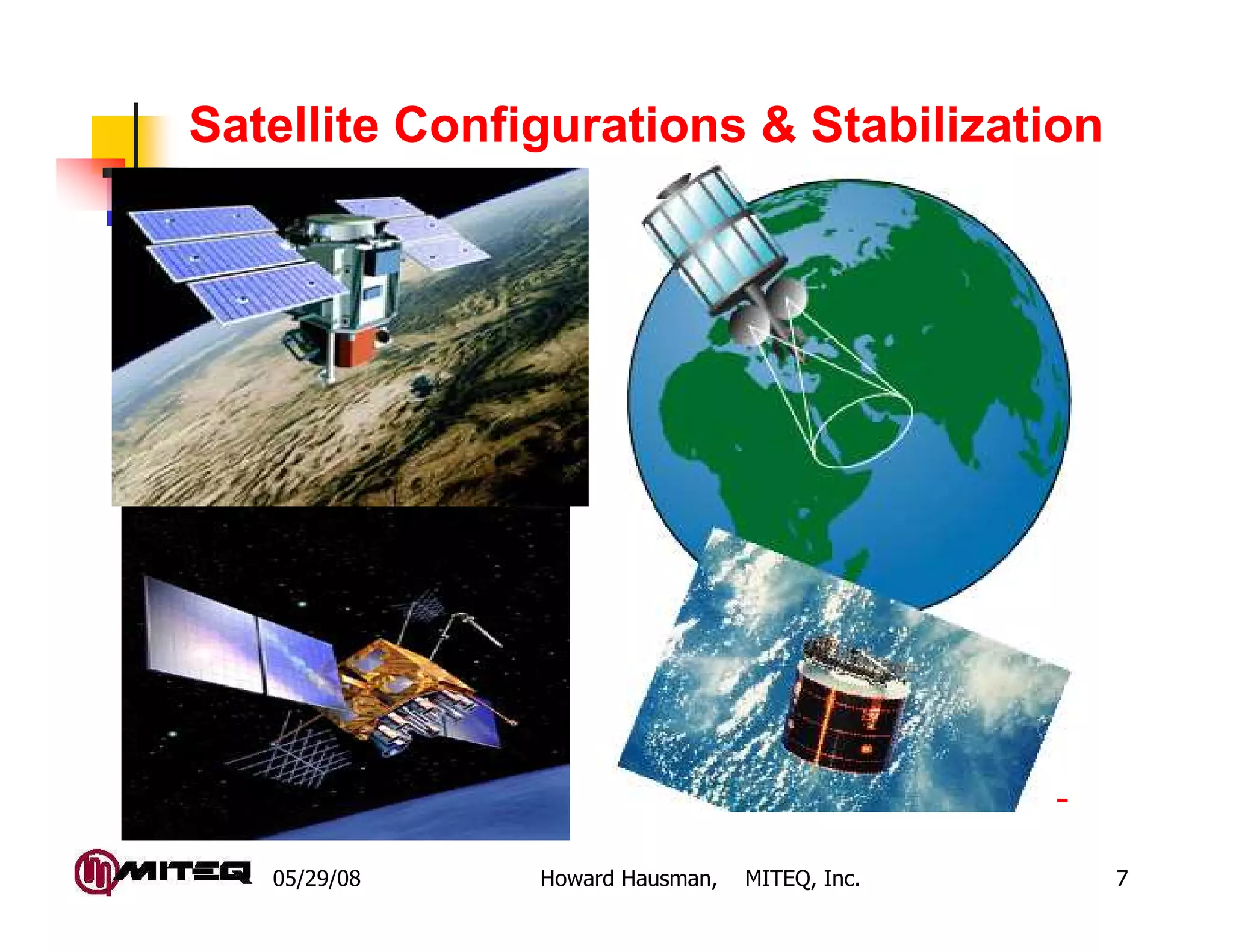
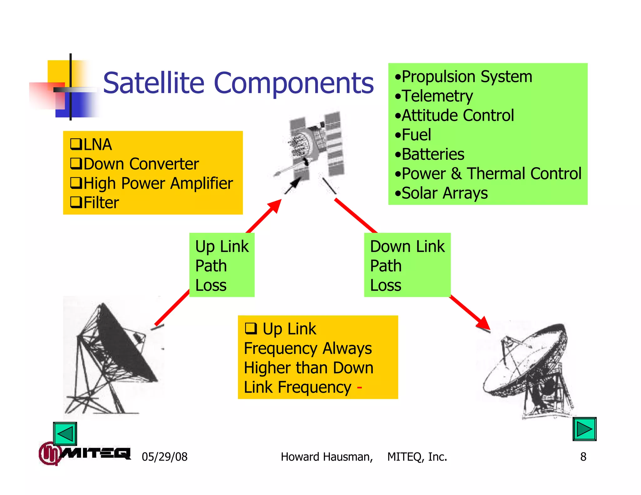
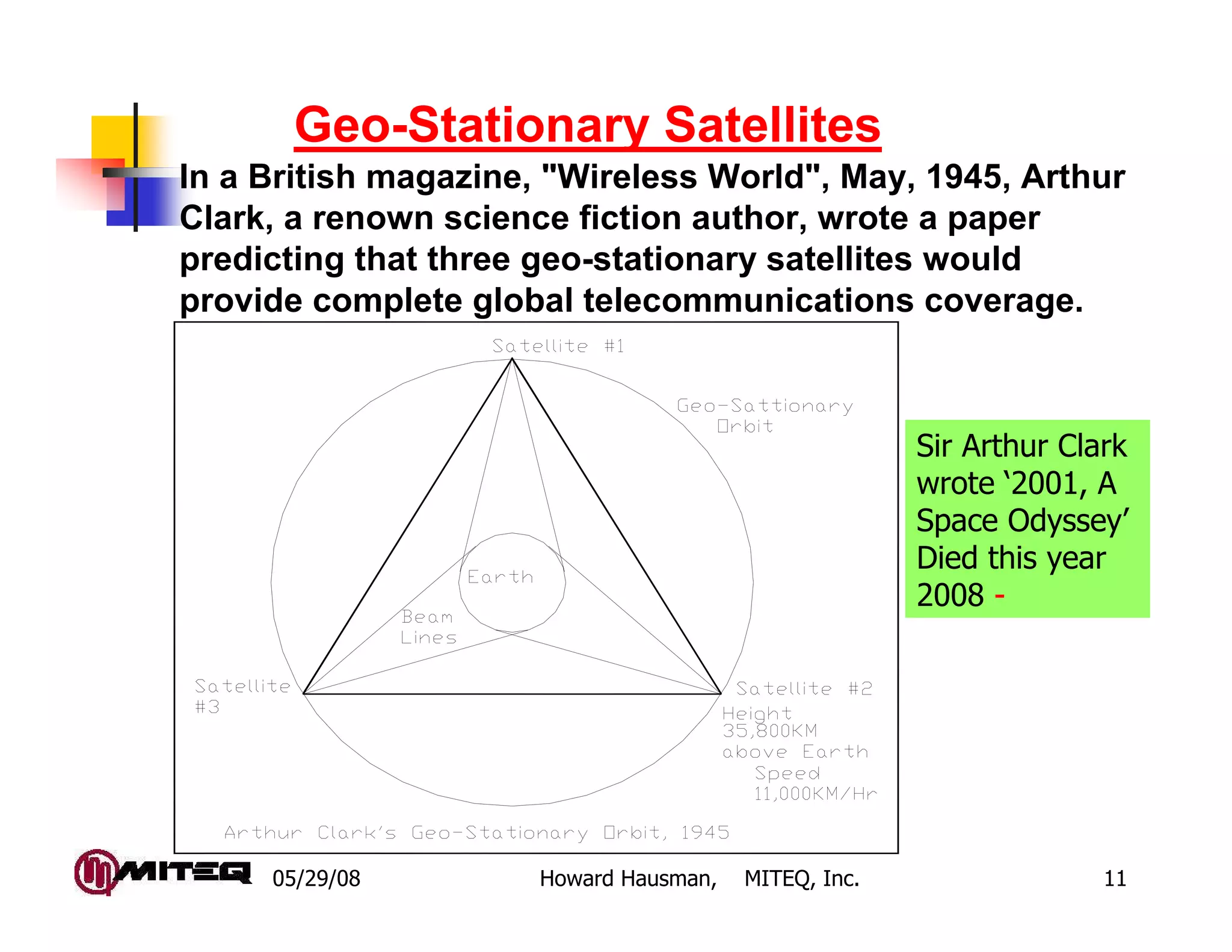
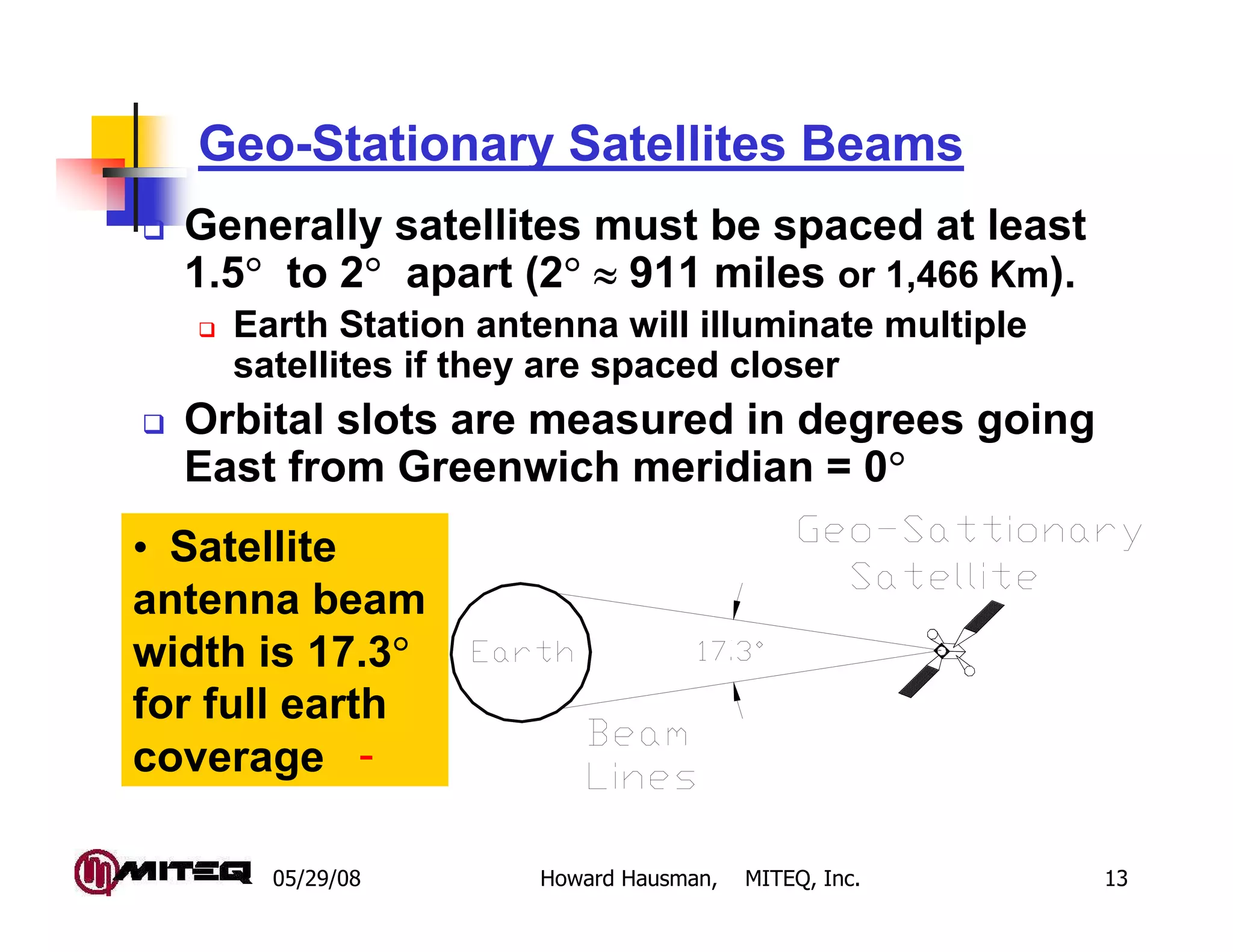
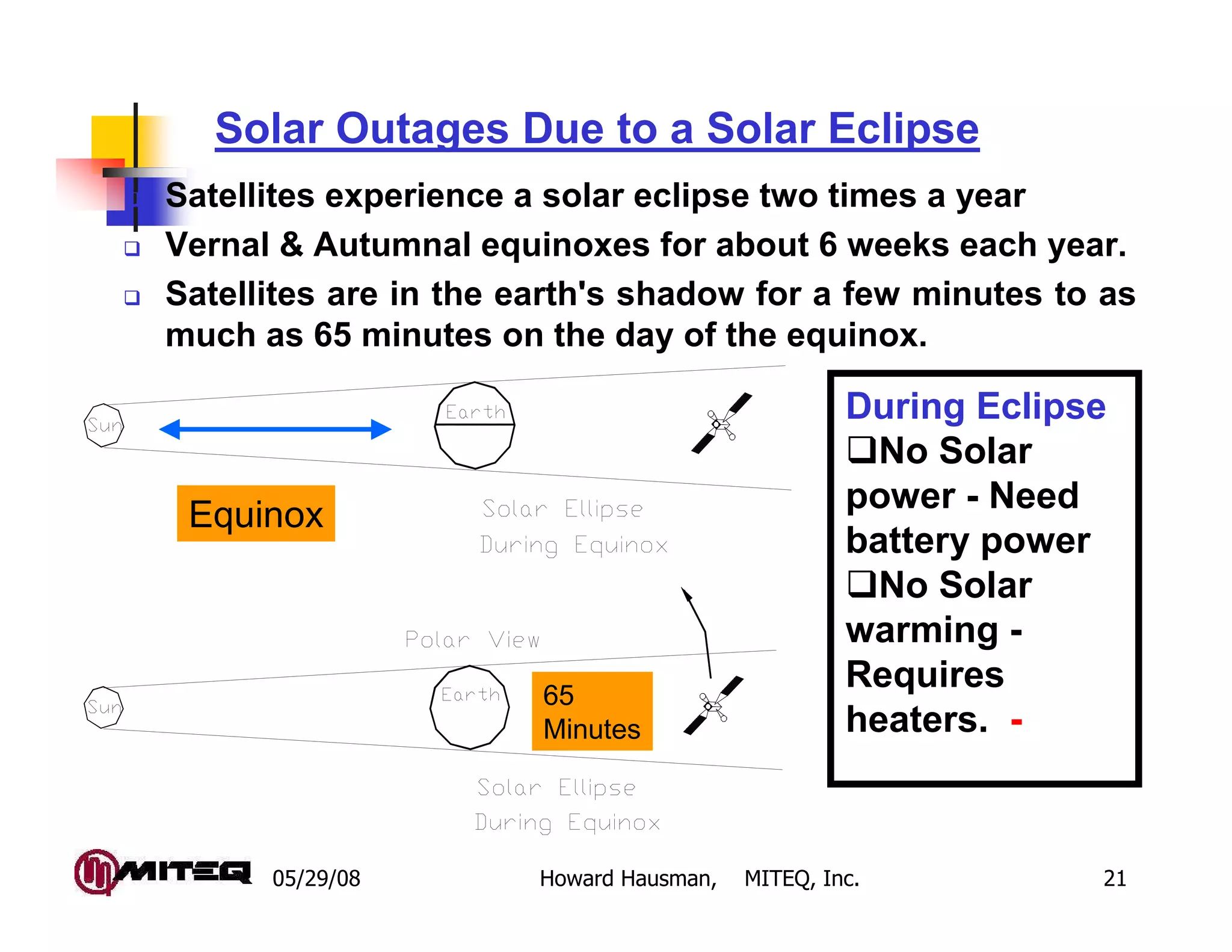
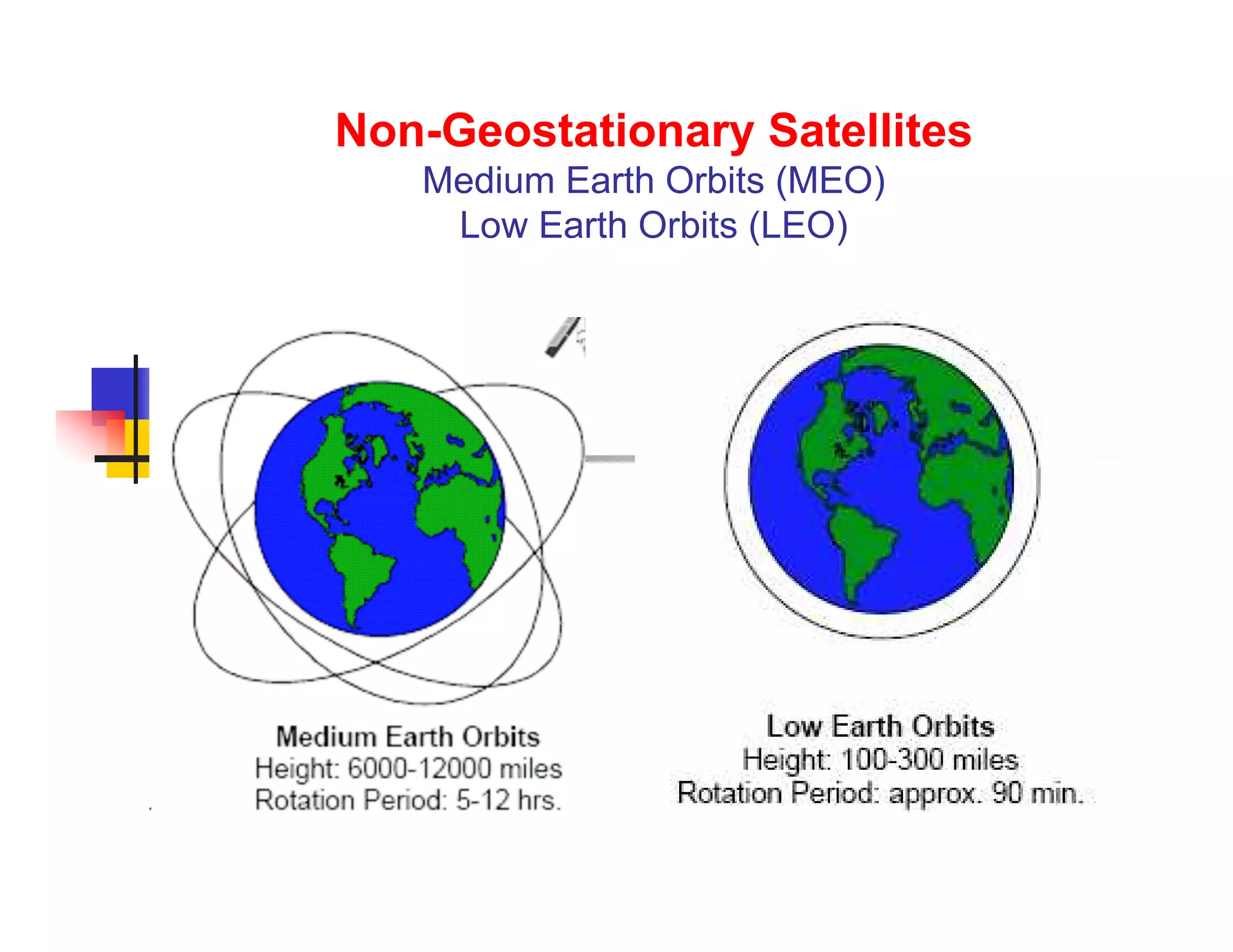
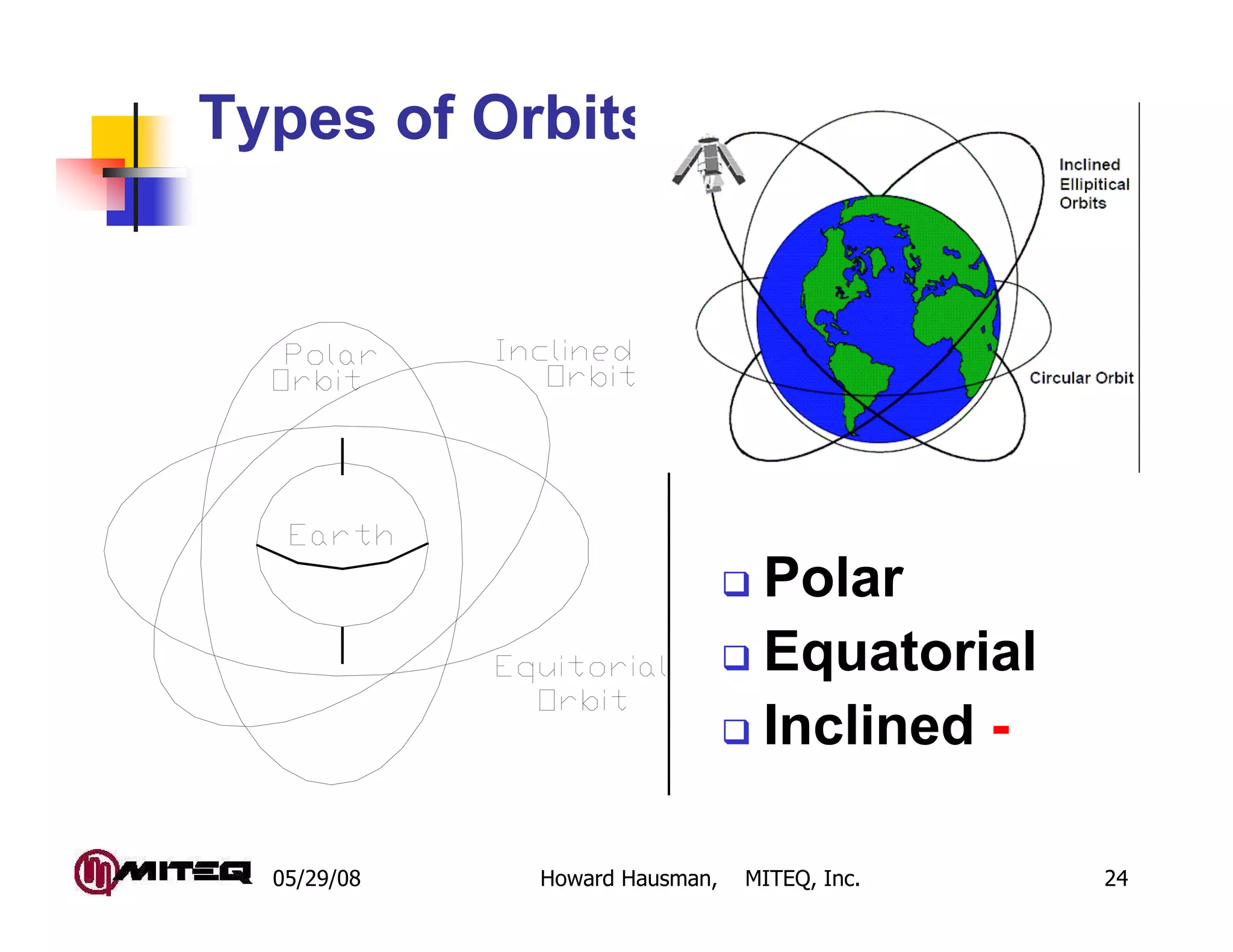
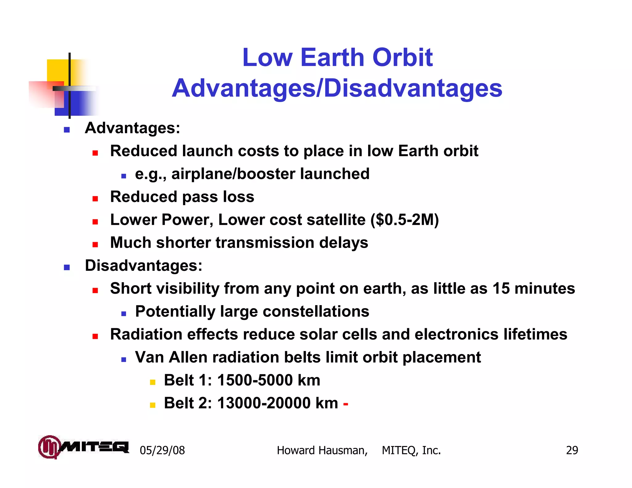
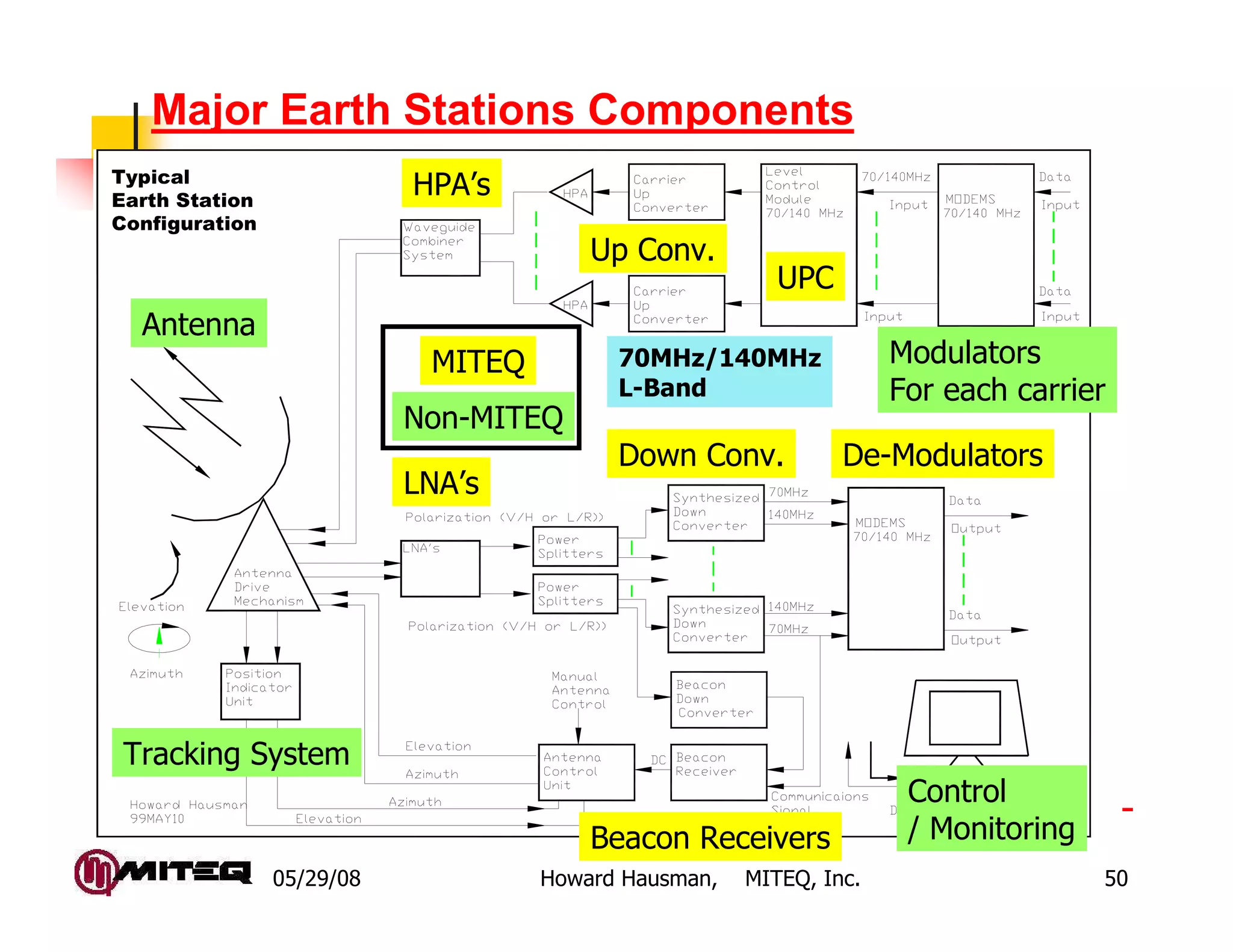
SlideShare a Scribd company logo
1 of 51
Download to read offline
Fundamentals of Satellite
Communications, Part 1
Howard Hausman
President
MITEQ, Inc.
Hauppauge, NY 11788
May 29, 2008
05/29/08 Howard Hausman, MITEQ, Inc. 2
Fundamentals of Satellite
Communications Part 1
Satellite Communications Introduction
Types of Satellite Services
Satellite Configurations
Geostationary Satellites
Non-Geostationary Satellites
Satellite Configurations
Frequency Reuse / Polarization
Earth Station Antennas
Major Earth Stations Components
Satellite Communications Summary
Part 2 – Communication System Link Analysis
Part 3 – Specifying Subsystems for Data
Communications -
05/29/08 Howard Hausman, MITEQ, Inc. 3
Satellite Communications
Introduction
Are Satellites a Cost Effective Means of
Communications? Answer is NO.
Limited Frequency Spectrum
Limited Spatial Capacity (Orbital Slots)
High Equipment Cost
Land lines and Fiber are Much More
Cost Effective
Fiber Reuses Spectrum, Multi-Fiber Cables
A few multi-fiber cables can have as much
information as all the satellites in orbit
Land Line Infrastructure is In Place -
05/29/08 Howard Hausman, MITEQ, Inc. 4
Adaptable to the needs of different customers
Variable Information Rates
Mobility
Cost advantage over building land lines for a limited
population
Versatility in use Paging, Voice, Data, Video
No geographical obstructions that prohibit landlines
Quick implementation – e.g. News Gathering
Alternate routing or redundancy as required
Cost is independent of distance
Cost effective for short term requirements e.g.
Sporting Events -
Satellites Provides Capabilities Not Available
with Terrestrial Communication Systems
05/29/08 Howard Hausman, MITEQ, Inc. 5
Types of Satellite Services
Fixed Service Satellites (FSS)
Communication to non-moving satellites.
Generally Earth Station is not moving when in use.
Low Cost Tracking antennas are making
communication on the move a reality
Types of service
Video:
Broadcast: Television network distribution
Satellite News Gathering (SNG).
Voice:
Telecommunications traffic / connecting
cells.
Connecting cellular telephone to small
islands
Data: Internet, Business to Business -
05/29/08 Howard Hausman, MITEQ, Inc. 6
Satellite Industry Issues and Concerns
Frequency spectrum
Orbital Slots
Regulatory inconsistencies
Signals reach multiple countries
Consolidation of manufacturers
Multiple standards
Quality control versus production lead time
Rapid change in telecommunications
requirements
Digital Television
Rapid deployment of Fiber optics -
05/29/08 Howard Hausman, MITEQ, Inc. 7
Satellite Configurations & Stabilization
-
05/29/08 Howard Hausman, MITEQ, Inc. 8
Satellite Components •Propulsion System
•Telemetry
•Attitude Control
•Fuel
•Batteries
•Power & Thermal Control
•Solar Arrays
LNA
Down Converter
High Power Amplifier
Filter
Up Link
Path
Loss
Down Link
Path
Loss
Up Link
Frequency Always
Higher than Down
Link Frequency -
05/29/08 Howard Hausman, MITEQ, Inc. 9
Spin Stabilized Satellites
Satellite Body is Spin
Stabilized (60-100 RPM)
Gyroscopic stability
Spins to minimize thermal
effects
1/2 the solar cells face the
sun at one time
More efficient for smaller
satellites
Antenna must de-spun -
Spin
Stabilized
05/29/08 Howard Hausman, MITEQ, Inc. 10
Body Stabilized Satellites
All solar cells face the
sun
Thermal control more
difficult
Requires more
stabilization control
More solar cells than
Spin Stabilized Satellites
Better design for larger
satellites -
Body Stabilized
05/29/08 Howard Hausman, MITEQ, Inc. 11
Geo-Stationary Satellites
In a British magazine, "Wireless World", May, 1945, Arthur
Clark, a renown science fiction author, wrote a paper
predicting that three geo-stationary satellites would
provide complete global telecommunications coverage.
Sir Arthur Clark
wrote ‘2001, A
Space Odyssey’
Died this year
2008 -
05/29/08 Howard Hausman, MITEQ, Inc. 12
Geo-Stationary Satellites (Continued)
Clark Orbit, which is Equatorial Circular
35,800km (22,300 Miles ) above the Earth traveling
at a speed of 11,000km/hour
One Orbit takes 24 hours
Synchronous with the spinning of the Earth
Satellites headed for geosynchronous orbit first go
to a Geostationary Transfer Orbit (GTO)
Elliptical orbit with apogee about 23,000 miles.
Firing the rocket engines at apogee then makes the
orbit circular.
A Single Satellite is visible from ≈≈≈≈ 1/3 of the earth's
surface, excluding extreme Polar Regions.
Cannot see latitudes greater than ±±±± 77°°°°
Orbital locations are regulated by the International
telecommunications Union (ITU) -
05/29/08 Howard Hausman, MITEQ, Inc. 13
Geo-Stationary Satellites Beams
Generally satellites must be spaced at least
1.5°°°° to 2°°°° apart (2°°°° ≈≈≈≈ 911 miles or 1,466 Km).
Earth Station antenna will illuminate multiple
satellites if they are spaced closer
Orbital slots are measured in degrees going
East from Greenwich meridian = 0°°°°
• Satellite
antenna beam
width is 17.3°°°°
for full earth
coverage -
05/29/08 Howard Hausman, MITEQ, Inc. 14
Advantages/Disadvantages
of Geo-Synchronous Orbits
Advantages:
No ground station tracking required
No inter-satellite handoff, permanently in view
Three satellites give full earth coverage
Almost no Doppler shift, yields reduced complexity
receivers
Disadvantages:
35786 km orbits imply long transmission latencies
Weak received signal
Poor coverage at high latitudes (>77 degrees) -
05/29/08 Howard Hausman, MITEQ, Inc. 15
Satellite Link Delays
Satellite to the surface of the Earth is 22,300 miles
Two way transmission is 44,600 miles
C = speed of light = 186,282 miles per second
239 milliseconds Minimum
delay
Transmit and receive
stations on the equator at
the same longitude as
the satellite.
Typical signals may required
two hops through the
satellite, i.e. around
500mSec
500mS echo is barely
distinguishable -
>120 ms
>120 ms
120 ms
05/29/08 Howard Hausman, MITEQ, Inc. 16
Elevation & Slant-Range
Not All Satellites are located above the Earth Station
At Higher Elevation Angles
Signals Traverse Less Atmosphere
Overall Slant-Range is Reduced.
Signal Strength is Inversely Proportional to the Square of
the Distance
Atmospheric Effects are Significant at Low elevation
Note the difference
in traversed
atmosphere -
Top of the Atmosphere
05/29/08 Howard Hausman, MITEQ, Inc. 17
Elevation Angles & Atmospheric Effects
Minimum Elevation Angles
C-Band Elevations ≥≥≥≥ 5°°°°
Ku-Band Elevations ≥≥≥≥ 10°°°°
Low
Elevation
Angle
High
Elevation
Angle
Atmospheric Effects are
critical to signal path Loss
22,300 miles Earth to
Satellite
1st 5 miles is most critical
> 5 miles at low angles of
elevation
Atmospheric Problems
Potential interference
from terrestrial sources.
Increased atmospheric
absorption
Partially depolarizes
signal -
05/29/08 Howard Hausman, MITEQ, Inc. 18
Geo-Stationary Satellite Movement
North-South perturbations
Due to gravitational pulls of the Sun and Moon (Similar
to Tidal Effects)
North-South perturbations are the largest
Most demanding on satellite fuel reserves
East-West perturbations
Due to lumpiness of the Earth
Incorrect satellite velocity & altitude -
North-South East-West
05/29/08 Howard Hausman, MITEQ, Inc. 19
North-South Satellite Movement
An Object not exactly over the equator, transcribes a figure
eight pattern to an observer on Earth
Satellite lateral errors can be as much as ±±±± 3 °°°° at end of life
Looks like an up and down motion two times every 24
hours
Large Earth Station Antennas must track the motion -
05/29/08 Howard Hausman, MITEQ, Inc. 20
Satellite Orbit Stabilization & Life
Positioning is regularly corrected to within ±±±± 0.1°°°°
Without correction the movement in the North-South
direction will be about 0.85 °°°° per year
±±±± 15°°°° over the satellites typical 12 year lifetime
Life of satellite is determined by how much fuel is stored to
correct its position
Last remaining fuel is used to move the satellite out of
orbit
Satellite fuel capacity is typically designed for 13 years,
because the satellite technology becomes obsolete.
Satellite life can be extended by making less frequent
position corrections
Allowing ±±±± 3°°°° latitude shift can extend the satellite life as
much as 3 years. -
05/29/08 Howard Hausman, MITEQ, Inc. 21
Solar Outages Due to a Solar Eclipse
Satellites experience a solar eclipse two times a year
Vernal & Autumnal equinoxes for about 6 weeks each year.
Satellites are in the earth's shadow for a few minutes to as
much as 65 minutes on the day of the equinox.
During Eclipse
No Solar
power - Need
battery power
No Solar
warming -
Requires
heaters. -
Equinox
65
Minutes
05/29/08 Howard Hausman, MITEQ, Inc. 22
Satellite Eclipse of the sun
For about five days during the eclipse season (65
days) the sun passes behind the satellite with respect
to the earth station.
The background noise builds up as this event unfolds
Plateaus for about 10 minutes.
The satellite may be unusable (due to lower C/N) for
this period
Traffic may have to be switched to another satellite.
Outage occurs around noon
Larger diameter receive antennas (small beam width) exhibit
this a shorter time and fewer days
Tracking: mode is
usually turned off to
prevent the Earth Station
from the tracking the Sun,
which at this time is a
higher source of energy. -
Non-Geostationary Satellites
Medium Earth Orbits (MEO)
Low Earth Orbits (LEO)
05/29/08 Howard Hausman, MITEQ, Inc. 24
Types of Orbits
Polar
Equatorial
Inclined -
05/29/08 Howard Hausman, MITEQ, Inc. 25
Orbit Shapes
Circular
Elliptical -
Earth
Eliptical
Orbit
Circular
Orbit
Satellite
Orbital Shapes
05/29/08 Howard Hausman, MITEQ, Inc. 26
Polar Circular Orbital Characteristics
Full global coverage with a single satellite
Continuous communications requires many satellites
Iridium uses 66 satellites
Transfer of information between satellites
Information is handed off from satellite to satellite
like a cellular system
Satellite moves and customer stays relatively still
Constellation of satellites
separated in time and angle
Every customer is always in
the foot print
Higher orbits require fewer
satellites
More terrestrial up-link
(User) RF power -
05/29/08 Howard Hausman, MITEQ, Inc. 27
Kepler’s laws of Planetary Motion
In the early 17th century, Kepler
discovered the three laws of
planetary motion:
The orbits of the planets have
the same physics as earth
satellites.
1.The law of orbits: Planets
move in elliptical orbits with the
Sun at one of the foci.
2.The law of areas: the line
from the Sun to a planet
sweeps out equal areas in
equal times.
3.The law of periods: The
square of the period is
proportional to the cube of the
ellipse's major axis.
Earth
Eliptical Orbit
Satellite
Area A1
Area A1
Time
T1
Time
T1
Kepler's Law
of Planetary
Motion
Same Time -
05/29/08 Howard Hausman, MITEQ, Inc. 28
Elliptical Satellite Orbits
Inclined Elliptical Orbits allow asymmetrical time
coverage over different sectors of the Earth
Geostationary satellites do not
provide coverage for the Polar
regions
Elliptical orbits cover the same
area per unit time in all parts of
the ellipse, Satellite travel
slower further away
To serve Polar Regions
establish an Inclined Orbit with
the apogee over the Polar
regions
Most of the satellites orbital
time is over the Polar region -
05/29/08 Howard Hausman, MITEQ, Inc. 29
Low Earth Orbit
Advantages/Disadvantages
Advantages:
Reduced launch costs to place in low Earth orbit
e.g., airplane/booster launched
Reduced pass loss
Lower Power, Lower cost satellite ($0.5-2M)
Much shorter transmission delays
Disadvantages:
Short visibility from any point on earth, as little as 15 minutes
Potentially large constellations
Radiation effects reduce solar cells and electronics lifetimes
Van Allen radiation belts limit orbit placement
Belt 1: 1500-5000 km
Belt 2: 13000-20000 km -
05/29/08 Howard Hausman, MITEQ, Inc. 30
LEO Example: IRIDIUM
Voice (4.8 kbps), Data (2.4 kbps), Fax, Location
Services
66 satellites in 6 polar orbits (780 km)
Iridium has an atomic number 77
Original design called for 77 satellites
48 spot beams per satellite forming “cells”
230 simultaneous duplex conversations
Satellite-to-satellite links as well as to ground
Ka band @20 GHz to gateways & crosslinks,
L band at 1.5GHz to handheld units
FDMA uplink, TDMA downlink
Supports satellite handoff during calls -
05/29/08 Howard Hausman, MITEQ, Inc. 31
Satellite Configurations: Bent Pipe
Keep the satellite simple
RF to RF – Frequency Translator
C-Band Earth Station Transmits typically at 5.925
GHz to 6.425GHz
Earth Station Receives signals at 3.7GHz to 4.2 GHz
Satellite has a fixed Local Oscillator at 2.225 GHz
Satellite transmits at a lower frequency (Less loss) -
TransponderSatellite
Low Noise
Band Pass
Mixer
Local Oscillator
Amplifier Amplifier
High Power
Filter
Band Pass
Filter
G/T
EIRP
05/29/08 Howard Hausman, MITEQ, Inc. 32
On-Board Processing vs. Bent Pipe
More control over signal routing
Higher Cost, more complicated, Higher failures
Typical Configurations
RF to IF Microwave switch matrix IF to RF
Allows Changing Signal Path Transponders
RF to IF Demodulator Baseband
Modulator IF to RF
Reprocessing eliminated accumulative noise
Intersatellite Links, Handing off Signals
some LEO's
Military satellites
NASA TDRSS system -
05/29/08 Howard Hausman, MITEQ, Inc. 33
Typical C-Band Link
This Example Ignores Line, Atmospheric, and Other Losses.
Does Not Include C/N Requirement Data.
Satellite HPA is smaller -
Adjust Power
for weather
05/29/08 Howard Hausman, MITEQ, Inc. 34
Satellite Transponders
Satellite Bandwidth (Typically 500 MHz to 750MHz) is
broken up into segments called transponders
Transponders are characterized by:
Center Frequency
Bandwidth
Down Link power (Satellite EIRP)
Different bandwidths have different power
All signals to a satellite must have the same
power spectral density
Polarization -
Frequency
05/29/08 Howard Hausman, MITEQ, Inc. 35
Frequency Reuse by Polarization
Electromagnetic Wave Behavior
Direction of
Vibration
Direction of
Vibration
Direction
of
Vibration
Direction of
Propagation Non-Polarized
Electromagnetic
Wave Viewed
Head-On
Polarization Refers to the orientation of the
electric field vector as a function of time. -
Direction
of
Vibration
05/29/08 Howard Hausman, MITEQ, Inc. 36
Linear Polarization
Linear Polarization requires precision alignment
of the transmitter and receiver, i.e. Satellite & Earth
Station -
E l e c t r o m a g n e t i c W a v e
Vertically
Polarized
Wave
Horizontally
Polarized
Wave
Electromagnetic
Wave Transmits
in a single plane
05/29/08 Howard Hausman, MITEQ, Inc. 37
Circular Polarization
Electromagnetic Plane
rotates clockwise with
time
Right Hand
Polarization
Electromagnetic Plane
rotates counterclockwise
with time
Left Hand Polarization
A Right Hand Polarized
Satellite signal is Left
Hand Polarized at the
Earth Station
Mirror Image -
Right Hand
Polarization
Left Hand
Polarization
05/29/08 Howard Hausman, MITEQ, Inc. 38
Creating Circular Polarization
Circular Polarization
Delayed
90 Degrees#1
#2
#3
Siganl A
Signal B
#1
#2
Time
Circular polarization
is achieved
Splitting the linearly
polarized signal into
two orthogonal
vectors
Delaying one with
respect to the other
by a quarter wave
length (90°°°°)
Summing the
vectors -
Power
Diveder
90 Degree
Delay
SumCircular
Polarization
RF
In RF
Out
05/29/08 Howard Hausman, MITEQ, Inc. 39
Polarization and Frequency Reuse
Frequency Reuse is receiving and transmitting signals at the
same frequency, but with orthogonal polarization.
Linear polarization needs absolute alignment
Circular requires no alignment but more effected by rain
Transponder Frequencies are offset to minimize interference
Frequency Reuse
The same Frequency Band is used twice
Separated by orthognol polarizations
Vertical or
Right Hand
Circular
Horizontal
or Left Hand
Circular
Frequency
Depolarization
causes
transponder
interference -
05/29/08 Howard Hausman, MITEQ, Inc. 40
Spatial Reuse
– Spot Beams
Ka Band uses multiple
narrow beams
Focused beams cover a
much smaller area
Hundreds of miles
across, rather than
thousands of miles with
Lower Frequency FSS
Form coverage cells
Adjacent cells use
different frequency
ranges
Frequency range
reused many times over
a wide geographical
area
•Each color is a different
frequency range
•Similar colors don’t touch -
05/29/08 Howard Hausman, MITEQ, Inc. 41
Advantage of Spot Beams
Large increase in overall capacity
Spot beams provide 30 to 60 times the system
capacity of the FSS
Capacity of 30 Gbits/Sec makes satellite broadband
services a long-term, economically viable business
Flexible Spatial Redundancy with Phase Array Spot
Beams
Service is
restored by
moving beams to
effected areas -
05/29/08 Howard Hausman, MITEQ, Inc. 42
Earth Station Antennas
Antenna Mounts
Fixed:
views one
satellite
Inexpensive
Elevation-Azimuth:
Vertical and
horizontal
movement
Narrow Beam
Width
High Gain -
05/29/08 Howard Hausman, MITEQ, Inc. 43
Azimuth & Elevation Angles
Azimuth is the axis of angular rotation
Elevation is the Angle with respect to the
horizon -
Azimuth Elevation
Top View
05/29/08 Howard Hausman, MITEQ, Inc. 44
Parabolic Reflector Geometry
Signals are fed
from a point
source
Feed Horn is the
antenna
Dish is a
Reflector
Geometry is such
that all signals
are reflected in
parallel -
Reflector
Feed Horn
05/29/08 Howard Hausman, MITEQ, Inc. 45
Parabolic Antenna Types
Prime Focus
Feed
Simplest
Antenna Design
Cassegrain Feed
Allows for
Shorter
Feedlines
Offset Feed
Minimizes Feed
Blockage -
05/29/08 Howard Hausman, MITEQ, Inc. 46
Antenna Beam-Width
Beam width is the angle where
the antenna power is within 3
dB of the peak
Beam Mid-Point: Boresight
Beam width is a solid angle
Beam width ≈≈≈≈ 21 / (F*D) in
degrees (Parabolic dish)
F = Frequency in GHz
D = diameter of the dish in
Meters
For a parabolic dish D is the
same in all directions
Example: 3
Meter Antenna @ 4
GHz has a 1.75°°°°
Beam width (-3 dB) -
Antenna Beam Width
05/29/08 Howard Hausman, MITEQ, Inc. 47
Antenna Radiation Pattern
All angles are referenced to Bore-sight
is the ½ Power (3dB) Beam Width
Side Lobes: The antenna patterns are repeated at
lower gains on either side of the main beam -
--180180
Isotropic LevelIsotropic Level
GainGain
3dB3dBMain BeamMain Beam
First side lobeFirst side lobe
≈ -25dB
F/BF/B
Back LobeBack Lobe
00 +180+180
HPBWHPBW
Beam-width
Angle
Bore sight = 0 degreesBore sight = 0 degrees
05/29/08 Howard Hausman, MITEQ, Inc. 48
Side Lobe Radiation Problem
Side Lobe Energy
Limits: Limit
interference to nearby
satellites
IESS Spec: Side Lobe
Max: ≤≤≤≤ 29 - 25* Log 10
(A) in dB
A = the angle off
boresight. -
Bore
Sight
Angle Off
Boresight
< 0.5 dB
05/29/08 Howard Hausman, MITEQ, Inc. 49
Antenna Side Lobes Limits
Antenna shapes are
often skewed to lower the
side lobes
Increases the beam
width
Lowers the antenna gain
-
05/29/08 Howard Hausman, MITEQ, Inc. 50
Major Earth Stations Components
Typical
Earth Station
Configuration
Modulators
For each carrier
Up Conv.
HPA’s
LNA’s
Down Conv. De-Modulators
Antenna
Tracking System
UPC
Control
/ Monitoring
Non-MITEQ
MITEQ 70MHz/140MHz
L-Band
-
Beacon Receivers
05/29/08 Howard Hausman, MITEQ, Inc. 51
Satellite Communications Summary
Broadcasting
One Transmitter to millions of receivers
Voice, Data, Internet, etc. access everywhere
On the move
In the Air
Isolated locations
Communications with minimal infrastructure
Satellite Communications is versatile enough
to let your imagination runaway with ideas

More Related Content

What's hot (6)

Lab 2-Simple Combinational Logic
Lab 2-Simple Combinational LogicLab 2-Simple Combinational Logic
Lab 2-Simple Combinational Logic
 
LTE Location Management and Mobility Management
LTE Location Management and Mobility ManagementLTE Location Management and Mobility Management
LTE Location Management and Mobility Management
 
63077585 idle-mode-parameter-optimization
63077585 idle-mode-parameter-optimization63077585 idle-mode-parameter-optimization
63077585 idle-mode-parameter-optimization
 
Diaporama sur la Bretagne
Diaporama sur la BretagneDiaporama sur la Bretagne
Diaporama sur la Bretagne
 
Industrial Training at Egbin Power Plant
Industrial Training at Egbin Power PlantIndustrial Training at Egbin Power Plant
Industrial Training at Egbin Power Plant
 
Dpsd lecture-notes
Dpsd lecture-notesDpsd lecture-notes
Dpsd lecture-notes
 

Similar to Fundamentals satellite communication_part-1

fundamentals_satellite_communication_part_1
fundamentals_satellite_communication_part_1fundamentals_satellite_communication_part_1
fundamentals_satellite_communication_part_1
Aniruddh Tyagi
 
fundamentals_satellite_communication_part_1
fundamentals_satellite_communication_part_1fundamentals_satellite_communication_part_1
fundamentals_satellite_communication_part_1
aniruddh Tyagi
 
fundamentals_satellite_communication_part_1
fundamentals_satellite_communication_part_1fundamentals_satellite_communication_part_1
fundamentals_satellite_communication_part_1
aniruddh Tyagi
 
Satellite communication
Satellite communicationSatellite communication
Satellite communication
Needa Multani
 
Foundations of Satellite Communication: Understanding the Basics.pptx
Foundations of Satellite Communication: Understanding the Basics.pptxFoundations of Satellite Communication: Understanding the Basics.pptx
Foundations of Satellite Communication: Understanding the Basics.pptx
pritamlangde
 

Similar to Fundamentals satellite communication_part-1 (20)

fundamentals_satellite_communication_part_1
fundamentals_satellite_communication_part_1fundamentals_satellite_communication_part_1
fundamentals_satellite_communication_part_1
 
fundamentals_satellite_communication_part_1
fundamentals_satellite_communication_part_1fundamentals_satellite_communication_part_1
fundamentals_satellite_communication_part_1
 
fundamentals_satellite_communication_part_1
fundamentals_satellite_communication_part_1fundamentals_satellite_communication_part_1
fundamentals_satellite_communication_part_1
 
Satellites
SatellitesSatellites
Satellites
 
Satellites
SatellitesSatellites
Satellites
 
Satellites
SatellitesSatellites
Satellites
 
Satellite com.ppt
Satellite com.pptSatellite com.ppt
Satellite com.ppt
 
Space Based Solar Power
Space Based Solar PowerSpace Based Solar Power
Space Based Solar Power
 
Afaque2
Afaque2Afaque2
Afaque2
 
123
123123
123
 
Satellite communication
Satellite communicationSatellite communication
Satellite communication
 
Satellite networks
Satellite networksSatellite networks
Satellite networks
 
unit-1.ppt
unit-1.pptunit-1.ppt
unit-1.ppt
 
Foundations of Satellite Communication: Understanding the Basics.pptx
Foundations of Satellite Communication: Understanding the Basics.pptxFoundations of Satellite Communication: Understanding the Basics.pptx
Foundations of Satellite Communication: Understanding the Basics.pptx
 
Satcom 2
Satcom 2Satcom 2
Satcom 2
 
mc-mod2new.ppt
mc-mod2new.pptmc-mod2new.ppt
mc-mod2new.ppt
 
Meteorological Satellites
Meteorological SatellitesMeteorological Satellites
Meteorological Satellites
 
Satellite communnication
Satellite communnicationSatellite communnication
Satellite communnication
 
EC6651 COMMUNICATION ENGINEERING UNIT 5
EC6651 COMMUNICATION ENGINEERING UNIT 5EC6651 COMMUNICATION ENGINEERING UNIT 5
EC6651 COMMUNICATION ENGINEERING UNIT 5
 
Satellite communications ( grupo redes y_articulos_upds redesyarticulosupds.b...
Satellite communications ( grupo redes y_articulos_upds redesyarticulosupds.b...Satellite communications ( grupo redes y_articulos_upds redesyarticulosupds.b...
Satellite communications ( grupo redes y_articulos_upds redesyarticulosupds.b...
 

Recently uploaded

Microkernel in Operating System | Operating System
Microkernel in Operating System | Operating SystemMicrokernel in Operating System | Operating System
Microkernel in Operating System | Operating System
Sampad Kar
 
Performance enhancement of machine learning algorithm for breast cancer diagn...
Performance enhancement of machine learning algorithm for breast cancer diagn...Performance enhancement of machine learning algorithm for breast cancer diagn...
Performance enhancement of machine learning algorithm for breast cancer diagn...
IJECEIAES
 
Final DBMS Manual (2).pdf final lab manual
Final DBMS Manual (2).pdf final lab manualFinal DBMS Manual (2).pdf final lab manual
Final DBMS Manual (2).pdf final lab manual
BalamuruganV28
 

Recently uploaded (20)

litvinenko_Henry_Intrusion_Hong-Kong_2024.pdf
litvinenko_Henry_Intrusion_Hong-Kong_2024.pdflitvinenko_Henry_Intrusion_Hong-Kong_2024.pdf
litvinenko_Henry_Intrusion_Hong-Kong_2024.pdf
 
SLIDESHARE PPT-DECISION MAKING METHODS.pptx
SLIDESHARE PPT-DECISION MAKING METHODS.pptxSLIDESHARE PPT-DECISION MAKING METHODS.pptx
SLIDESHARE PPT-DECISION MAKING METHODS.pptx
 
Research Methodolgy & Intellectual Property Rights Series 1
Research Methodolgy & Intellectual Property Rights Series 1Research Methodolgy & Intellectual Property Rights Series 1
Research Methodolgy & Intellectual Property Rights Series 1
 
The Entity-Relationship Model(ER Diagram).pptx
The Entity-Relationship Model(ER Diagram).pptxThe Entity-Relationship Model(ER Diagram).pptx
The Entity-Relationship Model(ER Diagram).pptx
 
Raashid final report on Embedded Systems
Raashid final report on Embedded SystemsRaashid final report on Embedded Systems
Raashid final report on Embedded Systems
 
Fuzzy logic method-based stress detector with blood pressure and body tempera...
Fuzzy logic method-based stress detector with blood pressure and body tempera...Fuzzy logic method-based stress detector with blood pressure and body tempera...
Fuzzy logic method-based stress detector with blood pressure and body tempera...
 
8th International Conference on Soft Computing, Mathematics and Control (SMC ...
8th International Conference on Soft Computing, Mathematics and Control (SMC ...8th International Conference on Soft Computing, Mathematics and Control (SMC ...
8th International Conference on Soft Computing, Mathematics and Control (SMC ...
 
Microkernel in Operating System | Operating System
Microkernel in Operating System | Operating SystemMicrokernel in Operating System | Operating System
Microkernel in Operating System | Operating System
 
Module-III Varried Flow.pptx GVF Definition, Water Surface Profile Dynamic Eq...
Module-III Varried Flow.pptx GVF Definition, Water Surface Profile Dynamic Eq...Module-III Varried Flow.pptx GVF Definition, Water Surface Profile Dynamic Eq...
Module-III Varried Flow.pptx GVF Definition, Water Surface Profile Dynamic Eq...
 
Seismic Hazard Assessment Software in Python by Prof. Dr. Costas Sachpazis
Seismic Hazard Assessment Software in Python by Prof. Dr. Costas SachpazisSeismic Hazard Assessment Software in Python by Prof. Dr. Costas Sachpazis
Seismic Hazard Assessment Software in Python by Prof. Dr. Costas Sachpazis
 
Operating System chapter 9 (Virtual Memory)
Operating System chapter 9 (Virtual Memory)Operating System chapter 9 (Virtual Memory)
Operating System chapter 9 (Virtual Memory)
 
handbook on reinforce concrete and detailing
handbook on reinforce concrete and detailinghandbook on reinforce concrete and detailing
handbook on reinforce concrete and detailing
 
Performance enhancement of machine learning algorithm for breast cancer diagn...
Performance enhancement of machine learning algorithm for breast cancer diagn...Performance enhancement of machine learning algorithm for breast cancer diagn...
Performance enhancement of machine learning algorithm for breast cancer diagn...
 
Instruct Nirmaana 24-Smart and Lean Construction Through Technology.pdf
Instruct Nirmaana 24-Smart and Lean Construction Through Technology.pdfInstruct Nirmaana 24-Smart and Lean Construction Through Technology.pdf
Instruct Nirmaana 24-Smart and Lean Construction Through Technology.pdf
 
Augmented Reality (AR) with Augin Software.pptx
Augmented Reality (AR) with Augin Software.pptxAugmented Reality (AR) with Augin Software.pptx
Augmented Reality (AR) with Augin Software.pptx
 
Final DBMS Manual (2).pdf final lab manual
Final DBMS Manual (2).pdf final lab manualFinal DBMS Manual (2).pdf final lab manual
Final DBMS Manual (2).pdf final lab manual
 
Low Altitude Air Defense (LAAD) Gunner’s Handbook
Low Altitude Air Defense (LAAD) Gunner’s HandbookLow Altitude Air Defense (LAAD) Gunner’s Handbook
Low Altitude Air Defense (LAAD) Gunner’s Handbook
 
21scheme vtu syllabus of visveraya technological university
21scheme vtu syllabus of visveraya technological university21scheme vtu syllabus of visveraya technological university
21scheme vtu syllabus of visveraya technological university
 
Filters for Electromagnetic Compatibility Applications
Filters for Electromagnetic Compatibility ApplicationsFilters for Electromagnetic Compatibility Applications
Filters for Electromagnetic Compatibility Applications
 
Basics of Relay for Engineering Students
Basics of Relay for Engineering StudentsBasics of Relay for Engineering Students
Basics of Relay for Engineering Students
 

Fundamentals satellite communication_part-1

  • 1. Fundamentals of Satellite Communications, Part 1 Howard Hausman President MITEQ, Inc. Hauppauge, NY 11788 May 29, 2008
  • 2. 05/29/08 Howard Hausman, MITEQ, Inc. 2 Fundamentals of Satellite Communications Part 1 Satellite Communications Introduction Types of Satellite Services Satellite Configurations Geostationary Satellites Non-Geostationary Satellites Satellite Configurations Frequency Reuse / Polarization Earth Station Antennas Major Earth Stations Components Satellite Communications Summary Part 2 – Communication System Link Analysis Part 3 – Specifying Subsystems for Data Communications -
  • 3. 05/29/08 Howard Hausman, MITEQ, Inc. 3 Satellite Communications Introduction Are Satellites a Cost Effective Means of Communications? Answer is NO. Limited Frequency Spectrum Limited Spatial Capacity (Orbital Slots) High Equipment Cost Land lines and Fiber are Much More Cost Effective Fiber Reuses Spectrum, Multi-Fiber Cables A few multi-fiber cables can have as much information as all the satellites in orbit Land Line Infrastructure is In Place -
  • 4. 05/29/08 Howard Hausman, MITEQ, Inc. 4 Adaptable to the needs of different customers Variable Information Rates Mobility Cost advantage over building land lines for a limited population Versatility in use Paging, Voice, Data, Video No geographical obstructions that prohibit landlines Quick implementation – e.g. News Gathering Alternate routing or redundancy as required Cost is independent of distance Cost effective for short term requirements e.g. Sporting Events - Satellites Provides Capabilities Not Available with Terrestrial Communication Systems
  • 5. 05/29/08 Howard Hausman, MITEQ, Inc. 5 Types of Satellite Services Fixed Service Satellites (FSS) Communication to non-moving satellites. Generally Earth Station is not moving when in use. Low Cost Tracking antennas are making communication on the move a reality Types of service Video: Broadcast: Television network distribution Satellite News Gathering (SNG). Voice: Telecommunications traffic / connecting cells. Connecting cellular telephone to small islands Data: Internet, Business to Business -
  • 6. 05/29/08 Howard Hausman, MITEQ, Inc. 6 Satellite Industry Issues and Concerns Frequency spectrum Orbital Slots Regulatory inconsistencies Signals reach multiple countries Consolidation of manufacturers Multiple standards Quality control versus production lead time Rapid change in telecommunications requirements Digital Television Rapid deployment of Fiber optics -
  • 7. 05/29/08 Howard Hausman, MITEQ, Inc. 7 Satellite Configurations & Stabilization -
  • 8. 05/29/08 Howard Hausman, MITEQ, Inc. 8 Satellite Components •Propulsion System •Telemetry •Attitude Control •Fuel •Batteries •Power & Thermal Control •Solar Arrays LNA Down Converter High Power Amplifier Filter Up Link Path Loss Down Link Path Loss Up Link Frequency Always Higher than Down Link Frequency -
  • 9. 05/29/08 Howard Hausman, MITEQ, Inc. 9 Spin Stabilized Satellites Satellite Body is Spin Stabilized (60-100 RPM) Gyroscopic stability Spins to minimize thermal effects 1/2 the solar cells face the sun at one time More efficient for smaller satellites Antenna must de-spun - Spin Stabilized
  • 10. 05/29/08 Howard Hausman, MITEQ, Inc. 10 Body Stabilized Satellites All solar cells face the sun Thermal control more difficult Requires more stabilization control More solar cells than Spin Stabilized Satellites Better design for larger satellites - Body Stabilized
  • 11. 05/29/08 Howard Hausman, MITEQ, Inc. 11 Geo-Stationary Satellites In a British magazine, "Wireless World", May, 1945, Arthur Clark, a renown science fiction author, wrote a paper predicting that three geo-stationary satellites would provide complete global telecommunications coverage. Sir Arthur Clark wrote ‘2001, A Space Odyssey’ Died this year 2008 -
  • 12. 05/29/08 Howard Hausman, MITEQ, Inc. 12 Geo-Stationary Satellites (Continued) Clark Orbit, which is Equatorial Circular 35,800km (22,300 Miles ) above the Earth traveling at a speed of 11,000km/hour One Orbit takes 24 hours Synchronous with the spinning of the Earth Satellites headed for geosynchronous orbit first go to a Geostationary Transfer Orbit (GTO) Elliptical orbit with apogee about 23,000 miles. Firing the rocket engines at apogee then makes the orbit circular. A Single Satellite is visible from ≈≈≈≈ 1/3 of the earth's surface, excluding extreme Polar Regions. Cannot see latitudes greater than ±±±± 77°°°° Orbital locations are regulated by the International telecommunications Union (ITU) -
  • 13. 05/29/08 Howard Hausman, MITEQ, Inc. 13 Geo-Stationary Satellites Beams Generally satellites must be spaced at least 1.5°°°° to 2°°°° apart (2°°°° ≈≈≈≈ 911 miles or 1,466 Km). Earth Station antenna will illuminate multiple satellites if they are spaced closer Orbital slots are measured in degrees going East from Greenwich meridian = 0°°°° • Satellite antenna beam width is 17.3°°°° for full earth coverage -
  • 14. 05/29/08 Howard Hausman, MITEQ, Inc. 14 Advantages/Disadvantages of Geo-Synchronous Orbits Advantages: No ground station tracking required No inter-satellite handoff, permanently in view Three satellites give full earth coverage Almost no Doppler shift, yields reduced complexity receivers Disadvantages: 35786 km orbits imply long transmission latencies Weak received signal Poor coverage at high latitudes (>77 degrees) -
  • 15. 05/29/08 Howard Hausman, MITEQ, Inc. 15 Satellite Link Delays Satellite to the surface of the Earth is 22,300 miles Two way transmission is 44,600 miles C = speed of light = 186,282 miles per second 239 milliseconds Minimum delay Transmit and receive stations on the equator at the same longitude as the satellite. Typical signals may required two hops through the satellite, i.e. around 500mSec 500mS echo is barely distinguishable - >120 ms >120 ms 120 ms
  • 16. 05/29/08 Howard Hausman, MITEQ, Inc. 16 Elevation & Slant-Range Not All Satellites are located above the Earth Station At Higher Elevation Angles Signals Traverse Less Atmosphere Overall Slant-Range is Reduced. Signal Strength is Inversely Proportional to the Square of the Distance Atmospheric Effects are Significant at Low elevation Note the difference in traversed atmosphere - Top of the Atmosphere
  • 17. 05/29/08 Howard Hausman, MITEQ, Inc. 17 Elevation Angles & Atmospheric Effects Minimum Elevation Angles C-Band Elevations ≥≥≥≥ 5°°°° Ku-Band Elevations ≥≥≥≥ 10°°°° Low Elevation Angle High Elevation Angle Atmospheric Effects are critical to signal path Loss 22,300 miles Earth to Satellite 1st 5 miles is most critical > 5 miles at low angles of elevation Atmospheric Problems Potential interference from terrestrial sources. Increased atmospheric absorption Partially depolarizes signal -
  • 18. 05/29/08 Howard Hausman, MITEQ, Inc. 18 Geo-Stationary Satellite Movement North-South perturbations Due to gravitational pulls of the Sun and Moon (Similar to Tidal Effects) North-South perturbations are the largest Most demanding on satellite fuel reserves East-West perturbations Due to lumpiness of the Earth Incorrect satellite velocity & altitude - North-South East-West
  • 19. 05/29/08 Howard Hausman, MITEQ, Inc. 19 North-South Satellite Movement An Object not exactly over the equator, transcribes a figure eight pattern to an observer on Earth Satellite lateral errors can be as much as ±±±± 3 °°°° at end of life Looks like an up and down motion two times every 24 hours Large Earth Station Antennas must track the motion -
  • 20. 05/29/08 Howard Hausman, MITEQ, Inc. 20 Satellite Orbit Stabilization & Life Positioning is regularly corrected to within ±±±± 0.1°°°° Without correction the movement in the North-South direction will be about 0.85 °°°° per year ±±±± 15°°°° over the satellites typical 12 year lifetime Life of satellite is determined by how much fuel is stored to correct its position Last remaining fuel is used to move the satellite out of orbit Satellite fuel capacity is typically designed for 13 years, because the satellite technology becomes obsolete. Satellite life can be extended by making less frequent position corrections Allowing ±±±± 3°°°° latitude shift can extend the satellite life as much as 3 years. -
  • 21. 05/29/08 Howard Hausman, MITEQ, Inc. 21 Solar Outages Due to a Solar Eclipse Satellites experience a solar eclipse two times a year Vernal & Autumnal equinoxes for about 6 weeks each year. Satellites are in the earth's shadow for a few minutes to as much as 65 minutes on the day of the equinox. During Eclipse No Solar power - Need battery power No Solar warming - Requires heaters. - Equinox 65 Minutes
  • 22. 05/29/08 Howard Hausman, MITEQ, Inc. 22 Satellite Eclipse of the sun For about five days during the eclipse season (65 days) the sun passes behind the satellite with respect to the earth station. The background noise builds up as this event unfolds Plateaus for about 10 minutes. The satellite may be unusable (due to lower C/N) for this period Traffic may have to be switched to another satellite. Outage occurs around noon Larger diameter receive antennas (small beam width) exhibit this a shorter time and fewer days Tracking: mode is usually turned off to prevent the Earth Station from the tracking the Sun, which at this time is a higher source of energy. -
  • 23. Non-Geostationary Satellites Medium Earth Orbits (MEO) Low Earth Orbits (LEO)
  • 24. 05/29/08 Howard Hausman, MITEQ, Inc. 24 Types of Orbits Polar Equatorial Inclined -
  • 25. 05/29/08 Howard Hausman, MITEQ, Inc. 25 Orbit Shapes Circular Elliptical - Earth Eliptical Orbit Circular Orbit Satellite Orbital Shapes
  • 26. 05/29/08 Howard Hausman, MITEQ, Inc. 26 Polar Circular Orbital Characteristics Full global coverage with a single satellite Continuous communications requires many satellites Iridium uses 66 satellites Transfer of information between satellites Information is handed off from satellite to satellite like a cellular system Satellite moves and customer stays relatively still Constellation of satellites separated in time and angle Every customer is always in the foot print Higher orbits require fewer satellites More terrestrial up-link (User) RF power -
  • 27. 05/29/08 Howard Hausman, MITEQ, Inc. 27 Kepler’s laws of Planetary Motion In the early 17th century, Kepler discovered the three laws of planetary motion: The orbits of the planets have the same physics as earth satellites. 1.The law of orbits: Planets move in elliptical orbits with the Sun at one of the foci. 2.The law of areas: the line from the Sun to a planet sweeps out equal areas in equal times. 3.The law of periods: The square of the period is proportional to the cube of the ellipse's major axis. Earth Eliptical Orbit Satellite Area A1 Area A1 Time T1 Time T1 Kepler's Law of Planetary Motion Same Time -
  • 28. 05/29/08 Howard Hausman, MITEQ, Inc. 28 Elliptical Satellite Orbits Inclined Elliptical Orbits allow asymmetrical time coverage over different sectors of the Earth Geostationary satellites do not provide coverage for the Polar regions Elliptical orbits cover the same area per unit time in all parts of the ellipse, Satellite travel slower further away To serve Polar Regions establish an Inclined Orbit with the apogee over the Polar regions Most of the satellites orbital time is over the Polar region -
  • 29. 05/29/08 Howard Hausman, MITEQ, Inc. 29 Low Earth Orbit Advantages/Disadvantages Advantages: Reduced launch costs to place in low Earth orbit e.g., airplane/booster launched Reduced pass loss Lower Power, Lower cost satellite ($0.5-2M) Much shorter transmission delays Disadvantages: Short visibility from any point on earth, as little as 15 minutes Potentially large constellations Radiation effects reduce solar cells and electronics lifetimes Van Allen radiation belts limit orbit placement Belt 1: 1500-5000 km Belt 2: 13000-20000 km -
  • 30. 05/29/08 Howard Hausman, MITEQ, Inc. 30 LEO Example: IRIDIUM Voice (4.8 kbps), Data (2.4 kbps), Fax, Location Services 66 satellites in 6 polar orbits (780 km) Iridium has an atomic number 77 Original design called for 77 satellites 48 spot beams per satellite forming “cells” 230 simultaneous duplex conversations Satellite-to-satellite links as well as to ground Ka band @20 GHz to gateways & crosslinks, L band at 1.5GHz to handheld units FDMA uplink, TDMA downlink Supports satellite handoff during calls -
  • 31. 05/29/08 Howard Hausman, MITEQ, Inc. 31 Satellite Configurations: Bent Pipe Keep the satellite simple RF to RF – Frequency Translator C-Band Earth Station Transmits typically at 5.925 GHz to 6.425GHz Earth Station Receives signals at 3.7GHz to 4.2 GHz Satellite has a fixed Local Oscillator at 2.225 GHz Satellite transmits at a lower frequency (Less loss) - TransponderSatellite Low Noise Band Pass Mixer Local Oscillator Amplifier Amplifier High Power Filter Band Pass Filter G/T EIRP
  • 32. 05/29/08 Howard Hausman, MITEQ, Inc. 32 On-Board Processing vs. Bent Pipe More control over signal routing Higher Cost, more complicated, Higher failures Typical Configurations RF to IF Microwave switch matrix IF to RF Allows Changing Signal Path Transponders RF to IF Demodulator Baseband Modulator IF to RF Reprocessing eliminated accumulative noise Intersatellite Links, Handing off Signals some LEO's Military satellites NASA TDRSS system -
  • 33. 05/29/08 Howard Hausman, MITEQ, Inc. 33 Typical C-Band Link This Example Ignores Line, Atmospheric, and Other Losses. Does Not Include C/N Requirement Data. Satellite HPA is smaller - Adjust Power for weather
  • 34. 05/29/08 Howard Hausman, MITEQ, Inc. 34 Satellite Transponders Satellite Bandwidth (Typically 500 MHz to 750MHz) is broken up into segments called transponders Transponders are characterized by: Center Frequency Bandwidth Down Link power (Satellite EIRP) Different bandwidths have different power All signals to a satellite must have the same power spectral density Polarization - Frequency
  • 35. 05/29/08 Howard Hausman, MITEQ, Inc. 35 Frequency Reuse by Polarization Electromagnetic Wave Behavior Direction of Vibration Direction of Vibration Direction of Vibration Direction of Propagation Non-Polarized Electromagnetic Wave Viewed Head-On Polarization Refers to the orientation of the electric field vector as a function of time. - Direction of Vibration
  • 36. 05/29/08 Howard Hausman, MITEQ, Inc. 36 Linear Polarization Linear Polarization requires precision alignment of the transmitter and receiver, i.e. Satellite & Earth Station - E l e c t r o m a g n e t i c W a v e Vertically Polarized Wave Horizontally Polarized Wave Electromagnetic Wave Transmits in a single plane
  • 37. 05/29/08 Howard Hausman, MITEQ, Inc. 37 Circular Polarization Electromagnetic Plane rotates clockwise with time Right Hand Polarization Electromagnetic Plane rotates counterclockwise with time Left Hand Polarization A Right Hand Polarized Satellite signal is Left Hand Polarized at the Earth Station Mirror Image - Right Hand Polarization Left Hand Polarization
  • 38. 05/29/08 Howard Hausman, MITEQ, Inc. 38 Creating Circular Polarization Circular Polarization Delayed 90 Degrees#1 #2 #3 Siganl A Signal B #1 #2 Time Circular polarization is achieved Splitting the linearly polarized signal into two orthogonal vectors Delaying one with respect to the other by a quarter wave length (90°°°°) Summing the vectors - Power Diveder 90 Degree Delay SumCircular Polarization RF In RF Out
  • 39. 05/29/08 Howard Hausman, MITEQ, Inc. 39 Polarization and Frequency Reuse Frequency Reuse is receiving and transmitting signals at the same frequency, but with orthogonal polarization. Linear polarization needs absolute alignment Circular requires no alignment but more effected by rain Transponder Frequencies are offset to minimize interference Frequency Reuse The same Frequency Band is used twice Separated by orthognol polarizations Vertical or Right Hand Circular Horizontal or Left Hand Circular Frequency Depolarization causes transponder interference -
  • 40. 05/29/08 Howard Hausman, MITEQ, Inc. 40 Spatial Reuse – Spot Beams Ka Band uses multiple narrow beams Focused beams cover a much smaller area Hundreds of miles across, rather than thousands of miles with Lower Frequency FSS Form coverage cells Adjacent cells use different frequency ranges Frequency range reused many times over a wide geographical area •Each color is a different frequency range •Similar colors don’t touch -
  • 41. 05/29/08 Howard Hausman, MITEQ, Inc. 41 Advantage of Spot Beams Large increase in overall capacity Spot beams provide 30 to 60 times the system capacity of the FSS Capacity of 30 Gbits/Sec makes satellite broadband services a long-term, economically viable business Flexible Spatial Redundancy with Phase Array Spot Beams Service is restored by moving beams to effected areas -
  • 42. 05/29/08 Howard Hausman, MITEQ, Inc. 42 Earth Station Antennas Antenna Mounts Fixed: views one satellite Inexpensive Elevation-Azimuth: Vertical and horizontal movement Narrow Beam Width High Gain -
  • 43. 05/29/08 Howard Hausman, MITEQ, Inc. 43 Azimuth & Elevation Angles Azimuth is the axis of angular rotation Elevation is the Angle with respect to the horizon - Azimuth Elevation Top View
  • 44. 05/29/08 Howard Hausman, MITEQ, Inc. 44 Parabolic Reflector Geometry Signals are fed from a point source Feed Horn is the antenna Dish is a Reflector Geometry is such that all signals are reflected in parallel - Reflector Feed Horn
  • 45. 05/29/08 Howard Hausman, MITEQ, Inc. 45 Parabolic Antenna Types Prime Focus Feed Simplest Antenna Design Cassegrain Feed Allows for Shorter Feedlines Offset Feed Minimizes Feed Blockage -
  • 46. 05/29/08 Howard Hausman, MITEQ, Inc. 46 Antenna Beam-Width Beam width is the angle where the antenna power is within 3 dB of the peak Beam Mid-Point: Boresight Beam width is a solid angle Beam width ≈≈≈≈ 21 / (F*D) in degrees (Parabolic dish) F = Frequency in GHz D = diameter of the dish in Meters For a parabolic dish D is the same in all directions Example: 3 Meter Antenna @ 4 GHz has a 1.75°°°° Beam width (-3 dB) - Antenna Beam Width
  • 47. 05/29/08 Howard Hausman, MITEQ, Inc. 47 Antenna Radiation Pattern All angles are referenced to Bore-sight is the ½ Power (3dB) Beam Width Side Lobes: The antenna patterns are repeated at lower gains on either side of the main beam - --180180 Isotropic LevelIsotropic Level GainGain 3dB3dBMain BeamMain Beam First side lobeFirst side lobe ≈ -25dB F/BF/B Back LobeBack Lobe 00 +180+180 HPBWHPBW Beam-width Angle Bore sight = 0 degreesBore sight = 0 degrees
  • 48. 05/29/08 Howard Hausman, MITEQ, Inc. 48 Side Lobe Radiation Problem Side Lobe Energy Limits: Limit interference to nearby satellites IESS Spec: Side Lobe Max: ≤≤≤≤ 29 - 25* Log 10 (A) in dB A = the angle off boresight. - Bore Sight Angle Off Boresight < 0.5 dB
  • 49. 05/29/08 Howard Hausman, MITEQ, Inc. 49 Antenna Side Lobes Limits Antenna shapes are often skewed to lower the side lobes Increases the beam width Lowers the antenna gain -
  • 50. 05/29/08 Howard Hausman, MITEQ, Inc. 50 Major Earth Stations Components Typical Earth Station Configuration Modulators For each carrier Up Conv. HPA’s LNA’s Down Conv. De-Modulators Antenna Tracking System UPC Control / Monitoring Non-MITEQ MITEQ 70MHz/140MHz L-Band - Beacon Receivers
  • 51. 05/29/08 Howard Hausman, MITEQ, Inc. 51 Satellite Communications Summary Broadcasting One Transmitter to millions of receivers Voice, Data, Internet, etc. access everywhere On the move In the Air Isolated locations Communications with minimal infrastructure Satellite Communications is versatile enough to let your imagination runaway with ideas