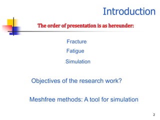
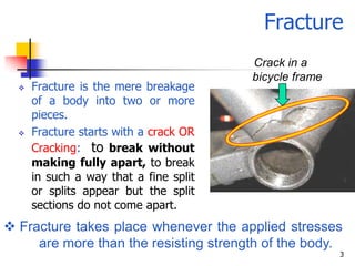
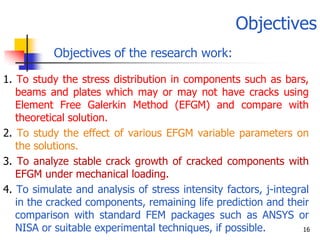
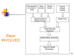
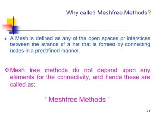
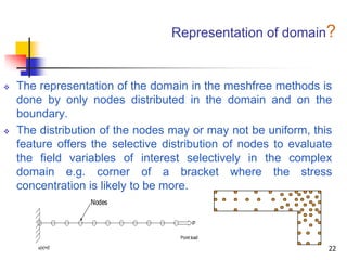
Synopsis
                       Presentation
                           on


“FRACTURE-FATIGUE SIMULATION USING MESHFREE METHODS”


         You are requested to please give your valuable
  Criticism/suggestions/ comments. You may use the contents
         but please send me a copy of your presentation.


                          Prepared

                 By Jeetender Singh Kushawaha
                             E-Mail:
                    k.Jitendrasingh@yahoo.com
                          09450935651
                                                         1
                              India
Introduction

             Fracture
             Fatigue
            Simulation


Objectives of the research work?


Meshfree methods: A tool for simulation

                                          2
Fracture
                                        Crack in a
                                        bicycle frame
     Fracture is the mere breakage
      of a body into two or more
      pieces.
     Fracture starts with a crack OR
      Cracking: to break without
      making fully apart, to break
      in such a way that a fine split
      or splits appear but the split
      sections do not come apart.
 Fracture takes place whenever the applied stresses
     are more than the resisting strength of the body.
                                                        3
Fracture            (Cont’d)

Three Modes of Cracking

                  Cracking

     Mode I     Opening mode

     Mode II    In-plane shearing/sliding mode


     Mode III   Out-of-plane shearing/tearing mode


         We shall mostly deal with
        Mode I in this research work
                                                 4
Fracture           (Cont’d)


             Types of Fracture


                                    Fatigue
Ductile     Brittle     Creep
                                    fracture


     Ductile fracture       Brittle fracture


                                               5
Fatigue
           Fatigue Characteristics
 Fatigue: Behavior & failure of material observed under
      fluctuating/ cyclic loads.
 Fatigue occurs at stresses that are considerably smaller
      than yield/ tensile stress of the material.
 These failures are dangerous because they occur without
     any warning. Typical machine components subjected
     to fatigue are automobile crank-shaft, bridges, aircraft
     landing gear, etc.
 Fatigue failures occur in both metallic and non-metallic
      materials, and are responsible for a large number/
      fraction of identifiable service failures of metals. 6
Fatigue        (Cont’d)

        Fatigue Identification 1
Fatigue fracture surface is perpendicular to the direction
      of an applied stress.


Any point with stress concentration such as sharp
     corner       or notch or metallurgical inclusion
     can act as point of initiation of fatigue crack


                                                              7
Fatigue          (Cont’d)

               Fatigue Identification 2
Fatigue failure can be recognized from the appearance of the fracture surface


     Granular
  rough surface
   before final
  brittle fracture
                                                                            8
Fatigue      (Cont’d)

       Fatigue Conditions/ Requisites


   Three basic requisites for occurrence of
    fatigue failure are:
      (a) a maximum tensile stress of sufficiently

       high value
      (b) a large enough variation or fluctuation in

       the applied stress, and
      (c) a sufficiently large number of cycles of

       applied stress.
                                                        9
Simulation
                    What is Simulation?

   Simulation is the process of designing a
    model of a real system and conducting
    experiments with this model for the purpose
    of either understanding the behavior of the
    system and/or evaluating various strategies/
    methodologies for the operation of the
    system.


                                                   10
Simulation        (Cont’d)


         Simulation allows us to:
   Model complex systems in a detailed way.
   Describe the behavior of systems.
   Construct theories or hypotheses that account
    for the observed behavior.
   Use the model to predict future behavior, that
    is, the effects that will be produced by
    changes in the system.
   Analyze, test and evaluate the proposed
    methods/ hypothesis/ systems.                11
Simulation   (Cont’d)


          Why use simulation?

   Test without building
        Experimental system.
        New concepts.
   Test without disturbing
        Costly experimentation.
        Unsafe experimentation.
   Test without destroying
        Determine limits of stress.
        Predict the residual life
                                              12
Simulation   (Cont’d)

 Simulation’s greatest strength
    is its ability to answer
  “what if” questions ...
What if a part is operated with a
           crack?


                                           13
Simulation   (Cont’d)

     Is simulation flawless?


 NO, Simulation has
its own drawbacks...


                                       14
Simulation   (Cont’d)

     Limitations of Simulation


   Some simulations may take longer period
    of time to develop.
   Different simulations produce different
    results in repeated run.
   Do not generate optimal solutions.
   Users have to provide all constraints and
    frequent intervention.
                                                    15
Objectives
           Objectives of the research work:

1. To study the stress distribution in components such as bars,
   beams and plates which may or may not have cracks using
   Element Free Galerkin Method (EFGM) and compare with
   theoretical solution.
2. To study the effect of various EFGM variable parameters on
   the solutions.
3. To analyze stable crack growth of cracked components with
   EFGM under mechanical loading.
4. To simulate and analysis of stress intensity factors, j-integral
   in the cracked components, remaining life prediction and their
   comparison with standard FEM packages such as ANSYS or
   NISA or suitable experimental techniques, if possible.        16
Literature Review 1
   The meshfree methods have been successfully
    applied in analysis and study of many fields with
    some limitations, such as:

   Crack propagation
   Large deformation
   Fracture mechanics
   Astronomy
   Simulation of explosion
                                                        17
Literature Review 2
   Electrostatics
   Collision and accident Simulation
   Animation
   Bio-mechanics
   Manufacturing processes involving
    large deformation, forging, rolling


                                          18
Meshfree Methods


    The objectives of the research work will
    be achieved by application of Meshfree
    methods as a simulation tool.

   Here onwards we shall have little introduction to
    meshfree methods:

   Steps involved in meshfree analysis?
   Why called meshfree?
   Discretization/ Representation of domain?
   Meshfree terminology?
                                                        19
Representation    Basis         Weight        Material
            by number of    function      function       property
               nodes                                     Loading


                     Approximation &                    Weak Form
                     Shape Function


                                       Nodal Discrete
                                         Equations


  Steps                       Global Matrix Assembly
INVOLVED
                                   Solve for Nodal
                                    Parameters

                                                                    20
Why called Meshfree Methods?


   A Mesh is defined as any of the open spaces or interstices
    between the strands of a net that is formed by connecting
    nodes in a predefined manner.


Mesh free methods do not depend upon any
 elements for the connectivity, and hence these are
 called as:

                  “ Meshfree Methods ”
                                                            21
Representation of domain?


   The representation of the domain in the meshfree methods is
    done by only nodes distributed in the domain and on the
    boundary.
   The distribution of the nodes may or may not be uniform, this
    feature offers the selective distribution of nodes to evaluate
    the field variables of interest selectively in the complex
    domain e.g. corner of a bracket where the stress
    concentration is likely to be more.
                  Nodes

                                          P

                                    Point load

        u(x)=0                                                   22
Meshfree terminology-1

Support domain and influence domain

   Support domain is defined as the field / area or
    domain that a point exerts an influence upon,
    whereas,
   Support influence is defined as the field / area or
    domain that a node exerts an influence upon.

                DOMAIN


                 NODE

                SUB-
                DOMAIN                               23
Meshfree terminology 2


   Node connectivity

       The connectivity of the nodes in meshfree methods is
        established by the over lapping domains of influence.


                                                                24
Suggestions


   Your questions, please!

   Your suggestions, please!


                                          25
26

Fracture fatigue simulation using meshfree methods

  • 1.
    Synopsis Presentation on “FRACTURE-FATIGUE SIMULATION USING MESHFREE METHODS” You are requested to please give your valuable Criticism/suggestions/ comments. You may use the contents but please send me a copy of your presentation. Prepared By Jeetender Singh Kushawaha E-Mail: k.Jitendrasingh@yahoo.com 09450935651 1 India
  • 2.
    Introduction Fracture Fatigue Simulation Objectives of the research work? Meshfree methods: A tool for simulation 2
  • 3.
    Fracture Crack in a bicycle frame  Fracture is the mere breakage of a body into two or more pieces.  Fracture starts with a crack OR Cracking: to break without making fully apart, to break in such a way that a fine split or splits appear but the split sections do not come apart.  Fracture takes place whenever the applied stresses are more than the resisting strength of the body. 3
  • 4.
    Fracture (Cont’d) Three Modes of Cracking Cracking Mode I Opening mode Mode II In-plane shearing/sliding mode Mode III Out-of-plane shearing/tearing mode We shall mostly deal with Mode I in this research work 4
  • 5.
    Fracture (Cont’d) Types of Fracture Fatigue Ductile Brittle Creep fracture Ductile fracture Brittle fracture 5
  • 6.
    Fatigue Fatigue Characteristics  Fatigue: Behavior & failure of material observed under fluctuating/ cyclic loads.  Fatigue occurs at stresses that are considerably smaller than yield/ tensile stress of the material.  These failures are dangerous because they occur without any warning. Typical machine components subjected to fatigue are automobile crank-shaft, bridges, aircraft landing gear, etc.  Fatigue failures occur in both metallic and non-metallic materials, and are responsible for a large number/ fraction of identifiable service failures of metals. 6
  • 7.
    Fatigue (Cont’d) Fatigue Identification 1 Fatigue fracture surface is perpendicular to the direction of an applied stress. Any point with stress concentration such as sharp corner or notch or metallurgical inclusion can act as point of initiation of fatigue crack 7
  • 8.
    Fatigue (Cont’d) Fatigue Identification 2 Fatigue failure can be recognized from the appearance of the fracture surface Granular rough surface before final brittle fracture 8
  • 9.
    Fatigue (Cont’d) Fatigue Conditions/ Requisites  Three basic requisites for occurrence of fatigue failure are:  (a) a maximum tensile stress of sufficiently high value  (b) a large enough variation or fluctuation in the applied stress, and  (c) a sufficiently large number of cycles of applied stress. 9
  • 10.
    Simulation What is Simulation?  Simulation is the process of designing a model of a real system and conducting experiments with this model for the purpose of either understanding the behavior of the system and/or evaluating various strategies/ methodologies for the operation of the system. 10
  • 11.
    Simulation (Cont’d) Simulation allows us to:  Model complex systems in a detailed way.  Describe the behavior of systems.  Construct theories or hypotheses that account for the observed behavior.  Use the model to predict future behavior, that is, the effects that will be produced by changes in the system.  Analyze, test and evaluate the proposed methods/ hypothesis/ systems. 11
  • 12.
    Simulation (Cont’d) Why use simulation?  Test without building  Experimental system.  New concepts.  Test without disturbing  Costly experimentation.  Unsafe experimentation.  Test without destroying  Determine limits of stress.  Predict the residual life 12
  • 13.
    Simulation (Cont’d) Simulation’s greatest strength is its ability to answer “what if” questions ... What if a part is operated with a crack? 13
  • 14.
    Simulation (Cont’d) Is simulation flawless? NO, Simulation has its own drawbacks... 14
  • 15.
    Simulation (Cont’d) Limitations of Simulation  Some simulations may take longer period of time to develop.  Different simulations produce different results in repeated run.  Do not generate optimal solutions.  Users have to provide all constraints and frequent intervention. 15
  • 16.
    Objectives Objectives of the research work: 1. To study the stress distribution in components such as bars, beams and plates which may or may not have cracks using Element Free Galerkin Method (EFGM) and compare with theoretical solution. 2. To study the effect of various EFGM variable parameters on the solutions. 3. To analyze stable crack growth of cracked components with EFGM under mechanical loading. 4. To simulate and analysis of stress intensity factors, j-integral in the cracked components, remaining life prediction and their comparison with standard FEM packages such as ANSYS or NISA or suitable experimental techniques, if possible. 16
  • 17.
    Literature Review 1  The meshfree methods have been successfully applied in analysis and study of many fields with some limitations, such as:  Crack propagation  Large deformation  Fracture mechanics  Astronomy  Simulation of explosion 17
  • 18.
    Literature Review 2  Electrostatics  Collision and accident Simulation  Animation  Bio-mechanics  Manufacturing processes involving large deformation, forging, rolling 18
  • 19.
    Meshfree Methods The objectives of the research work will be achieved by application of Meshfree methods as a simulation tool.  Here onwards we shall have little introduction to meshfree methods:  Steps involved in meshfree analysis?  Why called meshfree?  Discretization/ Representation of domain?  Meshfree terminology? 19
  • 20.
    Representation Basis Weight Material by number of function function property nodes Loading Approximation & Weak Form Shape Function Nodal Discrete Equations Steps Global Matrix Assembly INVOLVED Solve for Nodal Parameters 20
  • 21.
    Why called MeshfreeMethods?  A Mesh is defined as any of the open spaces or interstices between the strands of a net that is formed by connecting nodes in a predefined manner. Mesh free methods do not depend upon any elements for the connectivity, and hence these are called as: “ Meshfree Methods ” 21
  • 22.
    Representation of domain?  The representation of the domain in the meshfree methods is done by only nodes distributed in the domain and on the boundary.  The distribution of the nodes may or may not be uniform, this feature offers the selective distribution of nodes to evaluate the field variables of interest selectively in the complex domain e.g. corner of a bracket where the stress concentration is likely to be more. Nodes P Point load u(x)=0 22
  • 23.
    Meshfree terminology-1 Support domainand influence domain  Support domain is defined as the field / area or domain that a point exerts an influence upon, whereas,  Support influence is defined as the field / area or domain that a node exerts an influence upon. DOMAIN NODE SUB- DOMAIN 23
  • 24.
    Meshfree terminology 2  Node connectivity  The connectivity of the nodes in meshfree methods is established by the over lapping domains of influence. 24
  • 25.
    Suggestions  Your questions, please!  Your suggestions, please! 25
  • 26.

Editor's Notes

  • #11 Dictionary meaning “ to assume the mere appearance of , without the reality”
  • #13 Almost anything can be andalmost everything has been ...
  • #14 Simulation’s strength is its ability to answer “what if” questions so that the future can be improved considering the prevailing conditions ...
  • #15 Simulation has its own advantages and disadvantages