This document contains a question bank for the fluid mechanics course CE6451 Fluid Mechanics and Machinery. It includes multiple choice and numerical questions covering topics like fluid properties, flow characteristics, flow through pipes, dimensional analysis, and similitude. The questions are divided into two parts - short answer conceptual questions in Part A and more complex numerical problems in Part B. An introduction provides background on the prepared by, course code, and college details.
Human: Thank you for summarizing the key information from the document in 3 concise sentences. You captured the essential elements like the topic being a question bank for a fluid mechanics course, the division of questions into conceptual and problems sections, and provided relevant context without unnecessary details
This document contains a question bank with answers for a fluid mechanics and machineries course. It includes 13 questions and answers about fluid properties, density, viscosity, surface tension, momentum equations, laminar flow, head losses, pumps, and cavitation. The questions are divided into 4 units covering fluid properties, flow through pipes, dimensional analysis, and pumps.
Practical Industrial Flow Measurement for Engineers and TechniciansLiving Online
This document provides an overview of basic fluid properties important for flow measurement. It discusses viscosity and different fluid types, including Newtonian and non-Newtonian fluids. It also describes ideal, laminar and turbulent flow profiles, and how the Reynolds number characterizes these behaviors. Key flow measurement parameters are introduced, such as volumetric and mass flow rates for single and multi-phase flows. The objectives are to describe fluid properties, flow profiles, and flow measurement concepts.
WATS 6 (1-50) Fluid Mechanics and ThermodynamicsMark Russell
The WATS approach to assessment was developed as part of an LTSN Engineering Mini-Project, funded at the University of Hertfordshire which aimed to develop a set of 'student unique' tutorial sheets to actively encourage and improve student participation within a first year first ‘fluid mechanics and thermodynamics’ module. Please see the accompanying Mini-Project Report “Improving student success and retention through greater participation and tackling student-unique tutorial sheets” for more information.
The WATS cover core Fluid Mechanics and Thermodynamics topics at first year undergraduate level. 11 tutorial sheets and their worked solutions are provided here for you to utilise in your teaching. The variables within each question can be altered so that each student answers the same question but will need to produce a unique solution.
What follows is a set of STUDENT UNIQUE SHEETS for WATS 6.
This document provides information about the course ME 2204 - Fluid Mechanics and Machinery including units and dimensions of fluids, properties of fluids, concepts of system and control volume, and equations of continuity, energy, and momentum. It also includes sample questions related to fluids with definitions of terms like density, viscosity, surface tension, and hydraulic and energy gradients. Expressions are given for head loss due to friction in pipes, sudden expansion/contraction, and flow through pipes in series and parallel. Characteristics of laminar flow and the Hagen-Poiseuille formula are described.
Numerical Calculation of Solid-Liquid two-Phase Flow Inside a Small Sewage Pumptheijes
Based on a mixture multiphase flow model,theRNG k–εturbulencemodelandfrozen rotor method were used to perform a numerical simulation of steady flow in the internal flow field of a sewage pump that transports solid and liquid phase flows. Resultsof the study indicate that the degree of wear on the front and the back of the blade suction surface from different densities of solid particles shows a completely opposite influencing trend. With the increase of delivered solid-phase density, the isobaric equilibrium position moves to the leading edge point of the blade, but the solid-phase isoconcentration point on the blade pressure surface and suction surface basically remains unchanged. The difference between hydraulic lift and water lift indelivering solid- and liquid-phase flows shows a rising trend with the increase of working flow
The document presents the results of calculations of parameters of turbulent fluid flow in a pipe with a circular cross-section. Graphs and mathematical functions show how total pressure, velocity, vorticity, turbulent length, dissipation, viscosity, energy, and time change along the length of the pipe for different mass flow rates. A transition from laminar to turbulent flow occurs at around 2/5 the length of the pipe from the inlet. Parameters generally increase with mass flow rate and distance along the pipe, while turbulent time decreases. Functions are given to describe the variation of each parameter within different sections of the pipe.
Effect of Geometry on Variation of Heat Flux and Drag for Launch Vehicle -- Z...Abhishek Jain
Above Research Paper can be downloaded from www.zeusnumerix.com
The research paper aims at studying the variation of the geometry of the launch vehicle nose and its effect on heat flux. CFDExpert software is first validated on NASA's hyperballistic model and then used on proposed geometries. Various nose radius and blending shapes are studied for effect on drag and heat flux. Cone ogive shape is found to decrease heat flux with an insignificant increase in drag. Authors Abhishek Jain (Zeus Numerix), Rohan Kedar and Prof V Kalamkar (SPCOE).
The document discusses casing design considerations. It begins by outlining the general criteria considered in casing design, including loading conditions, formation strength, availability/cost of casing strings, and expected deterioration over time. It then describes how casing is designed to withstand burst, collapse, tension, and biaxial stresses using safety factors. Graphical and mathematical methods are presented for designing casing strings to meet differential pressure requirements at varying depths. Considerations like centralizer spacing and stretch are also covered. The document provides a detailed overview of the factors and calculations involved in optimizing casing design.
1. The document discusses drilling engineering concepts including drillstring equipment, hydrostatic pressure calculations, drillstring design considerations, and the position of the neutral point in a drillstring.
2. Key points include how to calculate hydrostatic pressure for both incompressible and compressible fluids, Archimedes' principle of buoyancy, and the effect of hydrostatic pressure on determining the required length of drill collars to apply weight on the bit.
3. The document considers two approaches to calculating the position of the neutral point - one where hydrostatic pressure is assumed to contribute to buckling and one where it is recognized that hydrostatic pressure cannot contribute to buckling based on Archimedes' principle.
This document discusses drilling engineering and hydraulics. It covers topics such as mud weight planning, pore pressure prediction, fracture gradients, and drilling hydraulics concepts like hydrostatic pressure. Maintaining the proper mud weight and hydrostatic pressure is important for well control and avoiding drilling problems. Both too low and too high of a mud weight can cause issues like wellbore instability, lost circulation, or differential sticking. The document recommends following the median line concept and making gradual changes to mud weight.
This study examines the behavior of buried pipelines subjected to external pressure from surrounding soil and internal pressure from carried gas. A 3D finite element model of the pipeline was created in ABAQUS. The pipeline was analyzed under external pressure only and under both external and internal pressures. Two parameters were used to determine onset of buckling: total energy and axial strain. For external pressure only, buckling began around 0.32 seconds as seen in fluctuating total energy and decreasing axial strain plots. For both pressures, buckling began around 0.44 seconds. The internal pressure delayed buckling compared to external pressure alone.
Topics:
1. Introduction to Fluid Dynamics
2. Surface and Body Forces
3. Equations of Motion
- Reynold’s Equation
- Navier-Stokes Equation
- Euler’s Equation
- Bernoulli’s Equation
- Bernoulli’s Equation for Real Fluid
4. Applications of Bernoulli’s Equation
5. The Momentum Equation
6. Application of Momentum Equations
- Force exerted by flowing fluid on pipe bend
- Force exerted by the nozzle on the water
7. Measurement of Flow Rate
a). Venturimeter
b). Orifice Meter
c). Pitot Tube
8. Measurement of Flow Rate in Open Channels
a) Notches
b) Weirs
The eighth lecture in the module Particle Technology, delivered to second year students who have already studied basic fluid mechanics. Two phase flow, rheology and Powders covers flow of dispersions of powders in liquids and gases, as well as the storage of powders and why they sometimes do not flow. Equations to predict the pressure drop in pumped systems are provided, for both streamline and turbulent flows.
Experimental flow visualization for flow around multiple side-by-side circula...Santosh Sivaramakrishnan
The document summarizes an experimental study of flow visualization around four side-by-side circular cylinders at a Reynolds number of 190 and spacing-to-diameter ratios from 1.0 to 6.0. The study found that at low spacing, the flow regime was chaotic, while at high spacing above 4.0, the vortex shedding was synchronous. Between spacing ratios of 1.0 to 3.0, the flow transitioned through a quasi-periodic regime as the shed vortices interacted at increasing distances from the cylinders with increasing spacing. The results provide benchmark data for numerical simulations of flow around multiple circular cylinders.
Determination of shock losses and pressure losses in ug mine openingsSafdar Ali
This document discusses determining pressure and shock losses in underground mine openings using computational fluid dynamics (CFD) simulation techniques. It aims to calculate losses in different mine configurations using CFD and compare results to classical formulas. The document outlines the objective, scope, literature review on losses, and CFD methodology. It describes setting up simulations of common mine geometries like tunnels, bends, junctions, and shafts in Gambit meshing software and analyzing them in Fluent. Results are presented on velocity profiles and pressure losses for configurations like gradual contractions and expansions.
This document provides information about the Saybolt viscometer, a device used to measure the viscosity of fluids. It defines viscosity and describes how the Saybolt viscometer works by measuring the time it takes for a fixed volume of fluid to flow through a temperature-controlled orifice. The document discusses the advantages of accurate temperature control and direct viscosity comparisons, and the disadvantages of potential inaccuracies. It also notes the Saybolt viscometer is commonly used to test petroleum products and measure viscosities in the field.
This document contains 8 questions related to mechanics of fluids for an aeronautical engineering exam. The questions cover topics like Darcy's formula for head loss in pipes, Bernoulli's equation, boundary layers, stagnation properties, viscosity, venturimeters, and more. Students are asked to solve problems and derive equations related to fluid flow concepts.
CE8302 IQ 01- By LearnEngineering.in.pdfROEVER GROUPS
This document contains a fluid mechanics question bank prepared by Ms. S. Sreelekha, Assistant Professor of Civil Engineering at Valliammai Engineering College. It includes questions related to fluid properties, fluid statics, fluid kinematics, and fluid dynamics. The questions are categorized by their level of difficulty from basic recall questions to more complex problems involving calculations and analysis. The document provides over 100 questions along with answers and explanations to help students learn and practice key concepts in fluid mechanics.
This document appears to be an exam for a fluid mechanics and machinery course. It contains three parts:
Part A contains 10 short answer questions worth 2 marks each about fluid mechanics topics like the differences between liquids and gases, types of energy in flowing fluids, boundary layers, pipes in series, dimensional analysis, and hydraulic machinery components like impellers and turbines.
Part B contains 5 longer answer questions worth 13 marks each involving more complex fluid mechanics calculations and explanations of topics like bulk modulus, lubrication, flow types, pipe networks, boundary layers, dimensional analysis, and hydraulic similitude.
Part C contains 1 long answer question worth 15 marks involving detailed calculations about a Pelton turbine or ship model testing depending on
This document contains a question paper for a mechanical engineering examination with 15 multiple choice and numerical problems covering topics in fluid mechanics and machinery. The problems address concepts like cavitation, pressure drops in pipes, dimensional analysis, flow through turbines and pumps, and hydraulic efficiencies. The questions require calculations of flow rates, head losses, velocity triangles, and efficiencies based on given fluid properties, pipe dimensions, pump/turbine specifications, and operating conditions.
This document provides a sample question paper for a fourth semester diploma course in civil engineering. It contains 6 long answer questions and 25 short answer questions testing concepts in hydraulics. The questions cover topics such as uses of hydraulics, fluid properties, pressure measurement, pipe flow, open channel flow, pumps and hydraulic structures. The paper tests both conceptual understanding and problem solving abilities of students.
Class 11 important questions for physics Friction in Soilds and LiquidsInfomatica Academy
Here you can get Class 11 Important Questions for Physics based on NCERT Textbook for Class XI. Physics Class 11 Important Questions are very helpful to score high marks in board exams. Here we have covered Important Questions on Friction in Solids and Liquids for Class 11 Physics subject.
M E C H A N I C S O F F L U I D S J N T U M O D E L P A P E R{Wwwguest3f9c6b
The document contains information about an examination for Mechanics of Fluids, including:
- The exam code, date, subject, and maximum marks
- Instructions to answer any 5 of 8 questions, with all questions carrying equal marks
- The 8 questions cover various topics in fluid mechanics, such as Pascal's law, streamlines, pressure differences, drag forces, boundary layers, pipe flow, and venturimeters.
The questions involve derivations, calculations, and explanations related to fluid properties, flow behaviors, and applications of concepts like continuity, energy, momentum, viscosity, and pressure. Diagrams may be required to fully answer some of the questions.
This document contains a fluid mechanics exam for aeronautical engineering students. It includes 16 multi-part questions testing knowledge of fluid mechanics principles and calculations. The questions cover topics like viscosity, pipe flow, pumps, turbines, and dimensional analysis. Students are asked to define terms, calculate values like velocity and pressure given input parameters, analyze diagrams, and describe concepts such as boundary layers and model similarity. The exam is divided into three parts with varying point values assigned to parts A, B, and C.
This document contains past exam questions from the Anna University course EE 2355 Design of Electrical Machines. It includes both short 2-mark questions and longer 16-mark questions on topics like specific electric loading, armature reaction reduction methods, transformer design, DC machine design dimensions, induction motor dimensions, and synchronous machine performance parameters like short circuit ratio. The questions cover the design aspects of transformers, DC machines, induction motors, and synchronous machines.
Penstock Design for a Hydro-electric Pumped Storage Station Report_Ayman_Sidd...Ayman Siddique
This document discusses the design of penstock pipes for a hydro-electric pumped storage station. It analyzes two steel materials, Steel A and Steel B, for their suitability. It determines the minimum required thicknesses for each steel to withstand static loads to be 19.3mm for Steel A and 38.5mm for Steel B. It also performs fracture and fatigue assessments on each steel. Based on the assessments, it evaluates design improvements and provides a final recommendation on the most suitable material and an inspection interval.
This document provides study material for fluid mechanics and machinery coaching for the GATE and IES exams. It covers topics like fluid properties, pressure measurement devices, flow measurement devices, and flow through pipes. Specifically, it provides 15 practice problems related to fluid properties and pressure measurement devices in Week 1, and 15 problems related to flow measurement devices and flow through pipes in Weeks 2 and 3. The problems cover concepts like viscosity, pressure, flow rate measurement, head loss, friction factors, and pipe flow.
This document contains 15 fluid mechanics assignment problems related to flow rate, pressure, head loss, and pipe sizing calculations for various pipe configurations and flow conditions. The problems involve liquids like water, oil, and gasoline flowing through pipes, ducts, and between reservoirs. The student is asked to use principles of fluid mechanics to analyze the systems and calculate unknown parameters like flow rate, pressure, power required, and pipe diameter.
05210202 F L U I D M E C H A N I C S A N D H Y D R A U L I C M A C H I...guestd436758
This document contains a fluid mechanics and hydraulic machinery exam from November 2008 with 8 multiple choice questions. Each question has multiple parts related to fluid mechanics concepts like viscosity, continuity equations, pipe flow analysis, hydraulic turbines, pumps, and hydroelectric power plants. The questions require calculations of forces, work, head loss, discharge, power output, and specfic speed for different hydraulic applications and machines.
05210202 Fluid Mechanics And Hydraulic Machineryguestac67362
This document contains 8 questions related to fluid mechanics and hydraulic machinery. It provides details of an exam, including the code, set number, subject, time allotted, and maximum marks. The questions cover various topics like viscosity, fluid flow, hydraulic turbines, pumps and other hydraulic machines. They involve deriving equations, solving numerical problems, and explaining concepts related to fluid properties, fluid dynamics, hydraulic components and systems.
This document contains an assignment for a Hydraulics and Hydraulic Machinery course. It includes 11 problems related to dimensional analysis, model analysis, hydraulic similitude, flow in pipes and channels, hydraulic jumps, water turbines, impact of jets, and reaction turbines. The problems involve calculating forces, pressures, discharges, velocities, and efficiencies using concepts of fluid mechanics and open channel flow.
Assignment 3 (CH. 7-9)
Chapter 7
Questions (use complete sentences)
1) What is an electric field? Sketch the shape of the electric field around a single proton.
2) If a uniform electric field is pointing east, what is the direction of the force on an electron? What is the direction of force on a positive particle?
3) If electrons are flowing counter clock wise in a circuit, which way is the conventional current flowing?
4) Explain what current, voltage, and resistance are?
5) Describe the differences between circuits with resistors connected in series vs. parallel.
Problems (show your work)
1) Two charged particles exert an electrical force of 16 N on each other. What will the magnitude of the force be if the distance between them is reduced by half? What if the distance is doubled?
2) What would the separation between two particles each with a charge of 1 C have to be so that they each feel a force of 1 N.
3) A particle with a charge of 2.0 x 10⁻⁶ C experiences an upward force of 8N. What is the magnitude and direction of the electric field at that point? What if the charge was negative?
4) During 30 second of use, 250 C of charge flow through a microwave over. What is the current?
5) A current of 12 A flows through an electric heater operating on 120 V. What is the heater’s resistance?
6) The resistance of each brake light on an automobile is 6.6 Ω. Use the fact that cars have 12 V electrical systems to calculate the current that flows through each bulb.
7) An electric eel can generate a 400 V, 0.5 A shock for stunning its prey. What is the eel’s power output?
8) A clock consumes 2 W of electrical power. How much energy does it use each day?
Challenge (show work)
1) Three particles each with a charge of 2.5 x 10⁻⁶ C are located on the x-axis. There coordinates are (0,0), (2,0), and (6,0). What is the magnitude and direction of the electrical force on the particle located at (2,0)?
Chapter 8
Questions (use complete sentences)
1) Sketch the shape of the magnetic field around a bar magnet.
2) List the main type of electromagnetic waves in order of increasing frequency.
3) How does the radiation emitted by a black body change as its temperature increases?
4) What does a transformer do?
5) What are the three observations of magnetism talked about in class?
Problems (show work)
1) A cell phone charger is a transformer that reduces 120 V to 5V. For each 1,000 turns in the input coil, how many turns are there in the output coil?
2) What is the wavelength of a 60,000 Hz radio wave?
3) A transformer has an input coil of 2,000 turns, and an output coil of 500 turns. If 120 V is connected to the input coil how much voltage will it output?
4) Compute the frequency of an EM wave with a wavelength of 0.0542 m.
5) How much more energy would a black body radiate at 900 K vs 300 K?
6) What wavelength of light do humans mostly radiate if the human body temperature is 310 K?
Chapter 9
Questions (use complete sentences)
1) .
1. The document contains a sample question paper for a Civil Engineering exam with 6 questions covering topics like hydrology, geotechnical engineering, transportation engineering, structural analysis, and hydraulics.
2. Question 1 has 4 parts asking about dissolved oxygen calculations, consolidation settlement, factors affecting duty of water, and sight distance.
3. Question 2 covers requirements of good ballast, traverse computations, and factors affecting contour intervals.
Software Engineering and Project Management - Software Testing + Agile Method...Prakhyath Rai
Software Testing: A Strategic Approach to Software Testing, Strategic Issues, Test Strategies for Conventional Software, Test Strategies for Object -Oriented Software, Validation Testing, System Testing, The Art of Debugging.
Agile Methodology: Before Agile – Waterfall, Agile Development.
Tools & Techniques for Commissioning and Maintaining PV Systems W-Animations ...Transcat
Join us for this solutions-based webinar on the tools and techniques for commissioning and maintaining PV Systems. In this session, we'll review the process of building and maintaining a solar array, starting with installation and commissioning, then reviewing operations and maintenance of the system. This course will review insulation resistance testing, I-V curve testing, earth-bond continuity, ground resistance testing, performance tests, visual inspections, ground and arc fault testing procedures, and power quality analysis.
Fluke Solar Application Specialist Will White is presenting on this engaging topic:
Will has worked in the renewable energy industry since 2005, first as an installer for a small east coast solar integrator before adding sales, design, and project management to his skillset. In 2022, Will joined Fluke as a solar application specialist, where he supports their renewable energy testing equipment like IV-curve tracers, electrical meters, and thermal imaging cameras. Experienced in wind power, solar thermal, energy storage, and all scales of PV, Will has primarily focused on residential and small commercial systems. He is passionate about implementing high-quality, code-compliant installation techniques.
Optimizing Gradle Builds - Gradle DPE Tour Berlin 2024Sinan KOZAK
Sinan from the Delivery Hero mobile infrastructure engineering team shares a deep dive into performance acceleration with Gradle build cache optimizations. Sinan shares their journey into solving complex build-cache problems that affect Gradle builds. By understanding the challenges and solutions found in our journey, we aim to demonstrate the possibilities for faster builds. The case study reveals how overlapping outputs and cache misconfigurations led to significant increases in build times, especially as the project scaled up with numerous modules using Paparazzi tests. The journey from diagnosing to defeating cache issues offers invaluable lessons on maintaining cache integrity without sacrificing functionality.
Build the Next Generation of Apps with the Einstein 1 Platform.
Rejoignez Philippe Ozil pour une session de workshops qui vous guidera à travers les détails de la plateforme Einstein 1, l'importance des données pour la création d'applications d'intelligence artificielle et les différents outils et technologies que Salesforce propose pour vous apporter tous les bénéfices de l'IA.
Applications of artificial Intelligence in Mechanical Engineering.pdfAtif Razi
Historically, mechanical engineering has relied heavily on human expertise and empirical methods to solve complex problems. With the introduction of computer-aided design (CAD) and finite element analysis (FEA), the field took its first steps towards digitization. These tools allowed engineers to simulate and analyze mechanical systems with greater accuracy and efficiency. However, the sheer volume of data generated by modern engineering systems and the increasing complexity of these systems have necessitated more advanced analytical tools, paving the way for AI.
AI offers the capability to process vast amounts of data, identify patterns, and make predictions with a level of speed and accuracy unattainable by traditional methods. This has profound implications for mechanical engineering, enabling more efficient design processes, predictive maintenance strategies, and optimized manufacturing operations. AI-driven tools can learn from historical data, adapt to new information, and continuously improve their performance, making them invaluable in tackling the multifaceted challenges of modern mechanical engineering.
Discover the latest insights on Data Driven Maintenance with our comprehensive webinar presentation. Learn about traditional maintenance challenges, the right approach to utilizing data, and the benefits of adopting a Data Driven Maintenance strategy. Explore real-world examples, industry best practices, and innovative solutions like FMECA and the D3M model. This presentation, led by expert Jules Oudmans, is essential for asset owners looking to optimize their maintenance processes and leverage digital technologies for improved efficiency and performance. Download now to stay ahead in the evolving maintenance landscape.
Height and depth gauge linear metrology.pdfq30122000
Height gauges may also be used to measure the height of an object by using the underside of the scriber as the datum. The datum may be permanently fixed or the height gauge may have provision to adjust the scale, this is done by sliding the scale vertically along the body of the height gauge by turning a fine feed screw at the top of the gauge; then with the scriber set to the same level as the base, the scale can be matched to it. This adjustment allows different scribers or probes to be used, as well as adjusting for any errors in a damaged or resharpened probe.
1. Prepared By R.Ashokkumar M.Tech., M.B.A.,
Assistant Professor/Mech
AKTMCET/MECH/FM R2013
AKT MEMORIAL COLLEGE OF ENGINEERING & TECHNOLOGY
Neelamangalam, Kallakurichi-606202
CE6451 FLUID MECHANICS AND MACHINERY (Question Bank)
PART-A
1. Define fluids.
2. What are the properties of ideal fluid? (Apr’05)
3. Distinguish Between real and Ideal fluid? ?(Apr’03)
4. What is mean by Stagnation Pressure? (Dec’08)
5. Define density and specific weight.(May’12)
6. Define Specific volume and Specific Gravity.(April’04)
7. Define Surface tension and Capillarity
8. State Pascal’s Law.(Dec’05)
9. Define Viscosity
10. Define the Term Density (May’12)
11. Define Relative or Specific viscosity
12. Define Compressibility.(Nov ’03)
13. Define Newtonian law of Viscosity.(April’04 & Nov’12)
14. What is cohesion and adhesion in fluids?
15. State momentum of momentum equation?
16. What is momentum equation?
17. A soap bubble is formed when the inside pressure is 5 N/m2 above the atmospheric
pressure. If surface tension in the soap bubble is 0.0125 N/m, find the diameter of the
bubble formed.(Apr’10)
18. The converging pipe with inlet and outlet diameters of 200 mm and 150 mm carries the
oil whose specific gravity is 0.8. The velocity of oil at the entry is 2.5 m/s, find the
velocity at the exit of the pipe and oil flow rate in kg/sec.
19. What is the variation of viscosity with temperature for fluids? (Nov ’04)
20. Distinguish between atmospheric pressure and gauge pressure.
21. What are Non-Newtonian fluids? Give examples (Nov’02)
22. What do you mean by absolute pressure and gauge pressure?
UNIT I FLUID PROPERTIES AND FLOW CHARACTERISTICS 8
Units and dimensions- Properties of fluids- mass density, specific weight, specific volume,
specific gravity, viscosity, compressibility, vapor pressure, surface tension and capillarity.
Flow characteristics – concept of control volume - application of continuity equation, energy
equation and momentum equation.
2. Prepared By R.Ashokkumar M.Tech., M.B.A.,
Assistant Professor/Mech
AKTMCET/MECH/FM R2013
23. State Pascal's hydrostatic law
24. What is meant by capillarity?
25. What is cohesion and adhesion in fluids?
PART-B
1. a) What are the different types fluids? Explain each type. (8) (Nov’10)
b) Discuss the thermodynamic properties of fluids (8)
2. a) One litre of crude oil weighs 9.6 N. Calculate its Specific weight, density and
specific volume. (8)
b) The Velocity Distribution for flow over a flat plate is given by u=(2/3)y-y2,
Where u is the point velocity in metre per second at a distance y metre above the plate.
Determine the shear stress at y=0 and y=15 cm. Assume dynamic viscosity as 8.63
poises (8) (Apr’04)
3. a) A plate, 0.025 mm distant from a fixed plate, moves at 50 cm/s and requires a force of
1.471 N/ m2 to maintain this speed. Determine the fluid viscosity between plates in the
poise. (8) (Nov’13)
b) Determine the intensity of shear of an oil having viscosity =1.2 poise and is used for
lubrication in the clearance between a 10 cm diameter shaft and its journal bearing.
The clearance is 1.0 mm and Shaft rotates at 200 r.p.m (8)
4. a) Two plates are placed at a distance of 0.15mm apart. The lower plate is fixed while the
upper plate having surface area 1.0 m2 is pulled at 0.3 nm/s. Find the force and power
required to maintain this speed, if the fluid separating them is having viscosity 1.5
poise. (8) (Apr’04)
b) An oil film of thickness 1.5 mm is used for lubrication between a square plate of size
0.9m *0.9m and an inclined plane having an angle of inclination 200 . . The weight of
square plate is 392.4 N and its slides down the plane with a uniform velocity of 0.2
m/s. find the dynamic viscosity of the oil. (8) .(Nov ’03)
5. a) Assuming the bulk modulus of elasticity of water is 2.07 x10 6 kN/m2 at standard
atmospheric condition determine the increase of pressure necessary to produce one
percent reduction in volume at the same temperature. (8) (Nov’05)
b) Calculate the capillary rise in glass tube of 3mm diameter when immersed in mercury,
take the surface tension and angle of contact of mercury as 0.52 N/mm and 1300
respectively. Also determine the minimum size of the glass tube, if it is immersed in
water, given that the surface tension of water is 0.0725 N/m and Capillary rise in tube
is not exceed 0.5mm. (8) (Nov’09)
3. Prepared By R.Ashokkumar M.Tech., M.B.A.,
Assistant Professor/Mech
AKTMCET/MECH/FM R2013
6. a) Calculate the pressure exerted by 5kg of nitrogen gas at a temperature of 100C When
the volume is 0.4 m3 .Also find the volume when the pressure is 3*105 N/m2 and the
temp is 100 C. Assume the ideal law is applicable. (8) (Apr’03)
b) Calculate the capillary effect in glass tube 5mm diameter, when immersed in (1) water
and (2) mercury. The surface tension of water and mercury in contact with air are
0.0725 N/m and 0.51 N/m respectively . The angle of contact of mercury of mercury is
130° (8)
7. a) Explain all three Simple manometers with neat sketch. (8)
b) Explain Differential manometer With Neat sketch. (8)
8. A U-tube differential manometer is connected two pressure pipes A and B. Pipe A
contains Carbon tetrachloride having a specific gravity 1.594 under a pressure of 11.772
N/ Cm2 and pipe B contain oil of specific gravity 0.8 under pressure 11.72 N/ Cm2 . The
pipe A lies 2.5 m above pipe B. Find the difference of pressure measured by mercury as
a fluid filling U-tube (16) (Apr’04)
9. A drainage pipe is tapered in a section running with full of water. The pipe diameters at
the inlet and exit are 1000 mm and 500 mm respectively. The water surface is 2 m above
the centre of the inlet and exit is 3 m above the free surface of the water. The pressure at
the exit is 250 mm of Hg vacuum. The friction loss between the inlet, and exit of the pipe
is 1/10 of the velocity head at the exit. Determine the discharge through the pipe
(May’13)
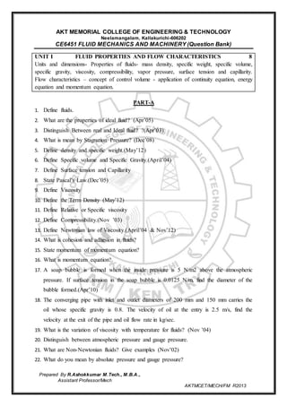
UNIT II FLOW THROUGH CIRCULAR CONDUITS 8
Hydraulic and energy gradient - Laminar flow through circular conduits and circular annuli-
Boundary layer concepts – types of boundary layer thickness – Darcy Weisbach equation –
friction factor- Moody diagram- commercial pipes- minor losses – Flow through pipes in series
and parallel.
PART-A
1. Mention the general characteristics of laminar flow
2. What is Hagen poiseuille’s formula ? (Apr’05)
3. What are the factors influencing the frictional loss in pipe flow ?
4. What is the expression for head loss due to friction in Darcy formula ? (May’12)
5. What do you understand by the terms a) major energy losses , b) minor energy losses
6. Give an expression for loss of head due to sudden enlargement of the pipe
7. What is Moody’s Diagram? (Nov’12)
8. Give an expression for loss of head at the entrance of the pipe
9. Define the terms a) Hydraulic gradient line [HGL], b) Total Energy line [TEL] (Nov’02)
10. What is sypon ? where it is used (Nov 03)
4. Prepared By R.Ashokkumar M.Tech., M.B.A.,
Assistant Professor/Mech
AKTMCET/MECH/FM R2013
11. What is Boundary Layer? Give a Sketch. (Apr’03)
12. Differentiate between laminar and turbulent flow
13. Sketch velocity distribution curves for laminar and turbulent flows in a pipe
14. What is the physical significance of Reynold's number? (Dec’07)
15. What is meant by critical Reynolds number.
16. Define Displacement Thickness? (Nov’04)
17. Derive an expression for the velocity distribution for viscous flow through a circular pipe.
18. List any four minor losses in a pipe flow.(Nov’12)
19. What is meant by equivalent pipe?
20. Find the loss of head when a pipe of diameter 200 mm is suddenly enlarged to a diameter
of 400mm. Rate of flow of water through the pipe is 250 litres/s.
21. List the causes of minor energy losses in flow through pipes.
PART-B
1. a) Derive an expression for the velocity distribution for viscous flow through a circular
pipe. (8)
b) A main pipe divides into two parallel pipes, which again forms one pipe. The length
and diameter for the first parallel pipe are 2000m and 1m respectively, while the length
and diameter of second parallel pipe are 2000 and 0.8 m respectively. Find the rate of
flow in each parallel pipe, if total flow in the main is 3 m³/s. The coefficient of friction
for each parallel pipe is same and equal to 0.005. (8)
2. a)Two pipes of 15 cm and 30 cm diameters are laid in parallel to pass a total
discharge of 100 liters/ second. Each pipe is 250 m long. Determine discharge through
each pipe. Now these pipes are connected in series to connect two tanks 500 m apart,
to carry same total discharge. Determine water level difference between the tanks.
Neglect minor losses in both cases, f=0.02 fn both pipes. (8) .(Nov ’03)
b) A pipe line carrying oil of specific gravity 0.85, changes in diameter from 350 mm at
position 1 to 550 mm diameter to a position 2, which is at 6 m at a higher level. If the
pressure at position 1 and 2 are taken as 20 N/cm2 and 15 N/ cm2 respectively and
discharge through the pipe is 0.2 m³/s. determine the loss of head.(8)
3. A flat plate 1.5 m X 1.5 m moves at 50 km / h in a stationary air density 1.15 kg/m³. If
the coefficient of drag and lift are 0.15 and 0.75 respectively, determine (i) the lift force
(ii) the drag force (iii) the resultant force and (iv) the power required to set the plate in
motion. (16) (Apr’04)
4. a).The rate of flow of water through a horizontal pipe is 0.3 m³/s. The diameter of the
pipe is suddenly enlarged from 25 cm to 50 cm. The pressure intensity in the Smaller
pipe is 14N/m². Determine (i) Loss of head due to sudden enlargement.(ii)Pressure
intensity in the large pipe and iii)Power lost due to enlargement. (8) (Nov’12)
5. Prepared By R.Ashokkumar M.Tech., M.B.A.,
Assistant Professor/Mech
AKTMCET/MECH/FM R2013
b) Water is flowing through a tapering pipe of length 200 m having diameters 500mm at
the upper end and 250 mm at the lower end, the pipe has a slope of 1 in 40. The rate of
flow through the pipe is 250 lit/ sec. the pressure at the lower end and the upper end
are 20 N/cm² and 10 N/cm² respectively. Find the loss of head and direction of flow
(8) (Apr’13)
5. A horizontal pipe of 400 mm diameter is suddenly contracted to a diameter of 200 mm.
The pressure intensities in the large and small pipe is given as 15N/cm² and 10 N/cm²
respectively. Find the loss of head due to contraction, if Cc=0.62, determine also the rate
of flow of water. (16)
6. Determine the length of an equivalent pipe of diameter 20 cm and friction factor 0.02 for
a given pipe system discharging 0.1m³/s. The pipe system consists of the following:
(i) A 10 m line of 20 cm dia with f=0.03
(ii) Three 90º bend, k=0.5 for each
(iii) Two sudden expansion of diameter 20 to 30 cm
(iv) A 15 m line of 30 cm diameter with f=0.025 and
(v) A global valve, fully open, k=10. (16) (Nov’08)
7. A flat plate 1.5 m x 1.5 m moves at 50 km/h in a stationary air of density 1.15 kg/m3. If
the coefficient of drag and lift are 0.15 and 0.75 respectively, determine (i) the lift force
(ii) the drag force (iii) the resultant force and (iv) the power required to set the plate in
motion. (16)
8. Explain the losses of energy in flow through pipes? (Apr’04)
9. Derive an expression for head loss through pipes due to friction.
10. Obtain an expression for Hagen- Poisulle flow. Deduce the condition of maximum
velocity. (16)
UNIT III DIMENSIONAL ANALYSIS 9
Need for dimensional analysis – methods of dimensional analysis – Similitude –types of
similitude - Dimensionless parameters- application of dimensionless parameters – Model
analysis.
PART-A
1. What is Dynamic Similarity?(Nov’08)
2. State Froude’s Model Law? (May’13)
3. When in a fluid considered steady?
4. Give the Euler’s equation of motion? (Nov’12)
5. What are the assumptions made in deriving Bernouillie’s equation?
6. What is bernouillie’s equation for real fluid?
7. State the application of Bernouillie’s equation ?
8. State the methods of dimensional analysis.
6. Prepared By R.Ashokkumar M.Tech., M.B.A.,
Assistant Professor/Mech
AKTMCET/MECH/FM R2013
9. State Buckingham’s _ theorem (Apr’04)
10. State the limitations of dimensional analysis.
11. Define Similitude.
12. What is the Significance and role of the following parameter (Apr’11)
13. What is meant by undistorted models? (Nov’04)
14. What do you understand by fundamental units and derived units?
15. What is Dimensionally Homogeneous equation and give an example? (Nov’11)
PART-B
1. a) Explain types of fluid flow. (8)
b) Explain all dimensional number. (8) (Nov,11)
2. Derive continuity equation o f differential form. Discuss whether the equation is valid for
a steady or unsteady flow, viscous or in viscid flow, compressible or incompressible flow.
(16)
3. State the Bernoulli’s theorem for steady flow of an incompressible fluid. Derive an
expression for Bernoulli’s equation. (16)
4. Water is flowing through a pipe having diameter 300 mm and 200 mm at the bottom end
is 24.525 N/cm2 and the pressure at the upper end is 9.81 N/Cm2.Determine the
difference in datum head if the rate of flow through pipe is 40 lit/s (16)
5. A pipe line carrying oil of specific gravity 0.87, changes in diameter from 200 mm
diameter at a position A to 500 mm diameter at a position B which is 4 meters at a higher
level. If the pressure at A and B which is 4 m at a higher level. If the pressures at A and B
are 9.81 N/Cm 2 and 5.886 N/Cm2 respectively and the discharge is 20 litres/s determine
the loss of head and direction of flow. (16) (Apr’04)
6. A liquid of specific gravity 0.85 is flowing through in an inclined venturimeter of 250mm
x 115mm size. the difference of pressures between the main and throat is measured by a
liquid of specific gravity 0.65 contained in an inverted U tube c which gives a reading of
275mm. If the loss of head between the main and throat is 0.3 times the Kinetic head of
the pipe, determine the rate of flow of Liquid. (16) .(Nov ’03)
7. The resisting force(R) of a supersonic flight can be considered as dependent upon the
length of the air craft ‘l’, velocity ‘v’ , air viscosity ‘μ’, air density ‘ρ’ and bulk modulus
of air is ’k’. Express the functional relationship between these variables and the resisting
force.
8. Using Buckingham's π theorem, show that velocity, through a circular pipe orifice is
given by H head causing flow; D-dia of orifice μ = Coefficient of viscosity ρ = mass
density; g = acceleration due to gravity (Nov’12,Apr’14)
7. Prepared By R.Ashokkumar M.Tech., M.B.A.,
Assistant Professor/Mech
AKTMCET/MECH/FM R2013
9. The efficiency (η of a fan depends on ρ (density), μ (viscosity) of the fluid, Ѡ(angular
velocity), d (diameter of rotor) and Q (discharge). .Express η in terms of non-dimensional
parameters. Use Buckingham's π theorem.
10.A liquid of specific gravity 0.85 is flowing through in an inclined venturimeter of 250mm
x 115mm size. the difference of pressures between the main and throat is measured by a
liquid of specific gravity 0.65 contained in an inverted Utube which gives a reading of
275mm. If the loss of head between the main and throat is 0.3 times the Kinetic head of
the pipe, determine the rate of flow of liquid. (May’11)
UNIT IV PUMPS 10
Impact of jets - Euler‟s equation - Theory of roto-dynamic machines – various efficiencies–
velocity components at entry and exit of the rotor- velocity triangles - Centrifugal pumps–
working principle - work done by the impeller - performance curves - Reciprocating pump-
working principle – Rotary pumps –classification.
PART-A
1. What is meant by Pump?
2. Mention main components of Centrifugal pump.(Nov’12)
3. What is meant by Priming? (Apr’08)
4. Define Hydraulic Efficiency (Apr’04)
5. Define Manometric head
6. Define Mechanical efficiency.
7. Define overall efficiency.
8. Define speed ratio, flow ratio.
9. Mention main components of Reciprocating pump.(Nov’12)
10. Define Slip of reciprocating pump. When the negative slip does occur? (Apr’11)
11. What is indicator diagram?
12. What is meant by Cavitations?
13. What are rotary pumps?
14. The following data refer to a centrifugal pump which is designed to run at 1500 rpm. D1 -
100 mm, D2 = 300 mm, B1 = 50 mm, B2 = 20 mm, Vf1 = 3 m/s, β = 60°. Find the
velocity of flow at outlet
15. What is the maximum theoretical suction head possible for a centrifugal pump? (Apr’08)
16. Explain the characteristic curves of a centrifugal pump
17. What is the role of volute chamber of a centrifugal pump
PART-B
1. Write short notes on the following (1) Cavitations in hydraulic machines their causes,
effects and remedies. (2) Type of rotary pumps. (16) (Nov’13)
2. Draw a neat sketch of centrifugal pump and explain the working principle of the
centrifugal pump. (16) (Apr’12)
3. Draw a neat sketch of Reciprocating pump and explain the working principle of single
acing and double acting Reciprocating pump. (16) (Apr’04)
4. A radial flow impeller has a diameter 25 cm and width 7.5 cm at exit. It delivers 120 liters
of water per second against a head of 24 m at 1440 rpm. Assuming the vanes block the
8. Prepared By R.Ashokkumar M.Tech., M.B.A.,
Assistant Professor/Mech
AKTMCET/MECH/FM R2013
flow area by 5% and hydraulic efficiency of 0.8, estimate the vane angle at exit. Also
calculate the torque exerted on the driving shaft if the mechanical efficiency is 95%. (16)
5. Find the power required to drive a centrifugal pump which to drive a centrifugal pump
which delivers 0.04 m3 /s of water to a height of 20 m through a 15 cm diameter pipe and
100 m long. The over all efficiency of the pump is 70% and coefficient of friction is 0.15
in the formula hf=4flv2/2gd. (16) (Nov’’08)
6. A Centrifugal pump having outer diameter equal to 2 times the inner diameter and
running at 1200 rpm works against a total head of 75 m. The Velocity of flow through the
impeller is constant and equal to 3 m/s. The vanes are set back at an angle of 30º at out
let. If the outer diameter of impeller is 600 mm and width at outlet is 50 mm. Determine
(i) Vane angle at inlet (ii) Work done per second on impeller (iii) Manometric efficiency.
(16) (Nov’11)
7. The diameter and stroke of a single acting reciprocating pump are 200 mm and 400 mm
respectively, the pump runs at 60 rpm and lifts 12 liters of water per second through a
height of 25 m. The delivery pipe is 20m long and 150mm in diameter. Find (i)
Theoretical power required to run the pump. (ii) Percentage of slip. (iii) Acceleration
head at the beginning and middle of the delivery stroke. (16) .(Nov ’03)
8. Explain the characteristic curves of a centrifugal pump.
9. Describe with a sketch the installation and operation of centrifugal pump (Apr’04)
10. A centrifugal pump running at 800 rpm is working against a total head of 20.2 m.The
external diameter of the impeller is 480 mm and the outlet width is 60 mm. If the vane
angle at outlet is 40° and manometric efficiency is 70%,
Determine:
(i) Flow velocity at outlet,
(ii) Absolute velocity of water leaving the vane.
(iii) Angle made by the absolute velocity at outlet with the direction of motion,
(iv) Rate of flow through the pump (May’12)
11. Compute the overall efficiency of a centrifugal pump from the following test data.
Suction gauge reading = 27.5 KPa (vac) and delivery gauge reading =152 (gauge) height
of delivery gauge over suction gauge is 0.4 m, discharge is 2100 mm. Diameter of suction
pipe is 15 cm and diameter of delivery pipe is 10 cm. The motor power = 12 MHP and
fluid is water.
12. A centrifugal pump has 30 cm and 60 cm diameters at inlet and outlet. The inlet and
outlet vane angles are 30° and 45° respectively. Water enters at a velocity of 2.5 m/s
radially. Find the speed of impeller in rpm and power of the pump if the flow is 0.2m3/s.
13. A centrifugal pump delivers water against a net head of 14.5 metres and a design speed of
1000 rpm. The vanes are curved back to an angle of 30° with the periphery. The impeller
diameter is 300 mm and outlet width 50 mm. Determine the discharge of the pump if
manometric efficiency is 95%. (Apr’14)
9. Prepared By R.Ashokkumar M.Tech., M.B.A.,
Assistant Professor/Mech
AKTMCET/MECH/FM R2013
UNIT V TURBINES 10
Classification of turbines – heads and efficiencies – velocity triangles. Axial, radial and
mixed flow turbines. Pelton wheel, Francis turbine and Kaplan turbines- working
principles - work done by water on the runner – draft tube. Specific speed - unit quantities
– performance curves for turbines –governing of turbines.
PART-A
1. Define hydraulic machines.
2. Define unit speed of turbine.(Nov’03)
3. What is impulse turbine? Give example (May’07)
4. What is reaction turbine? Give example (Apr’03)
5. State the Principle on which turbo-machine are based? (Nov’10)
6. What is mixed flow turbine? What is the function of spear and nozzle?
7. Classify the Turbine According to flow. (Dec’05)
8. Define hydraulic efficiency.
9. Define mechanical efficiency(Apr’07)
10. Define volumetric efficiency
11. What are the different types of draft tube? (Nov’09)
12. Define hydraulic efficiency of a turbine.(Nov’12)
13. What are the different types of draft tubes and explain their functions?
14. What is a draft tube for Kaplan turbine (Apr’08)
15. What are high head turbines? Give examples
PART-B
1. Obtain en expression for the work done per second by water on the runner of a –pelton
wheel. Hence derive an expression for maximum efficiency of the pelton wheel giving the
relationship between the jet speed and bucket speed. (16)
2. a) A pelton wheel is having a mean bucket diameter of 1 m and is running at 1000rpm.
The net head on the pelton wheel is 700 m. If the side clearance angle is 15º and
discharge through nozzle is 0.1 m³/s, find (1) power available at nozzle and (2)
hydraulic efficiency of the turbine. Take Cv=1 (8) .(Nov ’03)
3. b) A turbine is to operate under a head of 25 m at 200 rpm. The discharge is 9m³/s. If the
efficiency is 90% determine, Specific speed of the machine power generated and type
of turbine. (8)
4. A pelton turbine is required to develop 9000 KW when working under a head of 300 m
the impeller may rotate at 500 rpm. Assuming a jet ratio of 10 And an overall efficiency
of 85% calculate (1) Quantity of water required. (2) Diameter of the wheel (3) Number of
jets (4) Number and size of the bucket vanes on the runner. (16) (Apr’04)
5. An Outward flow reaction turbine has internal and external diameters of the runner as 0.5
m and 1.0 m respectively. The turbine is running at 250 rpm and rate of flow of water
through the turbine is 8 m³/s. The width of the runner is constant at inlet and out let and is
10. Prepared By R.Ashokkumar M.Tech., M.B.A.,
Assistant Professor/Mech
AKTMCET/MECH/FM R2013
equal to 30 cm. The head on the turbine is 10 m and discharge at outlet6 is radial,
determine (1) Vane angle at inlet and outlet. (2) Velocity of flow at inlet and outlet. (16)
6. The Nozzle of a pelton Wheel gives a jet of 9 cm diameter and velocity 75
m/s.Coefficient of velocity is 0.978. The pitch circle diameter is 1.5 m and the deflection
angle of the bucket is 170º. The wheel velocity is 0.46 times the jet velocity. Estimate the
speed of the pelton wheel turbine in rpm, theoretical power developed and also the
efficiency of the turbine. (16) (May’08)
7. a) A turbine is to operate a head of a 25 m at 200 rpm; the available discharge is 9m³/s
assuming an efficiency of 90%. Determine (1) Specific speed (2) Power generated (3)
Performance under a head of 20 m (4) The type of turbine (8)
8. b) A vertical reaction turbine under 6m head at 400 rpm the area and diameter of runner
at inlet are 0.7 m² and 1m respective the absolute and relative velocities of fluid
entering are 15ºand 60º to the tangential direction. Calculate hydraulic efficiency.. (8)
9. A Francis turbine has an inlet diameter of 2.0 m and an outlet diameter of 1.2m. The
width of the blades is constant at 0.2 m. The runner rotates at a speed of 250rpm with a
discharge of 8 m³/s .The vanes are radial at the inlet and the discharge is radially outwards
at the outlet. Calculate the angle of guide vane at Inlet and blade angle at the outlet. (16)
10. A Kaplan turbine develops 20000KW at a head of 35 m and at rotational speed of 420
rpm. The outer diameter of the blades is 2.5 m and the hub diameter is 0.85m. If the
overall efficiency is 85% and the hydraulic efficiency is 88%. Calculate the discharge, the
inlet flow angle and the blade angle at the inlet. (16) (Nov’12)
11. a)With the help of neat diagram explain the construction and working of a pelton wheel
turbine.(10)
b) Sketch velocity triangles at inlet and outlet of a pelton wheel (6) (May’13)
12. A Pelton wheel is having a mean bucket diameter of 1 m and is running at 1000 rpm.The
net head on the Pelton wheel is 700 m. If the side clearance angle is 15° and discharge
through nozzle is 0.1 m3/s. find
(1) power available at the nozzle and
(2) hydraulic efficiency of the turbine. Take Cv = 1 (Nov’12)
SUBJECT INCHARGE HOD PRINCIPAL