DIPLOMA MARINE ENGINEERING
BY
MS.BERNICE DOGBEY
REGIONAL MARITIME UNIVERSITY
FACULTY OF ENGINEERING
MARINE ENGINEERING DEPARTMENT
FLUID MECHANICS
2.
Mode of Assessment
ContinuousAssessment – 40%
Mid-Semester – 20
Assignments – 15
Attendance – 5
End of Semester Exams – 60%
3.
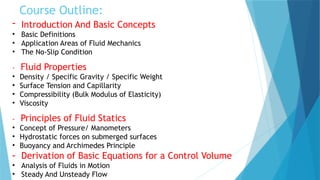
Course Outline:
- IntroductionAnd Basic Concepts
• Basic Definitions
• Application Areas of Fluid Mechanics
• The No-Slip Condition
- Fluid Properties
• Density / Specific Gravity / Specific Weight
• Surface Tension and Capillarity
• Compressibility (Bulk Modulus of Elasticity)
• Viscosity
- Principles of Fluid Statics
• Concept of Pressure/ Manometers
• Hydrostatic forces on submerged surfaces
• Buoyancy and Archimedes Principle
- Derivation of Basic Equations for a Control Volume
• Analysis of Fluids in Motion
• Steady And Unsteady Flow
4.
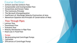
Course Outline:
• UniformAnd Non-Uniform Flow
• Compressible and Incompressible Flow
• Streamlines And Stream Tubes
• The Continuity Principle
• The Bernoulli (Energy)Equation
• Coefficient of; Discharge/Velocity/Contraction of Area
• Momentum Equation And Principle of Conservation of Mass
- Flow Through Pipes
• Laminar flow
• Transitional Flow
• Turbulent flow
• Velocity Distribution in Pipe Flow
• Head Loss in Fluid Flow
- Pumps
• Reciprocating And Centrifugal Pumps
• Cativation
• Efficiences of Centrifugal Pumps
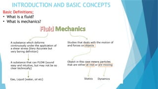
INTRODUCTION AND BASICCONCEPTS
Basic Definitions;
• What is a fluid?
• What is mechanics?
7.
INTRODUCTION AND BASICCONCEPTS
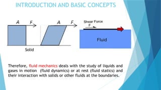
Solid
Therefore, fluid mechanics deals with the study of liquids and
gases in motion (fluid dynamics) or at rest (fluid statics) and
their interaction with solids or other fluids at the boundaries.
8.
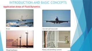
INTRODUCTION AND BASICCONCEPTS
Application Areas of Fluid Dynamics
Fluid mechanics is widely used both in everyday activities and in the
design of modern engineering systems.
Artificial Heart Artificial Lungs
INTRODUCTION AND BASICCONCEPTS
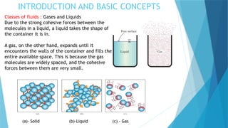
Classes of fluids : Gases and Liquids
Due to the strong cohesive forces between the
molecules in a liquid, a liquid takes the shape of
the container it is in.
A gas, on the other hand, expands until it
encounters the walls of the container and fills the
entire available space. This is because the gas
molecules are widely spaced, and the cohesive
forces between them are very small.
(a)- Solid (b)-Liquid (c) - Gas
11.
INTRODUCTION AND BASICCONCEPTS
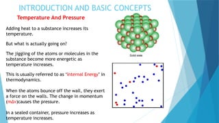
Temperature And Pressure
Adding heat to a substance increases its
temperature.
But what is actually going on?
The jiggling of the atoms or molecules in the
substance become more energetic as
temperature increases.
This is usually referred to as ‘Internal Energy’ in
thermodynamics.
When the atoms bounce off the wall, they exert
a force on the walls. The change in momentum
(m∆ν)causes the pressure.
In a sealed container, pressure increases as
temperature increases.
12.
INTRODUCTION AND BASICCONCEPTS
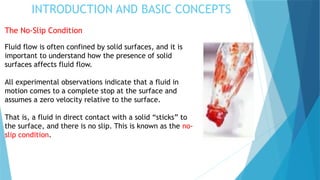
The No-Slip Condition
Fluid flow is often confined by solid surfaces, and it is
important to understand how the presence of solid
surfaces affects fluid flow.
All experimental observations indicate that a fluid in
motion comes to a complete stop at the surface and
assumes a zero velocity relative to the surface.
That is, a fluid in direct contact with a solid “sticks” to
the surface, and there is no slip. This is known as the no-
slip condition.
13.
INTRODUCTION AND BASICCONCEPTS
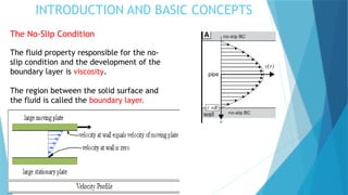
The No-Slip Condition
The fluid property responsible for the no-
slip condition and the development of the
boundary layer is viscosity.
The region between the solid surface and
the fluid is called the boundary layer.
14.
INTRODUCTION AND BASICCONCEPTS
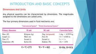
Dimensions And Units
Any physical quantity can be characterized by dimensions. The magnitudes
assigned to the dimensions are called units.
The four primary dimensions used in fluid mechanics are;
15.
INTRODUCTION AND BASICCONCEPTS
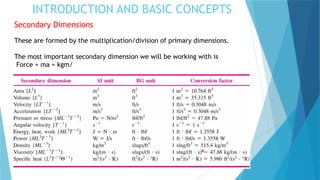
Secondary Dimensions
These are formed by the multiplication/division of primary dimensions.
The most important secondary dimension we will be working with is
Force = ma = kgm/
PROPERTIES OF FLUIDS
Density/SpecificGravity/ Specific Weight
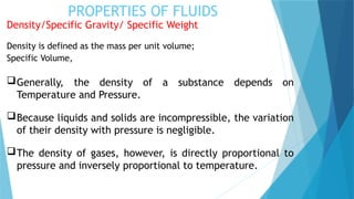
Density is defined as the mass per unit volume;
Specific Volume,
Generally, the density of a substance depends on
Temperature and Pressure.
Because liquids and solids are incompressible, the variation
of their density with pressure is negligible.
The density of gases, however, is directly proportional to
pressure and inversely proportional to temperature.
18.
PROPERTIES OF FLUIDS
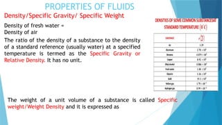
Density/SpecificGravity/ Specific Weight
Density of fresh water =
Density of air
The ratio of the density of a substance to the density
of a standard reference (usually water) at a specified
temperature is termed as the Specific Gravity or
Relative Density. It has no unit.
The weight of a unit volume of a substance is called Specific
weight/Weight Density and it is expressed as
19.
PROPERTIES OF FLUIDS
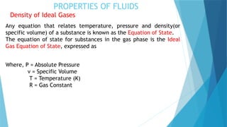
Densityof Ideal Gases
Any equation that relates temperature, pressure and density(or
specific volume) of a substance is known as the Equation of State.
The equation of state for substances in the gas phase is the Ideal
Gas Equation of State, expressed as
Where, P = Absolute Pressure
v = Specific Volume
T = Temperature (K)
R = Gas Constant
20.
Examples
1. A reservoirof glycerin has a mass of 1,200kg and a volume of
300m3. Calculate its density, specific gravity and specific
volume.
2. Calculate the specific weight, density and specific gravity of 1L
of petrol which weighs 7N.
3. The density of a liquid is 2.93g/cm3. What is its specific gravity,
specific volume and specific weight?
4. Calculate the density, specific weight and weight of 1L liquid of
specific gravity 0.8.
5. The specific gravity of ice is 0.9, calculate the weight density of
the ice.
6. The mass of a fluid system is 4kg, its density is 2g/cm3 and
g=9.81m/s2. Determine the Specific volume, Specific weight and
total weight of the fluid.
7. If 25L of an oil weighs 425g, what is the density and specific
gravity of the oil.
21.
Examples
8. If 0.5m3of a liquid has a density of 1.8 g/cm3, what is the
weight of the liquid?
9. What is the volume of a solution that weighs 45N and has a
specific gravity of 0.78?
10. What is the specific weight of air at 48kPa and 21 C. R = 0.287
kPa.m/kg.K.
11. A mass of 150g of argon is maintained at 200 Pa and 100°F in a
tank. What is the volume of the tank?
12. A 100L container is filled with 1 kg of air at a temperature of
27°C. What is the pressure in the container? R = 0.287 kPa.m/kg.K.
13. Determine the density, specific gravity, and mass of the air in a
room whose dimensions are 4 m x 5 m x 6 m at 100 kPa and 25°C. R
= 0.287 kPa.m/kg.K.
22.
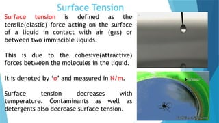
Surface Tension
Surface tensionis defined as the
tensile(elastic) force acting on the surface
of a liquid in contact with air (gas) or
between two immiscible liquids.
This is due to the cohesive(attractive)
forces between the molecules in the liquid.
It is denoted by ‘σ’ and measured in N/m.
Surface tension decreases with
temperature. Contaminants as well as
detergents also decrease surface tension.
23.
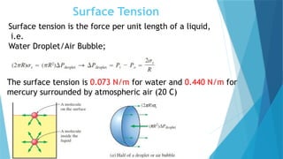
Surface Tension
Surface tensionis the force per unit length of a liquid,
i.e.
Water Droplet/Air Bubble;
The surface tension is 0.073 N/m for water and 0.440 N/m for
mercury surrounded by atmospheric air (20 C)
24.
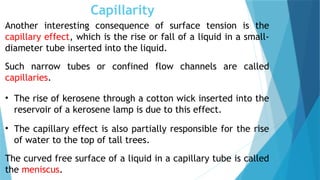
Capillarity
Another interesting consequenceof surface tension is the
capillary effect, which is the rise or fall of a liquid in a small-
diameter tube inserted into the liquid.
Such narrow tubes or confined flow channels are called
capillaries.
• The rise of kerosene through a cotton wick inserted into the
reservoir of a kerosene lamp is due to this effect.
• The capillary effect is also partially responsible for the rise
of water to the top of tall trees.
The curved free surface of a liquid in a capillary tube is called
the meniscus.
25.
Capillarity
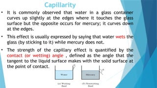
• It iscommonly observed that water in a glass container
curves up slightly at the edges where it touches the glass
surface but the opposite occurs for mercury; it curves down
at the edges.
• This effect is usually expressed by saying that water wets the
glass (by sticking to it) while mercury does not.
• The strength of the capillary effect is quantified by the
contact (or wetting) angle , defined as the angle that the
tangent to the liquid surface makes with the solid surface at
the point of contact.
26.
Capillarity
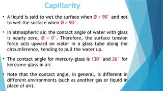
• A liquidis said to wet the surface when Ø < 90° and not
to wet the surface when Ø > 90°.
• In atmospheric air, the contact angle of water with glass
is nearly zero, Ø ≈ 0°. Therefore, the surface tension
force acts upward on water in a glass tube along the
circumference, tending to pull the water up.
• The contact angle for mercury–glass is 130° and 26° for
kerosene–glass in air.
• Note that the contact angle, in general, is different in
different environments (such as another gas or liquid in
place of air).
27.
Capillarity
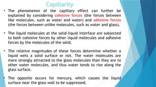
• The phenomenonof the capillary effect can further be
explained by considering cohesive forces (the forces between
like molecules, such as water and water) and adhesive forces
(the forces between unlike molecules, such as water and glass).
• The liquid molecules at the solid–liquid interface are subjected
to both cohesive forces by other liquid molecules and adhesive
forces by the molecules of the solid.
• The relative magnitudes of these forces determine whether a
liquid wets a solid surface or not. The water molecules are
more strongly attracted to the glass molecules than they are to
other water molecules, and thus water tends to rise along the
glass surface.
• The opposite occurs for mercury, which causes the liquid
surface near the glass wall to be suppressed.
28.
Capillarity
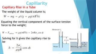
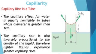
Capillary Rise ina Tube
The weight of the liquid column is;
Equating the vertical component of the surface tension
force to the weight;
Solving for h gives the capillary rise to
be
29.
Capillarity
Capillary Rise ina Tube
• The capillary effect for water
is usually negligible in tubes
whose diameter is greater than
1cm.
• The capillary rise is also
inversely proportional to the
density of the liquid, therefore
lighter liquids experience
greater capillary rises.
30.
Examples
1. Water risesto a height of 4.5cm in a capillary tube of radius r. Find r, assuming
the surface tension of water is 0.073 N/m. Take the angle of contact in the
glass as
2. A liquid of density , rises to a height of 7mm in a capillary tube of internal
diameter 2mm. If the angle of contact of the liquid to the glass is , find the
surface tension of the liquid.
3. A capillary tube of radius 0.05cm is dipped vertically into a liquid of surface
tension 0.04N/m and density 0.8. Calculate the height of capillary rise, if the
angle of contact is
4. A capillary tube 0.12mm in diameter has its lower end immersed in liquid with
density . Calculate the height of capillary rise if σ .
5. Find the angle of contact to a capillary tube of radius 0.0005m, having a
density of 680 Given that the liquid has a surface tension of 0.062 and a
capillary rise is 5.2cm.
31.
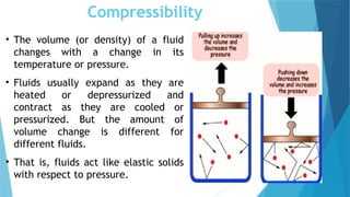
Compressibility
• The volume(or density) of a fluid
changes with a change in its
temperature or pressure.
• Fluids usually expand as they are
heated or depressurized and
contract as they are cooled or
pressurized. But the amount of
volume change is different for
different fluids.
• That is, fluids act like elastic solids
with respect to pressure.
32.
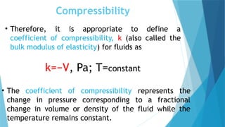
Compressibility
• Therefore, itis appropriate to define a
coefficient of compressibility, k (also called the
bulk modulus of elasticity) for fluids as
k=−V, Pa; T=constant
• The coefficient of compressibility represents the
change in pressure corresponding to a fractional
change in volume or density of the fluid while the
temperature remains constant.
33.
Compressibility
• Bulk Modulusis the measure of ability of a
substance to withstand changes in volume when
it undergoes compression on all sides.
• A large value of ‘k’ indicates that a large change
in pressure is needed to cause a small fractional
change in volume, and thus a fluid with a large
k, is essentially incompressible.
• This is typical for liquids, and explains why
liquids are usually considered to be
incompressible.
34.
Compressibility
• For anideal gas,
;
Therefore,
• Therefore, the coefficient of compressibility of an
ideal gas is equal to its absolute pressure, and so k, of
the gas increases with increasing pressure.
35.
Viscosity
• When twosolid bodies in contact move relative to
each other, a friction force develops at the contact
surface in the direction opposite to motion.
• The situation is similar when a fluid moves relative
to a solid or when two fluids move relative to each
other. We move with ease in air, but not so in water.
• There is a property that represents the internal
resistance of a fluid to motion or the “fluidity,” and
that property is the viscosity.
36.
Viscosity
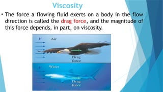
• The forcea flowing fluid exerts on a body in the flow
direction is called the drag force, and the magnitude of
this force depends, in part, on viscosity.
37.
Viscosity
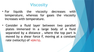
• For liquidsthe viscosity decreases with
temperature, whereas for gases the viscosity
increases with temperature.
• Consider a fluid layer between two parallel
plates immersed in a large body of a fluid
separated by a distance , where the top part is
moved by a shear force F, moving at a constant
rate (velocity) of ν(m/s).
38.
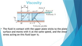
Viscosity
• The fluidin contact with the upper plate sticks to the plate
surface and moves with it at the same speed, and the shear
stress acting on this fluid layer is;
39.
Viscosity
• The rateof deformation or change in velocity increases
with distance above the fixed plate. Hence
Where the constant of proprotionality is known as the
dynamic/absolute viscosity.
Therefore dynamic/absolute viscosity of a fluid is the
measure of its internal resistance to flow when an
external force is applied. Unit is Pa.s or cP
40.
Viscosity
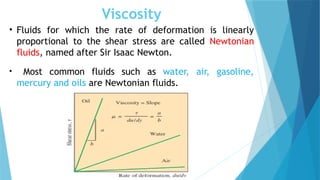
• Fluids forwhich the rate of deformation is linearly
proportional to the shear stress are called Newtonian
fluids, named after Sir Isaac Newton.
• Most common fluids such as water, air, gasoline,
mercury and oils are Newtonian fluids.
41.
Viscosity
For non-Newtonian fluids,the relationship
between shear stress and rate of deformation is
not linear.
Examples : Blood, toothpaste, ketchup, some
paints,liquid plastics, etc.
The ratio of dynamic viscosity to density is
referred to as Kinematic viscosity (), expressed as;
,
Concept of Pressure
Pressure is defined as a normal force exerted by a
fluid per unit area.
P =
We speak of pressure only when we deal with a gas
or a liquid. The counterpart of pressure in solids is
normal stress.
Since pressure is defined as force per unit area, it
has the unit of newtons per square meter (), which is
called a Pascal (Pa).
44.
Concept of Pressure
That is,
The pressure unit Pascal is too small for most pressures
encountered in practice. Therefore, its multiples are
commonly used; i.e.
1 KiloPascal (kPa) =
1 MegaPascal (MPa) =
1 bar =
1 atm = 101,325
45.
Concept of Pressure
•The air above the earth’s surface is a fluid, which
exerts a pressure on all points on the earth’s surface.
This pressure is called atmospheric pressure.
• The actual pressure at a given position is called the
absolute pressure, and it is measured relative to
absolute zero/vacuum.
• Most pressure-measuring devices, however, are
calibrated to read zero in the atmosphere and so they
indicate the difference between the absolute pressure
and the local atmospheric pressure.
• This difference is called the gauge pressure.
46.
Concept of Pressure
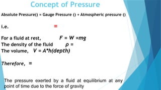
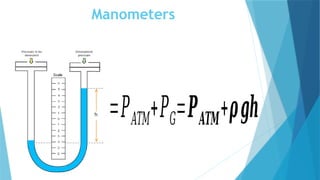
AbsolutePressure() = Gauge Pressure () + Atmospheric pressure ()
i.e. =
For a fluid at rest, F = W =mg
The density of the fluid ρ =
The volume, V = A*h(depth)
Therefore, =
The pressure exerted by a fluid at equilibrium at any
point of time due to the force of gravity
47.
Concept of Pressure
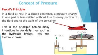
Pascal’sPrinciple
In a fluid at rest in a closed container, a pressure change
in one part is transmitted without loss to every portion of
the fluid and to the walls of the container.
This is the principle behind many
inventions in our daily lives such as
the hydraulic brakes, lifts and
hydraulic press.
48.
Concept of Pressure
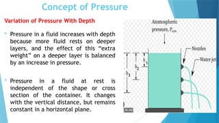
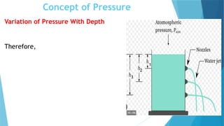
Variationof Pressure With Depth
Pressure in a fluid increases with depth
because more fluid rests on deeper
layers, and the effect of this “extra
weight” on a deeper layer is balanced
by an increase in pressure.
Pressure in a fluid at rest is
independent of the shape or cross
section of the container. It changes
with the vertical distance, but remains
constant in a horizontal plane.
3
2
1
Concept of Pressure
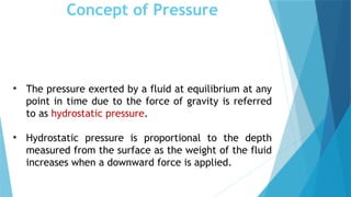
•The pressure exerted by a fluid at equilibrium at any
point in time due to the force of gravity is referred
to as hydrostatic pressure.
• Hydrostatic pressure is proportional to the depth
measured from the surface as the weight of the fluid
increases when a downward force is applied.
51.
Barometers
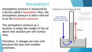
Atmospheric pressure ismeasured by
a device called a barometer; thus, the
atmospheric pressure is often referred
to as the barometric pressure.
The atmospheric pressure at a
location is simply the weight of the air
above that location per unit surface
area.
Therefore, it changes not only with
elevation but also with weather
conditions.
52.
Manometers
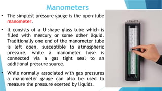
• The simplestpressure gauge is the open-tube
manometer.
• It consists of a U-shape glass tube which is
filled with mercury or some other liquid.
Traditionally one end of the manometer tube
is left open, susceptible to atmospheric
pressure, while a manometer hose is
connected via a gas tight seal to an
additional pressure source.
• While normally associated with gas pressures
a manometer gauge can also be used to
measure the pressure exerted by liquids.
53.
Manometers
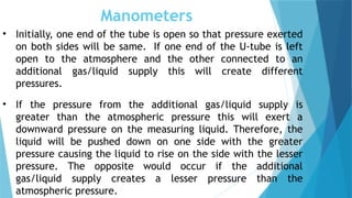
• Initially, oneend of the tube is open so that pressure exerted
on both sides will be same. If one end of the U-tube is left
open to the atmosphere and the other connected to an
additional gas/liquid supply this will create different
pressures.
• If the pressure from the additional gas/liquid supply is
greater than the atmospheric pressure this will exert a
downward pressure on the measuring liquid. Therefore, the
liquid will be pushed down on one side with the greater
pressure causing the liquid to rise on the side with the lesser
pressure. The opposite would occur if the additional
gas/liquid supply creates a lesser pressure than the
atmospheric pressure.
54.
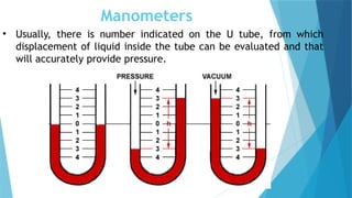
Manometers
• Usually, thereis number indicated on the U tube, from which
displacement of liquid inside the tube can be evaluated and that
will accurately provide pressure.
Hydrostatic Forces onSubmerged
Surfaces
Fluid statics deals with problems associated with fluids
at rest.
Fluid statics is generally referred to as hydrostatics
when the fluid is a liquid and as aerostatics when the
fluid is a gas.
Hydrostatics is the branch of physics that deals with
the characteristics of fluids at rest, particularly with
the pressure in a fluid or exerted by a fluid on an
immersed body.
57.
Hydrostatic Forces onSubmerged
Surfaces
The design of many engineering systems such as water
dams and liquid storage tanks requires the
determination of the forces acting on their surfaces
using fluid statics.
The complete description of the resultant hydrostatic
force acting on a submerged surface requires the
determination of the magnitude, the direction, and the
line of action of the force.
58.
Hydrostatic Forces onSubmerged
Surfaces
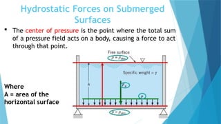
The center of pressure is the point where the total sum
of a pressure field acts on a body, causing a force to act
through that point.
Where
A = area of the
horizontal surface
BUOYANCY
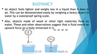
An objectfeels lighter and weighs less in a liquid than it does in
air. This can be demonstrated easily by weighing a heavy object in
water by a waterproof spring scale.
Also, objects made of wood or other light materials float on
water. These and other observations suggest that a fluid exerts an
upward force on a body immersed in it.
63.
BUOYANCY
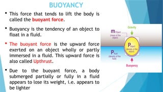
This forcethat tends to lift the body is
called the buoyant force.
Buoyancy is the tendency of an object to
float in a fluid.
The buoyant force is the upward force
exerted on an object wholly or partly
immersed in a fluid. This upward force is
also called Upthrust.
Due to the buoyant force, a body
submerged partially or fully in a fluid
appears to lose its weight, i.e. appears to
be lighter
64.
BUOYANCY
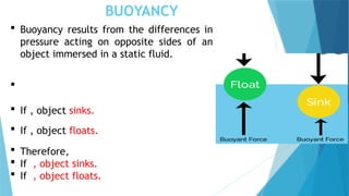
Buoyancy resultsfrom the differences in
pressure acting on opposite sides of an
object immersed in a static fluid.
If , object sinks.
If , object floats.
Therefore,
If , object sinks.
If , object floats.
BUOYANCY
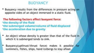
Buoyancy resultsfrom the differences in pressure acting on
opposite sides of an object immersed in a static fluid.
The following factors affect buoyant force:
•the density of the fluid
•the submerged volume/volume of fluid displaced
•the acceleration due to gravity
An object whose density is greater than that of the fluid in
which it is submerged tends to sink.
Buoyancy(upthrust/thrust force) makes it possible for
swimmers, fishes, ships, hand icebergs to stay afloat.
67.
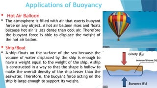
Applications of Buoyancy
Hot Air Balloon
The atmosphere is filled with air that exerts buoyant
force on any object. A hot air balloon rises and floats
because hot air is less dense than cool air. Therefore
the buoyant force is able to displace the weight of
the hot air ballon.
Ship/Boat
A ship floats on the surface of the sea because the
volume of water displaced by the ship is enough to
have a weight equal to the weight of the ship. A ship
is constructed in a way so that the shape is hollow to
make the overall density of the ship lesser than the
seawater. Therefore, the buoyant force acting on the
ship is large enough to support its weight.
68.
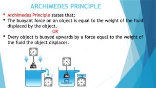
ARCHIMEDES PRINCIPLE
ArchimedesPrinciple states that;
The buoyant force on an object is equal to the weight of the fluid
displaced by the object.
OR
Every object is buoyed upwards by a force equal to the weight of
the fluid the object displaces.
69.
ARCHIMEDES PRINCIPLE
Thismeans that if you want to know the buoyant force on
an object, you only need to determine the weight of the
fluid displaced by the object.
Apparent weight =
70.
ARCHIMEDES PRINCIPLE
Archimedesprinciple helps us to determine the volume of
an irregular object.
Therefore if the object is completely submerged in the fluid,
the volume of the displaced fluid equals the volume of the
object.
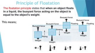
Principle of Floatation
Thefloatation principle states that when an object floats
in a liquid, the buoyant force acting on the object is
equal to the object's weight.
This means;
73.
Examples
1. A blockof wood with length 50cm and width 30cm is placed in water. If
the 10cm of the total height of the wood is immersed in the water,
calculate the buoyant force on the wood. []
2. A cube with a side length of 5cm is submerged in oil. What is the buoyant
force on the cube if the density of the oil is 896 kg/.
3. The weight of an object in air is 10N. When it is submerged in a liquid of
relative density 1.15, the volume of the liquid increased from 15cm to
20cm. What is the weight of the object in water?
4. A concrete slab weighs 150 N. When it is fully submerged under the sea,
its apparent weight is 102 N. Calculate the density of the sea water if
the volume of the sea water displaced by the concrete slab is 4800 cm3
,
[g = 9.8 m/s2 ]
5. You plunge a basketball beneath the surface of a swimming pool until
half the volume of the basketball is submerged. If the basketball has a
radius of 12 cm, what is the buoyancy force on the ball due to the
water? []
74.
Examples Contd
1. Thevolume of a 500g sealed packet is 350cm3. Will the packet sink or
float? What is the mass of displaced by the packet. []
2. A block of wood with the dimensions 0.12 by 0.34 by 0.43 cubic meters
floats along a river with the broadest face facing down. The wood is
submerged to a height of 0.053 meters. What is the mass of the piece of
wood? []
3. Gold, whose mass is 193g is fully submerged in kerosene having an
upward force of 8N. If the density of kerosene is 0.8kg/, find the
density of the gold.
4. A boat is loaded with some goods floating on the sea with water
displacement of 1.5m3. If the density of the seawater is 1020kg/m3,
calculate the additional weight of goods to be added to displace 4.5m3
of seawater.
5. A piece of aluminium with a mass of 1kg and relative density of 2.7 is
suspended from a string and then completely immersed in water.
Determine the volume of the piece of aluminium and the tension in the
string after immersion. []
Analysis of Fluidsin Motion
Fluid Dynamics is a subdiscipline of fluid mechanics that
describes the flow of fluids (i.e. liquids and gases).
The study of air and other gases in motion is called
aerodynamics.
The study of liquids in motion is referred to as
hydrodynamics.
Some of the important technological applications of fluid
dynamics include meteorology, rocket engines, wind
turbines, oil pipelines, and air conditioning systems.
77.
Types Of Flow
SteadyAnd Unsteady Flow
A steady flow is one in which the conditions/parameters
(velocity, pressure, density, acceleration, etc) at a point
do not change with time.
If at any point in the fluid, the conditions (velocity,
pressure, density, acceleration, etc) change with time,
the flow is described as unsteady.
78.
Uniform And Non-UniformFlow
If the velocity at a given instant of time is same in both
magnitude and direction at all points in the flow, the
flow is said to be uniform flow.
When the velocity changes from point to point in a flow
at any given instant of time, the flow is described as non-
uniform flow.
79.
Compressible and IncompressibleFlow
The flow in which density of the fluid varies during the flow
is called compressible fluid flow. (i. e. ). This is
applicable in gas flow.
Incompressible fluid flow is when the density of the fluid
remains the constant during the flow (i.e. ρ=constant).
Practically,all liquids are treated as incompressible.
80.
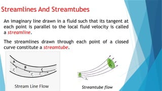
Streamlines And Streamtubes
Animaginary line drawn in a fluid such that its tangent at
each point is parallel to the local fluid velocity is called
a streamline.
The streamlines drawn through each point of a closed
curve constitute a streamtube.
Streamtube flow
81.
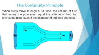
The Continuity Principle
Whenfluids move through a full pipe, the volume of fluid
that enters the pipe must equal the volume of fluid that
leaves the pipe, even if the diameter of the pipe changes.
82.
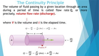
The Continuity Principle
Thevolume of fluid passing by a given location through an area
during a period of time is called flow rate Q, or more
precisely, volume flow rate (discharge).
;
where V is the volume and t is the elapsed time.
83.
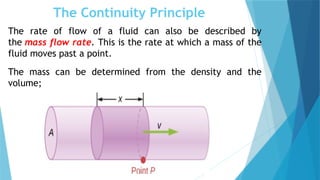
The Continuity Principle
Therate of flow of a fluid can also be described by
the mass flow rate. This is the rate at which a mass of the
fluid moves past a point.
The mass can be determined from the density and the
volume;
84.
The Continuity Principle
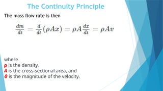
Themass flow rate is then
where
ρ is the density,
A is the cross-sectional area, and
ϑ is the magnitude of the velocity.
85.
The Continuity Principle
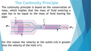
Thecontinuity principle is based on the conservation of
mass, which implies that the mass of fluid entering a
pipe has to be equal to the mass of fluid leaving the
pipe.
For this reason the velocity at the outlet (v2) is greater
than the velocity of the inlet (v1).
𝝆𝟏
𝝆𝟐
86.
The Continuity Principle
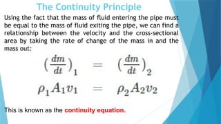
Usingthe fact that the mass of fluid entering the pipe must
be equal to the mass of fluid exiting the pipe, we can find a
relationship between the velocity and the cross-sectional
area by taking the rate of change of the mass in and the
mass out:
This is known as the continuity equation.
87.
The Continuity Principle
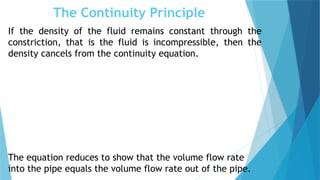
Ifthe density of the fluid remains constant through the
constriction, that is the fluid is incompressible, then the
density cancels from the continuity equation.
The equation reduces to show that the volume flow rate
into the pipe equals the volume flow rate out of the pipe.
88.
The Bernoulli Principle
Bernoulli’sprinciple formulated by Daniel Bernoulli states
that as the speed of a moving fluid increases, the pressure
within the fluid decreases.
Energy can neither be produced nor destroyed but only
transformed.
Therefore, Bernoulli’s Principle based on conservation of
energy states that in a steady ideal flow of incompressible
fluid, the sum of pressure energy, kinetic energy and
potential energy remains constant at every section
provided no energy is added or taken out by an external
source.
89.
The Bernoulli Principle
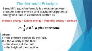
Pressureenergy + Kinetic energy + Potential energy = constant
𝑷+
𝟏
𝟐
𝝆 𝝑
𝟐
+𝝆 𝒈𝒉=𝒄𝒐𝒏𝒔𝒕𝒂𝒏𝒕
Where;
p = the pressure exerted by the fluid,
ϑ = the velocity of the fluid,
ρ = the density of the fluid
h = the height of the container.
Bernoulli’s equation formula is a relation between
pressure, kinetic energy, and gravitational potential
energy of a fluid in a container, written as;
90.
The Bernoulli Principle
ForBernoulli’s equation to be applied, the following
assumptions must be met:
The flow must be steady. (Velocity, pressure and density
cannot change at any point).
The flow must be incompressible – even when the
pressure varies, the density must remain constant along
the streamline.
Friction by viscous forces must be minimal.
91.
Bernoulli equation applicationin fluid mechanics
The Bernoulli equation is applied to all incompressible fluid flow
problems. The Bernoulli equation can be applied to devices such as
the orifice meter, Venturi meter, and Pitot tube and its applications
for measuring flow in open channels and inside tubes.
92.
Hydraulic Coefficients
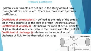
Hydraulic coefficientsare defined in the study of fluid flow
through orifices, nozzle, etc.. There are three main hydraulic
coefficients;
Coefficient of contraction () - defined as the ratio of the area of
jet at Vena contracta to the area of orifice (theoretical area).
Coefficient of velocity () - defined as the ratio of actual velocity
of jet of fluid at vena-contracta to the theoretical velocity of jet.
Coefficient of discharge () - defined as the ratio of actual
discharge of fluid to the theoretical discharge.
93.
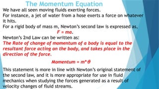
The Momentum Equation
Wehave all seen moving fluids exerting forces.
For instance, a jet of water from a hose exerts a force on whatever
it hits.
For a rigid body of mass m, Newton’s second law is expressed as,
F = ma.
Newton’s 2nd Law can be written as:
The Rate of change of momentum of a body is equal to the
resultant force acting on the body, and takes place in the
direction of the force.
Momentum = m*ϑ
This statement is more in line with Newton’s original statement of
the second law, and it is more appropriate for use in fluid
mechanics when studying the forces generated as a result of
velocity changes of fluid streams.
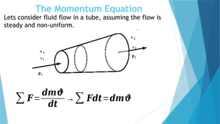
The Momentum Equation
Letsconsider fluid flow in a tube, assuming the flow is
steady and non-uniform.
∑ 𝑭=
𝒅𝒎𝝑
𝒅𝒕
→∑ 𝑭𝒅𝒕=𝒅𝒎𝝑
96.
The Momentum Equation
Volumeof fluid entering the tube with time =
however, the velocity, = *
mass of fluid entering the tube =
Momentum of fluid entering tube = mass * velocity
=
Similarly, at the exit, we obtain the momentum of fluid leaving
the tube =
This means;
Examples
1. Calculate theflow rate of fluid if it is moving with the velocity of
20 m/s through a tube of diameter 0.03 m.
2. A pipe has an initial cross-sectional area of 2 cm2
that expands
into a 5 cm2
area. Initially, the velocity of the water through the
smaller cross-sectional area of the pipe is 20 m/s. Determine the
velocity of the water through the larger cross-sectional area
section of the pipe.
3. Water flows through a storage tank of radius 15cm with a velocity
of 1.5m/s into a storage tank. Calculate the mass flow rate.
4. Determine the resultant force needed to move a fluid of relative
density 0.87 from 2m/s to 5m/s at a rate of 3 m3
/s
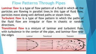
Flow Patterns ThroughPipes
Laminar flow is a type of flow pattern of a fluid in which all the
particles are flowing in parallel lines.In this type of fluid flow,
particles move along well defined paths or steam lines.
Turbulent flow is a type of flow pattern in which the paths of
the fluid flow are irregular or flow in chaotic or random
directions.
Transitional flow is a mixture of laminar and turbulent flow,
with turbulence in the center of the pipe, and laminar flow near
the edges.
101.
Flow Patterns ThroughPipes
The flow pattern can be determined using the Reynolds
Number, Re.
Where = density of fluid
= velocity of flow
D = diameter of pipe
= dynamic viscosity of fluid
Re < 2100 = laminar flow
2100 < Re < 4000 = transitional flow
Re > 4000 = turbulent flow
102.
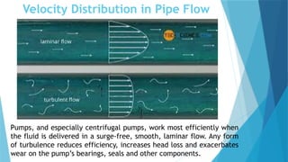
Velocity Distribution inPipe Flow
Not all fluid particles travel with the same velocity
within a pipe.
The shape of the velocity curve depends on whether the
flow is laminar or turbulent.
If the flow in a pipe is laminar, the velocity distribution
at a cross section will be parabolic in shape with the
maximum velocity being t the center which is twice the
average velocity in the pipe.
In turbulent flow, a fairly flat velocity distribution exists
across the section of pipe with result that the entire
fluid flows at a given single value.
103.
Velocity Distribution inPipe Flow
Pumps, and especially centrifugal pumps, work most efficiently when
the fluid is delivered in a surge-free, smooth, laminar flow. Any form
of turbulence reduces efficiency, increases head loss and exacerbates
wear on the pump’s bearings, seals and other components.
104.
Head Loss InFluid Flow
The term pipe flow is generally used to describe flow
through round pipes, ducts, nozzles, sudden
expansions and contractions, valves and other fittings.
When a gas or a liquid flows through a pipe, there is a
loss of pressure in the fluid, because energy is
required to overcome the viscous or frictional forces
exerted by the walls of the pipe on the moving fluid.
In addition to the energy lost due to frictional forces,
the flow also loses energy (or pressure) as it goes
through fittings, such as valves, elbows, contractions
and expansions.
105.
Head Loss InFluid Flow
The pressure loss in pipe flows is commonly referred to
as head loss.
The frictional losses are referred to as major losses
(Hf) while losses through fittings,valves etc, are
called minor losses (Hm).
Together they make up the total head losses (HT) for
pipe flows.
The head loss due to the friction (Hf) in a given pipeline
for a given discharge is determined by the Darcy-
Weisbach equation:
106.
Head Loss InFluid Flow
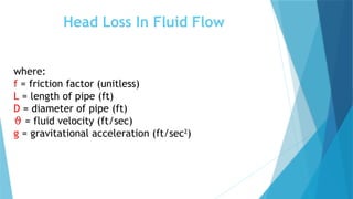
where:
f = friction factor (unitless)
L = length of pipe (ft)
D = diameter of pipe (ft)
ϑ = fluid velocity (ft/sec)
g = gravitational acceleration (ft/sec2
)
107.
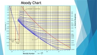
Head Loss InFluid Flow
The friction factor can be determined by the
Moody Chart.
The friction factor is characterized by;
Flow regime (Reynolds Number)
Relative roughness
Pipe cross-section
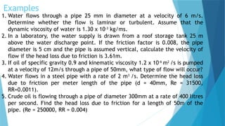
Examples
1. Water flowsthrough a pipe 25 mm in diameter at a velocity of 6 m/s.
Determine whether the flow is laminar or turbulent. Assume that the
dynamic viscosity of water is 1.30 x 10⁻³
kg/ms.
2. In a laboratory, the water supply is drawn from a roof storage tank 25 m
above the water discharge point. If the friction factor is 0.008, the pipe
diameter is 5 cm and the pipe is assumed vertical, calculate the velocity of
flow if the head loss due to friction is 3.61m.
3. If oil of specific gravity 0.9 and kinematic viscosity 1.2 x 10⁻⁶
m2
/s is pumped
at a velocity of 12m/s through a pipe of 50mm, what type of flow will occur?
4. Water flows in a steel pipe with a rate of 2 m3
/s. Determine the head loss
due to friction per meter length of the pipe (d = 40mm, Re = 31500,
RR=0.0011).
5. Crude oil is flowing through a pipe of diameter 300mm at a rate of 400 litres
per second. Find the head loss due to friction for a length of 50m of the
pipe. (Re = 250000, RR = 0.004)
Pumps
Pumps areused to transfer and distribute liquids in various
industries. Pumps convert mechanical energy into hydraulic
energy. Electrical energy is generally used to operate the various
types of pumps.
Pumps have two main purposes.
Transfer of liquid from one place to another place (e.g. water
from an underground into a water storage tank).
Circulate liquid around a system (e.g. cooling water or
lubricants through machines and equipment).
112.
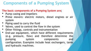
Components of aPumping System
The basic components of a Pumping System are;
Pump casing and impellers
Prime movers: electric motors, diesel engines or air
system
Piping used to carry the fluid
Valves, used to control the flow in the system
Other fittings, controls and instrumentation
End-use equipment, which have different requirements
(e.g. pressure, flow) and therefore determine the
pumping system components and
configuration. Examples include heat exchangers, tanks
and hydraulic machines.
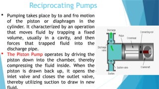
Reciprocating Pumps
Pumpingtakes place by to and fro motion
of the piston or diaphragm in the
cylinder. It characterized by an operation
that moves fluid by trapping a fixed
volume, usually in a cavity, and then
forces that trapped fluid into the
discharge pipe.
The Piston Pump operates by driving the
piston down into the chamber, thereby
compressing the fluid inside. When the
piston is drawn back up, it opens the
inlet valve and closes the outlet valve,
thereby utilizing suction to draw in new
115.
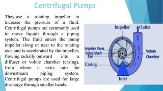
Centrifugal Pumps
They usea rotating impeller to
increase the pressure of a fluid.
Centrifugal pumps are commonly used
to move liquids through a piping
system. The fluid enters the pump
impeller along or near to the rotating
axis and is accelerated by the impeller,
flowing radially outward into a
diffuser or volute chamber (casing),
from where it exits into the
downstream piping system.
Centrifugal pumps are used for large
discharge through smaller heads.
116.
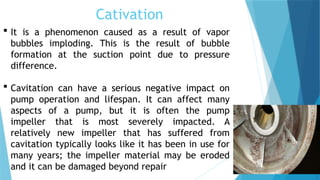
Cativation
It isa phenomenon caused as a result of vapor
bubbles imploding. This is the result of bubble
formation at the suction point due to pressure
difference.
Cavitation can have a serious negative impact on
pump operation and lifespan. It can affect many
aspects of a pump, but it is often the pump
impeller that is most severely impacted. A
relatively new impeller that has suffered from
cavitation typically looks like it has been in use for
many years; the impeller material may be eroded
and it can be damaged beyond repair
117.
Efficiencies of CentrifugalPumps
Pump efficiency, η (%) is a measure of the efficiency
with which the pump uses the input power to convert
the energy into useful output.
η % = Pout/Pin
where
η = efficiency (%)
Pin = power input
Pout = power output
Pump input or brake horsepower (BHP) is the actual
horsepower delivered to the pump shaft.
Pump output or hydraulic or water horsepower (WHP) is
the liquid horsepower delivered by the pump.
118.
Efficiencies of CentrifugalPumps
These two terms are defined by the following formulas;
where:
BHP is the brake horse power required (Watts)
WHP is the water horse power (Watts)
ρ is the fluid density (kg/m3
)
g is the standard acceleration of gravity (9.81 m/s2
)
H is the energy Head added to the flow (m)
Q is the flow rate (m3
/s)
η is the efficiency of the pump (decimal)


![Examples
1. A block of wood with length 50cm and width 30cm is placed in water. If
the 10cm of the total height of the wood is immersed in the water,
calculate the buoyant force on the wood. []
2. A cube with a side length of 5cm is submerged in oil. What is the buoyant
force on the cube if the density of the oil is 896 kg/.
3. The weight of an object in air is 10N. When it is submerged in a liquid of
relative density 1.15, the volume of the liquid increased from 15cm to
20cm. What is the weight of the object in water?
4. A concrete slab weighs 150 N. When it is fully submerged under the sea,
its apparent weight is 102 N. Calculate the density of the sea water if
the volume of the sea water displaced by the concrete slab is 4800 cm3
,
[g = 9.8 m/s2 ]
5. You plunge a basketball beneath the surface of a swimming pool until
half the volume of the basketball is submerged. If the basketball has a
radius of 12 cm, what is the buoyancy force on the ball due to the
water? []](https://image.slidesharecdn.com/fluidmechanics-dmeupdated1-copy-250309202715-948b9786/85/FLUID-MECHANICS-DME-UPDATED-1-Copy-pptx-73-320.jpg)
![Examples Contd
1. The volume of a 500g sealed packet is 350cm3. Will the packet sink or
float? What is the mass of displaced by the packet. []
2. A block of wood with the dimensions 0.12 by 0.34 by 0.43 cubic meters
floats along a river with the broadest face facing down. The wood is
submerged to a height of 0.053 meters. What is the mass of the piece of
wood? []
3. Gold, whose mass is 193g is fully submerged in kerosene having an
upward force of 8N. If the density of kerosene is 0.8kg/, find the
density of the gold.
4. A boat is loaded with some goods floating on the sea with water
displacement of 1.5m3. If the density of the seawater is 1020kg/m3,
calculate the additional weight of goods to be added to displace 4.5m3
of seawater.
5. A piece of aluminium with a mass of 1kg and relative density of 2.7 is
suspended from a string and then completely immersed in water.
Determine the volume of the piece of aluminium and the tension in the
string after immersion. []](https://image.slidesharecdn.com/fluidmechanics-dmeupdated1-copy-250309202715-948b9786/85/FLUID-MECHANICS-DME-UPDATED-1-Copy-pptx-74-320.jpg)