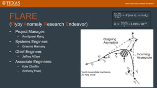
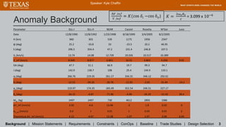
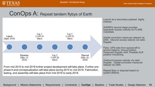
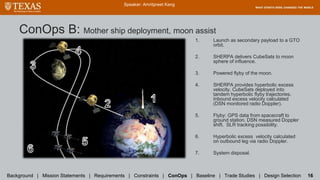
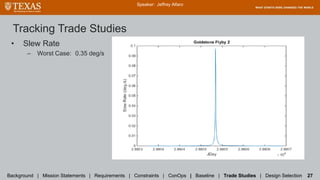
Team FLARE proposes a CubeSat mission to investigate the flyby anomaly experienced by spacecraft performing Earth flybys. The mission would involve launching two 6U CubeSats on a rideshare as secondary payloads. A SHERPA vehicle would deploy the CubeSats and provide excess velocity for hyperbolic flybys of Earth. During flybys, the CubeSats would track their velocity using GPS and ground stations would measure Doppler shifts. The goal is to obtain at least 4 data points to characterize the anomaly. Requirements include measuring velocity changes of 0.1 mm/s accuracy during closest approach and performing tandem flybys.


![Heritage Mission Data Acquisition Overview
Heritage missions navigation precision details [24-26, 26].
• Instruments used on heritage missions to obtain velocity data.
• With these instruments, NEAR measured the highest change in hyperbolic excess
velocity, whereas Juno measured no apparent change.
• Uniquely, Juno incorporated 50x50 and 100x100 gravitational modeling, leading to
mismatch between expected and apparent anomaly, in fact no apparent anomaly [36].
• Explanations of the flyby anomaly focus on modeling errors:
• Higher order gravity terms
• Anisotropy of the speed of light
Background | Mission Statements | Requirements | Constraints | ConOps | Baseline | Trade Studies | Design Selection 4
Speaker: Kyle Chaffin](https://image.slidesharecdn.com/bba913b3-85ca-43e7-9d84-70dbdf5a5a01-150527022222-lva1-app6892/85/FLARE-Final-Presentation-no-animations-6-320.jpg)
![Dominate Anomaly Sources: (JUNO) High Order Gravity
Terms and Anisotropy of the Speed of Light
• HOGT: Truncation in Earth’s geopotential model is actually a perturbation
capable of producing something detectable in real time comparable to the
predicted flyby anomaly [36].
• ASL: The flyby anomalies result from the assumption that the speed of
light is isotropic in all frames, but the speed of light is not invariant and
isotropic only with respect to a dynamical 3-space [44].
Background | Mission Statements | Requirements | Constraints | ConOps | Baseline | Trade Studies | Design Selection 5
Speaker: Kyle Chaffin and Graeme Ramsey](https://image.slidesharecdn.com/bba913b3-85ca-43e7-9d84-70dbdf5a5a01-150527022222-lva1-app6892/85/FLARE-Final-Presentation-no-animations-7-320.jpg)
![Dominate Anomaly Sources: (JUNO) High Order Gravity
Terms and Anisotropy of the Speed of Light
Background | Mission Statements | Requirements | Constraints | ConOps | Baseline | Trade Studies | Design Selection 5
Speaker: Kyle Chaffin and Graeme Ramsey
JUNO Doppler postfit residuals reconstruction (left) and deleted data (right) [36].](https://image.slidesharecdn.com/bba913b3-85ca-43e7-9d84-70dbdf5a5a01-150527022222-lva1-app6892/85/FLARE-Final-Presentation-no-animations-8-320.jpg)
![Background | Mission Statements | Requirements | Constraints | ConOps | Baseline | Trade Studies | Design Selection 5
Dominate Anomaly Sources: (JUNO) High Order Gravity
Speaker: Kyle Chaffin and Graeme Ramsey
Simulated Doppler residuals from 7 mm/s anomaly with (left) and without (right) spin signature [36]](https://image.slidesharecdn.com/bba913b3-85ca-43e7-9d84-70dbdf5a5a01-150527022222-lva1-app6892/85/FLARE-Final-Presentation-no-animations-9-320.jpg)
![Speaker: Kyle Chaffin and Graeme Ramsey
Position (top) and Velocity
(bottom) perturbations
incurred by modeling with
higher order gravity
models than 10X10 [36].
The order of this
perturbation is comparable
to that of the anomaly.](https://image.slidesharecdn.com/bba913b3-85ca-43e7-9d84-70dbdf5a5a01-150527022222-lva1-app6892/85/FLARE-Final-Presentation-no-animations-10-320.jpg)
![Phenomenological Formulae and Perturbation Magnitudes
Background | Mission Statements | Requirements | Constraints | ConOps | Baseline | Trade Studies | Design Selection 6
Speaker: Kyle Chaffin and Graeme Ramsey
𝐾 =
2ω 𝑒 𝑅 𝑒
𝑐
= 3.099 x 10⁻⁶
• Primary formula [1]
• Developed by: JPL (Anderson et al.
2008)
• Effective range: 500 to 2000 km
• Error: same as secondary formula
Magnitude of pertinent accelerations, courtesy
of a Portuguese mission proposal [39].
• Secondary formula [44]
• Developed by: Stephen Adler,
Institute for Advanced Study
• Similar range, see error table](https://image.slidesharecdn.com/bba913b3-85ca-43e7-9d84-70dbdf5a5a01-150527022222-lva1-app6892/85/FLARE-Final-Presentation-no-animations-11-320.jpg)
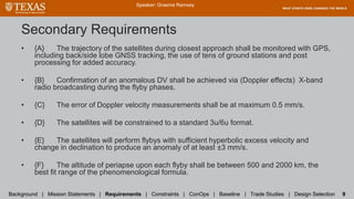
![Primary Requirements
• [A] The system shall be capable of gathering the velocity profile during the inbound and
outbound legs of a hyperbolic flyby trajectory of Earth.
• [B] This project will provide at least 4 velocity profiles associated with the flyby
phenomenon in its projected lifetime.
• [C] The system shall be capable of tracking the velocity the satellite experiencing the
hyperbolic flyby anomaly during closest approach on the order of 0.1 mm/s accuracy.
• [D] The mission design shall perform velocity data collection on “paired” flybys (with
minimal separation) at the above mentioned accuracy (~0.1 mm/s), including coverage
throughout closest approach.
Speaker: Graeme Ramsey
Background | Mission Statements | Requirements | Constraints | ConOps | Baseline | Trade Studies | Design Selection 8](https://image.slidesharecdn.com/bba913b3-85ca-43e7-9d84-70dbdf5a5a01-150527022222-lva1-app6892/85/FLARE-Final-Presentation-no-animations-13-320.jpg)
![Requirements Traceability
Speaker: Graeme Ramsey
Background | Mission Statements | Requirements | Constraints | ConOps | Baseline | Trade Studies | Design Selection 10
Items after [extra] are requirements that weren’t explicitly listed.
Traceability Matrix Relationship: X=direct O=indirect
Primary Mission
Primary V_inf accuracy 4 data pnts V accuracy Tandem sats Budget Mission Assurance Trajectory
Requirement [A] [B] [C] [D] [extra]
System GNSS {A} O X X
Doppler DSN {B} X O
Doppler error {C} X X X X
Sat Size {D} O X
Predicted anomaly {E} O X X
Altitude of periapse {F} X O X X](https://image.slidesharecdn.com/bba913b3-85ca-43e7-9d84-70dbdf5a5a01-150527022222-lva1-app6892/85/FLARE-Final-Presentation-no-animations-15-320.jpg)

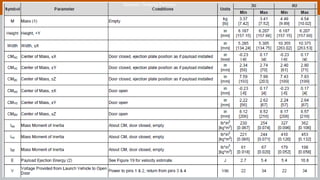
![Constraints
• Projected satellite lifetime: 3 years.
– Radiation toll and propulsion capacity.
– 250-300 m/s DV corrections capable with 4u worth of hydrazine propulsion.
• (optional) cold gas attitude thrusters, desaturation maneuvers for reaction wheals.
– Medium to High TRL and rad hardened subsystem components only.
• Mission budget: $5mil before launch associated costs.
• Secondary payload considerations.
– Satellites must be compatible with a Planetary Systems CSD.
– Satellite mass: 12 kg CSD constraint. Max satellite volume: 6u.
• Launch window and parking orbit/exit trajectory characteristics.
– High eccentricity and inclination, Molniya type parking orbit (considering baseline trajectory.) [Primary ConOps]
– GTO parking orbit option. More ride sharing possibilities. [Secondary ConOps]
• Flyby characteristics must coincide with phenomenological formula.
• SHERPA must be compatible with the launch vehicle.
Speaker: Graeme Ramsey
Background | Mission Statements | Requirements | Constraints | ConOps | Baseline | Trade Studies | Design Selection 11](https://image.slidesharecdn.com/bba913b3-85ca-43e7-9d84-70dbdf5a5a01-150527022222-lva1-app6892/85/FLARE-Final-Presentation-no-animations-17-320.jpg)
![• CSD [4]
• 3.4 kg in mass
• X and Y dimensions: 26.34 cm and 15.75 cm
• Ejection plate force on payload from launch vibration: 0-191 N
• Ejection plate force on payload from spring ejection: 15.6-46.7 N
• Survival temperature extrema: -50 to 100 °C
• Operational temperature extrema: -45 to 90 °C
• Life: 50 door closures
• Payload [27]
• 12 kg max
• Tab lengths: X = 23.92 cm, Z = 36.5 cm
• Force from deployment switches, Z-axis: 5 N
• Friction from 4 sides contacting walls: 2 N
Capsulized Satellite Dispenser (CSD) Constraints
Speaker: Graeme Ramsey
Background | Mission Statements | Requirements | Constraints | ConOps | Baseline | Trade Studies | Design Selection 12](https://image.slidesharecdn.com/bba913b3-85ca-43e7-9d84-70dbdf5a5a01-150527022222-lva1-app6892/85/FLARE-Final-Presentation-no-animations-18-320.jpg)
![Speaker: Graeme Ramsey
CSD payload specifications
courtesy of Planetary
Systems Corporation [27].](https://image.slidesharecdn.com/bba913b3-85ca-43e7-9d84-70dbdf5a5a01-150527022222-lva1-app6892/85/FLARE-Final-Presentation-no-animations-19-320.jpg)
![Capsulized Satellite Dispenser (CSD) Constraints
Speaker: Graeme Ramsey
Background | Mission Statements | Requirements | Constraints | ConOps | Baseline | Trade Studies | Design Selection 12
CSD specifications courtesy of Planetary Systems Corporation [4].](https://image.slidesharecdn.com/bba913b3-85ca-43e7-9d84-70dbdf5a5a01-150527022222-lva1-app6892/85/FLARE-Final-Presentation-no-animations-20-320.jpg)
![SHERPA Capabilities
Speaker: Graeme Ramsey
Background | Mission Statements | Requirements | Constraints | ConOps | Baseline | Trade Studies | Design Selection 13
SHERPA configuration (left) and capabilities (right), courtesy
of Spaceflight Inc. [3,25]](https://image.slidesharecdn.com/bba913b3-85ca-43e7-9d84-70dbdf5a5a01-150527022222-lva1-app6892/85/FLARE-Final-Presentation-no-animations-22-320.jpg)
![ConOps Intro: Post-Launch/Pre-Flyby Maneuver
SHERPA mounted on a primary payload of a Falcon 9 [25].
Background | Mission Statements | Requirements | Constraints | ConOps | Baseline | Trade Studies | Design Selection 14
Speaker: Graeme Ramsey](https://image.slidesharecdn.com/bba913b3-85ca-43e7-9d84-70dbdf5a5a01-150527022222-lva1-app6892/85/FLARE-Final-Presentation-no-animations-23-320.jpg)
![ConOps Intro: Post-Launch/Pre-Flyby Maneuver
Background | Mission Statements | Requirements | Constraints | ConOps | Baseline | Trade Studies | Design Selection 14
Speaker: Graeme Ramsey
SHERPA deployment from Falcon 9 payload section [3].](https://image.slidesharecdn.com/bba913b3-85ca-43e7-9d84-70dbdf5a5a01-150527022222-lva1-app6892/85/FLARE-Final-Presentation-no-animations-24-320.jpg)
![ConOps Intro: Post-Launch/Pre-Flyby Maneuver
Background | Mission Statements | Requirements | Constraints | ConOps | Baseline | Trade Studies | Design Selection 14
Speaker: Graeme Ramsey
SHERPA deployment from Falcon 9 payload section [3].
SHERPA Rideshare potential [3].](https://image.slidesharecdn.com/bba913b3-85ca-43e7-9d84-70dbdf5a5a01-150527022222-lva1-app6892/85/FLARE-Final-Presentation-no-animations-25-320.jpg)
![ConOps Intro: Post-Launch/Pre-Flyby Maneuver
Background | Mission Statements | Requirements | Constraints | ConOps | Baseline | Trade Studies | Design Selection 14
Speaker: Graeme Ramsey
SHERPA deployment from Falcon 9 payload section [3].
SHERPA 6U CubeSat Deployment via a CDS [4].](https://image.slidesharecdn.com/bba913b3-85ca-43e7-9d84-70dbdf5a5a01-150527022222-lva1-app6892/85/FLARE-Final-Presentation-no-animations-26-320.jpg)

![Baseline Design
Speaker: Graeme Ramsey
Background | Mission Statements | Requirements | Constraints | ConOps | Baseline | Trade Studies | Design Selection 18
INSPIRE cubesat provided for subsystem design heritage (left) and Iris X-Band transponder system (right), courtesy of JPL [33].](https://image.slidesharecdn.com/bba913b3-85ca-43e7-9d84-70dbdf5a5a01-150527022222-lva1-app6892/85/FLARE-Final-Presentation-no-animations-32-320.jpg)
![Comms Design:
Alternative
Speaker: Graeme Ramsey
Background | Mission Statements | Requirements | Constraints | ConOps | Baseline | Trade Studies | Design Selection 19
JPL designed X band transponder [34].
Design resource for Ling Budget and
comms system characteristics [34]:
• 1 U with 0.5U goal
• ~1 Kg
• 8 W, active with ~3 W goal
• ~>1 m ranging accuracy
• Goal of ~$100k unit cost](https://image.slidesharecdn.com/bba913b3-85ca-43e7-9d84-70dbdf5a5a01-150527022222-lva1-app6892/85/FLARE-Final-Presentation-no-animations-33-320.jpg)
![Speaker: Graeme Ramsey
Background | Mission Statements | Requirements | Constraints | ConOps | Baseline | Trade Studies | Design Selection 19
INSPRE
configuration
using an X-
Band LMRST
Comms
system [45].](https://image.slidesharecdn.com/bba913b3-85ca-43e7-9d84-70dbdf5a5a01-150527022222-lva1-app6892/85/FLARE-Final-Presentation-no-animations-34-320.jpg)
![Speaker: Graeme Ramsey
Background | Mission Statements | Requirements | Constraints | ConOps | Baseline | Trade Studies | Design Selection 19
X-Band
LMRST
Comms
Link
Budget
[34].](https://image.slidesharecdn.com/bba913b3-85ca-43e7-9d84-70dbdf5a5a01-150527022222-lva1-app6892/85/FLARE-Final-Presentation-no-animations-35-320.jpg)
![Speaker: Graeme Ramsey
Background | Mission Statements | Requirements | Constraints | ConOps | Baseline | Trade Studies | Design Selection 20
Radio Aurora eXplorer
(RAX) board assembly
and fully assembled
CubeSat [43]
Antcom L1 GPS patch
Antenna P/N 1.5G15A
Link Budget Example in
LEO.
This report from the
University of Michigan
was intended to assist
future CubeSat missions
in regards to GPS and
link budget [43].
GPS Comms Link Budget and Design](https://image.slidesharecdn.com/bba913b3-85ca-43e7-9d84-70dbdf5a5a01-150527022222-lva1-app6892/85/FLARE-Final-Presentation-no-animations-36-320.jpg)
![Speaker: Graeme Ramsey
Background | Mission Statements | Requirements | Constraints | ConOps | Baseline | Trade Studies | Design Selection 20
Radio Aurora eXplorer
(RAX) mission GPS
Comms Link Budget for
reference [43].
GPS Comms Link Budget and Design](https://image.slidesharecdn.com/bba913b3-85ca-43e7-9d84-70dbdf5a5a01-150527022222-lva1-app6892/85/FLARE-Final-Presentation-no-animations-37-320.jpg)


![Trade Study: Satellite Laser Ranging [46,47]
• SLR: Satellite Laser Ranging measures the travel time of light pulses from
a ground station to a spacecraft and back
• Spacecraft must have special reflector attached
• Altitudes from 300-22,000+km
• SLR: Current accuracy on the order of millimeters
• 1-2mm normal point precision
• Ground Stations available in: USA, Hawai’i, Peru, Australia, South Africa,
and Tahiti allowing global coverage
Speaker: Anthony Huet
Background | Mission Statements | Requirements | Constraints | ConOps | Baseline | Trade Studies | Design Selection 29
[46]](https://image.slidesharecdn.com/bba913b3-85ca-43e7-9d84-70dbdf5a5a01-150527022222-lva1-app6892/85/FLARE-Final-Presentation-no-animations-49-320.jpg)


![Iris:
Comms Link
Budget
Speaker: Graeme Ramsey
Background | Mission Statements | Requirements | Constraints | ConOps | Baseline | Trade Studies | Design Selection 36
Down Link
Rates for the
INSPIRE
CubeSat [33].](https://image.slidesharecdn.com/bba913b3-85ca-43e7-9d84-70dbdf5a5a01-150527022222-lva1-app6892/85/FLARE-Final-Presentation-no-animations-57-320.jpg)
![Speaker: Graeme Ramsey
Background | Mission Statements | Requirements | Constraints | ConOps | Baseline | Trade Studies | Design Selection 36
Iris:
Down Link Rates,
courtesy of JPL [34]](https://image.slidesharecdn.com/bba913b3-85ca-43e7-9d84-70dbdf5a5a01-150527022222-lva1-app6892/85/FLARE-Final-Presentation-no-animations-58-320.jpg)


![References
• [1] Michael M. Nieto and John D. Anderson. “Earth flyby anomalies”, Physics Today. Oct 2009.
• [2] Anderson, John D., Campbell, James, K., “Anomalous Orbital Energy Changes Observed during Spacecraft Flybys of Earth”. JPL. March
2008. Web. <http://journals.aps.org/prl/pdf/10.1103/PhysRevLett.100.091102>
• [3] Jason Andrews. “Spaceflight Secondary Payload System (SSPS) and SHERPA Tug - A New Business Model for Secondary and Hosted
Payloads”, Spaceflight, Inc. 26th Annual AIAA/USU Conference on Small Satellites.
• [4] “CANISTERIZED SATELLITE DISPENSER (CSD) DATA SHEET”, Planetary Systems Corporation. 21 Jul 2014.
• [5] “Space Launch Report: Rokot/Strela”, http://www.spacelaunchreport.com/rokot.html#config. 19 Dec 2014.
• [6] Antreasian, P., Guinn, J., “Investigations Into the Unexpected Delta-V Increases During the Earth Gravity Assists of Galileo and NEAR”.
JPL. Web.
• [7] Operational considerations for CubeSats Beyond Low Earth Orbit,
http://kiss.caltech.edu/workshops/smallsat2012b/presentations/lightsey.pdf [accessed 02/16/2015].
• [8] Orbital Mechanics, ed. Robert A. Braeunig, http://www.braeunig.us/space/orbmech.htm [accessed 02/16/2015].
• [9] ISIS. “CubeSatShop.com”,<http://www.cubesatshop.com/>.
• [10] Blue Canyon Technologies. “Products”,http://bluecanyontech.com/products.
• [11] SkyFox Labs. “piNAV-L1/FM”,http://www.skyfoxlabs.com/products/detail/1.
• [12] Clyde Space. “CubeSat Lab”,http://www.clyde-space.com/cubesat_shop.
• [13] Aerojet Rocketdyne. “CubeSat Modular Propulsion Systems (MPS)”,<https://www.rocket.com/cubesat>.
• [14] Surrey Satellite Technology US LLC. “SGR-05U – Space GPS Receiver”, <http://www.sst-us.com/shop/satellite-subsystems/gps/sgr-05u-
space-gps-receiver>.
• [15] Bill Schreiner, Doug Hunt, Chris Rocken, Sergey Sokolovskiy. “Approach and Quality Assessment of Precise GPS Data Processing at the
UCAR CDAAC”, University Corporation for Atmospheric Research (UCAR)COSMIC Project OfficeBoulder, CO](https://image.slidesharecdn.com/bba913b3-85ca-43e7-9d84-70dbdf5a5a01-150527022222-lva1-app6892/85/FLARE-Final-Presentation-no-animations-65-320.jpg)
![References
• [16] E. Kahr1, O. Montenbruck, K. O’Keefe1, S. Skone, J. Urbanek, L. Bradbury, P. Fenton. “GPS TRACKING ON A NANOSATELLITE – THE CANX-2 FLIGHT
EXPERIENCE”, 8th International ESA Conference on Guidance, Navigation & Control Systems. Czech Republic, 5-10 June 2011.
• [17] Jessica Arlas, Sara Spangelo. “GPS Results for the Radio Aurora Explorer II CubeSat Mission”, American Institute of Aeronautics and Astronautics.
• [18] Oliver Montenbruck, Remco Kroes. “In-flight performance analysisof the CHAMP BlackJackGPS Receiver”, GPS Solutions, 2003.
• [19] Jonathan Sauder. “Ultra-Compact Ka-Band Parabolic DeployableAntenna (KaPDA) for Cubesats”, JPL, Icube Sat Workshop, Pasadena, CA. May 2014.
• [20] S. W. Asmar and J. W. Armstrong. “Spacecraft Doppler tracking: Noise budget and accuracyachievable in precision radio science observations”, Jet
Propulsion Laboratory, California Institute of Technology, Pasadena, California, USA. RADIO SCIENCE, VOL. 40, RS2001, doi:10.1029/2004RS003101, 2005.
• [21] NASA National Space Science Data Center. <http://nssdc.gsfc.nasa.gov/nmc/SpacecraftQuery.jsp>
• [22] JPL “Basics of Space Flight” Section II Chapter 13 Spacecraft Navigation. http://www2.jpl.nasa.gov/basics/bsf13-1.php
• [23] Srinivisan, Dipak K., and Fielhauer, Karl B., “The Radio Frequency Subsystem and Radio Science on the MESSENGER Mission”, August 2007. <http://www-
geodyn.mit.edu/srinivasan.mercuryrs.ssr07.pdf>
• [24] Taylor Jim, et al., “Galileo Telecommunications”, DECANSO Design and Performance Summary Series, Article 5, JPL, July 2002.
<http://descanso.jpl.nasa.gov/DPSummary/Descanso5--Galileo_new.pdf>
• [25] Spaceflight, Inc. Secondary Payload Users Guide. 3415 S. 116th St, Suite 123Tukwila, WA 98168. SF-2100-PUG-00001, Rev D 2013-03-05.
• [26] Mukai, Ryan et al., "Juno Telecommunications", DECANSO Design and Performance Summary Series Article 16, JPL, October 2012.
• [27] 2002367B Payload Spec for 3U 6U 12U 27U. Planetary Systems Corporation, 21 July, 2014.
• [28] Adler, Stephen L. “Modeling the Flyby Anomalies with Dark Matter Scattering.” Princeton Institute for Advance Study, 17 Feb. 2012. Web.
<http://arxiv.org/pdf/1112.5426.pdf>
• [29] Robertson, R., Shoemaker, Michael. “Highly Physical Penumbra Solar Radiation Pressure Modeling and the Earth Flyby Anomaly”. SpaceOps Conferences,
5-9 May 2014. Web. <http://arc.aiaa.org/doi/pdf/10.2514/6.2014-1881>.
• [30] McCulloch, M.E. “Can the Flyby Anomalies Be Explained by a Modification of Inertia?”. Journal of British Interplanetary Society, 18 Dec. 2007. Web.
<http://arxiv.org/pdf/0712.3022v1.pdf>](https://image.slidesharecdn.com/bba913b3-85ca-43e7-9d84-70dbdf5a5a01-150527022222-lva1-app6892/85/FLARE-Final-Presentation-no-animations-66-320.jpg)
![References
• [31] Mbelek, Jean P. “Special Relativity May Account for the Spacecraft Flyby Anomalies.” Service D’Astrophysique, 15 Mar. 2009. Web.
<http://arxiv.org/ftparxiv/papers/0809/0809.1888.pdf>
• [32] Atchison et al. “Lorentz Accelerations in the Earth Flyby Anomaly”. Journal of Guidance, Control, and Dynamics. 2012. Web.
<http://arc.aiaa.org/doi/pdf/10.2514/1.47413>
• [33] Duncan, Courtney. “Iris CubeSat Compatible DSN Compatible Transponder for Lunar Communication and Navigation … and Beyond “. Jet
Propulsion Laboratory, California Institute of Technology. Lunar Cubes #3. Nov 15 2013.
• [34] Duncan, Courtney, “Microwaves: Communications and Navigation in Deep Space … even in nano-SpaceCraft”. San Bernardino Microwave
Society. Corona, California. Oct 2, 2014.
• [35] Courtney Duncan and Amy Smith, “Iris Deep Space CubeSat Transponder”. Jet Propulsion Laboratory, California Institute of Technology.
CubeSat Workshop #11, Cal Poly San Luis Obispo. April 23, 2014.
• [36] Thompson et al., “Reconstruction of Earth Flyby by the JUNO Spacecraft”. California Institute of Technology, 2014. Web.
• [37] NovAtel. “OEM628 Triple-Frequency + L-Band GNSS Receiver”,http://www.novatel.com/prodecuts/gnss-receivers/oem-receiver-
boards/oem6-receivers.
• [38] European Space Agency. “SAC-C (Satelite de Aplicaciones Cientificas-C)”,https://directory.eoportal.org/web/eoportal/satellite-missions/s/sac-c.
• [39] Orfeu Bertolami, Frederico Francisco, Paulo J. S. Gil, Jorge Paramos. “Testing the Flyby Anomaly with the GNSS Constellation”. WSPC/Instruction file,
arSiv:1201.0163v1 [physics.space-ph]. Universidade T´ecnica deLisboa. Lisboa, Portugal. Jan 4, 2012.
• [40] General Dynamics. “Small Deep-Space Transponder (SDST)”. <http://www.gd-ais.com/Documents/Space%20Electronics/SDST%20-%20DS5-813-12.pdf>
• [41] Tyvak. Intrepid System Board. <http://tyvak.com/intrepidsystemboard/>
• [42] Antenna Development Corporation. “Microstrip patch Antennas”. <http://www.antdevco.com/ADC-0509251107%20R6%20Patch%20data%20sheet_non-
ITAR.pdf>](https://image.slidesharecdn.com/bba913b3-85ca-43e7-9d84-70dbdf5a5a01-150527022222-lva1-app6892/85/FLARE-Final-Presentation-no-animations-67-320.jpg)
![References
• [43] Sara Spangelo, Matthew Bennett, Daneil Meinzer, Andrew Klesh, Jessica Arlas, James Cutler. “Design and Implementation of the GPS
Subsystem for the Radio Aurora Explorer”. University of Michigan, 1320 Beal Ave, Ann Arbor, MI 48109. Jan. 7, 2013.
• [44] Cahill, R.T. “Resolving Spacecraft Earth-Flyby Anomalies with Measured Light Speed Anisotropy”. School of Chemistry, Physics and Earth
Sciences, Flinders University, Adelaide 5001, Australia. July, 2008.
• [45] Duncan, Courtney. “Iris for INSPIRE CubeSat Compatible, DSN Compatible Transponder. Flight Communications Systems Section 337. Jet
Propulsion Laboratory, California Institute of Technology. July 31, 2013.
[46] SLR. “Satellite Laser Ranging”. NASA. May 4, 2015, http://esc.gsfc.nasa.gov/space-communications/NEN/slr.html
• [47] “Satellite Laser Ranging and Earth Science”. NASA Space Geodesy Program. May 4, 2015. http://ilrs.gsfc.nasa.gov/docs/slrover.pdf](https://image.slidesharecdn.com/bba913b3-85ca-43e7-9d84-70dbdf5a5a01-150527022222-lva1-app6892/85/FLARE-Final-Presentation-no-animations-68-320.jpg)

![Trade Studies: Doppler and GPS Heritage
• Data Acquisition: Projected Accuracy
– Doppler
• Ionosphere (and solar wind) refractive index is proportional to λ^2 (wavelength squared). [20]
• Prospective Europa Orbiter Mission: estimated X band Doppler shift of 0.1 mm/s [6.7e-13 Allen Deviations in 2 way X-band
Doppler at 60 seconds integration which is equivalent to 4e-13 over 1000s integration]. [20]
• Iris and X/X LMRST projected to attain 0.1 mm/s accuracy, estimate courtesy of JPL.
– GPS real time processing
• CanX-2 mission: OEM4-G2L receiver: 10-100 m position error, 0.1-0.5 m/s velocity error [limited by employed antenna].
[16]
• Radio Aurora Explorer II mission: RAX-2 receiver: 2.9 m, .34 m/s average position and velocity error. [17]
– GPS post processing
• CHAMP mission: JPL developed BlackJack GPS: Bernese 4.3 and 5.0 software packages respectively (post processing)
produced 0.5 mm/s and 0.1 mm/s error. [18]
• Multi-GNSS real time tracking offers ~20 mm/s in accuracy in HEO. With weak signal and offline processing 1.0 mm/s
accuracy is achievable. [15]
Speaker: Graeme Ramsey
Background | Mission Statements | Requirements | Constraints | ConOps | Baseline | Trade Studies | Design Selection 18](https://image.slidesharecdn.com/bba913b3-85ca-43e7-9d84-70dbdf5a5a01-150527022222-lva1-app6892/85/FLARE-Final-Presentation-no-animations-70-320.jpg)
![Speaker: Graeme Ramsey
Background | Mission Statements | Requirements | Constraints | ConOps | Baseline | Trade Studies | Design Selection 18
Table of steady-state navigation errors [21], for
analysis of expected accuracies. Two perigee
passes were necessary to achieve this level of
steady-state accuracy.](https://image.slidesharecdn.com/bba913b3-85ca-43e7-9d84-70dbdf5a5a01-150527022222-lva1-app6892/85/FLARE-Final-Presentation-no-animations-71-320.jpg)

![Trade Study: Velocity Data Accuracy Comparison
• Data Acquisition: Position and Velocity
– GNSS/GPS
• Multitude of Ground Stations (NEN)
• L1/L2 (dual band or more)
• Will serve primarily as complimentary data, and near periapse coverage
• Cross link ranging option
– Radio Doppler Monitoring
• DSN
• Dual frequency
• Slew rate of DSN limits coverage near periapse
– Deployable dish vs. patch antenna
• Earth SOI is at about .006 AU
• Noise considerations for data acquisition
– X- vs. S- vs. Ka-band
• Noise mitigation
• Velocity accuracy over our range (~.006 AU)
– Relative position system
• Requires inordinate power and pointing precision
– SLR
• Closest approach coverage
• No onboard power requirement
• Coverage provided by eight particular ground stations
Speaker: Amritpreet Kang
Background | Mission Statements | Requirements | Constraints | ConOps | Baseline | Trade Studies | Design Selection 17
Range (AU)
Data
Rate
(bps)
L1
.01AU
Moon
.0026A
U
Figure courtesy of NASA JPL [19]](https://image.slidesharecdn.com/bba913b3-85ca-43e7-9d84-70dbdf5a5a01-150527022222-lva1-app6892/85/FLARE-Final-Presentation-no-animations-73-320.jpg)