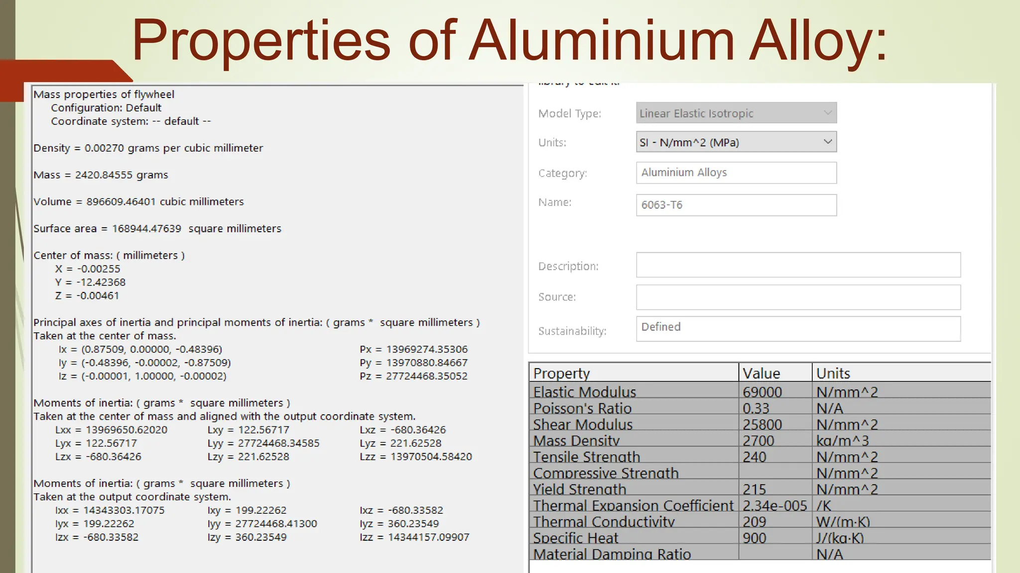
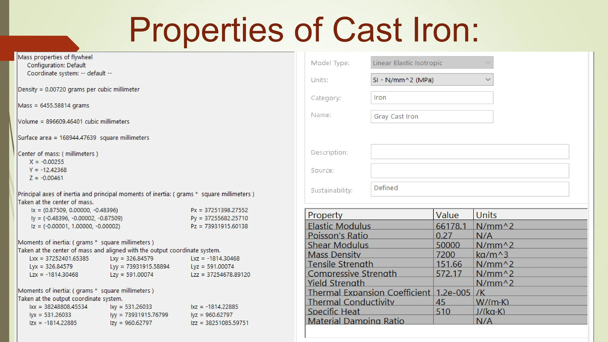
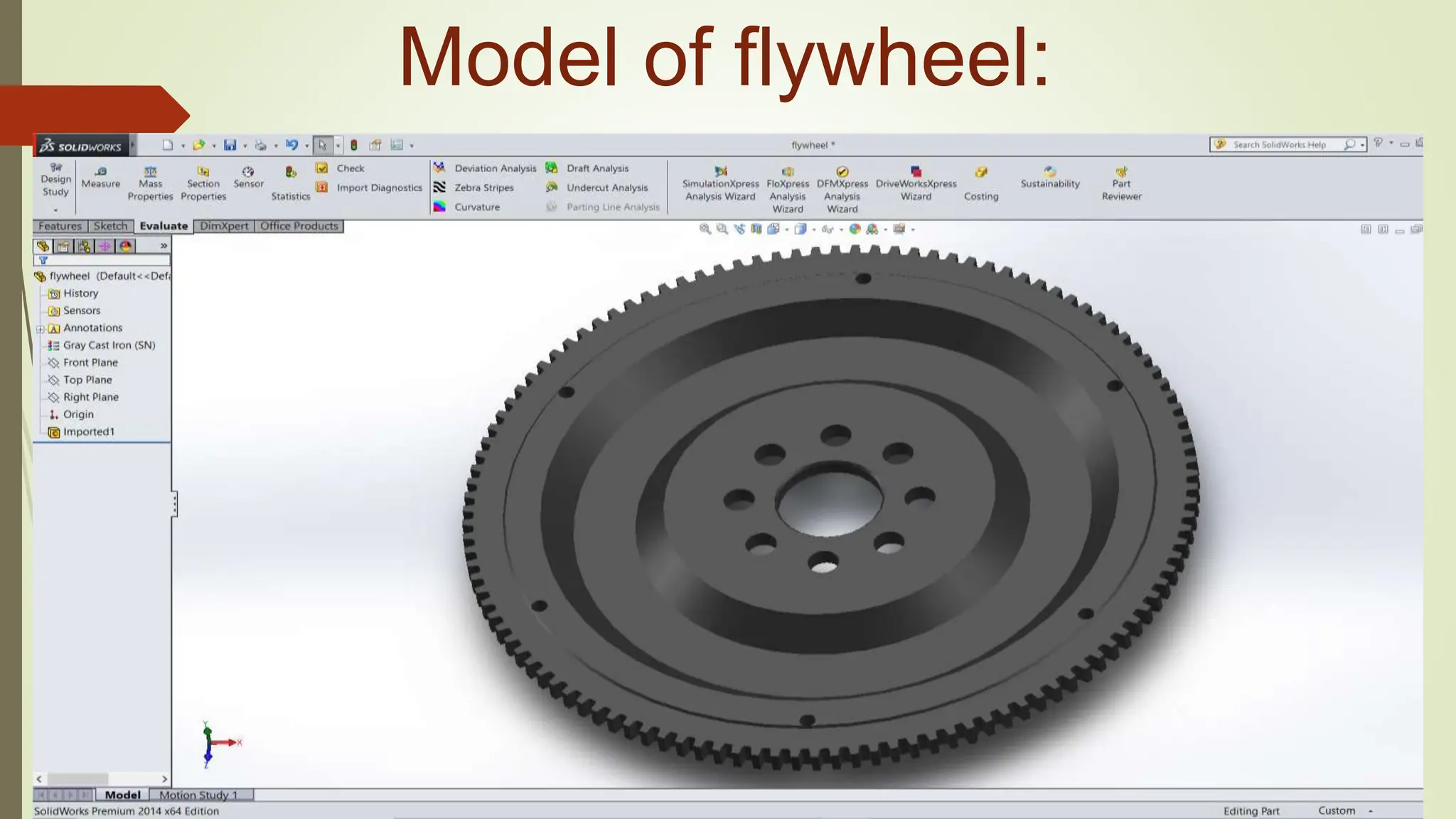
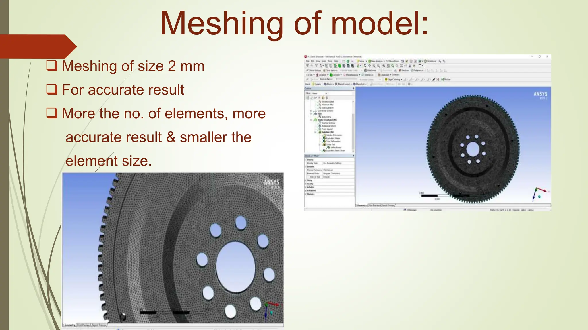
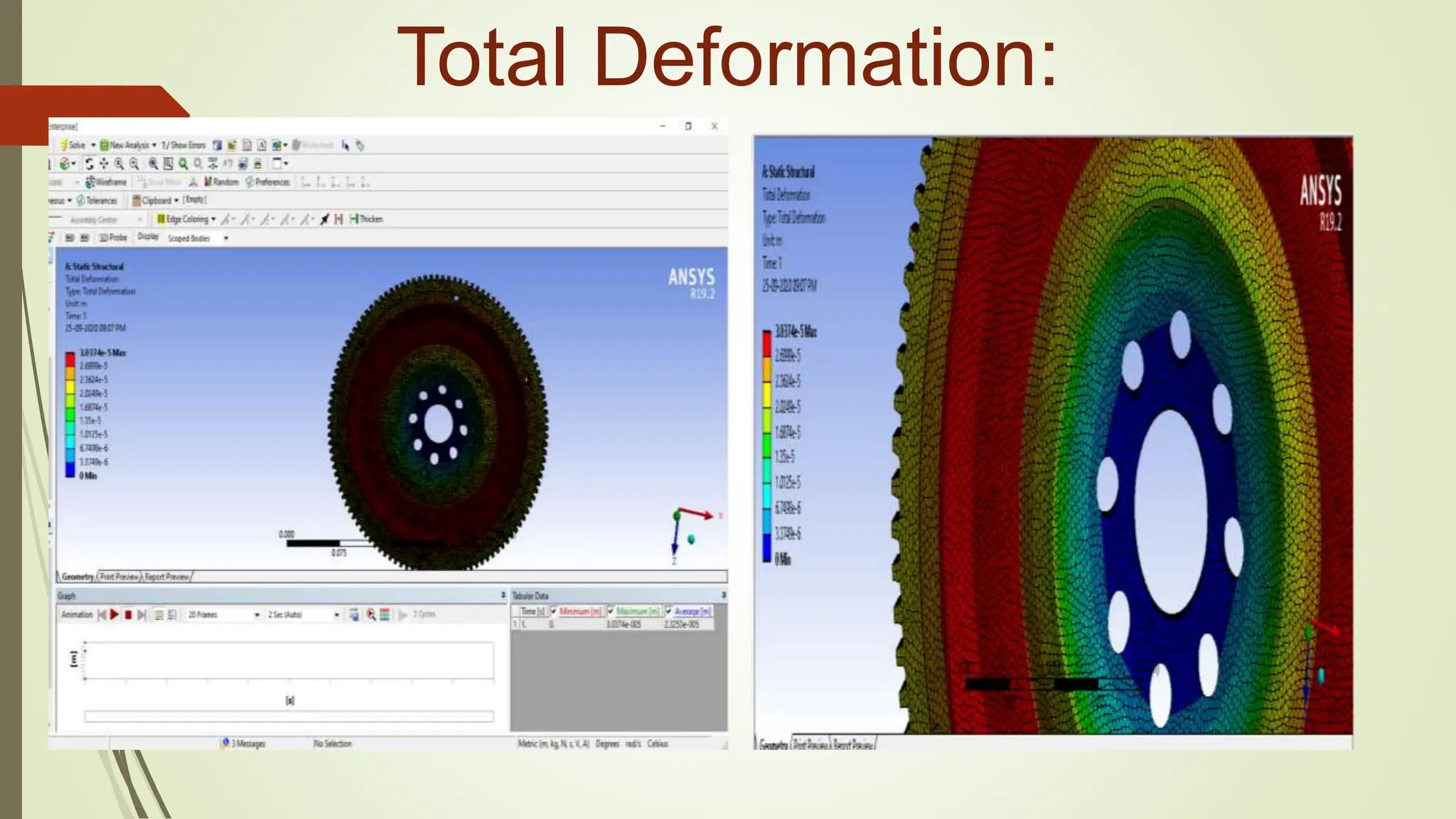
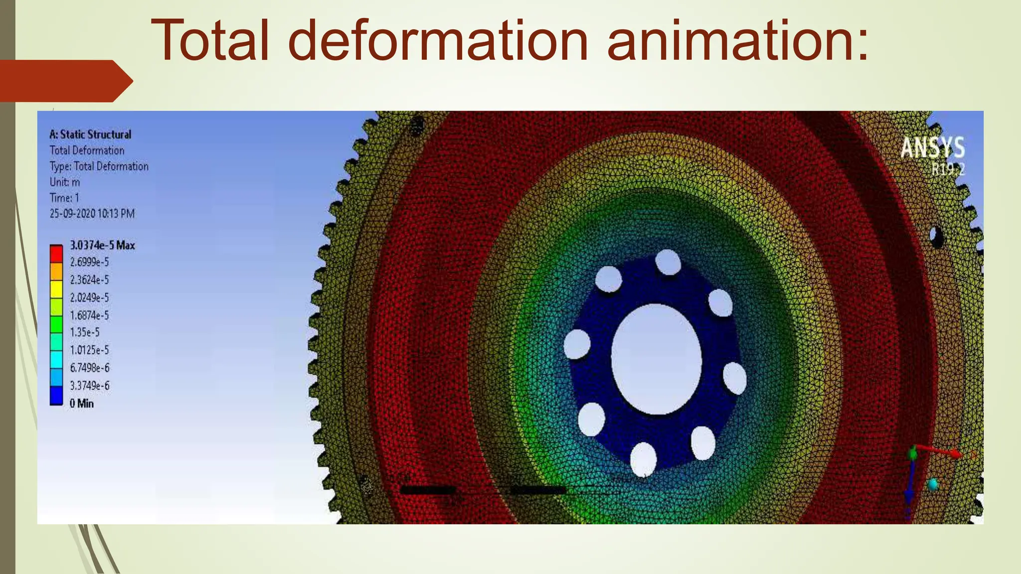
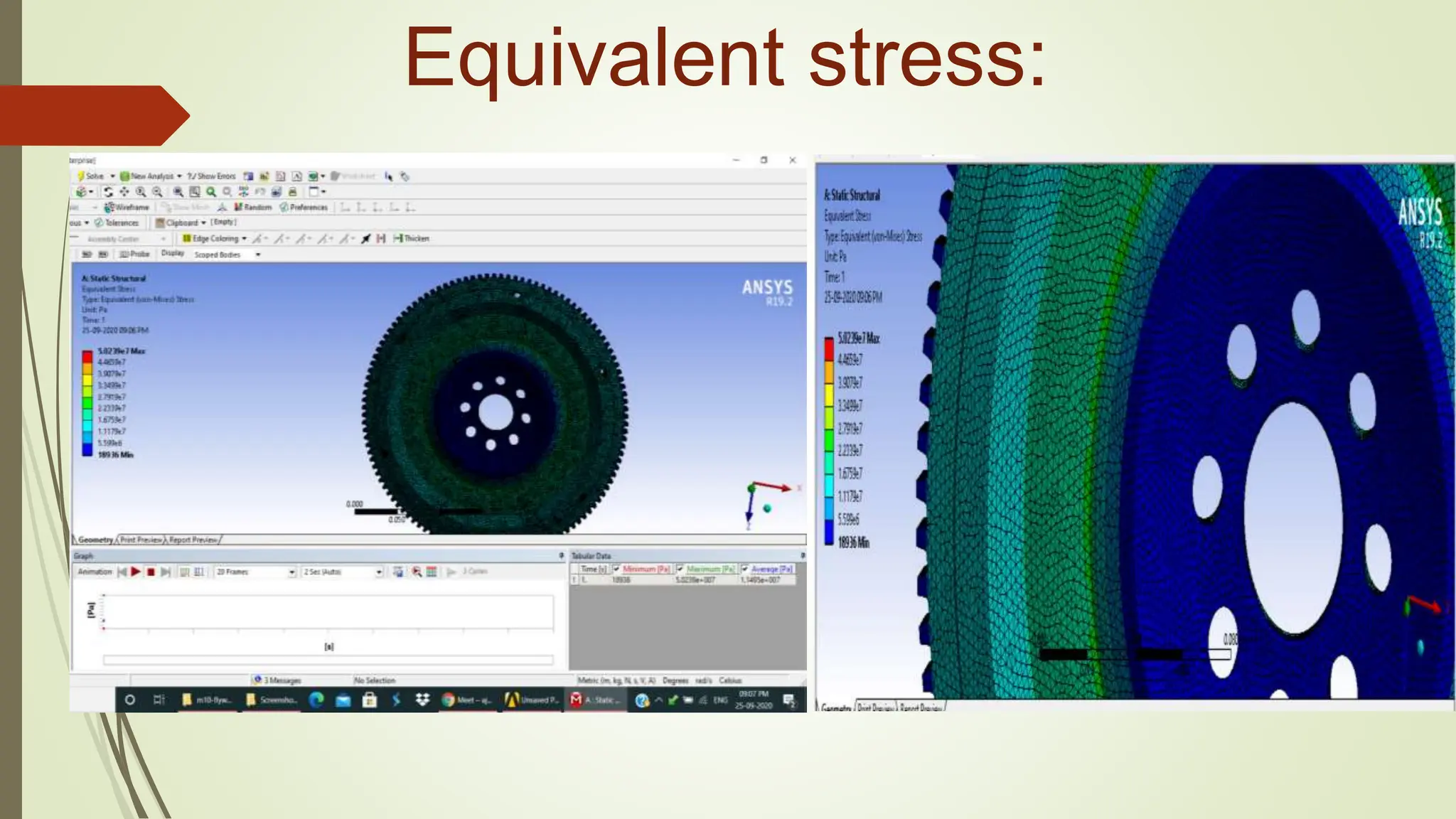
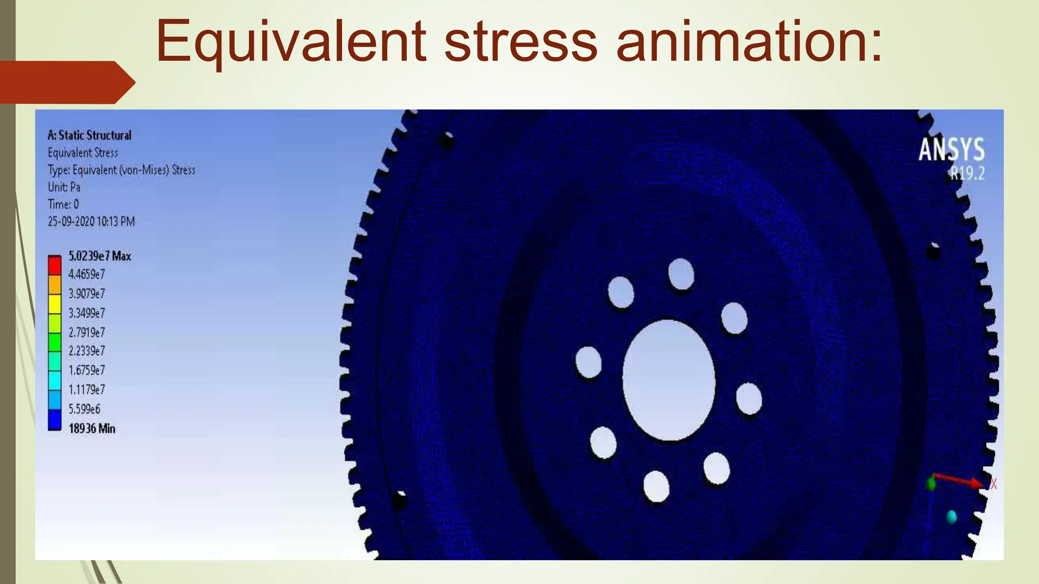
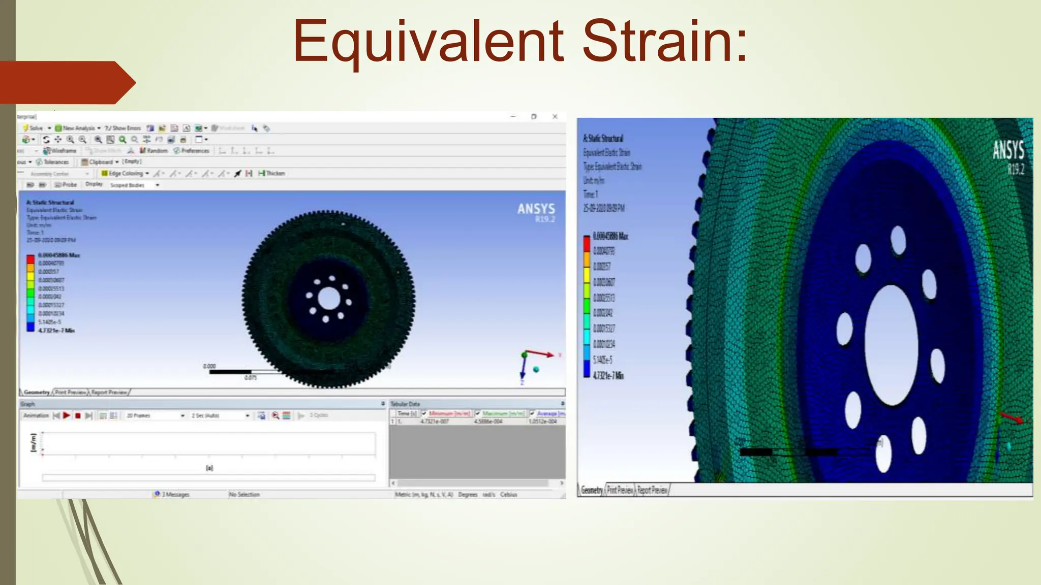
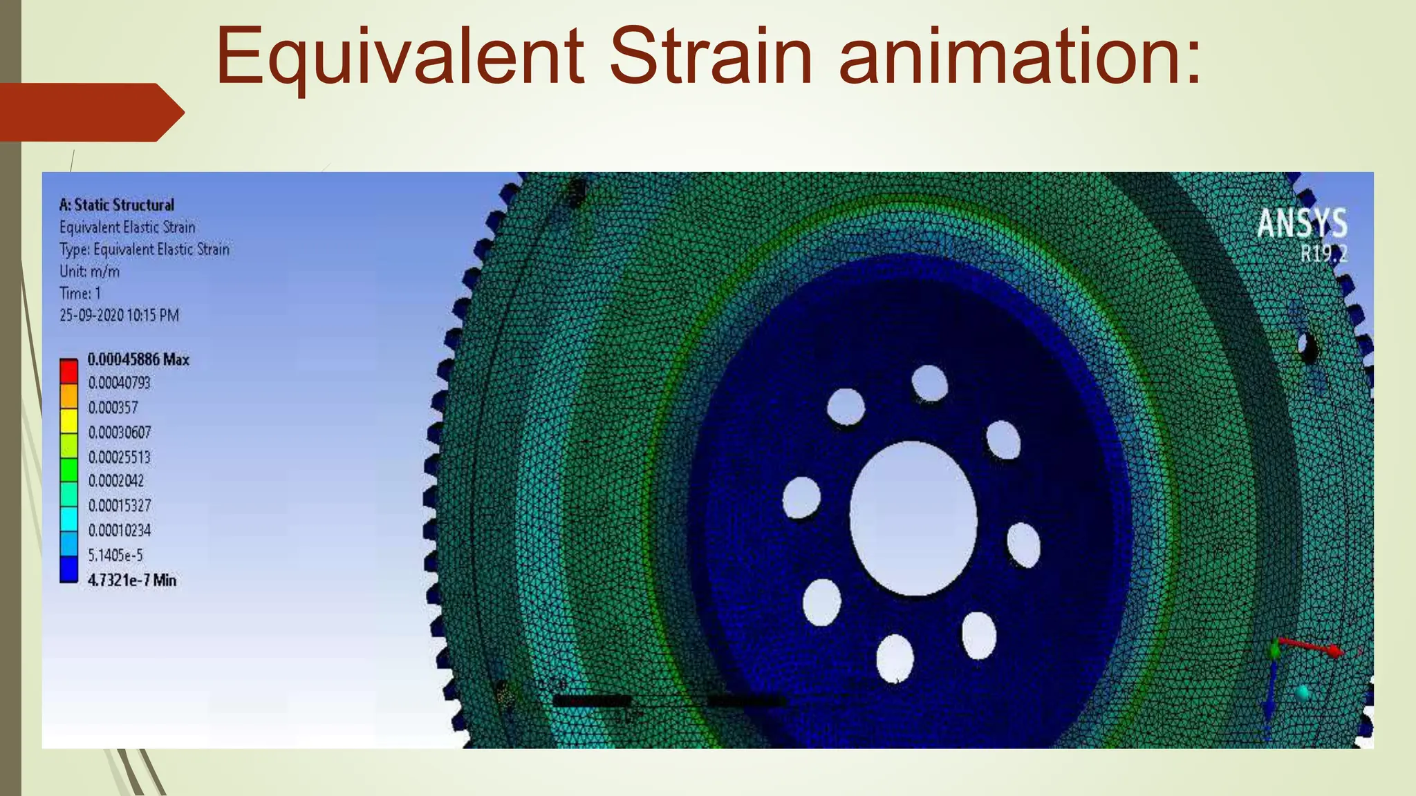
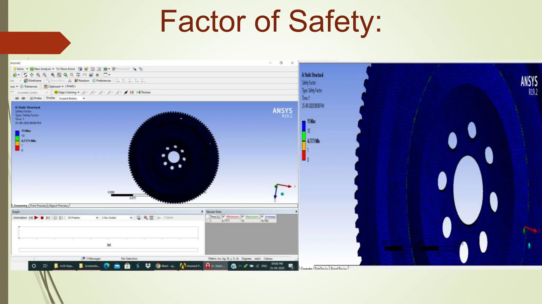
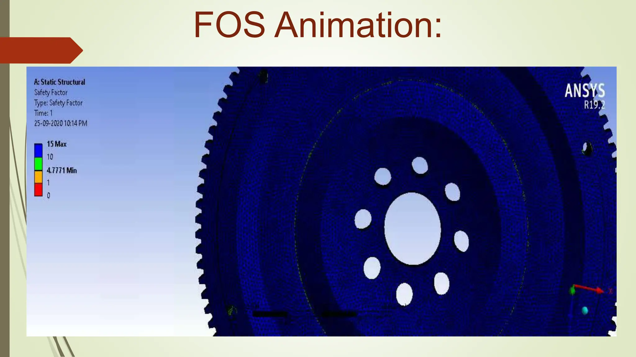
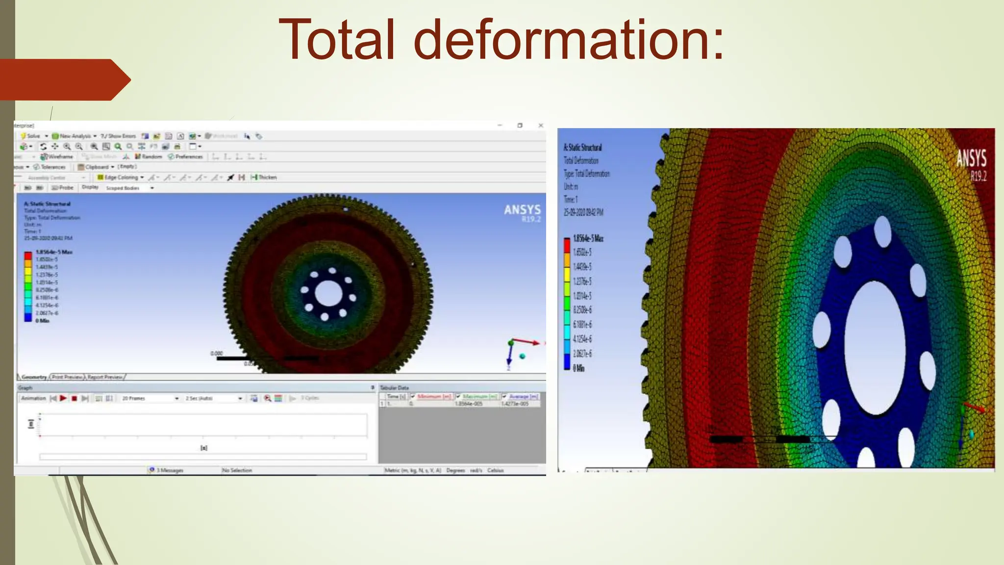
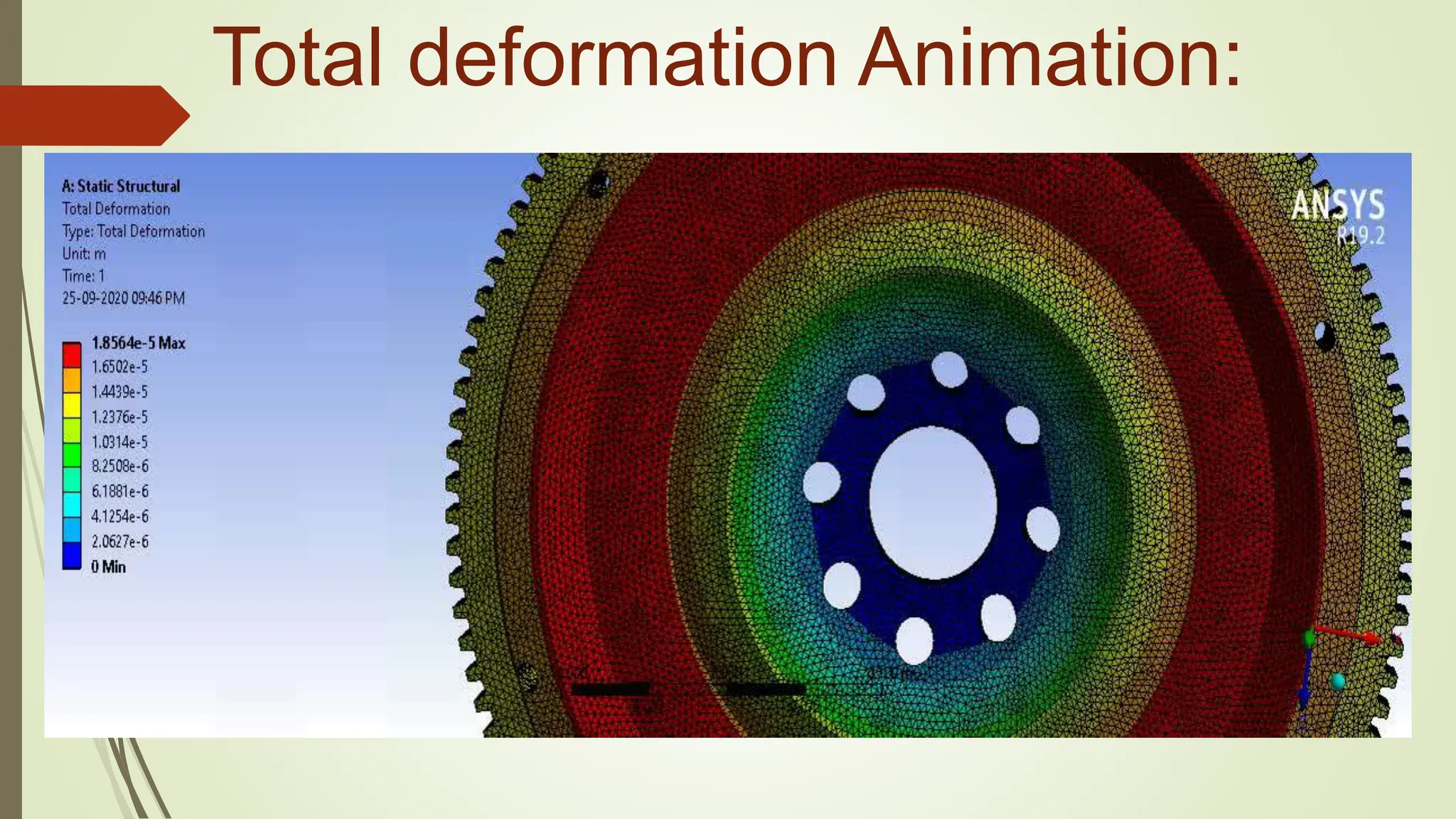
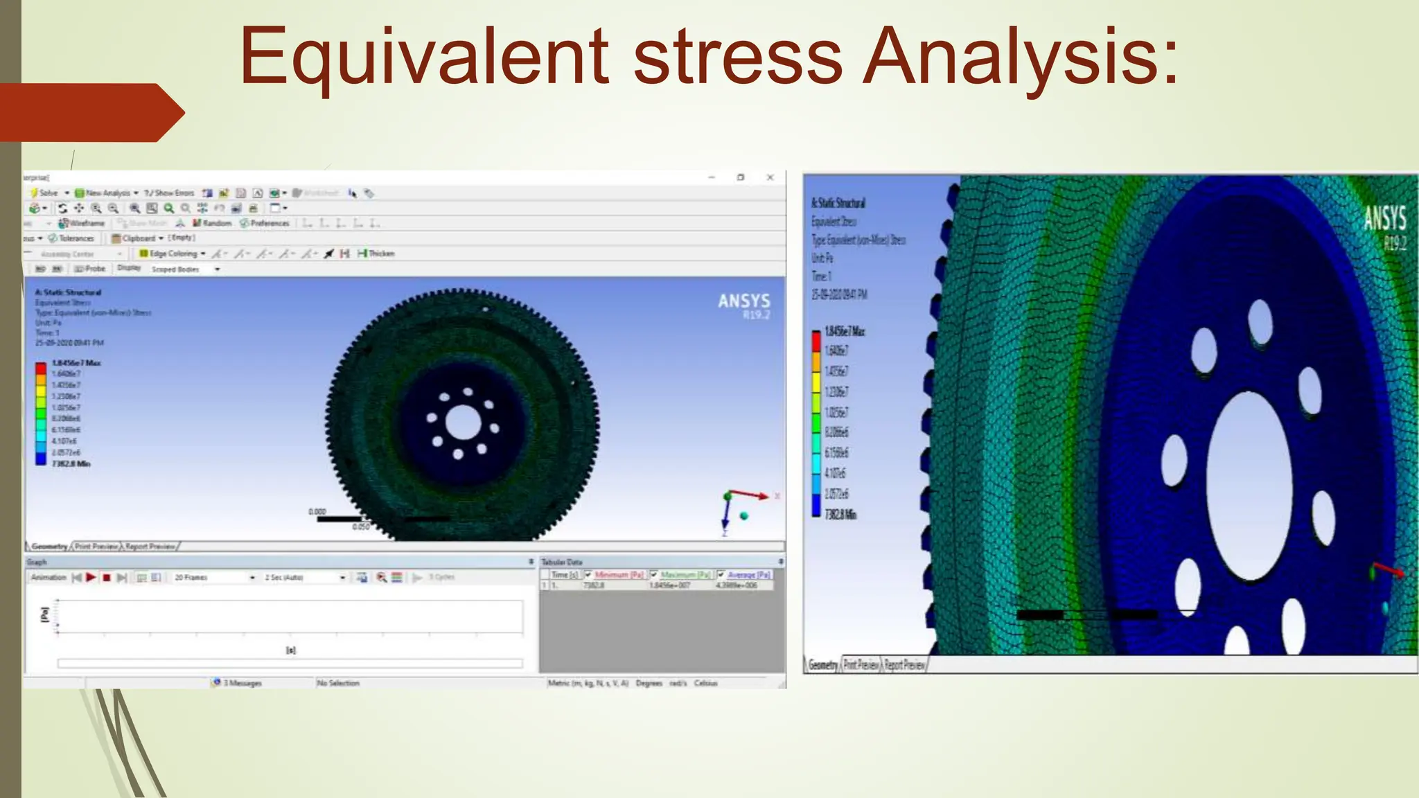
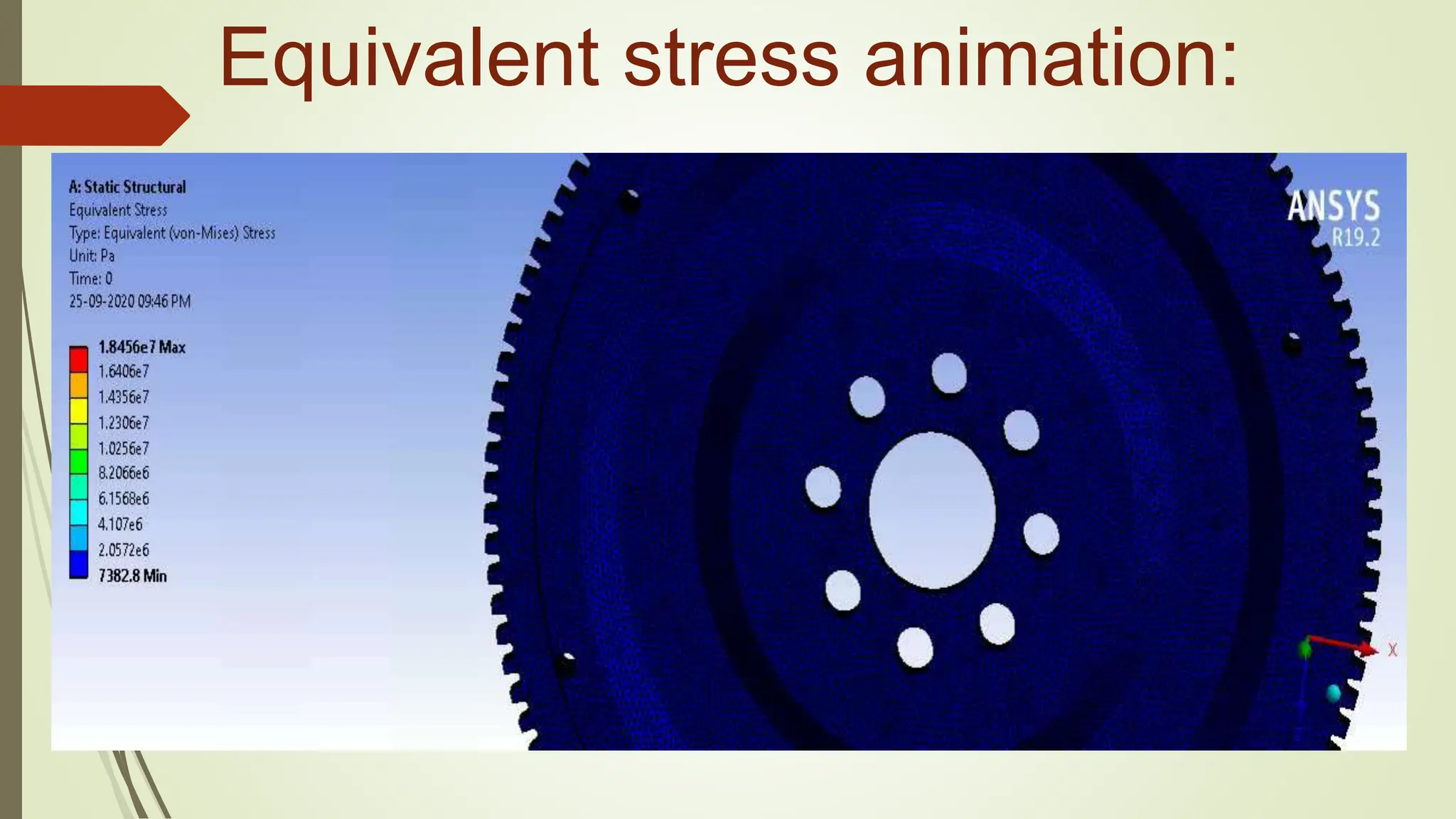
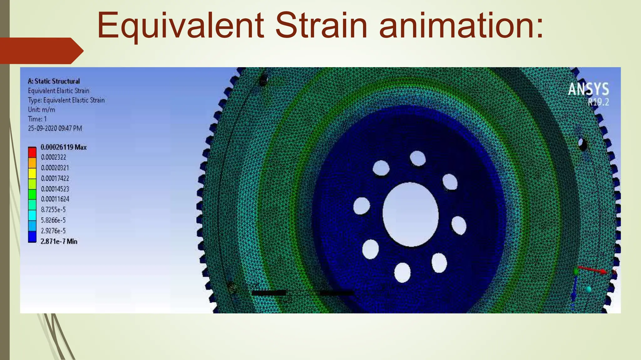
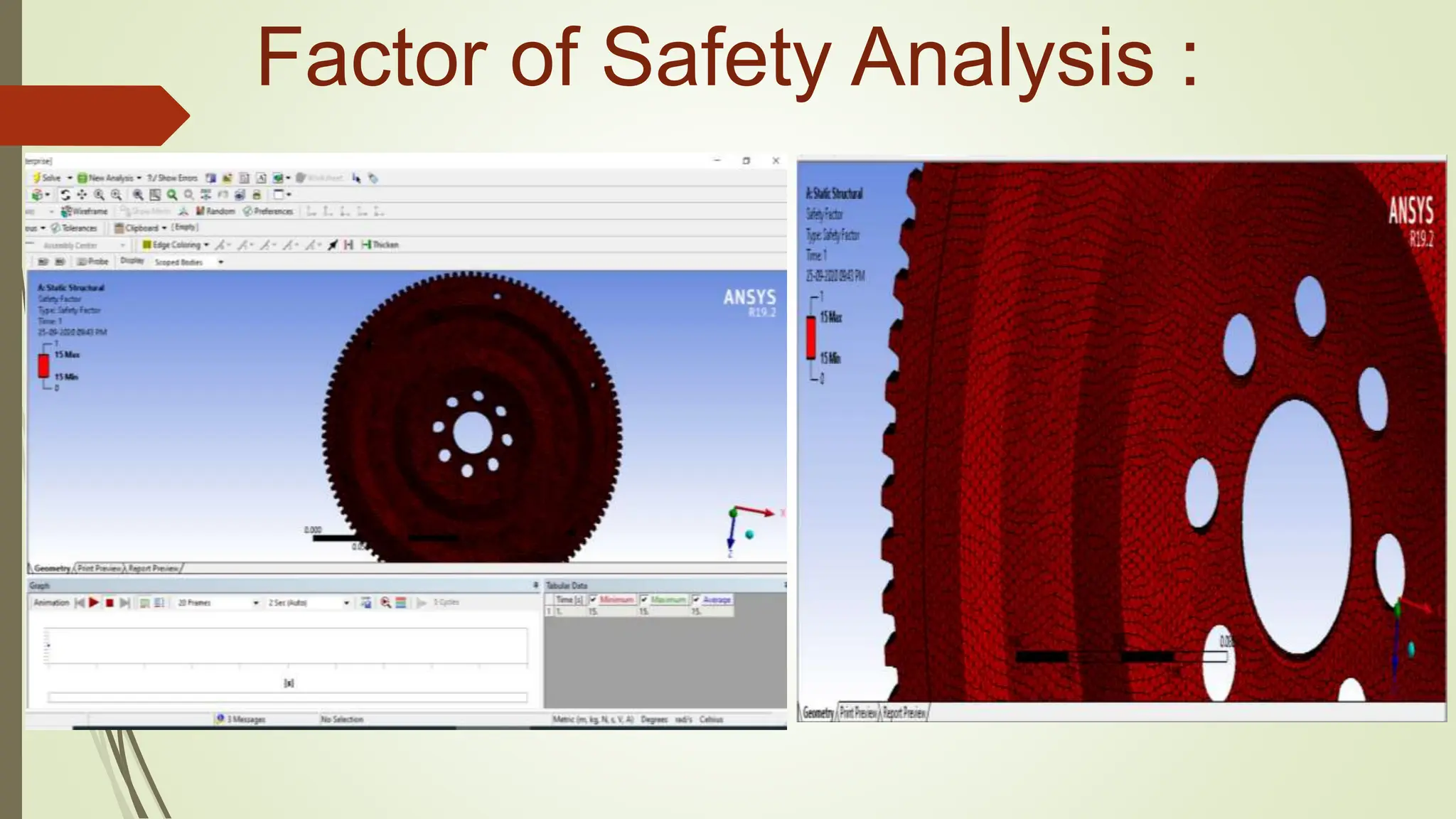
Designing, static and dynamic analysis of a flywheel:
Major Project
By
Aaditi kumari , Pradyumn kumar , Nivas kumar , Ayush kumar
Under the supervision of
Asst. Prof Satyendra kumar mishra
Department of Mechanical Engineering, BCE BHAGALPUR
Outline:
 Introduction
 Functions
 Objective
 Analysis of flywheel of
grey cast iron
 Analysis of flywheel
of Aluminium Alloy
Objective:
1. To find the total deformation.
2. To find the equivalent stress
3. To find equivalent strain
4. To find FOS
Introduction:
Flywheel is a heavy rotating body that acts as a reservoir of energy. Energy is
stored in the form of kinetic energy and is convertible into work without friction.
Reduces the unavoidable fluctuation of speed, arising from fluctuations of
turning moment of the crankshaft.
Flywheel is extensively used in applications like PUNCHING PRESS (power is
supplied at constant rate) & IC ENGINE (power is generated at variable rate)
Functions:
To store and release energy when
needed during the work cycle.
To reduce the power capacity of
electric motor.
To reduce the amplitude of speed
fluctuations.
Need of flywheel:
1. Due to fluctuating load as in punching machines.
2. Due to fluctuating supply as in IC engines.
3. These fluctuations in supply and demand leads to
fluctuations of energy.
4. It results in fluctuations OF speed causing vibrations and
dynamic loading.
Dimension of Flywheel:
Analysis of Flywheel for different
material:
 Aluminium alloy
 Cast iron
We will check the stress distribution and kinetic energy with aluminium
alloy and cast iron.
Because different material have different energy storage capacity.
Properties of Aluminium Alloy:
Properties of Cast Iron:
Model of flywheel:
Meshing of model:
 Meshing of size 2 mm
 For accurate result
 More the no. of elements, more
accurate result & smaller the
element size.
Boundary Conditions:
 A Cylindrical support is given at the shaft and flywheel contact, that is,
the shaft-hole of the flywheel.
 The flywheel is radially and axially made fixed while it is free to rotate
tangentially.
 The flywheel is rotated by 418.67 radians/s with the axis of rotation
being the perpendicular line passing through the centre of the flywheel,
outwards of the plane of flywheel.
 The rotational velocity of 418.67 radians/s is applied in steps of every 1
second linearly.
Boundary conditions:
1. Analysis
of Flywheel of
Grey Cast Iron
Total Deformation:
Total deformation animation:
Equivalent stress:
Equivalent stress animation:
Equivalent Strain:
Equivalent Strain animation:
Factor of Safety:
FOS Animation:
2. Analysis
of Flywheel of
Aluminium Alloy
Total deformation:
Total deformation Animation:
Equivalent stress Analysis:
Equivalent stress animation:
Equivalent Strain Analysis:
Equivalent Strain animation:
Factor of Safety Analysis :
Conclusion:
 The modeling of the flywheel was performed using solidworks. The finite
element analysis (FEA) was carried out using ANSYS workbench for the
two material.
 The anaysis of flywheel of Al Alloy and Gray Cast Iron shows that the
stress developed with Al Alloy is less than that of Gray Cast Iron. Thus, Al
Alloy was found to be the best suited material for constructing the flywheel
due to minimum stress and low weight as compared to cast iron.
final project-1 for mechanical engineering.pptx

final project-1 for mechanical engineering.pptx