Download to read offline


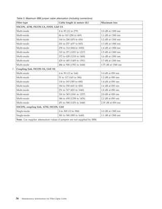
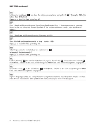
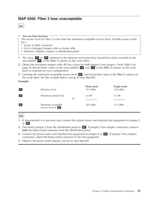
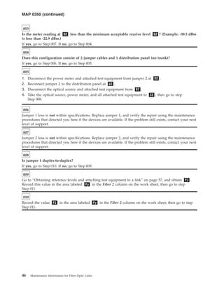
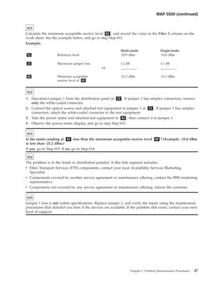


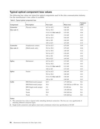

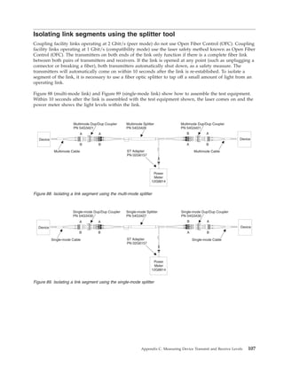

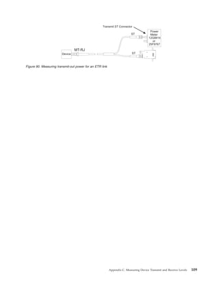


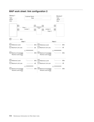
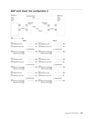
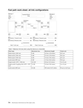
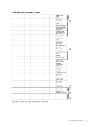
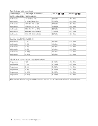
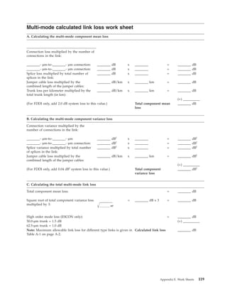
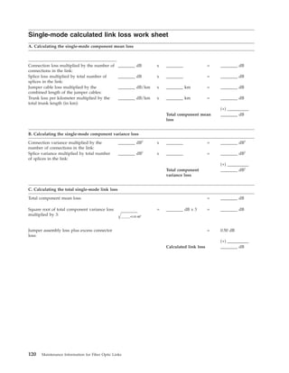
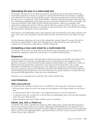
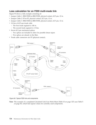
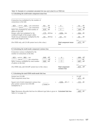

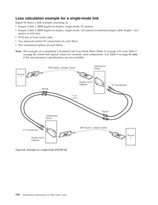
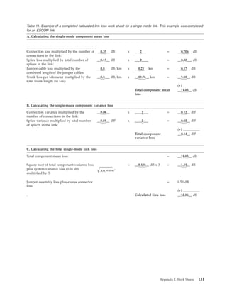


This document provides information about maintaining fiber optic links used in IBM System z processors. It discusses fiber optic cable elements, connectors, jumper cables, trunk cables, distribution panels, couplers, adapters, and test equipment. The document outlines typical link configurations and common failures. It provides procedures for problem determination, installation best practices, documentation guidelines, specifications, and worksheets for link loss calculations.