Downloaded 133 times


![24
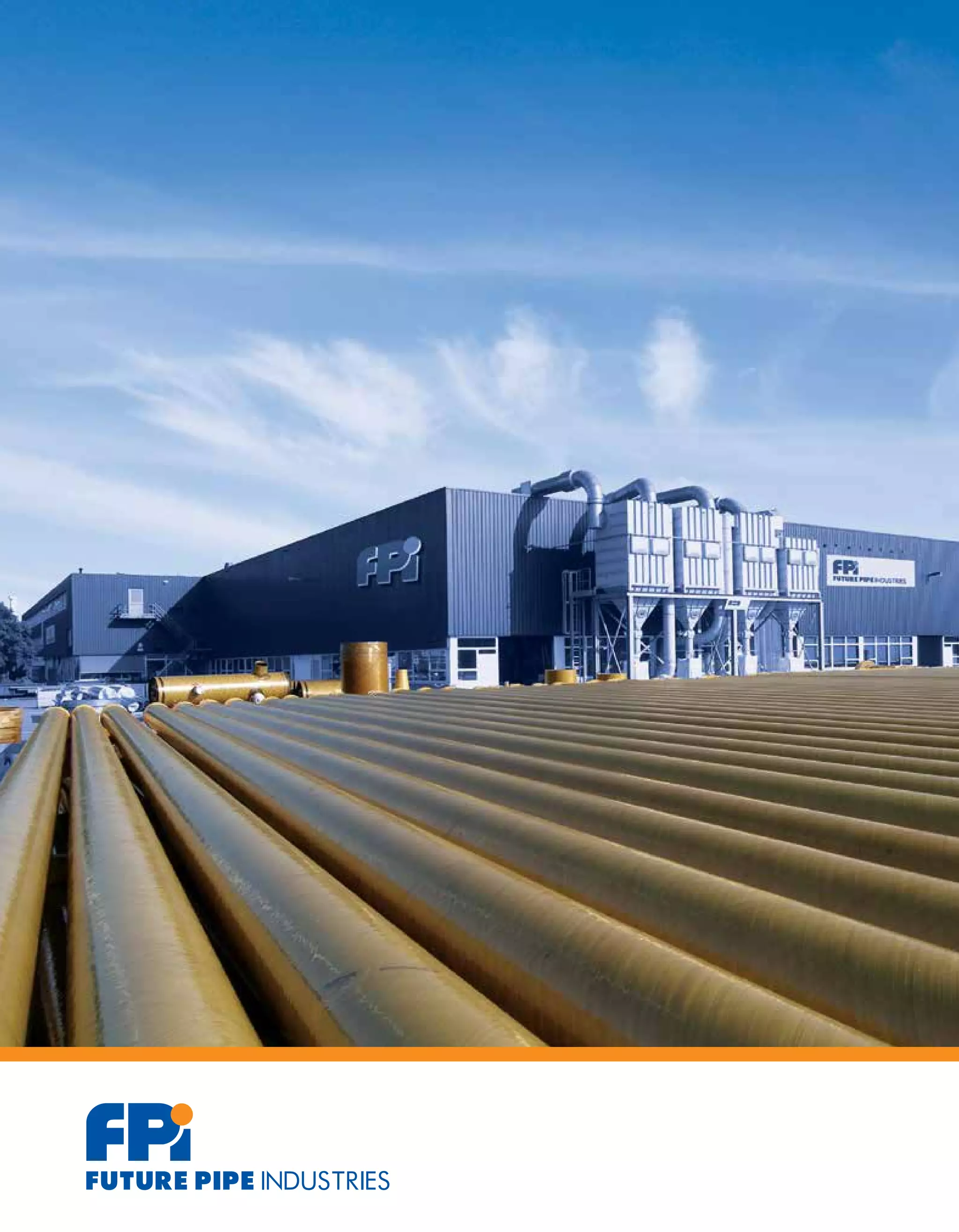
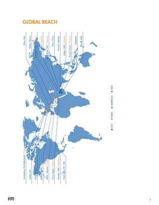
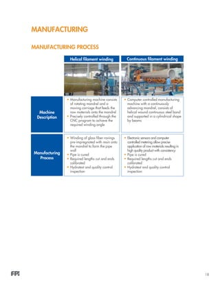
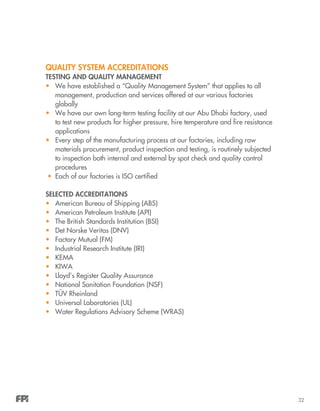
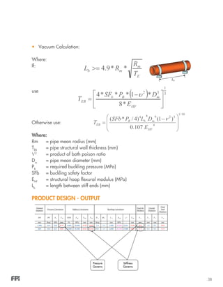
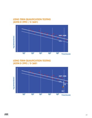
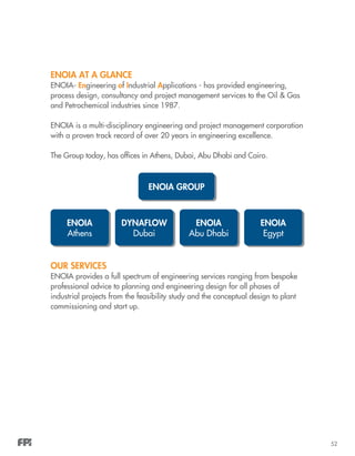
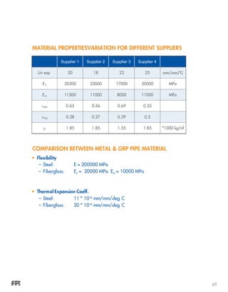
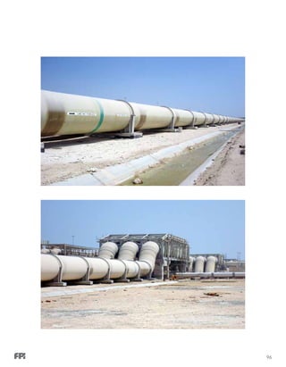
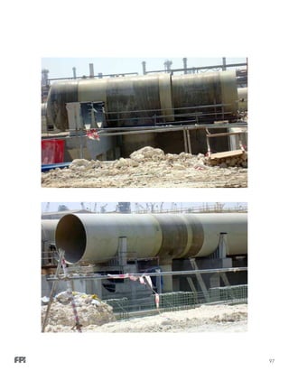
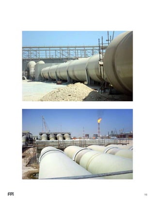
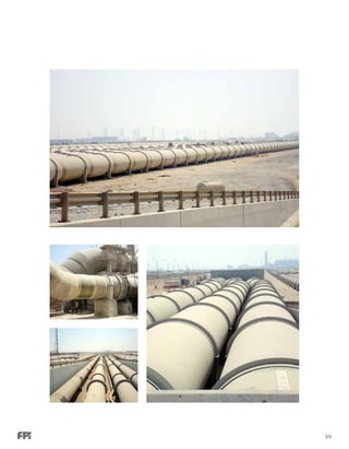
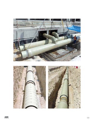
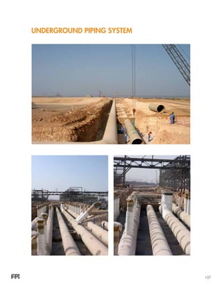
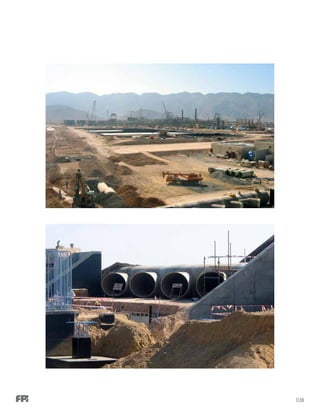
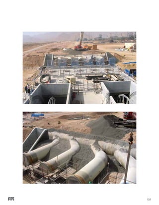
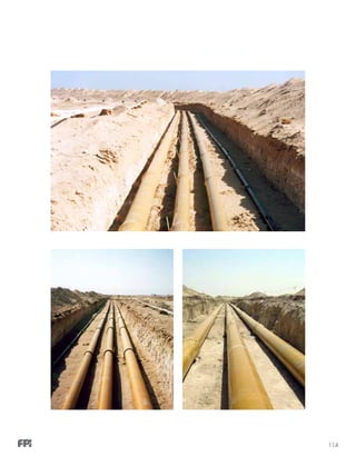
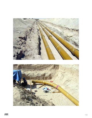
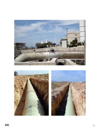
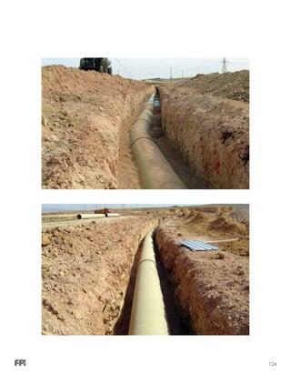
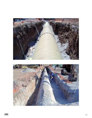
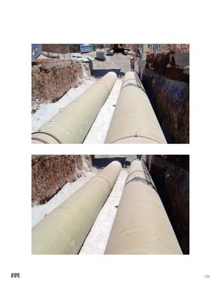
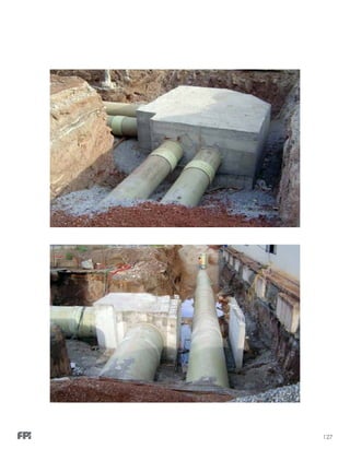
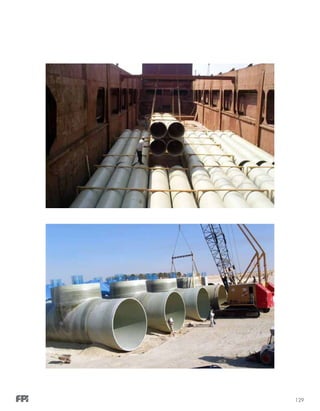
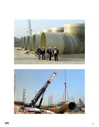
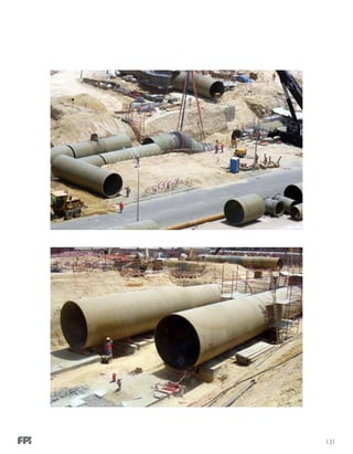
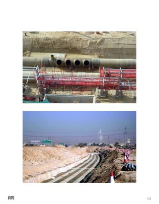
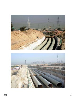
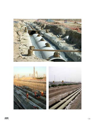
GLASS REINFORCED POLYESTER (GRP): MEDIUM PRESSURE
FIBERSTRONG®
• Isophthalic or Vinylester Resin
• Diameters Range: DN 25 mm [1”] up to DN4000 mm [160”]
• Pressure Range: PN 3 barg [43 psi] up to PN 25 barg [363 psi]
• Jointing System: Double Bell Coupler, Lamination, Flange
• For Underground and Aboveground Installations
• Used In Cooling Water, Industrial Waste Water, Fire Water, Seawater Lines,
Sewerage & Drainage as well as Chlorination Lines.
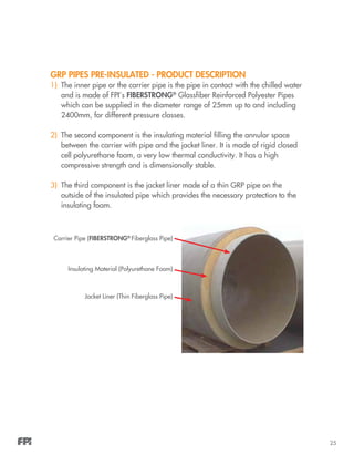
PRE-INSULATED GRP PIPE FOR CHILLED WATER SYSTEMS
Fiberglass (GRP) Pre-Insulated Product Description.
Today, GRP (Glass Reinforced Plastics) non-corrosive piping materials have
become a well established replacement to steel in water, oil & gas and
industrial/petrochemical applications. This is mainly because of its non-
corrosive nature and reliability due to advances in manufacturing processes,
high quality raw materials and well established design, testing, and installation
standards.](https://image.slidesharecdn.com/fiberglassbook-150624032858-lva1-app6892/85/Fiberglassbook-28-320.jpg)

![27
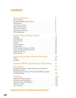
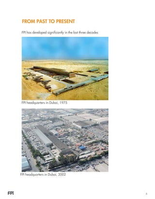
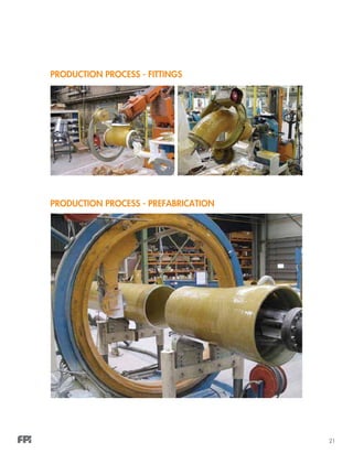
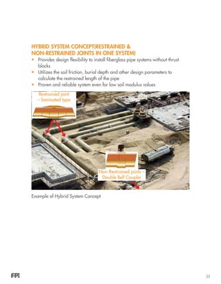
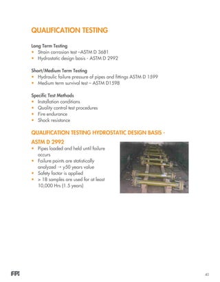
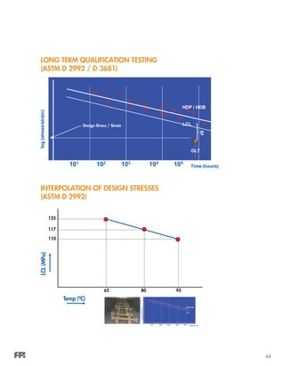
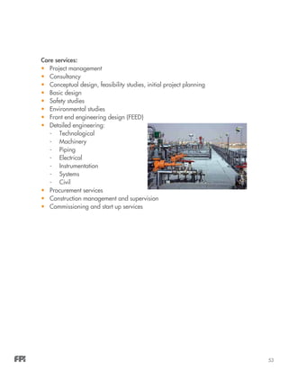
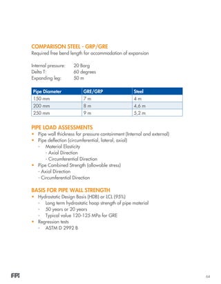
GLASS REINFORCED EPOXY (GRE): MEDIUM PRESSURE
WAVISTRONG®
• Epoxy resin
• Diameters range : DN 25 mm [1”] up to DN1600mm [64”]
• Pressure range : PN 8 barg [116 psi] up to PN 50 barg [725 psi]
• For above and underground installations
• Jointing System : Adhesive Bonded Joint, Lamination, Rubber Seal Lock Joint,
Flange
• Used as utilities piping (e.g. fire fighting systems and oil & gas,
petrochemical & industrial applications & offshore applications
WAVISTRONG®
H2
O
A new system introduced for potable water applications
• The pipe, fitting and joint are GRE corrosion resistant pipe systems intended
for underground use
• Can be made available up to DN 4000 if needed and up to 25 barg
• It consists of a thermosetting chemical resistant epoxy resin and fiberglass
reinforcements
Advantages:
• Designed for a 50 year lifetime
• Lightweight
• Uses a variety of jointing systems
• Corrosion resistant
• UV resistant](https://image.slidesharecdn.com/fiberglassbook-150624032858-lva1-app6892/85/Fiberglassbook-31-320.jpg)
![28
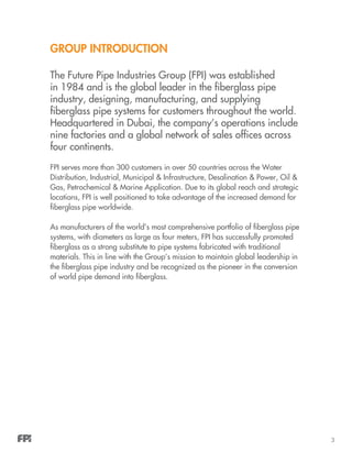
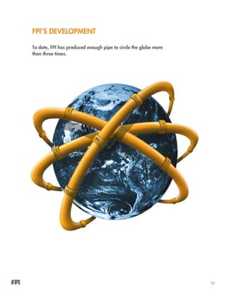
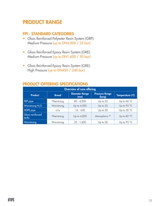
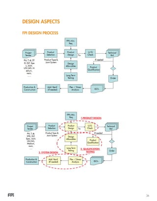
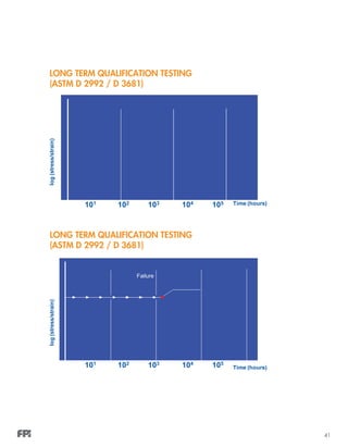
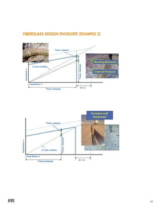
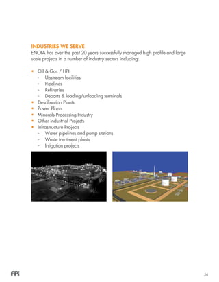
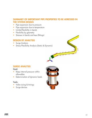
GLASS REINFORCED EPOXY (GRE): HIGH PRESSURE
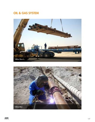
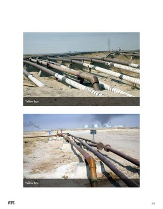
YELLOW BOX®
• Epoxy Resin
• Diameters range : DN 50 mm [2”] up to DN 450 mm [18”]
• Pressure range : PN 35 barg [500 psi] up to PN 240 barg [3500 psi]
• For above and underground Installations
• Jointing System : API Threaded Joint , Flange
• Used for oil & gas flow lines, gathering systems & injection systems
NEW DEVELOPMENT
Large Diameter Glass Reinforced Epoxy (GRE)
WAVISTRONG®
• Epoxy Resin
• Diameters range: up to DN4,000 mm
• Pressure range: PN 6 barg up to PN 25 barg
• Jointing System: Double Bell Coupler, Butt & Wrap, Flange
• For underground and aboveground installations
• Used in cooling water, industrial waste water, fire water, oily water,
sewerage and drainage lines](https://image.slidesharecdn.com/fiberglassbook-150624032858-lva1-app6892/85/Fiberglassbook-32-320.jpg)


![46
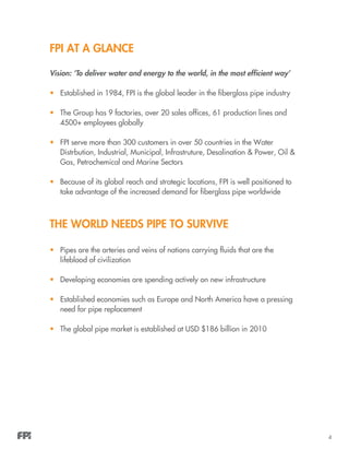
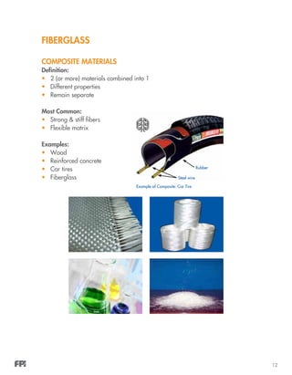
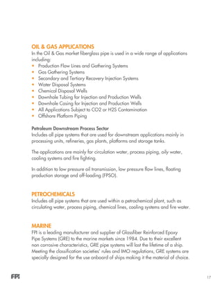
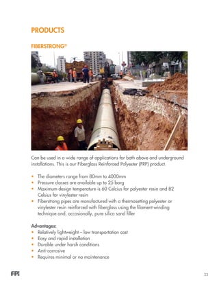
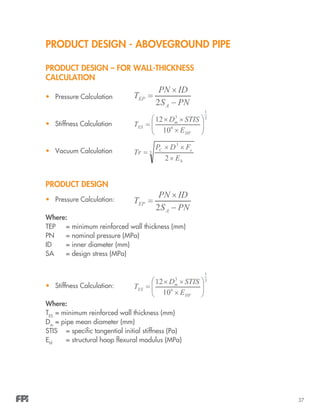
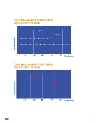
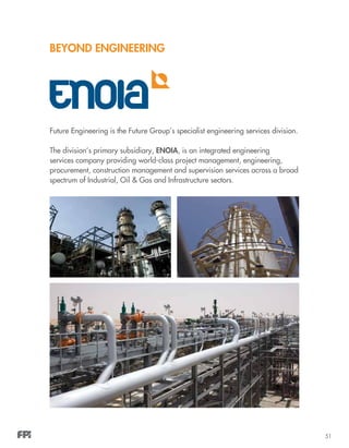
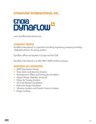
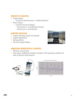
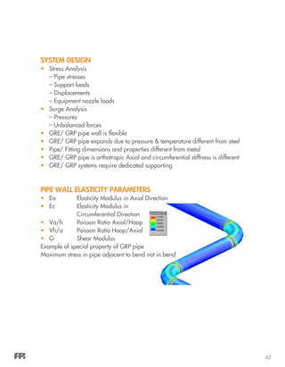
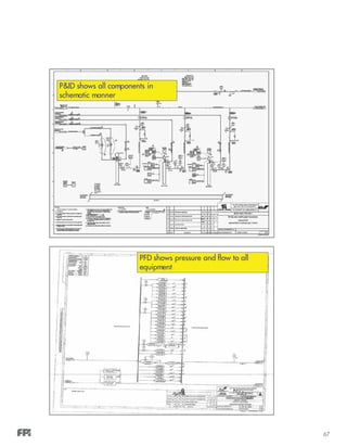
SYSTEM DESIGN
DESIGN ENVELOPE; STEEL VERSUS FIBERGLASS
FIBERGLASS DESIGN ENVELOPE (Construction)
AxialStress,σA,[MPa]
Hoop Stress, σH [MPa]
1:1 load condition
Steel Pipe
Fiberglass Pipe
2:1 load condition
(pipe under internal pressure)
no reservation for
axial stresses due to
bending, thermal
expansion, etc
large reservation for
axial stresses due to
bending, thermal
expansion, etc](https://image.slidesharecdn.com/fiberglassbook-150624032858-lva1-app6892/85/Fiberglassbook-50-320.jpg)


![57
DYNAFLOW CLIENTS
End users, EPC contractors, and consultants working in the following sectors:
• Petrochemical
• Chemical
• Oil & Gas treatment and production (onshore offshore)
• Water treatment
• Pipelines
• Municipal
• MEP contractors
DYNAFLOW EXPERTISE IN FIBERGLASS
• DFI possesses special expertise in the design of Large Bore fiberglass piping
systems (Epoxy /Polyester / Vinylester)
• DFI plays an active role in the introduction and further development of (new)
standards for fiberglass applications
(ISO-14692)
CURRENT STATE OF THE ART GRP EXPERIENCE
0
10
20
30
40
50
60
70
80
90
100
0 250 500 750 1000 1250 1500 1750 2000 2250 2500 2750 3000 3250 3500 3750 4000
Nominal Diameter [mm]
DesignPressure[Barg].
Pipe wallload P*D=2700
N/mm
Series3](https://image.slidesharecdn.com/fiberglassbook-150624032858-lva1-app6892/85/Fiberglassbook-61-320.jpg)


This document provides an overview of Future Pipe Industries (FPI) and their fiberglass pipe product range and design aspects. It discusses FPI's history and growth over time, their global manufacturing presence, the industries they serve, and the advantages of fiberglass pipes. It also provides details on FPI's main fiberglass pipe product lines - Fiberstrong pipes for medium pressure and Wavistrong pipes for medium and high pressure applications. The document describes the manufacturing and design of fiberglass pipes and fittings.


