Fiber Bragg Grating Based Sensors And Systems Oleg Morozov
Fiber Bragg Grating Based Sensors And Systems Oleg Morozov
Fiber Bragg Grating Based Sensors And Systems Oleg Morozov
Fiber Bragg Grating Based Sensors And Systems Oleg Morozov
Fiber Bragg Grating Based Sensors And Systems Oleg Morozov
1.
Fiber Bragg GratingBased Sensors And Systems
Oleg Morozov download
https://ebookbell.com/product/fiber-bragg-grating-based-sensors-
and-systems-oleg-morozov-50655490
Explore and download more ebooks at ebookbell.com
2.
Here are somerecommended products that we believe you will be
interested in. You can click the link to download.
Fiber Bragg Grating Sensors Development And Applications 1st Edition
Hisham K Hisham
https://ebookbell.com/product/fiber-bragg-grating-sensors-development-
and-applications-1st-edition-hisham-k-hisham-12056408
Fiber Bragg Gratings Second Edition Optics And Photonics Series 2nd
Edition Raman Kashyap
https://ebookbell.com/product/fiber-bragg-gratings-second-edition-
optics-and-photonics-series-2nd-edition-raman-kashyap-2107408
Fibre Bragg Grating And Nocore Fibre Sensors 1st Ed Suzairi Daud
https://ebookbell.com/product/fibre-bragg-grating-and-nocore-fibre-
sensors-1st-ed-suzairi-daud-7150926
Polymer Optical Fiber Bragg Gratingsfabrication And Sensing
Applications 1st Edition Ricardo Oliveira
https://ebookbell.com/product/polymer-optical-fiber-bragg-
gratingsfabrication-and-sensing-applications-1st-edition-ricardo-
oliveira-11910766
3.
Fibre Bragg GratingsIn Harsh And Space Environments Principles And
Applications Brahim Assa
https://ebookbell.com/product/fibre-bragg-gratings-in-harsh-and-space-
environments-principles-and-applications-brahim-assa-48779126
Roots Radicals And Rockers How Skiffle Changed The World Bragg
https://ebookbell.com/product/roots-radicals-and-rockers-how-skiffle-
changed-the-world-bragg-11834676
Fiberopticbased Sensing Systems Lazo M Manojlovi
https://ebookbell.com/product/fiberopticbased-sensing-systems-lazo-m-
manojlovi-46192382
Fiberreinforced Composites Materials Manufacturing And Design Th 3rd
Edition Mallick Pk Staff
https://ebookbell.com/product/fiberreinforced-composites-materials-
manufacturing-and-design-th-3rd-edition-mallick-pk-staff-47239556
Fiber Reinforced Polymeric Materials And Sustainable Structures
Shamsher Bahadur Singh
https://ebookbell.com/product/fiber-reinforced-polymeric-materials-
and-sustainable-structures-shamsher-bahadur-singh-48004078
5.
Fiber Bragg
Grating Based
Sensors
andSystems
Printed Edition of the Special Issue Published in Sensors
www.mdpi.com/journal/sensors
Oleg Morozov
Edited by
Contents
About the Editor. . . . . . . . . . . . . . . . . . . . . . . . . . . . . . . . . . . . . . . . . . . . . . vii
Preface to ”Fiber Bragg Grating Based Sensors and Systems” . . . . . . . . . . . . . . . . . . . . ix
Florian Heilmeier, Robert Koos, Michael Singer, Constantin Bauer, Peter Hornberger, Jochen
Hiller and Wolfram Volk
Evaluation of Strain Transition Properties between Cast-In Fibre Bragg Gratings and Cast
Aluminium during Uniaxial Straining
Reprinted from: Sensors 2020, 20, 6276, doi:10.3390/s20216276 . . . . . . . . . . . . . . . . . . . . 1
Demetrio Cristiani, Luca Colombo, Wojciech Zielinski, Claudio Sbarufatti, Francesco
Cadini, Michal Dziendzikowski and Marco Giglio
On the Evaluation of a Coupled Sequential Approach for Rotorcraft Landing Simulation
Reprinted from: Sensors 2020, 20, 2540, doi:10.3390/s20092540 . . . . . . . . . . . . . . . . . . . . 21
Steve Gilbertson, Mark Pickrell, Dario Castano, Gary Salazar, Tom Beery, Samuel Stone and
Joshem Gibson
High Speed, Localized Multi-Point Strain Measurements on a Containment Vessel at 1.7 MHz
Using Swept-Wavelength Laser-Interrogated Fiber Bragg Gratings
Reprinted from: Sensors 2020, 20, 5935, doi:10.3390/s20205935 . . . . . . . . . . . . . . . . . . . . 45
Jie Wei, Yanpeng Hao, Yuan Fu, Lin Yang, Jiulin Gan and Han Li
Experimental Study on Glaze Icing Detection of 110 kV Composite Insulators Using Fiber Bragg
Gratings
Reprinted from: Sensors 2020, 20, 1834, doi:10.3390/s20071834 . . . . . . . . . . . . . . . . . . . . 73
Jun Sik Kim, Byung Kook Kim, Minsu Jang, Kyumin Kang, Dae Eun Kim, Byeong-Kwon Ju
and Jinseok Kim
Wearable Hand Module and Real-Time Tracking Algorithms for Measuring Finger Joint Angles
of Different Hand Sizes with High Accuracy Using FBG Strain Sensor
Reprinted from: Sensors 2020, 20, 1921, doi:10.3390/s20071921 . . . . . . . . . . . . . . . . . . . . 87
Shi-Zhi Chen, De-Cheng Feng and Wan-Shui Han
Comparative Study of Damage Detection Methods Based on Long-Gauge FBG for Highway
Bridges
Reprinted from: Sensors 2020, 20, 3623, doi:10.3390/s20133623 . . . . . . . . . . . . . . . . . . . . 107
Oleg Morozov, Airat Sakhabutdinov, Vladimir Anfinogentov, Rinat Misbakhov, Artem
Kuznetsov and Timur Agliullin
Multi-Addressed Fiber Bragg Structures for Microwave-Photonic Sensor Systems
Reprinted from: Sensors 2020, 20, 2693, doi:10.3390/s20092693 . . . . . . . . . . . . . . . . . . . . 131
Timur Agliullin, Robert Gubaidullin, Airat Sakhabutdinov, Oleg Morozov, Artem
Kuznetsov and Valentin Ivanov
Addressed Fiber Bragg Structures in Load-Sensing Wheel Hub Bearings
Reprinted from: Sensors 2020, 20, 6191, doi:10.3390/s20216191 . . . . . . . . . . . . . . . . . . . . 141
Azat Gizatulin, Ivan Meshkov, Irina Vinogradova, Valery Bagmanov, Elizaveta Grakhova
and Albert Sultanov
Generation of Vortex Optical Beams Based on Chiral Fiber-Optic Periodic Structures
Reprinted from: Sensors 2020, 20, 5345, doi:10.3390/s20185345 . . . . . . . . . . . . . . . . . . . . 155
v
11.
Eduard Muslimov, NadezhdaPavlycheva, Emmanuel Hugot, Simona Lombardo, Ilnur
Nureev and Oleg Morozov
Optical Designs with Curved Detectors for Fiber Bragg Grating Interrogation Monitors
Reprinted from: Sensors 2020, 21, 34, doi:10.3390/s21010034 . . . . . . . . . . . . . . . . . . . . . . 171
Joao B. Rosolem, Marcio C. Argentato, Fábio R. Bassan, Rivael S. Penze, Claudio Floridia,
Artur de A. Silva, Deleon Vasconcelos and Marcelo A. Ramos Junior
Demonstration of a Filterless, Multi-Point, and Temperature-Independent Fiber Bragg Grating
Dynamical Demodulator Using Pulse-Width Modulation
Reprinted from: Sensors 2020, 20, 5825, doi:10.3390/s20205825 . . . . . . . . . . . . . . . . . . . . 185
François Ouellette, Zhonghua Ou and Jianfeng Li
Dual Wavelength Differential Detection of Fiber Bragg Grating Sensors with a Pulsed DFB Laser
Reprinted from: Sensors 2020, 20, 4766, doi:10.3390/s20174766 . . . . . . . . . . . . . . . . . . . . 201
vi
12.
About the Editor
OlegMorozov
Oleg G. Morozov (D. of Tech. Sc.) is a Full Professor and the Head of the RadioPhotonics and
Microwave Technologies Department of the Institute of RadioElectronics, Photonics and Digital
Technologies of the Kazan National Research Technical University - KAI (KNRTU-KAI) n.a. A.N.
Tupolev, Russia. He is also the Director of the R&D Institute in Applied Electrodynamics, Photonics
and Living Systems of the KNRTU-KAI. Since 2001 he is a member of Russian Federal Register of
Experts in Science and Technology, since 2017 he is a member of the expert council in Electronics,
Photonics, Instrumentation And Communications of the Supreme Attestation Commission of Russia.
Over the past five years he has been awarded the title of Senior member of SPIE, OSA and IEEE. His
main research interests include microwave photonics; fiber-optic sensors and inerrogation systems;
infocommunication systems of optical, microwave and terahertz ranges.
vii
14.
Preface to ”FiberBragg Grating Based Sensors and
Systems”
Today, no one doubts that fiber Bragg gratings (FBGs) have become the most used tool
for measuring various physical parameters, the structural integrity of engineering systems, and
biological activity of living systems. Classical approaches to measurements based on temperature and
mechanical deformations and changes in the refractive index of the surrounding sensor environment
are actively developing. New measurement principles are emerging based, for example, on physical
changes in the length of the grating. The search for ways to simplify and reduce the price of FBG
interrogation systems on the one hand, and improve their metrological characteristics on the other, is
ongoing. One of the winning directions of these studies is the transition to microwave photonics
measurement systems, which have been developed on the basis of schemes of optoelectronic
generators, frequency mapping, probing using multi-frequency laser radiation with difference
frequencies lying in the microwave range, and comb generators. The second promising direction
is the development and creation of addressable FBGs, the use of which makes it possible to increase
the efficiency of processing measurement data and provides the ability to visualize quasi-distributed
sensors and map their readings.
This volume is a collection of papers that originated as a Special Issue, focused on some recent
advances related to Fiber Bragg Grating Based Sensors and Systems. Conventionally, the book can
be divided into three parts: intelligent systems, new type of sensors and original interrogators.
Intelligent systems including evaluation of strain transition properties between cast-in FBGs and
cast aluminum during uniaxial straining, multi-point strain measurements on a containment vessel,
damage detection methods based on long-gauge FBG for highway bridges, evaluation of a coupled
sequential approach for rotorcraft landing simulation, wearable hand module and real-time tracking
algorithms for measuring finger joint angles of different hand sizes, and glaze icing detection of
110 kV composite insulators are presented. New type sensors are reflected on multi-addressed fiber
Bragg structures for microwave-photonic sensor systems, its applications in load-sensing wheel hub
bearings and more complex influence in problems of generation of vortex optical beams based on
chiral fiber-optic periodic structures. Original interrogators include researches in optical designs
with curved detectors for FBG interrogation monitors, demonstration of a filter less, multi-point,
and temperature-independent FBG dynamical demodulator using pulse-width modulation, and dual
wavelength differential detection of FBG sensors with a pulsed DFB laser. The authors of this book
are grateful to all the contributing authors, journal editors, reviewers and the production team.
Oleg Morozov
Editor
ix
16.
sensors
Article
Evaluation of StrainTransition Properties between
Cast-In Fibre Bragg Gratings and Cast Aluminium
during Uniaxial Straining
Florian Heilmeier 1,*, Robert Koos 2, Michael Singer 1, Constantin Bauer 1 , Peter Hornberger 3,
Jochen Hiller 4 and Wolfram Volk 1
1 Chair of Metal Forming and Casting, Technical University of Munich (TUM), 85748 Garching, Germany;
michael.singer@singeroelk.de (M.S.); cob@utg.de (C.B.); wv@utg.de (W.V.)
2 Research Neutron Source Heinz Maier-Leibnitz, TUM, 85748 Garching, Germany; robert.koos@frm2.tum.de
3 Application Center for CT in Metrology, Fraunhofer Institute for Integrated Circuits, IIS,
94469 Deggendorf, Germany; peter.hornberger@th-deg.de
4 Department of Mechanical Engineering and Mechatronics, Deggendorf Institute of Technology,
94469 Deggendorf, Germany; jochen.hiller@th-deg.de
* Correspondence: fhe@utg.de; Tel.: +49-89-289-13988
Received: 30 September 2020; Accepted: 29 October 2020; Published: 4 November 2020
Abstract: Current testing methods are capable of measuring strain near the surface on structural parts,
for example by using strain gauges. However, stress peaks often occur within the material and can
only be approximated. An alternative strain measurement incorporates fibre-optical strain sensors
(Fiber Bragg Gratings, FBG) which are able to determine strains within the material. The principle has
already been verified by using embedded FBGs in tensile specimens. The transition area between fibre
and aluminium, however, is not yet properly investigated. Therefore, strains in tensile specimens
containing FBGs were measured by neutron diffraction in gauge volumes of two different sizes
around the Bragg grating. As a result, it is possible to identify and decouple elastic and plastic
strains affecting the FBGs and to transfer the findings into a fully descriptive FE-model of the strain
transition area.We thus accomplished closing the gap between the external load and internal straining
obtained from cast-in FBG and generating valuable information about the mechanisms within the
strain transition area.It was found that the porosity within the casting has a significant impact on the
stiffness of the tensile specimen, the generation of excess microscopic tensions and thus the formation
of permanent plastic strains, which are well recognized by the FBG. The knowledge that FBG as
internal strain sensors function just as well as common external strain sensors will now allow for the
application of FBG in actual structural parts and measurements under real load conditions. In the
future, applications for long-term monitoring of cast parts will also be enabled and are currently
under development.
Keywords: Fibre Bragg Gratings; neutron diffraction; X-ray tomography; tensile test
1. Introduction
A precise understanding of material behaviour is essential for the load-specific design of structural
components. Although there is much effort involved in designing structural parts, exact data for local
strains and stresses under load are often unavailable. Consequently, the compounds are oversized
by design, in order to ensure that they do not fail under normal load conditions [1]. The use of
advanced internal measurement methods now provides a means to obtain valid strain information
in structural parts under operating conditions and is therefore a promising approach to address this
problem. Fibre-optical strain sensors (Fibre Bragg Gratings, FBGs) are strain sensors which can be cast
Sensors 2020, 20, 6276; doi:10.3390/s20216276 www.mdpi.com/journal/sensors
1
17.
Sensors 2020, 20,6276
into aluminium parts, as already shown by Weraneck et al. [2]. At the current state of development,
structural parts are commonly monitored by the use of FBGs. In addition to using FBG as a substitute
for strain gauges, the trend in research and development is to use component-integrated sensors based
on FBG. There are several interesting applications of this method. Due to the low diameter of the glass
fibre FBGs are being put into fibre reinforced plastics [3]. One application of embedded FBGs is the
possibility to record strains during the curing of epoxy resin matrix. The associated knowledge of
process-related residual stresses has particular advantages in manufacturing fibre-reinforced laminated
metals [4]. FBG sensors integrated into fibre reinforced plastics are often used to examine impairments
and delaminations by Low-Velocity-Impacts [5]. This principle is also applicable to steel cables with
cores consisting of fibre reinforced plastics used for bridge constructions. This has the advantage
of long-term strain measurements due to the inserted FBG [6]. Thus, FBG sensors can also be used
in the construction industry. A further application proposes the use of FBG as a humidity sensor in
composites of wooden bridges. Since wood swells under humidity, FBG strain measurements allow
for conclusions about the humidity value and an assessment of the damages in the outer structure of
the bridge [7]. FBGs are also applied to monitor the progression of corrosion of construction steels [8].
This is possible due to the resistance of glass fibres against corrosive. This quality is also beneficial for
applications in the oil industry, where Zhou et al. describes FBGs as being used as pressure sensors
within boreholes [9]. To summarize, FBGs have a lot of advantages and thus can be applied to a vast
variety of measurement applications.
In this work, we utilized the small diameter and the resistance of glass fibres against the corrosive
effect of aluminium melts to cast FBGs into aluminium parts, see Figure 1a. By doing this, they function
as internal strain sensors (Figure 1b). This measurement principle has been applied to cast tensile
specimens made from the hypoeutectic cast alloy AlSi9Cu3 at utg. First calibration efforts, conducted
by comparing strain measurements on the inside as well as on the outside of tensile specimens [10],
showed that the calibration factor of the FBG differs from the factor obtained from the free fibres
as determined by Jülich et al. [11].
Figure 1. (a) One half of the instrumented mould with highlighted FBG. (b) Unfinished casting with
cast system and two specimens each. After machining, the standard tensile specimen according to [12]
contains a fully functional FBG. According to [13].
In the effort to calibrate cast-in FBGs during casting [13] and uniaxial straining [10], Heilmeier et al.
shows a wide dispersion of calibration factors. Obviously, cast-in FBGs behave differently compared
to free FBGs, which can be precisely calibrated. In general, embedded FBGs can be loaded with
axial and transversal strains according to [14]. Thus, for a better understanding of the strain transfer
mechanisms from aluminium to fibre, the transition area between FBG and surrounding aluminium
needs to be investigated in axial and transversal direction. To achieve this, the local microstrains within
the contributing phases need to be obtained by neutron diffraction on two different volume scales to
2
18.
Sensors 2020, 20,6276
identify their influence on the strain measurement by FBGs. As a result, we will be able to identify and
decouple elastic and plastic strains affecting the FBGs. This will allow the application of internal strain
sensors in actual structural parts and subsequently, measurements under real load conditions.
2. Materials and Methods
2.1. Fibre Bragg Gratings
The following section describes the measurement method that was used. An FBG is a periodic
change in the refraction index within the core of a glass fibre. Thus, a strain sensitive area is given along
the fibre’s axis, which is measured by an optical interrogator. For the internal strain measurements
during tensile testing we used a 3 mm long femtosecond grating within an SMF28 glass fibre, which can
be cast into aluminium alloys [2]. According to the findings of Heilmeier et al., the fibre has a
force-locked connection to the surrounding casting [10]. Figure 2a shows a sketch of a single mode
fibre with a core diameter of 8 μm. The coating is removed before any further processing leading
to an effective fibre diameter of 125 μm. The grating within the fibre’s core is depicted in Figure 2b.
This figure shows that the grating is affected by both the axial strain z and the transversal strains x
and y.
Figure 2. (a) Structure of a single-mode SMF28 glass fibre. The resulting diameter after decoating
is 125 μm. (b) Inner structure of a Bragg grating within the fibre’s core. The embedded fibre can be
impinged by longitudinal (z) and transversal strains (x, y).
The absolute Bragg wavelength λB of the reflected spectrum is given by
λB = 2ne f f Λ (1)
and depends on the grating period Λ as well as the effective refractive index ne f f [15]. Changes in Λ,
by external straining, lead to a shift ΔλB of the peak wavelength according to [16]:
ΔλB = λB,0(1 − pe)z (2)
Here, λB,0 is the initial peak wavelength of the free fibre without external straining and pe is the
effective photoelastic constant. For embedded FBGs, the strain z can cause transversal strains by the
transversal contraction of the surrounding material. In this case, Equation (2) expands to
ΔλB,x
λB,0
= z −
n2
0
2
[p11x + p12(y + z)] (3)
ΔλB,y
λB,0
= z −
n2
0
2
[p11y + p12(x + z)] (4)
3
19.
Sensors 2020, 20,6276
for the x- and y-direction [17]. Here, local photoelastic constants p11 and p12 depend on the direction
which is currently referred to. Due to birefringence, there may be more than one distinct peak within
the FBG’s spectrum. This is why we use a peakfinding algorithm which tracks the primary peak
according to Heilmeier et al. The primary peak originates from the initial peak of the FBG and
represents the axial strain z during tensile testing [10].
We chose femtosecond FBGs because of their thermal stability. In our recent work, we found that
the gratings withstand cast temperatures up to 750 ◦C without an excess degradation of their spectra.
The resulting reflectivity of at least 50% of the initial intensity grants robust measurements during and
after casting [14]. Table 1 shows the main FBG properties, including the conversion factor k = 0.795 of
the free fibre, which we used for the evaluation of z according to Equation (5) [18]:
Δλ
λB
= k · z (5)
We found that this approach is valid, if only the primary peak is evaluated.
Table 1. Fibre properties.
Fibre Type Single Mode SMF28
fibre diameter 125 μm
grating type femtosecond FBG
grating length 3 mm
initial wavelength λB,0 1550 nm
k-factor of the free fibre 0.795 [11]
2.2. Cast Materials
The standardized hypoeutectic cast alloy AlSi9Cu3(Fe) [12] was used to cast the specimens for
this investigation. It is commonly used for the production of structural parts using sand moulds, die
casting and high pressure die casting. For grain refinement we used an aluminium-titanium boride
(Al-TiB2) master alloy [19] to ensure better grain statistics during neutron diffraction [20]. The actual
composition of the cast material is shown in Table 2. The characterization using the specimens after
testing was conducted by spark emission spectroscopy.
Table 2. Standardized composition of AlSi9Cu3(Fe) and measured composition of grain refined
AlSi9Cu3(Fe) obtained by spark emission spectroscopy.
(wt.%) Type Si Cu Fe Mn Mg Ti
AlSi9Cu3(Fe) standardized [12] 8.0–11.0 2.0–4.0 1.3 0.55 0.05–0.55 0.20
AlSi9Cu3(Fe) as-cast and grain refined 9.1 3.1 0.74 0.28 0.21 0.010
For casting we used 3D-printed furan resin-bound silica sand moulds, from which one half is
shown in Figure 3a. The melt is poured into the inlet at a cast temperature of 700 ◦C and is split by
a runner after passing through the filter. This way, two specimens, each containing an FBG, can be
cast. During machining, the feeder remains on the specimen. This way, the fibre is not harmed during
machining and the specimen contains a fully functional FBG for tensile testing—see Figure 3b.
The effect of grain refinement is shown in Figure 4. The dark field microscopy shows the texture
of the etched micrographs with distinct areas of different colours. Each area represents one grain of
the cast alloy, which is measured in directions of the large and small half axis. The mean values of
(a) 3260 μm versus 2040 μm and (b) 2200 μm versus 1180 μm, respectively, show a significant reduction
in the grain sizes, which leads to a stiffer material. This effect is described in Section 3.2.
4
20.
Sensors 2020, 20,6276
Figure 3. (a) One half of the cast mould. The melt is poured into the inlet (1), passes the filter (2) and is
split by the runner (3). This way, two specimens (4) with feeders (5) on top can be cast simultaneously.
The fibre (6) is protected by steel capillaries (7), which are supported by a frame (8). (b) Tensile specimen
(9) after machining, containing a fully functional internal FBG.
Figure 4. Images obtained from the dark field microscopy of etched aluminium micrographs. The effect
of grain refinement of titanium boride in (b) leads to a finer microstructure compared to non-grain
refined aluminium in (a) and thus to a higher stiffness of the tensile specimens.
2.3. Neutron Diffraction
Neutron diffraction is a common method for destruction-free measurement of the internal
straining of crystalline materials. At the research neutron source FRM2 (TUM) in Garching [21],
the neutron flux is generated by nuclear fission of 235U in a water-moderated chain reaction which
emits white neutron radiation [22]. After being reflected by a Si400 monochromator at a wavelength of
1.67 Å, the monochromatic neutron beam passes through the primary slit and penetrates the specimen,
5
21.
Sensors 2020, 20,6276
where it is diffracted by the hkl-lattice planes. After passing through a secondary slit, followed by a
radial collimator, the diffracted beam is detected—see Figure 5. The gauge volume inside the specimen
is defined by the height and width of the primary beam in combination with the width of the secondary
slit [23].
Figure 5. Fundamental setup of the neutron diffractometer STRESS-SPEC [23].
Neutron diffraction as a measurement technique is based on the scattering of neutrons by the
lattice planes of crystallines materials. The resulting path difference causes an interference, which was
first defined by W. H. Bragg as a fundamental equation [24] as follows:
2dhkl sinθhkl = λ (6)
The measurement principle is illustrated in Figure 6. The gauge volume exactly matches the
middle of the tensile specimen, where the internal FBG is situated. The diffraction angle 2θhkl is
extracted from the detector images. The change in 2θhkl results from the change in dhkl during external
straining and serves as basis for the calculation of the lattice spacing by using Equation (7) [25].
hkl =
dσ,hkl − d0,hkl
d0,hkl
=
sinΘ0,hkl
sinΘσ,hkl
− 1. (7)
Figure 6. Principle of neutron diffraction, illustrated by the gauge volume within a tensile specimen.
The incident neutron beam is diffracted by the hkl-lattice planes of the α-crystallites, according to
Equation (6).
6
22.
Sensors 2020, 20,6276
2.4. X-ray Computed Tomography
X-ray computed tomography (CT) is an imaging technique, which is increasingly used as a
powerful, non destructive tool for visualizing 3D micro-structures. It enjoys enormous popularity in
research and development, especially for material science applications due to its ability to achieve
volumetric image resolutions at micrometer scale [26].
The cone-beam CT represents a state of the art scanning principle [27] which is depicted in
Figure 7. Multiple 2D X-ray projection images are taken from different angles, enabled by a rotation
of the scanned object within the X-ray cone beam. The flat photon detector is used to digitize the
projections in form of grey value coded images for further processing.
The principle is based on the partial attenuation of the X-ray beam by matter, following
an exponential law. Longer penetration depths lead to darker areas on the projected image.
The absorption also increases with both higher density and atomic number, while it decreases with
higher photon energies.
With the total amount of images taken, the inner structure of the sample can be determined by
mathematical 3D reconstruction methods [28]. For this reason, we used the cone-beam algorithm by
Feldkamp, Davis and Kress [29].
Figure 7. Schematic representation of the cone-beam CT imaging technique which gives evidence of
the inner structure of the specimen, such as porosity. According to [29].
2.5. Mathematical Operations
All measured strains depicted in Section 4 are fitted by using the empirical, mathematical
description of flow curves by Ludwik-Hollomon, according to [30]:
σφ = k · φn
+ σ0 (8)
where σφ is the yield stress and φ the degree of deformation. σ0 considers a possible prestress on
the specimen. This basic exponentional term is used to smooth the measured data points for a
direct comparability of the experimental variants. The root mean squared error obtained by fitting
Equation (8) to the measured data is propagated as an additional error value in combination with the
errors of the measured data. An estimation of the resulting errors is given by the square root of the
summed squared individual errors s,i, according to Gauss [31]
s,res =
n
∑
i=1
s2
,i (9)
3. Experimental Setup and Simulation Model
In order to evaluate the strain transition between cast-in FBGs and surrounding aluminium,
we simultaneously measured the internal straining obtained from FBG and neutron diffraction as well
7
23.
Sensors 2020, 20,6276
as the external strain with an extensometer during unixaial tensile testing. The measurements are
accompanied by a simulation, which models the cast-in FBG under external loads. The employed
methods are described below.
3.1. Experimental Setup
The experimental setup for internal strain measurements using FBGs has been established onsite
the STRESS-SPEC instrument [32] at the research neutron source FRM2 (TUM) in Garching [21] as
shown in Figure 8. The setup incorporates a mounting system, which allows the feeder to remain on
the tensile specimen. This is of particular importance because the FBG requires a functional connection
to the measurement equipment.
Figure 8. Experimental setup on site for the STRESS-SPEC instrument for simultaneous strain
measurements using FBG and neutron diffraction. The primary and secondary slits are adjusted
automatically to enable two different gauge volumes during testing. There is an additional extensometer
which is situated directly on the specimen.
The strain of the specimens was measured in situ and ex situ by extensometer, FBGs and neutron
diffraction simultaneously using the tensile rig at STRESS-SPEC [33]. The neutron beam covered
two differently sized gauge volumes (0.5 × 8 × 8 mm3 and 0.5 × 0.5 × 8 mm3) formed by a 0.5 mm
collimator and an automatically adjustable primary slit. A wavelength of λ = 1.67 Å was used for
acquiring the diffraction peaks of Al(311) at 2θ = 86◦ and a scan time of 300 s. The specimens rotated
around the vertical axis to improve grain statistics. The primary and secondary slit are directed to the
middle of the specimen and form a gauge volume which is congruent to the FBG and its measurement
direction along the axis of the specimen. Figure 6 shows the measurement principle on a microscopic
scale. The incident neutron beam is diffracted by the lattices planes of the α-crystallites within the
casting, which meet the Bragg relation in Equation (6) at an angle of 2θ ∼ 86◦.
During the experiment, the specimens were loaded with increasing load steps (in situ),
subsequently followed by a release of the force (ex situ). The load steps are shown in Table 3. For a
sufficient neutron count rate by the detector, each step with big volume lasts 480 s, whereas the small
volumes have a scan time of 900 s.
8
24.
Sensors 2020, 20,6276
Table 3. Increasing load steps during the tensile test. These represent the in situ load steps whereas the
ex situ load steps are given by each subsequent force relief with identical measuring durations.
Step 1 Step 2 Step 3 Step 4 Step 5 Step 6 Step 7 Step 8 Step 9
tension/MPa 5 7.5 10 20 40 60 80 120 160
time (big volume)/s 480 480 480 480 480 480 480 480 480
time (small volume)/s 900 900 900 900 900 900 900 900 900
3.2. Simulation
For a distinct evaluation of the strain transition from aluminium to fibre, we used the implicit
finite element (FE) simulation given in Figure 9, as already presented in [13]. In order to model
the interaction properly, the simulation starts with the cooling of the aluminium body, which forces
compression strains onto the fibre—see Figure 10. The resulting force-locked connection is used as a
start condition for the subsequent simulation of the tensile test with increasing load steps, as listed in
Table 3. We extended the model by defining a step-wise increasing load σ onto the upper surface of
the aluminium body as depicted in Figure 9a.
Figure 9. (a) Sketch of the simulation model consisting of fibre with surrounding aluminium. Due to
symmetry, the model represents one eighth of the whole body. The two boundary conditions ΔT and σ
represent two consecutive steps of the straining depicted in Figure 10. (b) Mesh of the model with a
porosity of 1.0 vol.-%. (c) Detailed view on the void distribution within the model.
Figure 10. Definition of the simulation steps with explicit differentiation between the pre-load
and tensile test. The pre-load according to [13] leads to a realistic force-locked connection between
aluminium and fibre as a start condition for the subsequent tensile test at room temperature.
9
25.
Sensors 2020, 20,6276
For an additional evaluation on how the occurring porosity within the specimen affects the strain
transition, the aluminium body contains voids, which are simulated by a random deletion of nodes in
the FE-mesh, as already described by Heilmeier et al. [13]. The mesh with deleted nodes is shown in
Figure 9b, while Figure 9c shows a detailed view of the voids on the model’s surface.
The material model we used is based on a series of hot tensile tests, which were conducted
by Reihle [34]. The resulting temperature-resolved Mises-yield surface represents the macroscopic
material behaviour. The cast material tested by Reihle was not grain refined like the one in this survey,
which is why we calibrated the simulation using the in situ strain response measured by FBG. The yield
strength at room temperature has been extended to 104% of its original stiffness to match load step 9
in Figure 14b.
3.3. Porosity Evaluation by Computed Tomography
In order to perform a porosity analysis, high-resolution 3D-image data were obtained from the
tensile specimen using industrial computed tomography. The corresponding scanner is equipped with
a micro-focus X-ray source, which illuminates a 2k-detector with a pixel pitch of 200 μm. The scanning
region in the middle of the sample comprises the complete diameter by a scan height of 10 mm.
Due to this small region, a high magnification (compare with Figure 11) and thus a high volume
resolution of 8 μm is achieved at a scanning time of 90 min and a maximum X-ray energy of 170 keV.
In order to avoid artefacts arising from the polychromatic characteristic of the spectrum, the spectrum
is pre-filtered by a copper plate of 1 mm thickness [35].
Figure 11. The micro-focus CT-scanner Tomoscope HV 500 from Werth Messtechnik GmbH with the
tensile specimen, positioned directly in front of the X-ray source for high image magnification.
Since materials can be distinguished in the volume, a porosity evaluation is possible, as long as
they have different absorption coefficients. For evaluation, the VGDefX algorithm was used, which is
part of the porosity/inclusion analysis module of VG Studio Max [36]. This algorithm offers a reliable
pore detection and indicates the probability of occurrence for a statistic evaluation. It was used because
it takes grey value variations into account and applies noise reduction. In the analysis, an automatic
surface determination with local thresholding is used.
4. Results
In this investigation, we conducted tensile tests with three independent strain measurement
techniques. One of them is the new approach of optical strain measurements with cast-in FBGs.
The CT-scan gives evidence of the porosity within the specimens with an overall evaluation using
3D-image-reconstruction methods. We will present specimens FS54 and FS55 as well as ZS25 and
ZS26, which show less and more porosity, respectively. Both variants are fitted by Equation (8) for a
generalization of the strain progressions. All tests are accompanied by an FE-simulation, which is used
for the final evaluation of the strain transition from aluminium to fibre.
10
26.
Sensors 2020, 20,6276
4.1. Porosity Evaluation
Figure 12 shows the micro CT-scan of specimens FS54 and FS55 with porosity values of 0.15% and
0.06%, which are rather small for AlSi9Cu3(Fe) cast into sand moulds. The majority of the occurring
voids is formed by microscopic blowholes with occasional bubbles of entrained gas held onto the glass
fibres, as can be seen marked by the red arrows. In contrast, ZS25 and ZS26 show higher porosity
values of 0.63% and 0.73%, which are formed by the very prominent micro blowholes and the more
frequent occurrence of entrained gas bubbles on the glass fibres. The air bubbles are marked by red
arrows in Figure 13. These specimens were cast on a different day, leading to different cast conditions,
such as ambient temperature and humidity.
Figure 12. CT scans of specimens FS54 and FS55. The microstructure shows only a small amount of
micro blowholes and only occasional entrained gas bubbles (marked by arrows). This leads to an
overall porosity values of 0.15 vol.-% and 0.06 vol.-%.
Figure 13. CT scans of specimens ZS25 and ZS26. These specimens were cast on another day leading
to a much higher amount of micro blowholes as well as more entrained gas bubbles on the fibres
marked by arrows. The resulting overall porosity values of 0.63 vol.-% and 0.73 vol.-% lead to a
weaker microstructure.
11
27.
Sensors 2020, 20,6276
4.2. Strain Evaluation during Tensile Testing
The tensile tests enable the comparison of three independent strain measurement techniques.
The extensometer data represent the macroscopic behaviour of the specimens under external load.
The cast-in FBGs provide strain information from within the specimens. The phase-specific straining is
given by neutron diffraction with two different gauge volumes around the fibre. Each strain evolution
consists of two data sets measured by specimens obtained from one casting, which were unified using
a fitting curve given by Equation (8).
The tensile test routine presented in Table 3 leads to strain reactions, which are shown in Figure 14
for FS54 and FS55. Figure 14a depicts the phase-specific strains within the Al311-crystallites. AlSi
alloys commonly show heterogeneous microstructures, which combines stiff Si particles with ductile
α-aluminium into a composite with a combined strength, see Schöbel et al. [37]. Due to the ductility of
the α-aluminium, which is measured specifically by neutron diffraction in form of the Al311-reflection,
the measured strains in Figure 14a are smaller than the macroscopic strains depicted in Figure 14b.
The big and small gauge volumes both show similar in situ strain reactions, whereby the small volume
generates slightly smaller values. The similar strains can be explained by the small amount of porosity
as depicted by Figure 12, leading to an even strain distribution over the gauge volumes. The simulated
strain data show very good agreement with the measured data, where only the last two load steps
are overvalued by up to 340 × 10−6 m/m. The ex situ data of Al311 show compressive strains, which
is a microscopic reaction to the presence of silicon-rich precipitations within the alloy. Due to the
homogeneous material model within the simulation, this effect cannot be accurately recreated and
thus the elastic strains take on a value of zero when the force is relieved.
Figure 14. Straining of specimens FS54 and FS55 under tensile load steps until fatigue. The figure
shows both the comparison of in situ and ex situ data obtained by (a) neutron diffraction and (b) by
extensometer and FBG. The simulation does not consider the microstructure of the aluminium and
thus the microscopic straining does not show any permanent strains. Besides that, the calculated data
in (b) match the measured strains well. The measured strain reactions have been fitted by Equation (8).
12
28.
Sensors 2020, 20,6276
The straining obtained from FBG and extensometer is depicted in Figure 14b. The data show
good agreement between FBG and extensometer, meaning that cast-in FBG are perfectly capable of
measuring precise strain data conforming to standards [38]. The maximum in situ straining shows
values as high as 7000 × 10−6 m/m. This data point is used to calibrate the simulation model,
from which all other calculated strain values arise.
The ex-situ straining shows the plastification of the specimens, beginning at tensions higher than
40 MPa. Both extensometer and FBG recognize plastic strains in the form of a permanent deformation,
which remains after strain relief as ex situ straining. Here, again, the calculated strain data perfectly
match the measured data. Due to the small amount of porosity within specimens FS54 and FS55,
the strain calculations were obtained from the simulation model without porosity.
Concerning specimens ZS25 and ZS26, the best fitting results were calculated by adding 1.0%
porosity to the model as described in Section 3.2. The resulting quality was evaluated with respect to
the highest in situ strain value in Figure 15b. Again, the model does not take the microstructure of the
alloy into account. Thus, the phase-specific straining of Al311 is overrated for the in situ steps and takes
on zero-values for the ex situ steps. The in situ and ex situ straining of the fibre and the extensometer,
which again show very good agreement to each other, are perfectly matched by the simulation.
Figure 15. Straining of specimens ZS25 and ZS26 under tensile load steps until fatigue. The figure
shows both the comparison of in situ and ex situ data obtained by (a) neutron diffraction and (b) by
extensometer and FBG. The calculated data include 1.0 vol.-% porosity and match the measured strains
well. The measured strain reactions have been fitted by Equation (8).
In conclusion, the results of the simulation model presented in Section 3.2 could be verified
by all the different strain measurement techniques we used during tensile testing. Especially the
phase-specific strain data obtained by neutron diffraction provides valuable support, leading to a fully
descriptive model of the interaction between glass fibre and cast aluminium. Based on these findings,
we are now able to examine the strain transition from aluminium to fibre as a function of the radius on
a microscopic scale.
13
29.
Sensors 2020, 20,6276
4.3. Evaluation of the Strain Transition Area
The simulation model now allows for a closer look at the strain transition area as a function of
the model’s radius. Therefore, Figure 16 shows the strain distribution for load step 9 at 160 MPa,
according to Table 3. The radius is given by normalized values beginning from zero in the middle,
where the fibre is indicated, to the fringe of the aluminium.
In Figure 16 the non-porous material to the left is compared to the material with 1.0 vol.-%
porosity to the right. The in situ elastic straining shows 2000 × 10−6 m/m for both models, which is in
compliance to the results in Figures 14a and 15a. In addition, the plastic straining is given, which is
generated during the in situ steps and remains as permanent straining when the force is relieved.
Figure 16. Strain transition area as obtained from the calibrated simulation model. The straining versus
normalized radius shows the in situ elastic and plastic strains as well as the ex situ strains for (a) the
non-porous model and (b) the model with 1.0 vol.-% porosity.
After relief, the elastic ex situ strains return to zero except for the immediate surrounding of the
fibre. Note that the data points deposited in grey colour are the direct calculations of the porous model.
As the model is speckled with voids, the results are not radially symmetrical any more, which is why
we calculated the mean values versus radius.
Naturally, the voids within the aluminium are not able to transfer stresses, which weakens the
whole material by the generation of local excessive tensions. This leads to increased overall plastic
strains beginning at tensions higher than 40 MPa. The plastic strains sum up over the entirety of all
in situ load steps leading to higher measured values in Figure 15b than in Figure 14b. This does not
affect the elastic share of the overall straining, which solely depends on the yield stress given by the
material model. This is why the elastic strain progressions for both models share a common mean
value in Figure 16.
Due to the voids, local excessive tensions are forming within the aluminium. The related plastic
strains are depicted in Figure 17b in direct comparison to the plastic strains in the absence of the voids
(Figure 17a). The voids are statistically allocated, which is why the effect of excessive tensions averages
14
30.
Sensors 2020, 20,6276
itself. The glass fibre is only affected by changing transversal tensions, which can cause a change in
the FBG’s spectrum [17]. According to Heilmeier et al. [10], this has no influence on the FBG’s axial
straining as long as only the primary peak is evaluated.
Figure 17. Microscopic plastic straining in the transition area around the glass fibre (a) without and (b)
with 1.0 vol.-% porosity. By adding voids to the model, local excessive tensions are formed, weakening
the structure of the specimen.
4.4. Spectra Analysis
Figure 18 elucidates the alteration of the FBG’s spectrum. The position of the primary peak
determined by the peakfinding algorithm is given by the black arrows. We chose specimen FS55 due
to the small defect content (see Figure 12) in order to keep the influence of porosities on the spectrum
at a minimum. All spectra are normalized using the initial peak, which is the given by the free fibre
before casting. The peak intensity after casting is beneath 40% of its original intensity. The spectrum
of the FBG after machining shows a relief of the force on the fibre, leading to a moderate rise in
the peak intensity and a shift back to higher wavelengths. This is the initial state of the FBG before
tensile testing.
In order to show the effect of the external force during tensile testing, the figure shows the
spectrum which forms during the last load step and after relief. During in situ step 9, the spectrum
shows distinct secondary peaks, which may be caused by transversal loads, strain gradients along the
Bragg grating [17] or changes in the fibre’s local photoelastic constants—see Equations (3) and (4).
The peakfinding algorithm is designed to track the primary peak, which represents the axial
straining z of the grating. This was already proven by Heilmeier et al. [10] and can be directly seen
by the agreement of the strain measurements in Figures 14b and 15b. The cause of the occurring
secondary peaks, however, has to be determined by further experiments. After relief, the spectrum
obviously reshapes to a less distorted peak. This may be a proof for the secondary peaks to be caused
by transversal strains, as the lateral contraction of the tensile specimen reduces after relief.
15
31.
Sensors 2020, 20,6276
Figure 18. FBG-spectra obtained from every intermediate condition of the specimen before and
during testing. The spectrum shows a decrease in reflectivity and degenerates with an increased load
subsequently, where secondary peaks are formed beside the primary peak (marked by a black arrow
for each step).
5. Discussion
The calculations show that increased plastic strains are generated by the voids within the
aluminium due to local excessive tensions. This greatly affects the macroscopic behaviour of the
specimens and thus the strain measurements by extensiometer and FBG—see Figures 14b and 15b.
Apparently, the microscopic strain distribution only affects the aluminium, as the glass fibre only
shows changes in macroscopic strains. Obviously, the casting’s supporting effect is still granted in the
presence of pores, as the glass fibre would otherwise have breached.
Above a tension of 40 MPa, plastic strains are generated, which build up during the in situ
steps. The total plastic strain is then retained as total strain information within the glass fibre.
Obviously, the strain transition between aluminium and fibre is not affected by the porosity. There
is rather the effect of increased plastification of the specimens which, of course, cannot be directly
detected during continuous tensile testing. Regarding [10], only in situ data were generated during
testing, making it impossible to decouple plastic and elastic strains afterwards.
The wide range of porosity values between 0 vol.-% and 2 vol.-% can now explain the variation of
calibration factors. This claim is sustained by [13], which states that the overall defect volume has a
greater influence on the strain response of the cast-in FBG than the defect area directly on the fibre.
Nevertheless, the difference between strains measured by FBG and extensometer has not yet been
clarified. This may be due to stick-slip effects, which we could not verify in our simulation.
Although the statement of the simulation is valid and provides quantitative results,
the microscopic strain distribution highly depends on the shape and distribution of the voids
within the model. This may have a small impact on the local microscopic strains, but sums up
to a macroscopic difference in the overall straining and stiffness of the specimen. The validation
in Figures 14 and 15 shows excellent agreement between measurement and simulation and yields
valuable information about the strain transition area. Thus, the FE-model closes the gap between
microscopic and macroscopic straining. Of particular significance is the statement that cast-in FBG
behaves like the external strain measurement method given by extensometer. The microstructure of the
surrounding aluminium and the external load condition do affect the reflected spectra obtained from
the Bragg grating. However, the strain measurement by FBG is not compromised if the primary peak is
16
32.
Sensors 2020, 20,6276
reliably tracked during the spectra analysis. Other than Lammens et al., who investigated transversal
strains during the curation of cross-ply composites [39], we only focus on the distinct detection of
the primary peak in this work, which represents the axial straining z. Nevertheless, if the occurring
secondary peaks can be reliably related to transversal strains, the peak-finding method we used could
be of certain interest for the evaluation of embedded FBGs.
6. Conclusions
In recent research, cast-in FBG showed a wide dispersion of calibration factors. In this research,
we examined the question on how the strain transition from aluminium to fibre forms during tensile
testing. Microscopic porosity has a great impact on the local microstrains generated. Both effects
were evaluated by a calibrated finite element simulation, which is based on both the measurement of
phase-specific strains using neutron diffraction and macrostrains by the extensometer, as well as FBG.
As a result, we were able to identify and decouple elastic and plastic strains affecting the FBGs.
The experiments show that plastic strains develop at tensions higher than 40 MPa. Plastic strains
remain permanently within the specimen and add up over all load steps. Because the fibre has a
force-locked connection to the surrounding casting due to shrinkage after solidification, the FBG shows
the same permanent straining in the plastic deformation regime of the specimen as the external strain
measurement by extensometer.
Because of local excessive tensions in presence of pores regions more plastic straining is transferred
into the FBG. This is shown by the FE simulation, which gives evidence of the local stress and strain
distribution in the transition area, especially in the direct surroundings of the glass fibre. The content
of porosity within the casting turns out to be the main influence on the straining of the fibre, which is
then measured by the Bragg grating.
The porosity affects neither the calculated nor the measured phase-specific elastic strains of the
aluminium crystallites. The mechanisms of plastification do not occur within the aluminium grains,
but in between. This is why neutron diffraction is only able to measure elastic strains, which turn out
to be independent from the pore content. This is substantiated by simulation, which is not able to show
the microscopic, inter-granular ex situ strains within the aluminium, though. An interesting extension
of the simulation model would hence consider a heterogeneous microstructure of the aluminium.
In conclusion, we accomplished to close the gap between the external load and internal straining
obtained from cast-in FBG by development of a fully descriptive FE-model considering the contact
between casting and glass fibre. This enables the generation of valuable information about the
mechanisms within the strain transition obtained from the strain evolutions directly around the fibre.
We see that the porosity has a significant impact on the stiffness of the tensile specimen, the generation
of excess tensions and thus the formation of permanent plastic strains, which are well recognized by
the FBG. The knowledge that FBG as internal strain sensors function just as common external strain
sensors will allow the application of FBG in actual structural parts and measurements under real load
conditions. In future, applications for long-term monitoring of cast parts will also be enabled and are
currently under development.
Author Contributions: F.H. and R.K. conceived and designed the experiments. F.H., R.K. and M.S. performed the
experiments. M.S. and F.H. performed the simulation. P.H. and J.H. provided the CT scans as well as the porosity
analysis. F.H., R.K. and C.B. analyzed the data. W.V. coordinated the project and discussed the theory. All authors
have read and agreed to the published version of the manuscript.
Funding: This work was funded by the Deutsche Forschungsgemeinschaft (DFG) [Grant Nos. VO 1487/11-1 and
VO 1487/11-2].
Conflicts of Interest: The authors declare that they have no known competing financial interests or personal
relationships that could have appeared to influence the work reported in this paper.
17
33.
Sensors 2020, 20,6276
References
1. Warnke, E. Mit Eigenspannungen leben: Entstehung, Auswirkungen, Messung, Berechnung und
Vermeidung von Eigenspannungen, Ausblick. In Konstruieren und Giessen; Bundesverband der Deutschen
Gießerei-Industrie: Düsseldorf, Germany, 2008; pp. 37–40.
2. Weraneck, K.; Heilmeier, F.; Lindner, M.; Graf, M.; Jakobi, M.; Volk, W.; Roths, J.; Koch, A.W.
Strain Measurement in Aluminium Alloy during the Solidification Process Using Embedded Fibre Bragg
Gratings. Sensors 2016, 16. [CrossRef]
3. Luyckx, G.; Voet, E.; Lammens, N.; Degrieck, J. Strain measurements of composite laminates with embedded
fibre bragg gratings: Criticism and opportunities for research. Sensors 2011, 11, 384–408. [CrossRef]
4. Prussak, R.; Stefaniak, D.; Kappel, E.; Hühne, C.; Sinapius, M. Smart cure cycles for fiber metal laminates
using embedded fiber Bragg grating sensors. Compos. Struct. 2019, 213, 252–260. [CrossRef]
5. Mulle, M.; Yudhanto, A.; Lubineau, G.; Yaldiz, R.; Schijve, W.; Verghese, N. Internal strain assessment
using FBGs in a thermoplastic composite subjected to quasi-static indentation and low-velocity impact.
Compos. Struct. 2019, 215, 305–316. [CrossRef]
6. Li, F.; Du, Y.; Sun, X.; Zhao, W. Sensing performance assessment of twisted CFRP with embedded fiber Bragg
grating sensors subjected to monotonic and fatigue loading. Sens. Actuators A Phys. 2018, 271, 153–161.
[CrossRef]
7. Nair, A.; Cai, C.S.; Kong, X.; Hou, S. Bridge Retrofitting Using FRP-Wrapped Balsa Wood Deck: Experimental
Study and Field Evaluation. J. Aerosp. Eng. 2019, 32, 04019065. [CrossRef]
8. Cinitha, A.; Sampath, V.; Kesavan, K. Strain monitoring of low carbon steel in a corrosive environment using
fiber Bragg technology. Constr. Build. Mater. 2019, 217, 265–272. [CrossRef]
9. Zhou, X.; Yu, Q.; Peng, W. Fiber-optic Fabry—Perot pressure sensor for down-hole application.
Opt. Lasers Eng. 2019, 121, 289–299. [CrossRef]
10. Heilmeier, F.; Koos, R.; Weraneck, K.; Lindner, M.; Jakobi, M.; Roths, J.; Koch, A.W.; Volk, W. In-situ
strain measurements in the plastic deformation regime inside casted parts using fibre-optical strain sensors.
Prod. Eng. 2019, 618, 271. [CrossRef]
11. Jülich, F.; Aulbach, L.; Wilfert, A.; Kratzer, P.; Kuttler, R.; Roths, J. Gauge factors of fibre Bragg grating strain
sensors in different types of optical fibres. Meas. Sci. Technol. 2013, 24, 094007. [CrossRef]
12. Deutsches Institut für Normung e.V. Aluminium und Aluminiumlegierungen—Chemische Zusammensetzung
und Mechanische Eigenschaften; Beuth Verlag GmbH: Berlin, Germany, 2019.
13. Heilmeier, F.; Koos, R.; Hornberger, P.; Hiller, J.; Weraneck, K.; Jakobi, M.; Koch, A.W.; Volk, W. Calibration of
cast-in fibre Bragg gratings for internal strain measurements in cast aluminium by using neutron diffraction.
Measurement 2020, 163, 107939. [CrossRef]
14. Weraneck, K. Strukturüberwachung Mittels Eingebetteter Faser-Bragg-Gitter; Universitätsbibliothek der TU
München: München, Germany, 2018.
15. Erdogan, T. Fiber grating spectra. J. Light. Technol. 1997, 15, 1277–1294. [CrossRef]
16. Rao, Y.J. In-fibre Bragg grating sensors. Meas. Sci. Technol. 1997, 8, 355–375. [CrossRef]
17. Wagreich, R.B.; Sirkis, J.S. Distinguishing Fiber Bragg Grating Strain Effects. In Proceedings of the 12th
International Conference on Optical Fiber Sensors, Williamsburg, VA, USA, 28–31 October 1997; pp. 20–23.
[CrossRef]
18. Werneck, M.; Allil, R.C.S.B.; Ribeiro, B.A.; de Nazaré, F.V.B. A Guide to Fiber Bragg Grating Sensors.
In Current Trends in Short- and Long-Period Fiber Gratings; Cuadrado-Laborde, C., Ed.; IntechOpen: London,
UK, 2013. [CrossRef]
19. Mondal, D.P.; Jha, N.; Badkul, A.; Das, S. Effect of Al—TiB master alloy addition on microstructure,
wear and compressive deformation behaviour of aluminum alloys. Trans. Nonferrous Met. Soc. China 2012,
22, 1001–1011. [CrossRef]
20. Randau, C. Entwicklungen am Neutronendiffraktometer STRESS-SPEC für Schnelle und Lokale
Polfigurmessungen zur Bestimmung Ortsaufgelöster Texturen: Dissertation. Ph.D. Thesis, Technische
Universität Clausthal, Clausthal, Germany, 2012.
21. Röhrmoser, A. Core model of new German neutron source FRM II. Nucl. Eng. Des. 2010, 240, 1417–1432.
[CrossRef]
18
sensors
Article
On the Evaluationof a Coupled Sequential Approach
for Rotorcraft Landing Simulation
Demetrio Cristiani 1 , Luca Colombo 1 , Wojciech Zielinski 2, Claudio Sbarufatti 1,*,
Francesco Cadini 1, Michal Dziendzikowski 2 and Marco Giglio 1
1 Dipartimento di Meccanica, Politecnico di Milano, 20156 Milano, Italy;
demetrioluigi.cristiani@polimi.it (D.C.); luca1.colombo@polimi.it (L.C.); francesco.cadini@polimi.it (F.C.);
marco.giglio@polimi.it (M.G.)
2 Air Force Institute of Technology, Airworth, Division, 01-494 Warsaw, Poland;
wojciech.zielinski@itwl.pl (W.Z.); michal.dziendzikowski@itwl.pl (M.D.)
* Correspondence: claudio.sbarufatti@polimi.it; Tel.: +39-022399-8213
Received: 31 March 2020; Accepted: 26 April 2020; Published: 29 April 2020
Abstract: Maximum loads acting on aircraft structures generally arise when the aircraft is undergoing
some form of acceleration, such as during landing. Landing, especially when considering rotorcrafts,
is thus crucial in determining the operational load spectrum, and accurate predictions on the actual
health/load level of the rotorcraft structure cannot be achieved unless a database comprising the
structural response in various landing conditions is available. An effective means to create a structural
response database relies on the modeling and simulation of the items and phenomena of concern.
The structural response to rotorcraft landing is an underrated topic in the open scientific literature,
and tools for the landing event simulation are lacking. In the present work, a coupled sequential
simulation strategy is proposed and experimentally verified. This approach divides the complex
landing problem into two separate domains, namely a dynamic domain, which is ruled by a multibody
model, and a structural domain, which relies on a finite element model (FEM). The dynamic analysis
is performed first, calculating a set of intermediate parameters that are provided as input to the
subsequent structural analysis. Two approaches are compared, using displacements and forces at
specific airframe locations, respectively, as the link between the dynamic and structural domains.
Keywords: fiber Bragg gratings; landing simulation; rotorcraft; coupled sequential method; landing
structural response; finite element analysis (FEA)
1. Introduction
Landing event characterization is fundamental when aircraft structural assessment has to be
performed. Load spectra are inherently affected by landings, and their accurate determination cannot
be pursued without considering the landing event itself. Indeed, depending on the landing severity
and occurrence, the structure might be subjected to high stress levels and non-negligible performance
degradation caused by material damage, especially when the landing ranks in the harsh landing
regime. The definition of harsh landing is still neither clearly defined nor well-established and is
generally considered as a phenomenon that occurs whenever the landing event induces abnormal
operational conditions. Whether these conditions are related to the aircraft’s structural response only or
also involve the passengers’ comfort is a matter of debate. Harsh landing can thus be generally located
in between normal landing operations and crash events. More specifically, harsh landing is defined by
the regulatory authorities in EASA Certification Specification (CS) 25 and Federal Aviation Regulations
(FAR) 25 as a landing with a vertical descent velocity exceeding 3 m/s [1,2]. The same threshold is
used in the Aircraft Crash Survival Design Guide (Volume 3—Aircraft Structural Crash Resistance) [3].
Sensors 2020, 20, 2540; doi:10.3390/s20092540 www.mdpi.com/journal/sensors
21
37.
Sensors 2020, 20,2540
However, this definition is not sufficient when the landing structural response is concerned, since the
vertical descent rate alone is not the unique parameter influencing the landing severity. The structural
response to landing depends on multiple variables; the total aircraft weight, the mass distribution,
the landing attitude (i.e., the pitch and roll angles), the weight to lift ratio, the forward and lateral
landing velocities (generally null or negligible when rotorcrafts are considered), the pitch, roll and yaw
rates (if non-negligible), and other parameters related to the environment, have proven to be crucial
for the landing assessment.
Nowadays, the flight crew judges the classification of the landing, and eventually establishes if
the landing was harsh or not [4,5]. This judgment is generally based on subjective perception, and
even when it is supported by objective data, these are insufficient to assess the structural response to
landing accurately. This can lead to a biased classification of the landing conditions, thus affecting the
safety of the system or leading to unnecessary time and money consuming maintenance procedures.
Hence the need to be fully aware of the landing structural response. Precise knowledge of the landing
event structural consequences might result in considerable economic savings and increased system
safety, since maintenance would be undertaken only when necessary, and based on objective data
evaluation, allowing the current maintenance philosophies to evolve into potentially more cost-effective
condition-based maintenance philosophies. Understanding the relationship between the landing
characteristics and their structural consequences will enable not only the estimation of the actual aircraft
aging, as well as an objective classification of the landing, but furthermore the potential occurrence
of structural failures, thus paving the way for the implementation of health and usage monitoring
systems (HUMS).
In general, any monitoring system entails the observation of a structure over time using periodical
measurements, the extraction of proper features from these measurements and the analysis and
interpretation of these features to determine the current state of the system, whether the focus is
on its health state or its load level [6,7]. The actual state of the investigated system can often result
from a statistical comparison of the current data with a database of experimental data. The latter,
depending on the examined system and on the variety of circumstances it operates in, might be
economically unsustainable, as well as time-consuming to be obtained. An efficient solution to this
problem lies in mathematical modeling. Indeed, using numerical models and proper simulation
strategies, it is possible to virtually reproduce the phenomena of concern, developing a database of the
structural response based on the most influential landing features, consistently limiting the costs of
an experimental campaign. The modeling and simulation of the investigated system also allow to (i)
select the most suited sensor technology, (ii) predict, in the modeling space, the sensitivity of some
parameters to the features of interest, (iii) design and optimize the monitoring system.
This work aims to provide an analysis method for simulating, investigating and characterizing the
landing event of a medium-size rotorcraft (Mil Mi-8 helicopter), both from a dynamic and structural
point of view, thus leading the way for future implementation of load monitoring (LM) and structural
health monitoring (SHM) systems. Specifically, the present work addresses the landing operational
range which spans between the nominal landing operations and the harsh landings. These are
determined based on the structural consequences the landing has on the airframe. The present
framework is enhanced by full-scale experimental tests carried out on a Mil Mi-8 helicopter, which
allowed the numerical models of the examined aircraft to be evaluated and verified, proving the
legitimacy of the hereafter described method.
More specifically, the landing problem field is divided into two separate domains, namely the
dynamic and the structural domain. According to the pursued strategy, the dynamic domain, which
relies on a multibody model of the aircraft, takes as an input the main landing characterizing features,
and (i) it returns the dynamic response to the landing event; (ii) it provides the structural domain with
the proper parameters to assess the landing event structural response. This strategy provides a tool
that can predict the landing structural response based on some characteristic landing parameters.
22
38.
Sensors 2020, 20,2540
The present work is structured as follows: first, the state of the art of the subject and the related
topics is given, then the landing event analysis method is presented, followed by the illustration of an
insight of the experimental activity. Subsequently, the modeling of the aircraft landing is examined,
and the dynamic and structural domains are investigated. Finally, a conclusive section is provided.
2. State of the Art
The rotorcraft open literature lacks a comprehensive method able to describe and simulate the
landing event from both a dynamic and structural point of view. Furthermore, general studies
on the simulation strategies of unconstrained aircraft structures subjected to landing loads are
lacking. Concerning rotorcraft landing simulation related topics, the open literature mainly covers
two types of research lines: (i) crashworthiness related research activities, which usually consist of
experimental activities (e.g., full-scale crash tests), modeling (FE models) and simulation of the crash
event; (ii) research activities related to the dynamics of the rotorcraft during the landing, such as the
rotorcraft-ground interaction and the development and optimization of landing gears design.
Crashworthiness related research activities date back to the pioneering work of Hugh De Haven in
the 1940s [8], which provided design guidelines that are still pertinent [9,10]. Aviation crash dynamics
research, besides the experimental crash assessment of already existing aircraft, is aimed at providing
meaningful design guidelines to make the aircraft structures crashworthy, minimizing the harm to the
passengers [11,12], as illustrated in the Aircraft Crash Survival Design Guide [3], which is considered
to be a milestone in its field [9]. Apart from full-scale crash experimental tests, in recent decades,
research activity has been mainly oriented towards the development of analytical/computational tools
for the accurate simulation of an airframe structural response to crash loads [13–15]. Resources have
been invested in the validation of numerical simulations and models [14,16,17], which are nowadays
supported by powerful, efficient and relatively economic calculators. Virtual modeling and simulation
allow us to evaluate numerous situations that are economically unfeasible with full-scale crash testing.
However, full-scale experimental tests are still the unique procedure which allows the numerical
models to be validated. The National Aeronautics and Space Administration (NASA) has been one of
the major players in the crashworthiness related research activities. The Impact Dynamics Research
Facility (IDRF) located at NASA Langley Research Center in Hampton, Virginia, witnessed decades
of full-scale crash experiments (it was converted into a full-scale crash test facility for light aircraft
and rotorcraft in the early 1970s) [18]. A significant example of FE code validation and simulation
procedures is represented by a research project which was initiated to demonstrate the capabilities of
the state-of-the-art commercial crash simulation codes in predicting the dynamic structural response of
the Sikorsky ACAP (Advanced Composite Airframe Program) helicopter, during a full-scale crash test,
in 1998. The objective of the crash simulation was to evaluate the capabilities of the code (MSC.Dytran)
in predicting the response of a composite airframe subjected to impact loading. The numerical results
were correlated with the experimental data to validate the simulation [19]. The level of agreement
obtained between the experimental and analytical data ensured the numerical modeling to be an
effective tool for the design and certification of crashworthy aircrafts structures. More focused activities
have investigated the crashworthiness of single helicopter components or sections, such as in [17,20–22].
Landing gears—mainly skid landing gears—also have been included in the crashworthiness research
programs, aiming at providing and optimizing effective structures for safe landings [23–27].
Research activities related to the dynamic response of the rotorcraft during the landing usually
focus on (i) the helicopter terrain interaction, (ii) the landing gear design and optimization, whether
the landing gear is wheel or skid equipped. These two topics are generally linked and usually rely
on models describing the rigid dynamics of the aircraft, neglecting the deformability of structures.
Concerning the landing gear related topics, in 1981 Bell Helicopters Textron published a technical report
which presented the results of an investigation summarizing the landing gear criteria for helicopters [28].
The investigation was conducted in two phases: the first phase constituted a summary of a literature
survey and the second phase consists of a design study of various landing gear configurations. Useful
23
39.
Sensors 2020, 20,2540
information on the landing gear characteristics identification is also present in [3,29]. Skid landing gear
operations were investigated in [25], where a multibody model of a skid landing gear is presented;
plastic bending deformations of structural members, damper behavior, and the characteristics of the
attachments with fuselage are reproduced. Simulations in different landing conditions are carried
out, and the outcomes are compared with experimental results. The investigation is performed in
various attitudes and soil conditions, and the sensitivity to soil friction factor is investigated. Another
work concerning a skid landing gear was published in 2007 by the NASA, describing an experimental
program to assess the impact performance of a skid gear for the use on the Wasp kit-built helicopter [23].
In recent years the application of automated robotic landing gears has seen the light. For instance,
in [30] a novel solution for the hard landing mitigation is proposed: the implementation of a robotic
legged landing gear system, which aims at softening the hard landings by acting as a shock absorber
with a relatively large stroke, thus allowing the aircraft to decelerate over a much larger distance
compared with a traditional landing gear system. The investigation of such a system was explored
using a multibody dynamics simulation tool. An exhaustive study on the modeling of an articulated
robot landing gear was given in [31]. Concerning the dynamic landing response, a study dealing with
the analysis of the helicopter-terrain interaction is carried out in [32]; this work analyzed the significant
aspects related to the interaction between rotorcrafts and the terrain using a typical medium weight
helicopter, with detailed wheel landing gear and full rotor dynamics, during significant maneuvers.
That work aimed to investigate the interaction between the landing devices and the terrain under
realistic conditions, and analyzing the effects of realistic ground loads on the rotor components. Other
works specifically focused on the rotorcraft harsh landing proposed interesting landing simulation
techniques [33,34], introducing on-board monitoring techniques (e.g., health monitoring systems) able
to assess the structural integrity of the helicopter fuselage [33–37]. In [38,39] a tool for aircraft hard
landing detection is suggested, being able to reveal landing gear overloads.
The present work aims at filling a void in the aircraft landing simulation open literature, proposing
an effective and efficient multidomain strategy for the landing simulation and providing an objective
evaluation of the proposed methods.
3. Method Overview
Sequential field-coupling is the combination of analyses from different engineering disciplines that
interact to solve a multidisciplinary engineering problem. When the input of one analysis belonging to
one field depends on the results from another analysis belonging to another domain, the analyses are
coupled. Sequential refers to the fact that the simulations are solved one after the other; the results
from one analysis become the input parameters (e.g., loads and boundary conditions) for the next
analysis. In the present case, the coupling is unidirectional, since data are flowing only forward, and
no backpropagation nor iteration procedures take place. The pursued approach to the landing problem
investigation can be thus defined as a “hybrid” or “sequentially-coupled” analysis approach, since
its development involves the exploitation of two different interacting fields, resulting in a solution
depending on a two-domain stepwise simulation procedure. Indeed, the complex landing problem is
divided into two separate domains, which are ruled by their respective numerical models. The former
domain is the dynamic one, which is governed by the multibody model of the rotorcraft. The multibody
model takes as an input the landing event/aircraft characterizing features (i.e., the rotorcraft vertical
touchdown velocity, mass distribution, landing attitude and weight to lift ratio), providing (i) the
dynamic response to the landing and (ii) the proper parameters to feed the structural domain with, to
perform the landing structural response. The latter domain is the structural one, which is ruled by a
finite element model, whose loads and boundary conditions are derived directly from the dynamic
analysis, as Figure 1 shows. Therefore, the described method works according to a feedforward
scheme, in which the dynamic domain precedes the structural domain, providing this last domain the
proper parameters to assess the landing from a structural point of view. According to the presented
approach, the two domains are related in both the chronological and causal planes. Indeed, there is a
24
40.
Sensors 2020, 20,2540
clearly defined time-based relation between the two, since the dynamic domain always precedes the
structural domain, besides an evident cause-effect relationship, in which the dynamic domain provides
the structural domain with the parameters to perform the structural response. This strategy allows a
complex multidisciplinary problem to be decoupled into two simpler monodisciplinary subproblems,
making its understanding and management more effortless.
Figure 1. The “sequentially-coupled” method schematics.
The following advantages are achieved: (i) the construction of a single overcomplex multidomain
model is avoided; (ii) the two domains are fully exploited and faithfully developed, taking advantage
of the specific features of each numerical model and related simulation software; (iii) detailed
understanding of the dynamic response is available at a low cost, both in terms of computational power
and time consumption, allowing sensitivity analyses based on the landing characterizing parameters.
However, these advantages come at a cost. Indeed, the main problem associated with the present
approach lies in the fact that the assumptions made in the dynamic analysis (i.e., the multibody model),
which provides the structural domain (i.e., the finite element model) with the proper parameters to
perform the structural response to the landing, inherently affect the structural response. Moreover,
the selection of the appropriate parameters linking the two domains is not trivial, and great care has to
be taken in the choice.
Concerning the intermediate parameters relating the two domains, two different approaches
were followed; the former relies on a displacement control strategy, in such a way that the multibody
analysis provides the finite element model with the displacements in time of some characteristic points
of the airframe, namely the landing gears-fuselage attachment points. These displacements represent
the boundary conditions governing the finite element analysis, which is thus time-dependent, and
was performed via an implicit dynamic algorithm. The main difficulty associated with this approach
lies in the fact that the multibody model is composed of rigid bodies. Therefore, enforcing these
displacements in the finite element model, results in a fictitious stiffness increase of the airframe.
To overcome the issues related to the displacement control strategy, a second approach was
developed, which relies on a load control strategy rather than on a displacement control strategy.
25
41.
Sensors 2020, 20,2540
Therefore, the intermediate parameters are represented by the forces exchanged by the landing gears
and the fuselage. The structure being loaded and unconstrained, the inertia relief method was used [40].
In finite element analysis, the inertia relief method provides the response of an unconstrained structure
subjected to constant or relatively slowly varying external loads, with static analysis computational
costs. According to the inertia relief method, the unconstrained structure is assumed to be in a state
of static equilibrium; indeed, an acceleration field is computed to counterbalance the applied loads.
A set of translational and rotational accelerations provide distributed body forces over the structure
in such a way that the sum of applied forces and the sum of moments are zero. To obtain accurate
inertia relief calculation, the periods of applied loads should be much higher than the periods of rigid
body modes restrained [40], so that the dynamic structural effects can be legitimately neglected. If this
condition is not met, the inertia relief method might provide not meaningful results, since the stress
component associated with the dynamic structural response is unaccounted for. This second approach
is not exempt from issues; indeed, it does not account for the dynamic structural effects, and, unlike
dynamic analyses, it is not time-dependent.
4. Experimental Activity
The experimental activity consists of a set of full-scale drop tests of a medium-size Mil Mi-8
helicopter (Figure 2), in the fully-equipped full-load configuration, with gradually increasing drop
heights. The Mil Mi-8 helicopter is a medium-size twin-turbine helicopter with a semi-monocoque
airframe. The structure consists of an external aluminum alloy skin, stiffened with frames and stringers.
The rotorcraft is provided with a wheeled landing gear structure equipped with oleo-pneumatic shock
absorbers. The main landing gear (MLG) is equipped with a two-stage oleo-pneumatic absorber system,
i.e., two oleo-pneumatic shock absorbers placed in series. The lower cylinder has a low-pressure
low-velocity gas chamber while the upper cylinder has a high-pressure high-velocity chamber. The nose
landing gear (NLG) is composed of a single oleo-pneumatic shock absorber. Since the test required the
helicopter to be in a configuration as realistic as possible, the major subcomponents of the helicopter
were installed on the airframe, e.g., engines, gearbox, fuel equivalent mass, etc., and additional weight
representing the helicopter freight was added in the form of sandbags in the cargo compartment.
The main and tail rotor blades were substituted with equivalent lumped masses. A standard gantry
crane was used to perform the set of drops. The helicopter was connected to the gantry crane release
mechanism employing a special lug linked to the main rotor shaft-end.
Figure 2. Experimental activity. Helicopter during: maximum strut compression (a) and front-wheel
spring back (b).
The drop height was gradually increased to raise the touchdown vertical velocity. The test was
executed with the helicopter in the full weight configuration, with a total weight approximately equal
to 11,000 kg.
The experimental test consisted of a set of six drops (see Table 1), with an increased drop height,
starting from a 0 m height, in which the main landing gears wheels barely touched the ground and
the shock absorbers were fully extended, up to a 0.78 m height, which is characterized by a vertical
touchdown velocity slightly exceeding the critical one, which identifies the onset of the harsh landing
regime, as stated in the introduction, according to [1–3]. The test configuration provided a vertical
26
42.
Sensors 2020, 20,2540
touchdown velocity direction, as for the majority of rotary-wing landings, in which the forward speed
was either null or negligible. The test configuration was characterized by a zero-roll angle and a
positive pitch angle equal to approximately 4 degrees, which caused the main landing gear wheels to
impact the ground slightly before the nose landing gear wheels.
Table 1. List of drop experiments carried out.
Drop Height (m) Freefall Touch Down Velocity (m/s)
Theoretical Marker on Wheel Error (%)
0.00 0.00 0.00 0
0.10 1.40 1.39 −0.71
0.25 2.21 2.19 −0.90
0.35 2.62 2.61 −0.38
0.48 3.07 3.01 −1.95
0.78 3.84 3.81 −0.78
To acquire data from the experimental activity, a sensor network was designed and installed on
the helicopter.
The experimental measurements, besides displaying the dynamic and structural response of the
aircraft to the drop experiment, also allowed to link together the drop landing parameters with (i) the
parameters characterizing the dynamic response of the airframe and (ii) the stress level of the structure.
Furthermore, experimental data are essential to assess and validate the numerical models of the aircraft
itself and are also crucial to identify unknown or uncertainty affected parameters, as it is evidenced in
the following sections. Two main categories of sensors were installed: (i) dynamic response acquisition
sensors, i.e., fast camera markers, laser distance meters and shock absorbers length sensors, and (ii)
structural response acquisition sensors, e.g., fiber Bragg grating (FBG) and strain gauges (SG) sensors.
The former class of sensors was aimed at providing a collection of data that illustrate the dynamic
behavior of the aircraft during the experimental activity. In contrast, the latter class provided data
revealing the structural strains resulting from the landing event loads. Laser distance meters were fixed
on the outside of the fuselage, measuring the distance between the sensor and the ground; they were
located in three different points: in front of the nose landing gear, on the fuel tank in the proximity of
the main landing gear, and on the tail boom extremity (Table 2). The landing event was also recorded
with fast camera instrumentation (1000 frames per second); using this equipment, the displacement
in time of some markers placed on the fuselage was derived. The fast camera markers were located
near the main landing gear, more precisely at the fuel tank level, one forward and one rearward with
respect to the main landing gear. The last camera marker was placed on the main landing gear wheel
(Table 2). Shock absorbers length sensors were placed across the main landing gear shock absorbers
(two shock absorbers in series configuration), measuring the stroke of the double stage suspension
system (Table 2). The FBG sensors were placed in the most loaded areas, namely the frames 7 and 10
and the tail boom (Figure 3, Table 3); thus, three arrays of strain measuring sensors were available, for
a total of 48 sensors, of which two were designed for temperature compensation. The FBG sensors
located on the frames measured the strain along the frame circumferential direction; the ones located
on the tail boom, instead, measured the axial strain with respect to the tail boom geometry. Finally, SG
sensors were located side by side with some FBG sensors, to cross-check their measurements. Further
experimental measurements consisted of optical scanning of the skin surface in some specific areas,
performed after each drop event. Structural deformation analysis was achieved by comparing the
same scanned surface morphology before and after the landing event, to detect eventual permanent
(i.e., plastic) deformations [34,36].
27
43.
Sensors 2020, 20,2540
Table 2. Dynamic response sensors.
Sensor Type Sensor Location Sensor Number
Laser distance meter Nose landing gear (NLG) 1
Laser distance meter Tail boom free-end 1
Laser distance meter Lateral fuel tank (MLG) (right and left sides) 2
Fast camera marker Wheel center (right side) 1
Fast camera marker Fuselage (MLG) (right side) 1
Fast camera marker Auxiliary fuel tank (right side) 1
Shock absorbers length sensors MLG absorbers 4 (2 per side)
Figure 3. Fiber Bragg grating (FBG) sensor lines location.
Table 3. Structural response sensors.
Sensor Type Sensor Location Sensor Number
FBG Frame 7 17 (included T sensor)
FBG Frame 10 17 (included T sensor)
FBG Tail boom 14
5. The Dynamic Domain
The multibody model, being part of the dynamic domain, is aimed at providing the dynamic
response of the rotorcraft to the landing event.
5.1. The Multibody Model
The model is made up of rigid interacting bodies representing the key features of the aircraft
(Figure 4). The semi-monocoque structure is described as a rigid body to which the computed inertial
properties of the real fuselage structure were assigned. The landing gears were faithfully modeled,
including the tire behavior. The rigid body assumption made for the fuselage structure arises from the
fact that the landing gear performance, and, consequently, the general aircraft behavior, appears to
be relatively unaffected by the elastic deformation of the structure [29,41], also because the landing
gears fuselage attachments were located in strengthened zones, whose stiffness was thus increased.
The present assumption legitimacy depends on the investigated landing regime; for instance, the more
the vertical touchdown velocity is increased, the more influential the elastic structural deformation
becomes. To faithfully reproduce the experimental drop test via the multibody model, this model has
to devotedly reproduce the real aircraft features characterizing its dynamic behavior, i.e., its inertial
properties and shock absorbers characteristics.
28
44.
Sensors 2020, 20,2540
Figure 4. Mil Mi-8 helicopter multibody model.
5.1.1. The Inertial Properties
The multibody model inertial properties were extrapolated from the finite element model, which
is characterized by having an accurate representation of the fuselage geometry, which was obtained
via reverse engineering techniques. The semi-monocoque structure alone, including the tail boom,
stabilizers, empty fuel tanks, etc., weighs approximately 1450 kg; to reach the experimental aircraft drop
test weight of 11,000 kg, which is the in-service total full-load weight, a set of feature-representative
masses was added to the FE model of the airframe. These masses include both the helicopter equipment
and the payload. Some of the masses were modelled with solid elements, and shaped similarly to
the real ones, to devotedly reproduce their inertial properties, e.g., the engines, the main rotor, the
gearbox, etc., while others were modelled by one-dimensional elements, e.g., the payload, the tail
rotor transmission shaft, the on-board instrumentation, etc. This process is by its very nature relatively
inaccurate, and potentially introduced some errors in the modeling of the aircraft. However, the
computed inertial properties are assumed to be estimated sufficiently well for the objective of this work.
5.1.2. The Shock Absorbers Characteristics
The shock absorbers characteristics were calculated according to theoretical formulas and practical
considerations [29] and were then entered in the multibody model software (MSC ADAMS). The elastic
and damping characteristics were displayed as a set of force vs. displacement and force vs. rate of
displacement, respectively, as illustrated in Figure 5. The forces acting on the strut are here illustrated:
FS = Fh + Fa + Ff (1)
where: Fh is the hydraulic force, Fa is the pneumatic force and Ff is the friction force. The hydraulic
force in the shock strut, which is responsible for the damping characteristic, results from the pressure
difference associated with the oil flow through the orifice in the oil chamber. In a landing gear, the
orifice area is usually small enough in relation to the diameter of the strut so that the jet velocities
and Reynolds numbers are sufficiently large that the flow is fully turbulent. As a consequence, the
damping force varies as the square of the displacement rate rather than linearly. Therefore, through
the Bernoulli’s principle and considering the continuity equation, the hydraulic force can be derived:
Fh =
.
s
.
s
(ph − pa) Ah =
.
s
.
s
A3
h
.
s
2
ρ
2( Cd An)2
(2)
where: Cd is the coefficient of discharge through the orifice, An is the net orifice area (assumed here to
be constant), ρ is the hydraulic fluid density, Ah is the hydraulic area, i.e., the net area on which the
pressure difference is acting, and
.
s is the displacement rate of the shock strut. The net orifice area An
may be either a constant value (as assumed here) or, when a metering pin is used, can vary with the
strut stroke:
An(s) = A0 − Ap(s) (3)
29
45.
Sensors 2020, 20,2540
where A0 is the area of the opening in the orifice plate and Ap is the metering pin cross section area in
the orifice plate plane. Generally, the coefficient of discharge could vary because of the (i) variable
net orifice area, (ii) any change in the exit and entry conditions due to variations in the length of the
chambers, and (iii) because of variations in the Reynolds number of the flow. These considerations
are usually neglected when dealing with constant orifice area, under the assumption of constant
discharge coefficient.
The pneumatic force gives to the strut an elastic contribution, being the force dependent on the
stroke. The force is determined by the initial chamber inflation pressure, the area subjected to the air
pressure, and the instantaneous compression ratio. According to the polytropic law for compression
of gases:
Pa Vn
a = Pa0 Vn
a0 = constant (4)
where: Pa is the air pressure in the upper chamber of the strut, Pa0 is the air pressure in the upper
chamber of the strut when completely extend, Va the air volume of the shock strut, Va0 the air volume
of the shock strut when wholly extended and n is the gas polytropic exponent. Since the instantaneous
volume of the shock strut Va is equal to the difference between the initial volume Va0 and the stroke s
times the pneumatic area Aa, it is possible to write:
Pa = Pa0
Va0
Va0 − s Aa
n
(5)
Fa = PaA2 (6)
where: Fa is the pneumatic force and A2 is the external cross-sectional area of the inner cylinder.
The gas polytropic exponent n depends on the compression rate and the rate of heat transfer from
the gas to the surrounding environment. Low compression rate can be associated to isothermal
compression, resulting in values of n approaching the value of 1; higher values of n, limited by the
adiabatic compression value of 1.4, are typical of higher stroke rates. Here the compression was
considered to be adiabatic (n = 1.4), since the stroke rates were relatively high, and the heat transfer
phenomena could be neglected. The force term associated to the friction was neglected.
Since not every landing gear parameter was accurately known or easily identifiable and some
simplifying assumptions were inevitably made in Equations (1)–(6), a parameter identification
procedure was carried out to adjust the multibody model shock absorbers characteristics to mimic the
experimental dynamic behavior. This adjustment process was performed on the 0.48 m drop, which
was selected as the reference drop, since it exhibited the touch down critical velocity that identifies the
onset of the harsh landing regime, thus obtaining the elastic and damping characteristics in Figure 5.
Then, a comparison check was carried out for the whole experimental drop sequence, as shown in the
next section.
Figure 5. Shock absorbers elastic (a) and damping (b) characteristics.
30
46.
Sensors 2020, 20,2540
5.1.3. The Model Verification
The vertical displacement vs. time of the characteristic points listed in Table 4 is a good indicator
of the whole aircraft dynamic behavior. The experimental drops measurements come from the
laser distance meters and the fast camera markers. These measurements were taken as comparison
parameters. The fuselage was assumed to be rigid, and the fuselage motion was considered symmetrical
to the plane containing the roll and yaw axes, which is reasonable given the fact that the aircraft
is almost symmetric to the roll-yaw plane and considering that the landing was initialized with a
zero-roll angle. A plane roto-translation can thus approximate the motion of the aircraft in the roll-yaw
axes plane.
Table 4. Comparison sensors.
Sensor Type Sensor Location
Laser distance meter Nose Landing Gear (NLG)
Fast camera marker Wheel center
Fast camera marker Fuselage (MLG)
Fast camera marker Auxiliary fuel tank
Figure 6 is showing the vertical displacement vs. time of the sensors listed in Table 4, specifically for
the 0.48 m drop. According to Figure 6 the multibody model satisfactorily reproduced the experimental
dynamic response of the helicopter. Finally, a quantitative evaluation of the comparison is presented in
Figure 7, where the root mean square error (RMSE) concerning the experimental and numerical results
is shown. The RMSE was computed for each investigated sensor and including each drop height.
It is useful to notice that even if the shock absorbers set-up procedure was carried out on the 0.48 m
drop, the multibody model satisfactorily matched the experimentally measured behavior in the whole
drop range.
Apart from the displacement-based comparison ( Figure 6; Figure 7), another parameter was used as
a reference to prove the legitimacy of the multibody model output parameters. This further comparison
parameter is represented by the main landing gear strut loads (Figures 8 and 9). The experimental forces
acting on the main landing gear struts were computed via the shock absorbers stroke measurements,
which were then converted—using the shock absorbers elastic and damping characteristics illustrated
in Figure 5—in their related forces. In Figure 8, the comparison regarding the main landing gear
forces—experimental and numerical—is shown for both the right and left side forces. The comparison
refers to the 0.48 m drop. Subsequently, in Figure 9, the percentage error between the experimental
and numerical peak values of the said forces was computed and illustrated.
The comparison shows that the multibody model is reproducing the real helicopter landing
behavior quite accurately, both with regards to the displacements and the loads governing the structure
dynamics. This entails that the intermediate parameters, whether they are the displacements or the
loads acting on the fuselage, provide the finite element model with proper boundary conditions. It is
finally worth noticing that further error reduction can be obtained by adopting more sophisticated
models for the landing gear strut load prediction and more advanced optimization strategies, which
are, however, outside the scope of the present activity.
31
47.
Sensors 2020, 20,2540
Figure 6. Numerical model (multibody) vs. experimental measurements of the vertical displacement
for the 0.48 m drop. Displacement refers to sensors in Table 4.
Figure 7. Root mean square error (RMSE) bar plot (a) and colormap (b).
32
48.
Sensors 2020, 20,2540
Figure 8. Main landing gear (MLG) shock absorbers total force for the 0.48 m drop: (a) right side;
(b) left side.
Figure 9. Percentage error between the experimental and numerical (multibody) MLG (right and left)
peak forces for each drop height.
6. The Structural Domain
The structural domain, which relies on finite element analysis procedures, is meant to provide the
rotorcraft structural response to the landing event. A clear and comprehensive view of the structural
response is fundamental when landing is assessed or classified, whether the dynamic failure criteria
(e.g., fatigue criteria) is concerned or the static damage related to overload and immediately following
the landing itself, enabling a reliable diagnosis of the event and providing data for the residual
life prognosis.
6.1. The Finite Element Model
The FE model was developed starting from the helicopter fuselage geometry, which was obtained
employing reverse engineering techniques, and then imported in the Abaqus CAE software (Figure 10).
The model consists mainly of four-node shell elements with reduced integration (S4R) and an hourglass
control, characterized by a generic edge length equal to 30 mm. Some additional characteristic features
which were not present in the preliminary model were added, e.g., the gearbox and its sustaining
frame structure, the engines, openings in the fuselage, etc. Finally, a set of distributed masses was
annexed to the fuselage to take into account the items which do not directly belong to the fuselage but
were present in the experimental test, e.g., the aircraft equipment and the payload. These masses are
crucial in determining both the helicopter dynamic and structural performances since they represent
a large share of the total helicopter mass (87%). These additional features were modeled as lumped
masses or via solid elements faithfully reproducing their key features, depending on their relevance on
33
49.
Sensors 2020, 20,2540
the global inertial properties. The fuselage is mainly made of aluminum alloy (2024 T3 alloy), whose
mechanical properties are listed in Table 5.
Figure 10. Mil Mi-8 helicopter FE model cutaway view.
Table 5. Fuselage material properties.
Parameter Value
Yielding stress 335 MPa
Ultimate tensile stress 512 MPa
Young’s modulus 71,000 MPa
Poisson’s modulus 0.33
6.2. The FE Model Static Verification
Preliminary verification of the FE model was carried out comparing the strain measurements
retrieved from the experimental activity with the corresponding numerical strains. The comparison
refers to the static configuration of the helicopter resting on the ground after the landing event. Thus,
the helicopter is laying on its landing gears in a static equilibrium configuration. The strain sensors
(FBG sensors) location was qualitatively shown in Figure 3 and more accurately in Figure 11. The whole
experimental drop data set was used, meaning that the experimental strain database includes the static
“rest on-ground” configuration for each drop test, thus providing six strain samples referring to each
drop experiment for each strain sensor. The relative data dispersion is shown in Figure 12.
Figure 11. Cont.
34
50.
Sensors 2020, 20,2540
Figure 11. Sensor location for: (a) frame 7, (b) frame 10 and (c) tail boom.
Figure 12. Experimental (EXP) vs. finite element analysis (FEA) strain comparison for (a) frame 7,
(b) frame 10, and (c) tail boom.
The measured strains were calculated as perturbations with respect to the helicopter in the hung
configuration (prior to the drop); as a result, the measured strain field is null in the hung configuration.
The measured strain tensor can be thus formally defined as:
[εM(t, x)] = [εA(t, x)] − [εH(t, x)] (7)
The strain tensor is generally time and location dependent. As Figure 12 illustrates, frame 7 shows
the best match between the FE analysis outcomes and the experimental results. In contrast, frame
10 seems to be highly sensitive to the environmental noise, having a higher data dispersion. Still,
the experimental data dispersion envelope of frame 10 includes the FE strain values. The tail boom
numerical strains get more accurate as the tail rotor is approached (the tail boom sensor numbering
increases from the tail boom free end to the fuselage connection). In contrast, in the fuselage attachment
zone the bias and the data dispersion are higher. Again, the FE strain values were included in the
experimental envelope.
To objectively comment on the already presented results alone, some considerations about the FE
model have to be pointed out. The finite element model suffers from having a mass distribution that
is not supported by accurate data or measurements. This, in turn, affects the numerically computed
structural response of the rotorcraft, since the mass distribution is crucial in determining the stress
partition on the structure. Furthermore, the real aircraft structure is made up of riveted or bolted
connected subcomponents; however, the FE model fuselage does not display such features. The FE
model fuselage is made as a unique body, and there are no joints of any kind. Thus, the FE model
exhibits an increased structural stiffness with respect to the real riveted structure, which might cause
35
51.
Sensors 2020, 20,2540
the load paths to deviate from the real ones. This increased stiffness also affects the dynamic structural
behavior, since, besides having a higher stiffness, even the characteristic damping phenomena of the
riveted structures are not considered. In the FE model, the modeling of substructures like the one
supporting the main rotor and its gearbox, or the main landing gear strut, was proven to considerably
affect the strain measurements on the frames 7 and 10. The said structures are directly in contact with
frames 7 and 10, respectively, thus their influence on the investigated frames is more significant. The
connection between the substructures mentioned above and the fuselage was revealed to be a central
parameter, although its modeling, based on the real structure, is not straightforward.
6.3. The Dynamic Structural Analysis
The maximum loads acting on an aircraft structure generally occur when the aircraft is undergoing
some form of acceleration, such as during landing, take-off, and other common maneuvers. From a
structural point of view, the dynamic landing phase is crucial, especially when the landing is harsh,
since it generates the highest loads; it is thus fundamental to focus on it. According to the present
analysis approach, the loads and boundary conditions defining the structural domain are the results of
the multibody analysis, while the structural strength assessment was achieved using the finite element
analysis. As anticipated in Section 3, in this work, two different finite element analysis approaches
were used; the former is based on a displacement control strategy, while the latter operates in the load
control domain.
6.3.1. The Displacement Control Strategy
The dynamic domain includes all the landing related phases in which the aircraft is not in a static
equilibrium configuration. In the dynamic phase, unlike in the static one, the rotorcraft body is not
constrained, and the acting loads are balanced by the inertial reaction of the structure, according to
d’Alembert’s principle.
The finite element model is the same as in the static finite element analysis; however, as the
present finite element analysis was performed in the dynamic domain, a different approach was
required. The basic idea behind the dynamic finite element analysis is to provide the model with
the landing event loads and the boundary conditions, i.e., the displacements in some characteristic
points, which result from the multibody analysis. Thus, the finite element model was provided with
the displacement in time of the nine landing gears-fuselage attachment points, which are illustrated in
Figure 13. The unique external load acting on the structure was the gravity load. The step was defined
as implicit dynamic, neglecting the nonlinear geometric effects of large displacements, which can be
ignored in the investigated scenario, especially with reference to the fuselage.
Figure 13. The displacement control approach schematics. Red dots represent the control points, i.e.,
the landing gear-fuselage attachment points.
The results of the displacement control strategy are shown in Figure 14; the most critical time
frame for the 0.78 m drop was shown to be 0.67 s after the release of the helicopter. This approach was
affected by some relevant drawbacks:
36
52.
Sensors 2020, 20,2540
1. The imposed motion of the landing gear-fuselage attachment points was derived from the
multibody analysis. As a matter of fact, with the control point displacements derived from
a rigid body model, their relative displacements were null. This, in turn, increased the finite
element model structure stiffness above the actual stiffness by having a completely rigid frame
connecting the control points. The abruptly increased stiffness of the structure heavily influences
the loads, which travel along the stiffest pathways, which were here strongly affected by the
imposed constraints. This, in turn, also affected the stress distribution.
2. Imposing the motion of the fuselage control points (and considering the rigid body assumption)
made the landing gear structure geometry irrelevant. The fuselage was rigid in the multibody
model, and therefore in the imposed displacements derived after the multibody analysis no
evidence of the forces not parallel to the above displacements was identified.
These considerations were corroborated by the experimental activity findings, which derive from
(i) the structure examination after each drop event and (ii) the FBG strain measurements. Concerning
(i), some selected external skin regions were optically scanned after each drop attempt (an example
is illustrated in Figure 15), to record detectable eventual permanent skin deformations. Structural
deformation analysis was achieved by comparing the same scanned surface morphology before and
after the landing event. The comparison procedure resulted in a color map of the scanned regions,
which indicates the level of permanent deformation of the surface itself. The scan procedure was
repeated after each drop event; thus, for each drop event, the progressive damage with respect to the
previous conditions was recorded. The result of the optical scanning procedure outcomes was that only
the 0.78 m drop produced any permanent structural deformation, which, however, was very localized
and was not captured by the global finite element model (Figure 15); a dedicated sub modeling strategy
could potentially resolve this issue. According to the specified inspection campaign, the zones prone
to yielding were the following: (i) tail boom-main fuselage connection, (ii) main landing gear strut
attachment area. The displacement control analysis, on the contrary, showed large yielded areas.
Regarding the FBG strain measurements, these were compared with the corresponding strain
values derived from the FE analysis. The comparison is illustrated in Figure 16. As expected,
the comparison reflects the considerations already revealed by the qualitative observation of the
FE analysis outcomes and the comparison carried out with the optical scans of the fuselage skin,
highlighting the limits of the displacement control strategy. Indeed, the experimental measurements
and the numerical values were inconsistent, especially when considering frame 7 and frame 10. The tail
boom, instead, as already mentioned above, was less affected by the constraints imposed to the fuselage
visbile in the comparison (Figure 16), which clearly showed that the tail boom FE analysis strains were
much more consistent with the experimental ones.
The experimental inspection procedures suggest that there is further space for the structural
model improvement with respect to the approach based on the displacement control. In the present
environment, the displacement control approach was demonstrated to be inaccurate, since it largely
overestimated the structural stress level, and also displayed a stress distribution which was biased due
to the control points enforced rigid body motion.
Although the above considerations depict the displacement control approach as faulty, this is
not necessarily always the case. Indeed, the bias of this approach with respect to the ideal structural
behavior was firstly caused by the assumptions forming the basis of its implementation. Therefore, the
displacement control approach might be appropriate in other contexts, since its legitimacy depends on:
1. The investigated area. If the area of interest is distant enough from the displacement control
points, or if the structure is not affected by the said constraints, the bias might be tolerable, e.g.,
the tail boom displacement field is not affected by the main body features.
2. The multibody rigid body assumption. This hypothesis might be accurate in a wide range of
scenarios. For instance, concerning the helicopter landing event, one may state that the rigid
body hypothesis is less valuable with increasing landing velocity.
37
53.
Sensors 2020, 20,2540
3. The connectivity of the displacement control points and their number, i.e., how the control region
is connected to the rest of the structure. The connectivity of the control points with the rest of the
structure is crucial in determining their influence. Additionally, their number is fundamental: the
more there are, the higher their impact.
Figure 14. Equivalent Von Mises stress field for the 0.78 m drop. Perspective view (a), bottom view (b).
Figure 15. Cont.
38
54.
Sensors 2020, 20,2540
Figure 15. Optical scans of the fuselage skin after the 0.78 m drop. MLG attachment zone, right (a) and
left (b); tail boom-fuselage connection (c).
Figure 16. Experimental (EXP) vs. FEA strain comparison for (a) frame 7, (b) frame 10, and (c) tail boom.
6.3.2. The Inertia Relief Method
Aiming at providing an alternative analysis approach to the displacement control strategy,
the inertia relief method (which is supported by Abaqus CAE) was applied to the landing problem.
This method enables the analysis of the rotorcraft structure without the need to perform a dynamic
analysis, thus permitting the examination of unsupported structures as if they were in a static
equilibrium condition, as described in Section 3. Consequently, the inertia relief analysis is not
time-dependent, but it investigates a single time instant. The loads are enforced to the landing
gear-fuselage attachment points, i.e., the same control points used in the displacement control strategy
(Figure 13). In the present analysis, the loads were selected from the multibody analysis load time
history, aiming at analyzing the structure under the most critical conditions, which are likely to belong
to the time window immediately following the ground impact, namely when the sum of the elastic
and damping forces related to the shock absorber is at its highest. Another valuable information
which has to be provided to the model is the rotorcraft attitude corresponding to the investigated
time history instant. The structure attitude is fundamental, since the aircraft is inserted into the
gravitational field, and the direction of the same with respect to the structure coordinate directions
is essential. The rotorcraft attitude is controlled by the gravity load vector, whose components are
adjusted depending on the required attitude. As stated in Section 3, to obtain accurate inertia relief
analyses, the periods of the applied loads should be much greater than the periods of the rigid body
modes restrained [40], so that the dynamic structural effects can be legitimately neglected. Inertia relief
analysis does not account for the structure dynamic response. Depending on the structure and on the
spectrum of the applied loads, the stress/strain contribution related to the structure dynamics might be
relevant. Thus, the inertia relief analysis has to be applied cautiously. Here, the analysis was focused
on the first instants after the ground impact (i.e., when the main landing gear loads on the structure
reach their maximum value); thus, the low frequency-high displacements (i.e., high strain/stresses)
contribution on the fuselage was expected not to be yet settled, while the contribution due to the elastic
39
The Project GutenbergeBook of Critical,
Historical, and Miscellaneous Essays; Vol. 2
60.
This ebook isfor the use of anyone anywhere in the United
States and most other parts of the world at no cost and with
almost no restrictions whatsoever. You may copy it, give it away
or re-use it under the terms of the Project Gutenberg License
included with this ebook or online at www.gutenberg.org. If you
are not located in the United States, you will have to check the
laws of the country where you are located before using this
eBook.
Title: Critical, Historical, and Miscellaneous Essays; Vol. 2
Author: Baron Thomas Babington Macaulay Macaulay
Editor: Edwin Percy Whipple
Release date: November 6, 2017 [eBook #55902]
Most recently updated: October 23, 2024
Language: English
Credits: Produced by David Widger from page images
generously
provided by the Internet Archive
*** START OF THE PROJECT GUTENBERG EBOOK CRITICAL,
HISTORICAL, AND MISCELLANEOUS ESSAYS; VOL. 2 ***
WESTMINSTER REVIEWER’S DEFENCEOF MILL.
UTILITARIAN THEORY OF GOVERNMENT.
SOUTHEY’S COLLOQUIES.
MR. ROBERT MONTGOMERY.
SADLER’S LAW OF POPULATION.
JOHN BUNYAN.
SADLER’S REFUTATION REFUTED.
CIVIL DISABILITIES OF THE JEWS.
MOORE’S LIFE OF LORD BYRON.
SAMUEL JOHNSON.
JOHN HAMPDEN.
INDEX
O
MILL ON GOVERNMENT.(1)
(EdinburghReview, March 1829.)
f those philosophers who call themselves Utilitarians, and
whom others generally call Benthamites, Mr. Mill is, with the
exception of the illustrious founder of the sect, by far the
most distinguished. The little work now before us contains a
summary of the opinions held by this gentleman and his brethren on
several subjects most important to society. All the seven essays of
which it consists abound in curious matter. But at present we intend
to confine our remarks to the Treatise on Government, which stands
first in the volume. On some future occasion, we may perhaps
attempt to do justice to the rest.
It must be owned that to do justice to any composition of Mr. Mill
is not, in the opinion of his admirers, a very easy task. They do not,
indeed, place him in the same rank with Mr. Bentham; but the terms
in which they extol the disciple, though feeble when compared with
the hyperboles of adoration employed by
(1) Essays on Government, Jurisprudence, the Liberty of the
Press, Prisons and Prison Discipline, Colonies, the Law of
Nations, and Education, By James Mill, Esq., author of the
History of British India. Reprinted by permission from the
Supplement to the Encyclopædia Britannica. (Not for sale.)
London, 1828.
them in speaking of the master, are as strong as any sober man
would allow himself to use concerning Locke or Bacon. The essay
before us is perhaps the most remarkable of the works to which Mr.
Mill owes his fame. By the members of his sect, it is considered as
perfect and unanswerable. Every part of it is an article of their faith;
and the damnatory clauses, in which their creed abounds far beyond
any theological symbol with which we are acquainted, are strong
68.
and full againstall who reject any portion of what is so irrefragably
established. No man, they maintain, who has understanding
sufficient to carry him through the first proposition of Euclid, can
read this master-piece of demonstration and honestly declare that
he remains unconvinced.
We have formed a very different opinion of this work. We think
that the theory of Mr. Mill rests altogether on false principles, and
that even on those false principles he does not reason logically.
Nevertheless, we do not think it strange that his speculations should
have filled the Utilitarians with admiration. We have been for some
time past inclined to suspect that these people, whom some regard
as the lights of the world and others as incarnate demons, are in
general ordinary men, with narrow understandings and little
information. The contempt which they express for elegant literature
is evidently the contempt of ignorance. We apprehend that many of
them are persons who, having read little or nothing, are delighted to
be rescued from the sense of their own inferiority by some teacher
who assures them that the studies which they have neglected are of
no value, puts five or six phrases into their mouths, lends them an
odd number of the Westminster Review, and in a month transforms
them into philosophers. Mingled with these smatterers, whose
attainments just suffice to elevate them from the insignificance of
dunces to the dignity of bores, and to spread dismay among their
pious aunts and grandmothers, there are, we well know, many well-
meaning men who have really read and thought much; but whose
reading and meditation have been almost exclusively confined to one
class of subjects; and who, consequently, though they possess much
valuable knowledge respecting those subjects, are by no means so
well qualified to judge of a great system as if they had taken a more
enlarged view of literature and society.
Nothing is more amusing or instructive than to observe the
manner in which people who think themselves wiser than all the rest
of the world fall into snares which the simple good sense of their
neighbours detects and avoids. It is one of the principal tenets of the
69.
Utilitarians that sentimentand eloquence serve only to impede the
pursuit of truth. They therefore affect a quakerly plainness, or rather
a cynical negligence and impurity, of style. The strongest arguments,
when clothed in brilliant language, seem to them so much wordy
nonsense. In the mean time they surrender their understandings,
with a facility found in no other party, to the meanest and most
abject sophisms, provided those sophisms come before them
disguised with the externals of demonstration. They do not seem to
know that logic has its illusions as well as rhetoric,—that a fallacy
may lurk in a syllogism as well as in a metaphor.
Mr. Mill is exactly the writer to please people of this description.
His arguments are stated with the utmost affectation of precision;
his divisions are awfully formal; and his style is generally as dry as
that of Euclid’s Elements. Whether this be a merit, we must be
permitted to doubt. Thus much is certain: that the ages in which the
true principles of philosophy were least understood were those in
which the ceremonial of logic was most strictly observed, and that
the time from which we date the rapid progress of the experimental
sciences was also the time at which a less exact and formal way of
writing came into use.
The style which the Utilitarians admire suits only those subjects on
which it is possible to reason a priori It grew up with the verbal
sophistry which flourished during the dark ages. With that sophistry
it fell before the Baconian philosophy in the day of the great
deliverance of the human mind. The inductive method not only
endured but required greater freedom of diction. It was impossible
to reason from phenomena up to principles, to mark slight shades of
difference in quality, or to estimate the comparative effect of two
opposite considerations between which there was no common
measure, by means of the naked and meagre jargon of the
schoolmen. Of those schoolmen Mr. Mill has inherited both the spirit
and the style. He is an Aristotelian of the fifteenth century, born out
of due season. We have here an elaborate treatise on Government,
from which, but for two or three passing allusions, it would not
70.
appear that theauthor was aware that any governments actually
existed among men. Certain propensities of human nature are
assumed; and from these premises the whole science of politics is
synthetically deduced! We can scarcely persuade ourselves that we
are not reading a book written before the time of Bacon and Galileo,
—a book written in those days in which physicians reasoned from
the nature of heat to the treatment of fever, and astronomers proved
syllogistically that the planets could have no independent motion,—
because the heavens were incorruptible, and nature abhorred a
vacuum!
The reason, too, which Mr. Mill has assigned for taking this course
strikes us as most extraordinary.
“Experience,” says he, “if we look only at the outside of the facts,
appears to be divided on this subject. Absolute monarchy, under
Neros and Caligulas, under such men as the Emperors of Morocco
and Sultans of Turkey, is the scourge of human nature. On the other
side, the people of Denmark, tired out with the oppression of an
aristocracy, resolved that their king should be absolute; and, under
their absolute monarch, are as well governed as any people in
Europe.”
This Mr. Mill actually gives as a reason for pursuing the a priori
method. But, in our judgment, the very circumstances which he
mentions irresistibly prove that the a priori method is altogether
unfit for investigations of this kind, and that the only way to arrive at
the truth is by induction. Experience can never be divided, or even
appear to be divided, except with reference to some hypothesis.
When we say that one fact is inconsistent with another fact, we
mean only that it is inconsistent with the theory which we have
founded on that other fact. But, if the fact be certain, the
unavoidable conclusion is that our theory is false; and, in order to
correct it, we must reason back from an enlarged collection of facts
to principles.
71.
Now here wehave two governments which, by Mr. Mill’s own
account, come under the same head in his theoretical classification.
It is evident, therefore, that, by reasoning on that theoretical
classification, we shall be brought to the conclusion that these two
forms of government must produce the same effects. But Mr. Mill
himself tells us that they do not produce the same effects. Hence he
infers that the only way to get at truth is to place implicit confidence
in that chain of proof a priori from which it appears that they must
produce the same effects! To believe at once in a theory and in a
fact which contradicts it is an exercise of faith sufficiently hard: but
to believe in a theory because a fact contradicts it is what neither
philosopher nor pope ever before required. This, however, is what
Mr. Mill demands of us. He seems to think that, if all despots,
without exception, governed ill, it would be unnecessary to prove, by
a synthetical argument, what would then be sufficiently clear from
experience. But, as some despots will be so perverse as to govern
well, he finds himself compelled to prove the impossibility of their
governing well by that synthetical argument which would have been
superfluous had not the facts contradicted it. He reasons a priori,
because the phenomena are not what, by reasoning a priori, he will
prove them to be. In other words, he reasons a priori, because, by
so reasoning, he is certain to arrive at a false conclusion!
In the course of the examination to which we propose to subject
the speculations of Mr. Mill we shall have to notice many other
curious instances of that turn of mind which the passage above
quoted indicates.
The first chapter of his Essay relates to the ends of government.
The conception on this subject, he tells us, which exists in the minds
of most men is vague and undistinguishing. He first assumes, justly
enough, that the end of government is “to increase to the utmost
the pleasures, and diminish to the utmost the pains, which men
derive from each other.” He then proceeds to show, with great form,
that “the greatest possible happiness of society is attained by
insuring to every man the greatest possible quantity of the produce
72.
of his labour.”To effect this is, in his opinion, the end of government.
It is remarkable that Mr. Mill, with all his affected display of
precision, has here given a description of the ends of government far
less precise than that which is in the mouths of the vulgar. The first
man with whom Mr. Mill may travel in a stage coach will tell him that
government exists for the protection of the persons and property of
men. But Mr. Mill seems to think that the preservation of property is
the first and only object. It is true, doubtless, that many of the
injuries which are offered to the persons of men proceed from a
desire to possess their property. But the practice of vindictive
assassination as it has existed in some parts of Europe—the practice
of fighting wanton and sanguinary duels, like those of the sixteenth
and seventeenth centuries, in which bands of seconds risked their
lives as well as the principals;—these practices, and many others
which might be named, are evidently injurious to society; and we do
not see how a government which tolerated them could be said “to
diminish to the utmost the pains which men derive from each other.”
Therefore, according to Mr. Mill’s very correct assumption, such a
government would not perfectly accomplish the end of its institution.
Yet such a government might, as far as we can perceive, “insure to
every man the greatest possible quantity of the produce of his
labour.” Therefore such a government might, according to Mr. Milks
subsequent doctrine, perfectly accomplish the end of its institution.
The matter is not of much consequence, except as an instance of
that slovenliness of thinking which is often concealed beneath a
peculiar ostentation of logical neatness.
Having determined the ends, Mr. Mill proceeds to consider the
means. For the preservation of property-some portion of the
community must be intrusted with power. This is Government; and
the question is, how are those to whom the necessary power is
intrusted to be prevented from abusing it?
Mr. Mill first passes in review the simple forms of government. He
allows that it would be inconvenient, if not physically impossible,
that the whole community should meet in a mass; it follows,
73.
therefore, that thepowers of government cannot be directly
exercised by the people. But he sees no objection to pure and direct
Democracy, except the difficulty which we have mentioned.
“The community,” says he, “cannot have an interest opposite to its
interests. To affirm this would be a contradiction in terms. The
community within itself, and with respect to itself, can have no
sinister interest. One community may intend the evil of another;
never its own. This is an indubitable proposition, and one of great
importance.”
Mr. Mill then proceeds to demonstrate that a purely aristocratical
form of government is necessarily bad.
“The reason for which government exists is, that one man, if
stronger than another, will take from him whatever that other
possesses and he desires. But if one man will do this, so will several.
And if powers are put into the hands of a comparatively small
number, called an aristocracy,—powers which make them stronger
than the rest of the community, they will take from the rest of the
community as much as they please of the objects of desire. They will
thus defeat the very end for whieh government was instituted. The
unfitness, therefore, of an aristocracy to be intrusted with the
powers of government, rests on demonstration.”
In exactly the same manner Mr. Mill proves absolute monarchy to
be a bad form of government.
“If government is founded upon this as a law of human nature,
that a man, if able, will take from others any thing which they have
and he desires, it is sufficiently evident, that when a man is called a
king he does not change his nature; so that when he has got power
to enable him to take from every man whatever he pleases, he will
take whatever he pleases. To suppose that he will not, is to affirm
that government is unnecessary, and that human beings will abstain
from injuring one another of their own accord.
74.
“It is veryevident that this reasoning extends to every
modification of the smaller number. Whenever the powers of
government are placed in any hands other than those of the
community, whether those of one man, of a few, or of several, those
principles of human nature which imply that government is at all
necessary, imply that those persons will make use of them to defeat
the very end for which government exists.”
But is it not possible that a king or an aristocracy may soon be
saturated with the objects of their desires, and may then protect the
community in the enjoyment of the rest? Mr. Mill answers in the
negative. He proves, with great pomp, that every man desires to
have the actions of every other correspondent to his will. Others can
be induced to conform to our will only by motives derived from
pleasure or from pain. The infliction of pain is of course direct injury;
and, even if it take the milder course, in order to produce obedience
by motives derived from pleasure, the government must confer
favours. But, as there is no limit to its desire of obedience, there will
be no limit to its disposition to confer favours; and, as it can confer
favours only by plundering the people, there will be no limit to its
disposition to plunder the people. “It is therefore not true that there
is in the mind of a king, or in the minds of an aristocracy, any point
of saturation with the objects of desire.”
Mr. Mill then proceeds to show that, as monarchical and
oligarchical governments can influence men by motives drawn from
pain, as well as by motives drawn from pleasure, they will carry their
cruelty, as well as their rapacity, to a frightful extent. As he seems
greatly to admire his own reasonings on this subject, we think it but
fair to let him speak for himself.
“The chain of inference in this ease is close and strong to a most
unusual degree. A man desires that the actions of other men shall
be instantly and accurately correspondent to his will. He desires that
the actions of the greatest possible number shall be so. Terror is the
grand instrument. Terror can work only through assurance that evil
will follow any failure of conformity between the will and the actions
75.
willed. Every failuremust therefore be punished. As there are no
bounds to the mind’s desire of its pleasure, there are, of course, no
bounds to its desire of perfection in the instruments of that pleasure.
There are, therefore, no bounds to its desire of exactness in the
conformity between its will and the actions willed; and by
consequence to the strength of that terror which is its procuring
cause. Every the most minute failure must be visited with the
heaviest infliction; and as failure in extreme exactness must
frequently happen, the occasions of cruelty must be incessant.
“We have thus arrived at several conclusions of the highest
possible importance. We have seen that the principle of human
nature, upon which the necessity of government is founded, the
propensity of one man to possess himself of the objects of desire at
the cost of another, leads on, by infallible sequence, where power
over a community is attained, and nothing checks, not only to that
degree of plunder which leaves the members (excepting always the
recipients and instruments of the plunder) the bare means of
subsistence, but to that degree of cruelty which is necessary to keep
in existence the most intense terrors.” Now, no man who has the
least knowledge of the real state of the world, either in former ages
or at the present moment, can possibly be convinced, though he
may perhaps be bewildered, by arguments like these.
During the last two centuries, some hundreds of absolute princes
have reigned in Europe Is it true, that their cruelty has kept in
existence the most intense degree of terror; that their rapacity has
left no more than the bare means of subsistence to any of their
subjects, their ministers and soldiers excepted? Is this true of all of
them? Of one half of them? Of one tenth part of them? Of a single
one? Is it true, in the full extent, even of Philip the Second, of Louis
the Fifteenth, or of the Emperor Paul? But it is scarcely necessary to
quote history. No man of common sense, however ignorant he may
be of books, can be imposed on by Mr. Mill’s argument I because no
man of common sense can live among his fellow-creatures for a day
without seeing innumerable facts which contradict it. It is our
76.
business, however, topoint out its fallacy; and happily the fallacy is
not very recondite.
We grant that rulers will take as much as they can of the objects
of their desires; and that, when the agency of other men is
necessary to that end, they will attempt by all means in their power
to enforce the prompt obedience of such men. But what are the
objects of human desire? Physical pleasure, no doubt, in part. But
the mere appetites which we have in common with the animals
would be gratified almost as cheaply and easily as those of the
animals are gratified, if nothing were given to taste, to ostentation,
or to the affections. How small a portion of the income of a
gentleman in easy circumstances is laid out merely in giving
pleasurable sensations to the body of the possessor! The greater
part even of what is spent on his kitchen and his cellar goes, not to
titillate his palate, but to keep up his character for hospitality, to
save him from the reproach of meanness in housekeeping, and to
cement the ties of good neighbourhood. It is clear that a king or an
aristocracy may be supplied to satiety with mere corporal pleasures,
at an expense which the rudest and poorest community would
scarcely feel.
Those tastes and propensities which belong to us as reasoning
and imaginative beings are not indeed so easily gratified. There is,
we admit, no point of saturation with objects of desire which come
under this head. And therefore the argument of Mr. Mill will be just,
unless there be something in the nature of the objects of desire
themselves which is inconsistent with it. Now, of these objects there
is none which men in general seem to desire more than the good
opinion of others. The hatred and contempt of the public are
generally felt to be intolerable. It is probable that our regard for the
sentiments of our fellow-creatures springs, by association, from a
sense of their ability to hurt or to serve us. But, be this as it may, it
is notorious that, when the habit of mind of which we speak has
once been formed, men feel extremely solicitous about the opinions
of those by whom it is most improbable, nay, absolutely impossible,
77.
that they shouldever be in the slightest degree injured or benefited.
The desire of posthumous fame and the dread of posthumous
reproach and execration are feelings from the influence of which
scarcely any man is perfectly free, and which in many men are
powerful and constant motives of action. As we are afraid that, if we
handle this part of the argument after our own manner, we shall
incur the reproach of sentimentality, a word which, in the sacred
language of the Benthamites, is synonymous with idiocy, we will
quote what Mr. Mill himself says on the subject, in his Treatise on
Jurisprudence.
“Pains from the moral source are the pains derived from the
unfavourable sentiments of mankind.... These pains are capable of
rising to a height with which hardly any other pains incident to our
nature can be compared. There is a certain degree of
unfavourableness in the sentiments of his fellow-creatures, under
which hardly any man, not below the standard of humanity, can
endure to live.
“The importance of this powerful agency, for the prevention of
injurious acts, is too obvious to need to be illustrated. If sufficiently
at command, it would almost supersede the use of other means....
“To know how to direct the unfavourable sentiments of mankind, it
is necessary to know in as complete, that is, in as comprehensive, a
way as possible, what it is which gives them birth. Without entering
into the metaphysics of the question, it is a sufficient practical
answer, for the present purpose, to say that the unfavourable
sentiments of man are excited by every thing which hurts them.”
It is strange that a writer who considers the pain derived from the
unfavourable sentiments of others as so acute that, if sufficiently at
command, it would supersede the use of the gallows and the tread-
mill, should take no notice of this most important restraint when
discussing the question of government. We will attempt to deduce a
theory of politics in the mathematical form, in which Mr. Mill delights,
from the premises with which he has himself furnished us.
78.
Proposition I. Theorem.
Norulers will do any thing which may hurt the people. This is the
thesis to be maintained: and the following we humbly offer to Mr.
Mill, as its syllogistic demonstration.
No rulers will do that which produces pain to themselves.
But the unfavourable sentiments of the people will give pain to
them.
Therefore no rulers will do any thing which may excite the
unfavourable sentiments of the people.
But the unfavourable sentiments of the people are excited by
every thing which hurts them.
Therefore no rulers will do any thing which may hurt the people.
Which was the thing to be proved.
Having thus, as we think, not unsuccessfully imitated Mr. Mill’s
logic, we do not see why we should not imitate, what is at least
equally perfect in its kind, his self-complacency, and proclaim our
Evonka in his own words: “The chain of inference, in this case, is
close and strong to a most unusual degree.”
The fact is, that, when men, in treating of things which cannot be
circumscribed by precise definitions, adopt this mode of reasoning,
when once they begin to talk of power, happiness, misery, pain,
pleasure, motives, objects of desire, as they talk of lines and
numbers, there is no end to the contradictions and absurdities into
which they fall. There is no proposition so monstrously untrue in
morals or politics that we will not undertake to prove it, by
something which shall sound like a logical demonstration, from
admitted principles.
Mr. Mill argues that, if men are not inclined to plunder each other,
government is unnecessary; and that, if they are so inclined, the
powers of government, when entrusted to a small number of them,
79.
will necessarily beabused. Surely it is not by propounding dilemmas
of this sort that we are likely to arrive at sound conclusions in any
moral science. The whole question is a question of degree. If all men
preferred the moderate approbation of their neighbours to any
degree of wealth or grandeur, or sensual pleasure, government
would be unnecessary. If all men desired wealth so intensely as to
be willing to brave the hatred of their fellow-creatures for sixpence,
Mr. Mill’s argument against monarchies and aristocracies would be
true to the full extent. But the fact is, that all men have some
desires which impel them to injure their neighbours, and some
desires which impel them to benefit their neighbours. Now, if there
were a community consisting of two classes of men, one of which
should be principally influenced by the one set of motives and the
other by the other, government would clearly be necessary to
restrain the class which was eager for plunder and careless of
reputation: and yet the powers of government might be safely
intrusted to the class which was chiefly actuated by the love of
approbation. Now, it might with no small plausibility be maintained
that, in many countries, there are two classes which, in some
degree, answer to this description; that the poor compose the class
which government is established to restrain, and the people of some
property the class to which the powers of government may without
danger be confided. It might be said that a man who can barely
earn a livelihood by severe labour is under stronger temptations to
pillage others than a man who enjoys many luxuries. It might be
said that a man who is lost in the crowd is less likely to have the fear
of public opinion before his eyes than a man whose station and
mode of living render him conspicuous. We do not assert all this. We
only say that it was Mr. Mill’s business to prove the contrary; and
that, not having proved the contrary, he is not entitled to say, “that
those principles which imply that government is at all necessary,
imply that an aristocracy will make use of its power to defeat the
end for which governments exist.” This is not true, unless it be true
that a rich man is as likely to covet the goods of his neighbours as a
poor man, and that a poor man is as likely to be solicitous about the
opinions of his neighbours as a rich man.
80.
But we donot see that, by reasoning a priori on such subjects as
these, it is possible to advance one single step. We know that every
man has some desires which he can gratify only by hurting his
neighbours, and some which he can gratify only by pleasing them.
Mr. Mill has chosen to look only at one-half of human nature, and to
reason on the motives which impel men to oppress and despoil
others, as if they were the only motives by which men could possibly
be influenced. We have already shown that, by taking the other half
of the human character, and reasoning on it as if it were the whole,
we can bring out a result diametrically opposite to that at which Mr.
Mill has arrived. We can, by such a process, easily prove that any
form of government is good, or that all government is superfluous.
We must now accompany Mr. Mill on the next stage of his
argument. Does any combination of the three simple forms of
government afford the requisite securities against the abuse of
power? Mr. Mill complains that those who maintain the affirmative
generally beg the question; and proceeds to settle the point by
proving, after his fashion, that no combination of the three simple
forms, or of any two of them, can possibly exist. “From the principles
which we have already laid down it follows that, of the objects of
human desire, and, speaking more definitely, of the means to the
ends of human desire, namely, wealth and power, each party will
endeavour to obtain as much as possible.
“If any expedient presents itself to any of the supposed parties
effectual to this end, and not opposed to any preferred object of
pursuit, we may infer with certainty that it will be adopted. One
effectual expedient is not more effectual than obvious. Any two of
the parties, by combining, may swallow up the third. That such
combination will take place appears to be as certain as any thing
which depends upon human will; because there are strong motives
in favour of it, and none that can be conceived in opposition to it....
The mixture of three of the kinds of government, it is thus evident,
cannot possibly exist.... It may be proper to inquire whether an
union may not be possible of two of them....
81.
“Let us firstsuppose, that monarchy is united with aristocracy.
Their power is equal or not equal. If it is not equal, it follows, as a
necessary consequence, from the principles which we have already
established, that the stronger will take from the weaker till it
engrosses the whole. The only question therefore is, What will
happen when the power is equal?
“In the first place, it seems impossible that such equality should
ever exist. How is it to be established? or, by what criterion is it to
be ascertained? If there is no such criterion, it must, in all eases, be
the result of chance. If so, the chances against it are as infinity to
one. The idea, therefore, is wholly chimerical and absurd....
“In this doctrine of the mixture of the simple forms of government
is included the celebrated theory of the balance among the
component parts of a government. By this it is supposed that, when
a government is composed of monarchy, aristocracy, and democracy,
they balance one another, and by mutual checks produce good
government. A few words will suffice to show that, if any theory
deserves the epithets of ‘wild, visionary and chimerical,’ it is that of
the balance. If there are three powers, how is it possible to prevent
two of them from combining to swallow up the third?
“The analysis which we have already performed will enable us to
trace rapidly the concatenation of causes and effects in this
imagined case. We have already seen that the interest of the
community, considered in the aggregate or in the democratical point
of view, is, that each individual should receive protection; and that
the powers which are constituted for that purpose should be
employed exclusively for that purpose.... We have also seen that the
interest of the king and of the governing aristocracy is directly the
reverse. It is to have unlimited power over the rest of the
community, and to use it for their own advantage. In the supposed
case of the balance of the monarchical, aristocratical, and
democratical powers, it cannot be for the interest of either the
monarchy or the aristocracy to combine with the democracy;
because it is the interest of the democracy, or community at large,
82.
that neither theking nor the aristocracy should have one particle of
power, or one particle of the wealth of the community, for their own
advantage.
“The democracy or community have all possible motives to
endeavour to prevent the monarchy and aristocracy from exercising
power, or obtaining the wealth of the community for their own
advantage. The monarchy and aristocracy have all possible motives
for endeavouring to obtain unlimited power over the persons and
property of the community. The consequence is inevitable: they have
all possible, motives for combining to obtain that power.”
If any part of this passage be more eminently absurd than
another, it is, we think, the argument by which Mr. Mill proves that
there cannot be an union of monarchy and aristocracy. Their power,
he says, must be equal or not equal. But of equality there is no
criterion. Therefore the chances against its existence are as infinity
to one. If the power be not equal, then it follows, from the principles
of human nature, that the stronger will take from the weaker, till it
has engrossed the whole.
Now, if there be no criterion of equality between two portions of
power there can be no common measure of portions of power.
Therefore it is utterly impossible to compare them together. But
where two portions of lower are of the same kind, there is no
difficulty in ascertaining, sufficiently for all practical purposes,
whether they are equal or unequal. It is easy to judge whether two
men run equally fast, or can lift equal weights. Two arbitrators,
whose joint decision is to be final, and neither of whom can do any
thing without the assent of the other, possess equal power. Two
electors, each of whom has a vote for a borough, possess, in that
respect, equal power. If not, all Mr. Mill’s political theories fall to the
ground at once. For, if it be impossible to ascertain whether two
portions of power are equal, he never can show that, even under a
system of universal suffrage, a minority might not carry every thing
their own way, against the wishes and interests of the majority.
83.
Where there aretwo portions of power differing in kind, there is,
we admit, no criterion of equality. But then, in such a case, it is
absurd to talk, as Mr. Mill does, about the stronger and the weaker.
Popularly, indeed, and with reference to some particular objects,
these words may very fairly be used. But to use them
mathematically is altogether improper. If we are speaking of a
boxing-match, we may say that some famous bruiser has greater
bodily power than any man in England. If we are speaking of a
pantomime, we may say the same of some very agile harlequin. But
it would be talking nonsense to say, in general, that the power of
Harlequin either exceeded that of the pugilist, or fell short of it.
If Mr. Mill’s argument be good as between different branches of a
legislature, it is equally good as between sovereign powers. Every
government, it may be said, will, if it can, take the objects of its
desires from every other. If the French government can subdue
England it will do so. If the English government can subdue France it
will do so. But the power of England and France is either equal or
not equal. The chance that it is not exactly equal is as infinity to
one, and may safely be left out of the account; and then the
stronger will infallibly take from the weaker till the weaker is
altogether enslaved.
Surely the answer to all this hubbub of unmeaning words is the
plainest possible. For some purposes France is stronger than
England. For some purposes England is stronger than France. For
some, neither has any power at all. France has the greater
population, England the greater capital; France has the greater
army, England the greater fleet. For an expedition to Rio Janeiro or
the Philippines, England has the greater power. For a war on the Po
or the Danube, France has the greater power. But neither has power
sufficient to keep the other in quiet subjection for a month. Invasion
would be very perilous; the idea of complete conquest on either side
utterly ridiculous. This is the manly and sensible way of discussing
such questions. The ergo, or rather the argal, of Mr. Mill cannot
impose on a child. Yet we ought scarcely to say this; for we
84.
remember to haveheard a child ask whether Bonaparte was
stronger than an elephant!
Mr. Mill reminds us of those philosophers of the sixteenth century
who, having satisfied themselves a priori that the rapidity with which
bodies descended to the earth varied exactly as their weights,
refused to believe the contrary on the evidence of their own eyes
and ears. The British constitution, according to Mr. Mill’s
classification, is a mixture of monarchy and aristocracy; one House
of Parliament being composed of hereditary nobles, and the other
almost entirely chosen by a privileged class who possess the elective
franchise on account of their property, or their connection with
certain corporations. Mr. Mill’s argument proves that, from the time
that these two powers were mingled in our government, that is,
from the very first dawn of our history, one or the other must have
been constantly encroaching. According to him, moreover, all the
encroachments must have been on one side. For the first
encroachment could only have been made by the stronger I and that
first encroachment would have made the stronger stronger still. It is,
therefore, matter of absolute demonstration, that either the
Parliament was stronger than the Crown in the reign of Henry VIII.,
or that the Crown was stronger than the Parliament in 1641.
“Hippocrate dira ce que lui plaira,” says the girl in Moliere; “mail le
cocher est mort.” Mr. Mill may say what he pleases; but the English
constitution is still alive. That since the Revolution the Parliament
has possessed great power in the state, is what nobody will dispute.
The King, on the other hand, can create new peers, and can dissolve
Parliaments. William sustained severe mortifications from the House
of Commons, and was, indeed, unjustifiably oppressed. Anne was
desirous to change a ministry which had a majority in both Houses.
She watched her moment for a dissolution, created twelve Tory
peers, and succeeded. Thirty years later, the House of Commons
drove Walpole from his seat. In 1784, George III. was able to keep
Mr. Pitt in office in the face of a majority of the House of Commons.
In 1804, the apprehension of a defeat in Parliament compelled the
same King to part from his most favoured minister. But, in 1807, he
85.
was able todo exactly what Anne had done nearly a hundred years
before. Now, had the power of the King increased during the
intervening century, or had it remained stationary? Is it possible that
the one lot among the infinite number should have fallen to us? If
not, Mr. Mill has proved that one of the two parties must have been
constantly taking from the other. Many of the ablest men in England
think that the influence of the Crown has, on the whole, increased
since the reign of Anne. Others think that the Parliament has been
growing in strength. But of this there is no doubt, that both sides
possessed great power then, and possess great power now. Surely,
if there were the least truth in the argument of Mr. Mill, it could not
possibly be a matter of doubt, at the end of a hundred and twenty
years, whether the one side or the other had been the gainer.
But we ask pardon. We forgot that a fact, irreconcilable with Mr.
Mill’s theory, furnishes, in his opinion, the strongest reason for
adhering to the theory. To take up the question in another manner, is
it not plain that there may be two bodies, each possessing a perfect
and entire power, which cannot be taken from it without its own
concurrence? What is the meaning of the words stronger and
weaker, when applied to such bodies as these? The one may, indeed,
by physical force, altogether destroy the other. But this is not the
question. A third party, a general of their own, for example, may, by
physical force, subjugate them both. Nor is there any form of
government, Mr. Mill’s utopian democracy not excepted, secure from
such an occurrence. We are speaking of the powers with which the
constitution invests the two branches of the legislature: and we ask
Mr. Mill how, on his own principles, he can maintain that one of them
will be able to encroach on the other, if the consent of the other be
necessary to such encroachment?
Mr. Mill tells us that, if a government be composed of the three
simple forms, which he will not admit the British constitution to be,
two of the component parts will inevitably join against the third.
Now, if two of them combine and act as one, this case evidently
resolves itself into the last; and all the observations which we have
86.
just made willfully apply to it. Mr. Mill says, that “any two of the
parties, by combining, may swallow up the third;” and afterwards
asks, “How it is possible to prevent two of them from combining to
swallow up the third?” Surely Mr. Mill must be aware that in politics
two is not always the double of one. If the concurrence of all the
three branches of the legislature be necessary to every law, each
branch will possess constitutional power sufficient to protect it
against any thing but that physical force from which no form of
government is secure. Mr. Mill reminds us of the Irishman, who could
not be brought to understand how one juryman could possibly
starve out eleven others.
But is it certain that two of the branches of the legislature will
combine against the third? “It appears to be as certain,” says Mr.
Mill, “as any thing which depends upon human will; because there
are strong motives in favour of it, and none that can be conceived in
opposition to it.” He subsequently sets forth what these motives are.
The interest of the democracy is that each individual should receive
protection. The interest of the King and the aristocracy is to have all
the power that they can obtain, and to use it for their own ends.
Therefore the King and the aristocracy have all possible motives for
combining against the people. If our readers will look back to the
passage quoted above, they will see that we represent Mr. Mill’s
argument quite fairly.
Now we should have thought that, without the help of either
history or experience, Mr. Mill would have discovered, by the light of
his own logic, the fallacy which lurks, and indeed scarcely lurks,
under this pretended demonstration. The interest of the King may be
opposed to that of the people. But is it identical with that of the
aristocracy? In the very page which contains this argument,
intended to prove that the King and the aristocracy will coalesce
against the people, Mr. Mill attempts to show that there is so strong
an opposition of interest between the King and the aristocracy that if
the powers of government are divided between them the one will
inevitably usurp the power of the other. If so, he is not entitled to
87.
Welcome to ourwebsite – the perfect destination for book lovers and
knowledge seekers. We believe that every book holds a new world,
offering opportunities for learning, discovery, and personal growth.
That’s why we are dedicated to bringing you a diverse collection of
books, ranging from classic literature and specialized publications to
self-development guides and children's books.
More than just a book-buying platform, we strive to be a bridge
connecting you with timeless cultural and intellectual values. With an
elegant, user-friendly interface and a smart search system, you can
quickly find the books that best suit your interests. Additionally,
our special promotions and home delivery services help you save time
and fully enjoy the joy of reading.
Join us on a journey of knowledge exploration, passion nurturing, and
personal growth every day!
ebookbell.com


![sensors
Article
Evaluation of Strain Transition Properties between
Cast-In Fibre Bragg Gratings and Cast Aluminium
during Uniaxial Straining
Florian Heilmeier 1,*, Robert Koos 2, Michael Singer 1, Constantin Bauer 1 , Peter Hornberger 3,
Jochen Hiller 4 and Wolfram Volk 1
1 Chair of Metal Forming and Casting, Technical University of Munich (TUM), 85748 Garching, Germany;
michael.singer@singeroelk.de (M.S.); cob@utg.de (C.B.); wv@utg.de (W.V.)
2 Research Neutron Source Heinz Maier-Leibnitz, TUM, 85748 Garching, Germany; robert.koos@frm2.tum.de
3 Application Center for CT in Metrology, Fraunhofer Institute for Integrated Circuits, IIS,
94469 Deggendorf, Germany; peter.hornberger@th-deg.de
4 Department of Mechanical Engineering and Mechatronics, Deggendorf Institute of Technology,
94469 Deggendorf, Germany; jochen.hiller@th-deg.de
* Correspondence: fhe@utg.de; Tel.: +49-89-289-13988
Received: 30 September 2020; Accepted: 29 October 2020; Published: 4 November 2020
Abstract: Current testing methods are capable of measuring strain near the surface on structural parts,
for example by using strain gauges. However, stress peaks often occur within the material and can
only be approximated. An alternative strain measurement incorporates fibre-optical strain sensors
(Fiber Bragg Gratings, FBG) which are able to determine strains within the material. The principle has
already been verified by using embedded FBGs in tensile specimens. The transition area between fibre
and aluminium, however, is not yet properly investigated. Therefore, strains in tensile specimens
containing FBGs were measured by neutron diffraction in gauge volumes of two different sizes
around the Bragg grating. As a result, it is possible to identify and decouple elastic and plastic
strains affecting the FBGs and to transfer the findings into a fully descriptive FE-model of the strain
transition area.We thus accomplished closing the gap between the external load and internal straining
obtained from cast-in FBG and generating valuable information about the mechanisms within the
strain transition area.It was found that the porosity within the casting has a significant impact on the
stiffness of the tensile specimen, the generation of excess microscopic tensions and thus the formation
of permanent plastic strains, which are well recognized by the FBG. The knowledge that FBG as
internal strain sensors function just as well as common external strain sensors will now allow for the
application of FBG in actual structural parts and measurements under real load conditions. In the
future, applications for long-term monitoring of cast parts will also be enabled and are currently
under development.
Keywords: Fibre Bragg Gratings; neutron diffraction; X-ray tomography; tensile test
1. Introduction
A precise understanding of material behaviour is essential for the load-specific design of structural
components. Although there is much effort involved in designing structural parts, exact data for local
strains and stresses under load are often unavailable. Consequently, the compounds are oversized
by design, in order to ensure that they do not fail under normal load conditions [1]. The use of
advanced internal measurement methods now provides a means to obtain valid strain information
in structural parts under operating conditions and is therefore a promising approach to address this
problem. Fibre-optical strain sensors (Fibre Bragg Gratings, FBGs) are strain sensors which can be cast
Sensors 2020, 20, 6276; doi:10.3390/s20216276 www.mdpi.com/journal/sensors
1](https://image.slidesharecdn.com/25327745-250524183759-d847efeb/75/Fiber-Bragg-Grating-Based-Sensors-And-Systems-Oleg-Morozov-16-2048.jpg)
![Sensors 2020, 20, 6276
into aluminium parts, as already shown by Weraneck et al. [2]. At the current state of development,
structural parts are commonly monitored by the use of FBGs. In addition to using FBG as a substitute
for strain gauges, the trend in research and development is to use component-integrated sensors based
on FBG. There are several interesting applications of this method. Due to the low diameter of the glass
fibre FBGs are being put into fibre reinforced plastics [3]. One application of embedded FBGs is the
possibility to record strains during the curing of epoxy resin matrix. The associated knowledge of
process-related residual stresses has particular advantages in manufacturing fibre-reinforced laminated
metals [4]. FBG sensors integrated into fibre reinforced plastics are often used to examine impairments
and delaminations by Low-Velocity-Impacts [5]. This principle is also applicable to steel cables with
cores consisting of fibre reinforced plastics used for bridge constructions. This has the advantage
of long-term strain measurements due to the inserted FBG [6]. Thus, FBG sensors can also be used
in the construction industry. A further application proposes the use of FBG as a humidity sensor in
composites of wooden bridges. Since wood swells under humidity, FBG strain measurements allow
for conclusions about the humidity value and an assessment of the damages in the outer structure of
the bridge [7]. FBGs are also applied to monitor the progression of corrosion of construction steels [8].
This is possible due to the resistance of glass fibres against corrosive. This quality is also beneficial for
applications in the oil industry, where Zhou et al. describes FBGs as being used as pressure sensors
within boreholes [9]. To summarize, FBGs have a lot of advantages and thus can be applied to a vast
variety of measurement applications.
In this work, we utilized the small diameter and the resistance of glass fibres against the corrosive
effect of aluminium melts to cast FBGs into aluminium parts, see Figure 1a. By doing this, they function
as internal strain sensors (Figure 1b). This measurement principle has been applied to cast tensile
specimens made from the hypoeutectic cast alloy AlSi9Cu3 at utg. First calibration efforts, conducted
by comparing strain measurements on the inside as well as on the outside of tensile specimens [10],
showed that the calibration factor of the FBG differs from the factor obtained from the free fibres
as determined by Jülich et al. [11].
Figure 1. (a) One half of the instrumented mould with highlighted FBG. (b) Unfinished casting with
cast system and two specimens each. After machining, the standard tensile specimen according to [12]
contains a fully functional FBG. According to [13].
In the effort to calibrate cast-in FBGs during casting [13] and uniaxial straining [10], Heilmeier et al.
shows a wide dispersion of calibration factors. Obviously, cast-in FBGs behave differently compared
to free FBGs, which can be precisely calibrated. In general, embedded FBGs can be loaded with
axial and transversal strains according to [14]. Thus, for a better understanding of the strain transfer
mechanisms from aluminium to fibre, the transition area between FBG and surrounding aluminium
needs to be investigated in axial and transversal direction. To achieve this, the local microstrains within
the contributing phases need to be obtained by neutron diffraction on two different volume scales to
2](https://image.slidesharecdn.com/25327745-250524183759-d847efeb/75/Fiber-Bragg-Grating-Based-Sensors-And-Systems-Oleg-Morozov-17-2048.jpg)
![Sensors 2020, 20, 6276
identify their influence on the strain measurement by FBGs. As a result, we will be able to identify and
decouple elastic and plastic strains affecting the FBGs. This will allow the application of internal strain
sensors in actual structural parts and subsequently, measurements under real load conditions.
2. Materials and Methods
2.1. Fibre Bragg Gratings
The following section describes the measurement method that was used. An FBG is a periodic
change in the refraction index within the core of a glass fibre. Thus, a strain sensitive area is given along
the fibre’s axis, which is measured by an optical interrogator. For the internal strain measurements
during tensile testing we used a 3 mm long femtosecond grating within an SMF28 glass fibre, which can
be cast into aluminium alloys [2]. According to the findings of Heilmeier et al., the fibre has a
force-locked connection to the surrounding casting [10]. Figure 2a shows a sketch of a single mode
fibre with a core diameter of 8 μm. The coating is removed before any further processing leading
to an effective fibre diameter of 125 μm. The grating within the fibre’s core is depicted in Figure 2b.
This figure shows that the grating is affected by both the axial strain z and the transversal strains x
and y.
Figure 2. (a) Structure of a single-mode SMF28 glass fibre. The resulting diameter after decoating
is 125 μm. (b) Inner structure of a Bragg grating within the fibre’s core. The embedded fibre can be
impinged by longitudinal (z) and transversal strains (x, y).
The absolute Bragg wavelength λB of the reflected spectrum is given by
λB = 2ne f f Λ (1)
and depends on the grating period Λ as well as the effective refractive index ne f f [15]. Changes in Λ,
by external straining, lead to a shift ΔλB of the peak wavelength according to [16]:
ΔλB = λB,0(1 − pe)z (2)
Here, λB,0 is the initial peak wavelength of the free fibre without external straining and pe is the
effective photoelastic constant. For embedded FBGs, the strain z can cause transversal strains by the
transversal contraction of the surrounding material. In this case, Equation (2) expands to
ΔλB,x
λB,0
= z −
n2
0
2
[p11x + p12(y + z)] (3)
ΔλB,y
λB,0
= z −
n2
0
2
[p11y + p12(x + z)] (4)
3](https://image.slidesharecdn.com/25327745-250524183759-d847efeb/75/Fiber-Bragg-Grating-Based-Sensors-And-Systems-Oleg-Morozov-18-2048.jpg)
![Sensors 2020, 20, 6276
for the x- and y-direction [17]. Here, local photoelastic constants p11 and p12 depend on the direction
which is currently referred to. Due to birefringence, there may be more than one distinct peak within
the FBG’s spectrum. This is why we use a peakfinding algorithm which tracks the primary peak
according to Heilmeier et al. The primary peak originates from the initial peak of the FBG and
represents the axial strain z during tensile testing [10].
We chose femtosecond FBGs because of their thermal stability. In our recent work, we found that
the gratings withstand cast temperatures up to 750 ◦C without an excess degradation of their spectra.
The resulting reflectivity of at least 50% of the initial intensity grants robust measurements during and
after casting [14]. Table 1 shows the main FBG properties, including the conversion factor k = 0.795 of
the free fibre, which we used for the evaluation of z according to Equation (5) [18]:
Δλ
λB
= k · z (5)
We found that this approach is valid, if only the primary peak is evaluated.
Table 1. Fibre properties.
Fibre Type Single Mode SMF28
fibre diameter 125 μm
grating type femtosecond FBG
grating length 3 mm
initial wavelength λB,0 1550 nm
k-factor of the free fibre 0.795 [11]
2.2. Cast Materials
The standardized hypoeutectic cast alloy AlSi9Cu3(Fe) [12] was used to cast the specimens for
this investigation. It is commonly used for the production of structural parts using sand moulds, die
casting and high pressure die casting. For grain refinement we used an aluminium-titanium boride
(Al-TiB2) master alloy [19] to ensure better grain statistics during neutron diffraction [20]. The actual
composition of the cast material is shown in Table 2. The characterization using the specimens after
testing was conducted by spark emission spectroscopy.
Table 2. Standardized composition of AlSi9Cu3(Fe) and measured composition of grain refined
AlSi9Cu3(Fe) obtained by spark emission spectroscopy.
(wt.%) Type Si Cu Fe Mn Mg Ti
AlSi9Cu3(Fe) standardized [12] 8.0–11.0 2.0–4.0 1.3 0.55 0.05–0.55 0.20
AlSi9Cu3(Fe) as-cast and grain refined 9.1 3.1 0.74 0.28 0.21 0.010
For casting we used 3D-printed furan resin-bound silica sand moulds, from which one half is
shown in Figure 3a. The melt is poured into the inlet at a cast temperature of 700 ◦C and is split by
a runner after passing through the filter. This way, two specimens, each containing an FBG, can be
cast. During machining, the feeder remains on the specimen. This way, the fibre is not harmed during
machining and the specimen contains a fully functional FBG for tensile testing—see Figure 3b.
The effect of grain refinement is shown in Figure 4. The dark field microscopy shows the texture
of the etched micrographs with distinct areas of different colours. Each area represents one grain of
the cast alloy, which is measured in directions of the large and small half axis. The mean values of
(a) 3260 μm versus 2040 μm and (b) 2200 μm versus 1180 μm, respectively, show a significant reduction
in the grain sizes, which leads to a stiffer material. This effect is described in Section 3.2.
4](https://image.slidesharecdn.com/25327745-250524183759-d847efeb/75/Fiber-Bragg-Grating-Based-Sensors-And-Systems-Oleg-Morozov-19-2048.jpg)
![Sensors 2020, 20, 6276
Figure 3. (a) One half of the cast mould. The melt is poured into the inlet (1), passes the filter (2) and is
split by the runner (3). This way, two specimens (4) with feeders (5) on top can be cast simultaneously.
The fibre (6) is protected by steel capillaries (7), which are supported by a frame (8). (b) Tensile specimen
(9) after machining, containing a fully functional internal FBG.
Figure 4. Images obtained from the dark field microscopy of etched aluminium micrographs. The effect
of grain refinement of titanium boride in (b) leads to a finer microstructure compared to non-grain
refined aluminium in (a) and thus to a higher stiffness of the tensile specimens.
2.3. Neutron Diffraction
Neutron diffraction is a common method for destruction-free measurement of the internal
straining of crystalline materials. At the research neutron source FRM2 (TUM) in Garching [21],
the neutron flux is generated by nuclear fission of 235U in a water-moderated chain reaction which
emits white neutron radiation [22]. After being reflected by a Si400 monochromator at a wavelength of
1.67 Å, the monochromatic neutron beam passes through the primary slit and penetrates the specimen,
5](https://image.slidesharecdn.com/25327745-250524183759-d847efeb/75/Fiber-Bragg-Grating-Based-Sensors-And-Systems-Oleg-Morozov-20-2048.jpg)
![Sensors 2020, 20, 6276
where it is diffracted by the hkl-lattice planes. After passing through a secondary slit, followed by a
radial collimator, the diffracted beam is detected—see Figure 5. The gauge volume inside the specimen
is defined by the height and width of the primary beam in combination with the width of the secondary
slit [23].
Figure 5. Fundamental setup of the neutron diffractometer STRESS-SPEC [23].
Neutron diffraction as a measurement technique is based on the scattering of neutrons by the
lattice planes of crystallines materials. The resulting path difference causes an interference, which was
first defined by W. H. Bragg as a fundamental equation [24] as follows:
2dhkl sinθhkl = λ (6)
The measurement principle is illustrated in Figure 6. The gauge volume exactly matches the
middle of the tensile specimen, where the internal FBG is situated. The diffraction angle 2θhkl is
extracted from the detector images. The change in 2θhkl results from the change in dhkl during external
straining and serves as basis for the calculation of the lattice spacing by using Equation (7) [25].
hkl =
dσ,hkl − d0,hkl
d0,hkl
=
sinΘ0,hkl
sinΘσ,hkl
− 1. (7)
Figure 6. Principle of neutron diffraction, illustrated by the gauge volume within a tensile specimen.
The incident neutron beam is diffracted by the hkl-lattice planes of the α-crystallites, according to
Equation (6).
6](https://image.slidesharecdn.com/25327745-250524183759-d847efeb/75/Fiber-Bragg-Grating-Based-Sensors-And-Systems-Oleg-Morozov-21-2048.jpg)
![Sensors 2020, 20, 6276
2.4. X-ray Computed Tomography
X-ray computed tomography (CT) is an imaging technique, which is increasingly used as a
powerful, non destructive tool for visualizing 3D micro-structures. It enjoys enormous popularity in
research and development, especially for material science applications due to its ability to achieve
volumetric image resolutions at micrometer scale [26].
The cone-beam CT represents a state of the art scanning principle [27] which is depicted in
Figure 7. Multiple 2D X-ray projection images are taken from different angles, enabled by a rotation
of the scanned object within the X-ray cone beam. The flat photon detector is used to digitize the
projections in form of grey value coded images for further processing.
The principle is based on the partial attenuation of the X-ray beam by matter, following
an exponential law. Longer penetration depths lead to darker areas on the projected image.
The absorption also increases with both higher density and atomic number, while it decreases with
higher photon energies.
With the total amount of images taken, the inner structure of the sample can be determined by
mathematical 3D reconstruction methods [28]. For this reason, we used the cone-beam algorithm by
Feldkamp, Davis and Kress [29].
Figure 7. Schematic representation of the cone-beam CT imaging technique which gives evidence of
the inner structure of the specimen, such as porosity. According to [29].
2.5. Mathematical Operations
All measured strains depicted in Section 4 are fitted by using the empirical, mathematical
description of flow curves by Ludwik-Hollomon, according to [30]:
σφ = k · φn
+ σ0 (8)
where σφ is the yield stress and φ the degree of deformation. σ0 considers a possible prestress on
the specimen. This basic exponentional term is used to smooth the measured data points for a
direct comparability of the experimental variants. The root mean squared error obtained by fitting
Equation (8) to the measured data is propagated as an additional error value in combination with the
errors of the measured data. An estimation of the resulting errors is given by the square root of the
summed squared individual errors s,i, according to Gauss [31]
s,res =
n
∑
i=1
s2
,i (9)
3. Experimental Setup and Simulation Model
In order to evaluate the strain transition between cast-in FBGs and surrounding aluminium,
we simultaneously measured the internal straining obtained from FBG and neutron diffraction as well
7](https://image.slidesharecdn.com/25327745-250524183759-d847efeb/75/Fiber-Bragg-Grating-Based-Sensors-And-Systems-Oleg-Morozov-22-2048.jpg)
![Sensors 2020, 20, 6276
as the external strain with an extensometer during unixaial tensile testing. The measurements are
accompanied by a simulation, which models the cast-in FBG under external loads. The employed
methods are described below.
3.1. Experimental Setup
The experimental setup for internal strain measurements using FBGs has been established onsite
the STRESS-SPEC instrument [32] at the research neutron source FRM2 (TUM) in Garching [21] as
shown in Figure 8. The setup incorporates a mounting system, which allows the feeder to remain on
the tensile specimen. This is of particular importance because the FBG requires a functional connection
to the measurement equipment.
Figure 8. Experimental setup on site for the STRESS-SPEC instrument for simultaneous strain
measurements using FBG and neutron diffraction. The primary and secondary slits are adjusted
automatically to enable two different gauge volumes during testing. There is an additional extensometer
which is situated directly on the specimen.
The strain of the specimens was measured in situ and ex situ by extensometer, FBGs and neutron
diffraction simultaneously using the tensile rig at STRESS-SPEC [33]. The neutron beam covered
two differently sized gauge volumes (0.5 × 8 × 8 mm3 and 0.5 × 0.5 × 8 mm3) formed by a 0.5 mm
collimator and an automatically adjustable primary slit. A wavelength of λ = 1.67 Å was used for
acquiring the diffraction peaks of Al(311) at 2θ = 86◦ and a scan time of 300 s. The specimens rotated
around the vertical axis to improve grain statistics. The primary and secondary slit are directed to the
middle of the specimen and form a gauge volume which is congruent to the FBG and its measurement
direction along the axis of the specimen. Figure 6 shows the measurement principle on a microscopic
scale. The incident neutron beam is diffracted by the lattices planes of the α-crystallites within the
casting, which meet the Bragg relation in Equation (6) at an angle of 2θ ∼ 86◦.
During the experiment, the specimens were loaded with increasing load steps (in situ),
subsequently followed by a release of the force (ex situ). The load steps are shown in Table 3. For a
sufficient neutron count rate by the detector, each step with big volume lasts 480 s, whereas the small
volumes have a scan time of 900 s.
8](https://image.slidesharecdn.com/25327745-250524183759-d847efeb/75/Fiber-Bragg-Grating-Based-Sensors-And-Systems-Oleg-Morozov-23-2048.jpg)
![Sensors 2020, 20, 6276
Table 3. Increasing load steps during the tensile test. These represent the in situ load steps whereas the
ex situ load steps are given by each subsequent force relief with identical measuring durations.
Step 1 Step 2 Step 3 Step 4 Step 5 Step 6 Step 7 Step 8 Step 9
tension/MPa 5 7.5 10 20 40 60 80 120 160
time (big volume)/s 480 480 480 480 480 480 480 480 480
time (small volume)/s 900 900 900 900 900 900 900 900 900
3.2. Simulation
For a distinct evaluation of the strain transition from aluminium to fibre, we used the implicit
finite element (FE) simulation given in Figure 9, as already presented in [13]. In order to model
the interaction properly, the simulation starts with the cooling of the aluminium body, which forces
compression strains onto the fibre—see Figure 10. The resulting force-locked connection is used as a
start condition for the subsequent simulation of the tensile test with increasing load steps, as listed in
Table 3. We extended the model by defining a step-wise increasing load σ onto the upper surface of
the aluminium body as depicted in Figure 9a.
Figure 9. (a) Sketch of the simulation model consisting of fibre with surrounding aluminium. Due to
symmetry, the model represents one eighth of the whole body. The two boundary conditions ΔT and σ
represent two consecutive steps of the straining depicted in Figure 10. (b) Mesh of the model with a
porosity of 1.0 vol.-%. (c) Detailed view on the void distribution within the model.
Figure 10. Definition of the simulation steps with explicit differentiation between the pre-load
and tensile test. The pre-load according to [13] leads to a realistic force-locked connection between
aluminium and fibre as a start condition for the subsequent tensile test at room temperature.
9](https://image.slidesharecdn.com/25327745-250524183759-d847efeb/75/Fiber-Bragg-Grating-Based-Sensors-And-Systems-Oleg-Morozov-24-2048.jpg)
![Sensors 2020, 20, 6276
For an additional evaluation on how the occurring porosity within the specimen affects the strain
transition, the aluminium body contains voids, which are simulated by a random deletion of nodes in
the FE-mesh, as already described by Heilmeier et al. [13]. The mesh with deleted nodes is shown in
Figure 9b, while Figure 9c shows a detailed view of the voids on the model’s surface.
The material model we used is based on a series of hot tensile tests, which were conducted
by Reihle [34]. The resulting temperature-resolved Mises-yield surface represents the macroscopic
material behaviour. The cast material tested by Reihle was not grain refined like the one in this survey,
which is why we calibrated the simulation using the in situ strain response measured by FBG. The yield
strength at room temperature has been extended to 104% of its original stiffness to match load step 9
in Figure 14b.
3.3. Porosity Evaluation by Computed Tomography
In order to perform a porosity analysis, high-resolution 3D-image data were obtained from the
tensile specimen using industrial computed tomography. The corresponding scanner is equipped with
a micro-focus X-ray source, which illuminates a 2k-detector with a pixel pitch of 200 μm. The scanning
region in the middle of the sample comprises the complete diameter by a scan height of 10 mm.
Due to this small region, a high magnification (compare with Figure 11) and thus a high volume
resolution of 8 μm is achieved at a scanning time of 90 min and a maximum X-ray energy of 170 keV.
In order to avoid artefacts arising from the polychromatic characteristic of the spectrum, the spectrum
is pre-filtered by a copper plate of 1 mm thickness [35].
Figure 11. The micro-focus CT-scanner Tomoscope HV 500 from Werth Messtechnik GmbH with the
tensile specimen, positioned directly in front of the X-ray source for high image magnification.
Since materials can be distinguished in the volume, a porosity evaluation is possible, as long as
they have different absorption coefficients. For evaluation, the VGDefX algorithm was used, which is
part of the porosity/inclusion analysis module of VG Studio Max [36]. This algorithm offers a reliable
pore detection and indicates the probability of occurrence for a statistic evaluation. It was used because
it takes grey value variations into account and applies noise reduction. In the analysis, an automatic
surface determination with local thresholding is used.
4. Results
In this investigation, we conducted tensile tests with three independent strain measurement
techniques. One of them is the new approach of optical strain measurements with cast-in FBGs.
The CT-scan gives evidence of the porosity within the specimens with an overall evaluation using
3D-image-reconstruction methods. We will present specimens FS54 and FS55 as well as ZS25 and
ZS26, which show less and more porosity, respectively. Both variants are fitted by Equation (8) for a
generalization of the strain progressions. All tests are accompanied by an FE-simulation, which is used
for the final evaluation of the strain transition from aluminium to fibre.
10](https://image.slidesharecdn.com/25327745-250524183759-d847efeb/75/Fiber-Bragg-Grating-Based-Sensors-And-Systems-Oleg-Morozov-25-2048.jpg)
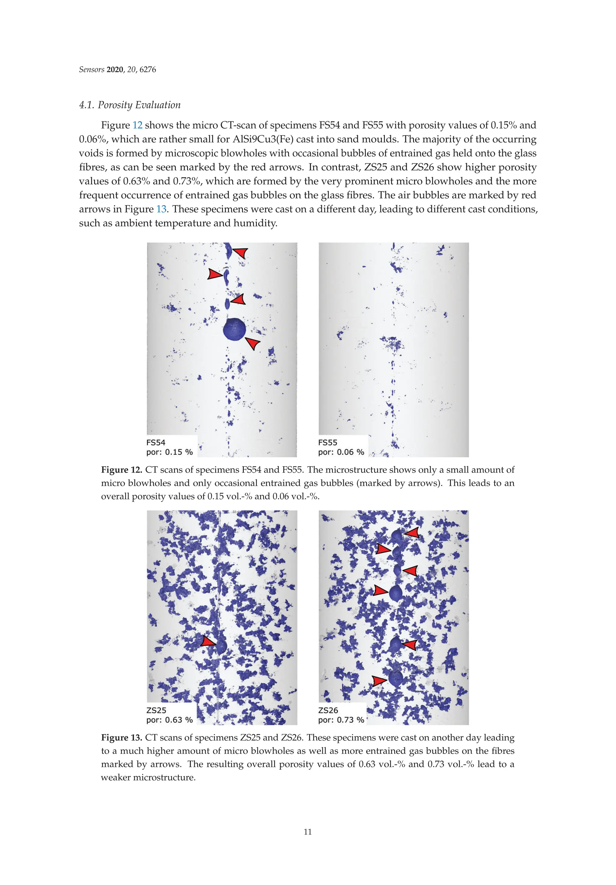
![Sensors 2020, 20, 6276
4.2. Strain Evaluation during Tensile Testing
The tensile tests enable the comparison of three independent strain measurement techniques.
The extensometer data represent the macroscopic behaviour of the specimens under external load.
The cast-in FBGs provide strain information from within the specimens. The phase-specific straining is
given by neutron diffraction with two different gauge volumes around the fibre. Each strain evolution
consists of two data sets measured by specimens obtained from one casting, which were unified using
a fitting curve given by Equation (8).
The tensile test routine presented in Table 3 leads to strain reactions, which are shown in Figure 14
for FS54 and FS55. Figure 14a depicts the phase-specific strains within the Al311-crystallites. AlSi
alloys commonly show heterogeneous microstructures, which combines stiff Si particles with ductile
α-aluminium into a composite with a combined strength, see Schöbel et al. [37]. Due to the ductility of
the α-aluminium, which is measured specifically by neutron diffraction in form of the Al311-reflection,
the measured strains in Figure 14a are smaller than the macroscopic strains depicted in Figure 14b.
The big and small gauge volumes both show similar in situ strain reactions, whereby the small volume
generates slightly smaller values. The similar strains can be explained by the small amount of porosity
as depicted by Figure 12, leading to an even strain distribution over the gauge volumes. The simulated
strain data show very good agreement with the measured data, where only the last two load steps
are overvalued by up to 340 × 10−6 m/m. The ex situ data of Al311 show compressive strains, which
is a microscopic reaction to the presence of silicon-rich precipitations within the alloy. Due to the
homogeneous material model within the simulation, this effect cannot be accurately recreated and
thus the elastic strains take on a value of zero when the force is relieved.
Figure 14. Straining of specimens FS54 and FS55 under tensile load steps until fatigue. The figure
shows both the comparison of in situ and ex situ data obtained by (a) neutron diffraction and (b) by
extensometer and FBG. The simulation does not consider the microstructure of the aluminium and
thus the microscopic straining does not show any permanent strains. Besides that, the calculated data
in (b) match the measured strains well. The measured strain reactions have been fitted by Equation (8).
12](https://image.slidesharecdn.com/25327745-250524183759-d847efeb/75/Fiber-Bragg-Grating-Based-Sensors-And-Systems-Oleg-Morozov-27-2048.jpg)
![Sensors 2020, 20, 6276
The straining obtained from FBG and extensometer is depicted in Figure 14b. The data show
good agreement between FBG and extensometer, meaning that cast-in FBG are perfectly capable of
measuring precise strain data conforming to standards [38]. The maximum in situ straining shows
values as high as 7000 × 10−6 m/m. This data point is used to calibrate the simulation model,
from which all other calculated strain values arise.
The ex-situ straining shows the plastification of the specimens, beginning at tensions higher than
40 MPa. Both extensometer and FBG recognize plastic strains in the form of a permanent deformation,
which remains after strain relief as ex situ straining. Here, again, the calculated strain data perfectly
match the measured data. Due to the small amount of porosity within specimens FS54 and FS55,
the strain calculations were obtained from the simulation model without porosity.
Concerning specimens ZS25 and ZS26, the best fitting results were calculated by adding 1.0%
porosity to the model as described in Section 3.2. The resulting quality was evaluated with respect to
the highest in situ strain value in Figure 15b. Again, the model does not take the microstructure of the
alloy into account. Thus, the phase-specific straining of Al311 is overrated for the in situ steps and takes
on zero-values for the ex situ steps. The in situ and ex situ straining of the fibre and the extensometer,
which again show very good agreement to each other, are perfectly matched by the simulation.
Figure 15. Straining of specimens ZS25 and ZS26 under tensile load steps until fatigue. The figure
shows both the comparison of in situ and ex situ data obtained by (a) neutron diffraction and (b) by
extensometer and FBG. The calculated data include 1.0 vol.-% porosity and match the measured strains
well. The measured strain reactions have been fitted by Equation (8).
In conclusion, the results of the simulation model presented in Section 3.2 could be verified
by all the different strain measurement techniques we used during tensile testing. Especially the
phase-specific strain data obtained by neutron diffraction provides valuable support, leading to a fully
descriptive model of the interaction between glass fibre and cast aluminium. Based on these findings,
we are now able to examine the strain transition from aluminium to fibre as a function of the radius on
a microscopic scale.
13](https://image.slidesharecdn.com/25327745-250524183759-d847efeb/75/Fiber-Bragg-Grating-Based-Sensors-And-Systems-Oleg-Morozov-28-2048.jpg)
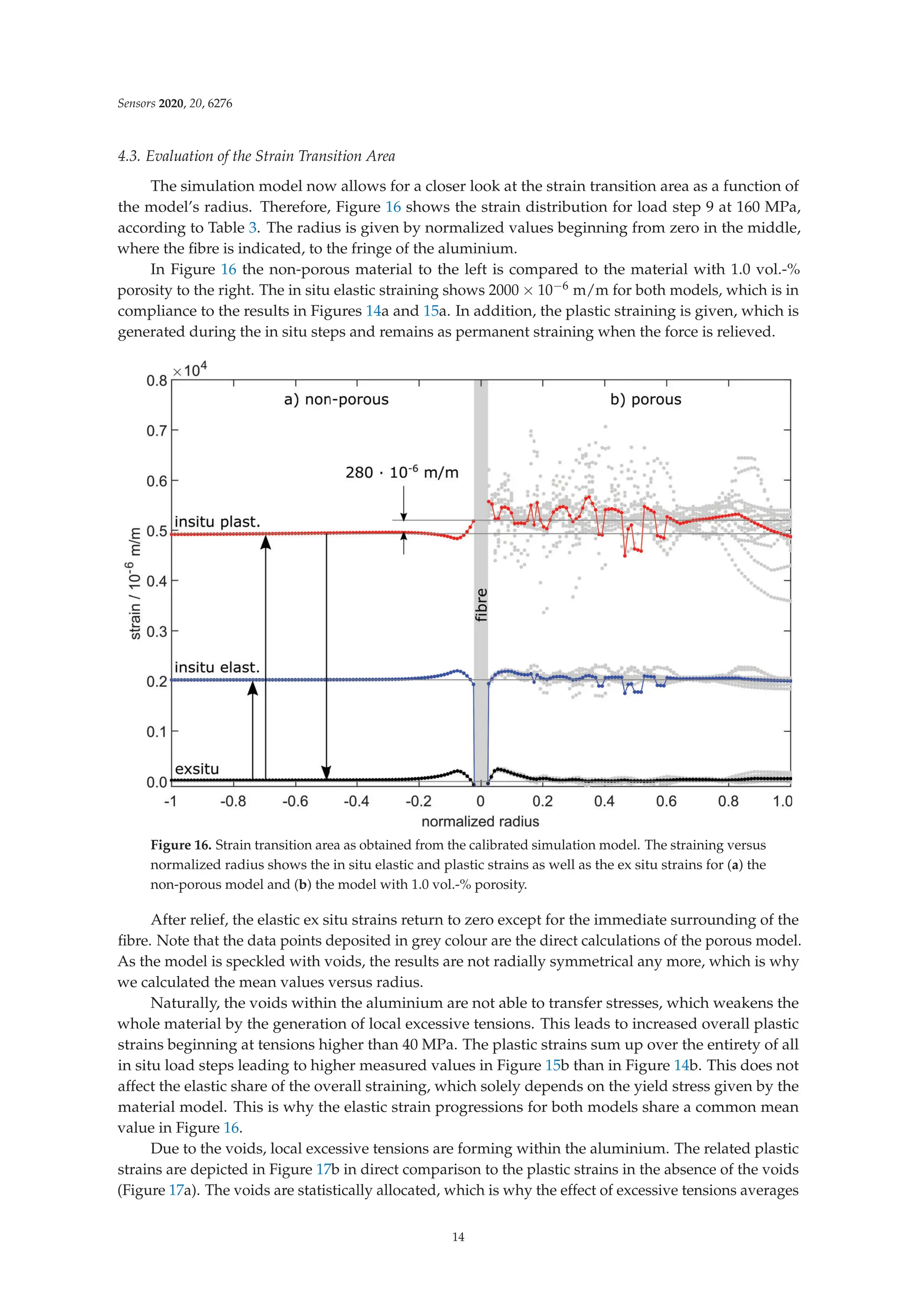
![Sensors 2020, 20, 6276
itself. The glass fibre is only affected by changing transversal tensions, which can cause a change in
the FBG’s spectrum [17]. According to Heilmeier et al. [10], this has no influence on the FBG’s axial
straining as long as only the primary peak is evaluated.
Figure 17. Microscopic plastic straining in the transition area around the glass fibre (a) without and (b)
with 1.0 vol.-% porosity. By adding voids to the model, local excessive tensions are formed, weakening
the structure of the specimen.
4.4. Spectra Analysis
Figure 18 elucidates the alteration of the FBG’s spectrum. The position of the primary peak
determined by the peakfinding algorithm is given by the black arrows. We chose specimen FS55 due
to the small defect content (see Figure 12) in order to keep the influence of porosities on the spectrum
at a minimum. All spectra are normalized using the initial peak, which is the given by the free fibre
before casting. The peak intensity after casting is beneath 40% of its original intensity. The spectrum
of the FBG after machining shows a relief of the force on the fibre, leading to a moderate rise in
the peak intensity and a shift back to higher wavelengths. This is the initial state of the FBG before
tensile testing.
In order to show the effect of the external force during tensile testing, the figure shows the
spectrum which forms during the last load step and after relief. During in situ step 9, the spectrum
shows distinct secondary peaks, which may be caused by transversal loads, strain gradients along the
Bragg grating [17] or changes in the fibre’s local photoelastic constants—see Equations (3) and (4).
The peakfinding algorithm is designed to track the primary peak, which represents the axial
straining z of the grating. This was already proven by Heilmeier et al. [10] and can be directly seen
by the agreement of the strain measurements in Figures 14b and 15b. The cause of the occurring
secondary peaks, however, has to be determined by further experiments. After relief, the spectrum
obviously reshapes to a less distorted peak. This may be a proof for the secondary peaks to be caused
by transversal strains, as the lateral contraction of the tensile specimen reduces after relief.
15](https://image.slidesharecdn.com/25327745-250524183759-d847efeb/75/Fiber-Bragg-Grating-Based-Sensors-And-Systems-Oleg-Morozov-30-2048.jpg)
![Sensors 2020, 20, 6276
Figure 18. FBG-spectra obtained from every intermediate condition of the specimen before and
during testing. The spectrum shows a decrease in reflectivity and degenerates with an increased load
subsequently, where secondary peaks are formed beside the primary peak (marked by a black arrow
for each step).
5. Discussion
The calculations show that increased plastic strains are generated by the voids within the
aluminium due to local excessive tensions. This greatly affects the macroscopic behaviour of the
specimens and thus the strain measurements by extensiometer and FBG—see Figures 14b and 15b.
Apparently, the microscopic strain distribution only affects the aluminium, as the glass fibre only
shows changes in macroscopic strains. Obviously, the casting’s supporting effect is still granted in the
presence of pores, as the glass fibre would otherwise have breached.
Above a tension of 40 MPa, plastic strains are generated, which build up during the in situ
steps. The total plastic strain is then retained as total strain information within the glass fibre.
Obviously, the strain transition between aluminium and fibre is not affected by the porosity. There
is rather the effect of increased plastification of the specimens which, of course, cannot be directly
detected during continuous tensile testing. Regarding [10], only in situ data were generated during
testing, making it impossible to decouple plastic and elastic strains afterwards.
The wide range of porosity values between 0 vol.-% and 2 vol.-% can now explain the variation of
calibration factors. This claim is sustained by [13], which states that the overall defect volume has a
greater influence on the strain response of the cast-in FBG than the defect area directly on the fibre.
Nevertheless, the difference between strains measured by FBG and extensometer has not yet been
clarified. This may be due to stick-slip effects, which we could not verify in our simulation.
Although the statement of the simulation is valid and provides quantitative results,
the microscopic strain distribution highly depends on the shape and distribution of the voids
within the model. This may have a small impact on the local microscopic strains, but sums up
to a macroscopic difference in the overall straining and stiffness of the specimen. The validation
in Figures 14 and 15 shows excellent agreement between measurement and simulation and yields
valuable information about the strain transition area. Thus, the FE-model closes the gap between
microscopic and macroscopic straining. Of particular significance is the statement that cast-in FBG
behaves like the external strain measurement method given by extensometer. The microstructure of the
surrounding aluminium and the external load condition do affect the reflected spectra obtained from
the Bragg grating. However, the strain measurement by FBG is not compromised if the primary peak is
16](https://image.slidesharecdn.com/25327745-250524183759-d847efeb/75/Fiber-Bragg-Grating-Based-Sensors-And-Systems-Oleg-Morozov-31-2048.jpg)
![Sensors 2020, 20, 6276
reliably tracked during the spectra analysis. Other than Lammens et al., who investigated transversal
strains during the curation of cross-ply composites [39], we only focus on the distinct detection of
the primary peak in this work, which represents the axial straining z. Nevertheless, if the occurring
secondary peaks can be reliably related to transversal strains, the peak-finding method we used could
be of certain interest for the evaluation of embedded FBGs.
6. Conclusions
In recent research, cast-in FBG showed a wide dispersion of calibration factors. In this research,
we examined the question on how the strain transition from aluminium to fibre forms during tensile
testing. Microscopic porosity has a great impact on the local microstrains generated. Both effects
were evaluated by a calibrated finite element simulation, which is based on both the measurement of
phase-specific strains using neutron diffraction and macrostrains by the extensometer, as well as FBG.
As a result, we were able to identify and decouple elastic and plastic strains affecting the FBGs.
The experiments show that plastic strains develop at tensions higher than 40 MPa. Plastic strains
remain permanently within the specimen and add up over all load steps. Because the fibre has a
force-locked connection to the surrounding casting due to shrinkage after solidification, the FBG shows
the same permanent straining in the plastic deformation regime of the specimen as the external strain
measurement by extensometer.
Because of local excessive tensions in presence of pores regions more plastic straining is transferred
into the FBG. This is shown by the FE simulation, which gives evidence of the local stress and strain
distribution in the transition area, especially in the direct surroundings of the glass fibre. The content
of porosity within the casting turns out to be the main influence on the straining of the fibre, which is
then measured by the Bragg grating.
The porosity affects neither the calculated nor the measured phase-specific elastic strains of the
aluminium crystallites. The mechanisms of plastification do not occur within the aluminium grains,
but in between. This is why neutron diffraction is only able to measure elastic strains, which turn out
to be independent from the pore content. This is substantiated by simulation, which is not able to show
the microscopic, inter-granular ex situ strains within the aluminium, though. An interesting extension
of the simulation model would hence consider a heterogeneous microstructure of the aluminium.
In conclusion, we accomplished to close the gap between the external load and internal straining
obtained from cast-in FBG by development of a fully descriptive FE-model considering the contact
between casting and glass fibre. This enables the generation of valuable information about the
mechanisms within the strain transition obtained from the strain evolutions directly around the fibre.
We see that the porosity has a significant impact on the stiffness of the tensile specimen, the generation
of excess tensions and thus the formation of permanent plastic strains, which are well recognized by
the FBG. The knowledge that FBG as internal strain sensors function just as common external strain
sensors will allow the application of FBG in actual structural parts and measurements under real load
conditions. In future, applications for long-term monitoring of cast parts will also be enabled and are
currently under development.
Author Contributions: F.H. and R.K. conceived and designed the experiments. F.H., R.K. and M.S. performed the
experiments. M.S. and F.H. performed the simulation. P.H. and J.H. provided the CT scans as well as the porosity
analysis. F.H., R.K. and C.B. analyzed the data. W.V. coordinated the project and discussed the theory. All authors
have read and agreed to the published version of the manuscript.
Funding: This work was funded by the Deutsche Forschungsgemeinschaft (DFG) [Grant Nos. VO 1487/11-1 and
VO 1487/11-2].
Conflicts of Interest: The authors declare that they have no known competing financial interests or personal
relationships that could have appeared to influence the work reported in this paper.
17](https://image.slidesharecdn.com/25327745-250524183759-d847efeb/75/Fiber-Bragg-Grating-Based-Sensors-And-Systems-Oleg-Morozov-32-2048.jpg)
![Sensors 2020, 20, 6276
References
1. Warnke, E. Mit Eigenspannungen leben: Entstehung, Auswirkungen, Messung, Berechnung und
Vermeidung von Eigenspannungen, Ausblick. In Konstruieren und Giessen; Bundesverband der Deutschen
Gießerei-Industrie: Düsseldorf, Germany, 2008; pp. 37–40.
2. Weraneck, K.; Heilmeier, F.; Lindner, M.; Graf, M.; Jakobi, M.; Volk, W.; Roths, J.; Koch, A.W.
Strain Measurement in Aluminium Alloy during the Solidification Process Using Embedded Fibre Bragg
Gratings. Sensors 2016, 16. [CrossRef]
3. Luyckx, G.; Voet, E.; Lammens, N.; Degrieck, J. Strain measurements of composite laminates with embedded
fibre bragg gratings: Criticism and opportunities for research. Sensors 2011, 11, 384–408. [CrossRef]
4. Prussak, R.; Stefaniak, D.; Kappel, E.; Hühne, C.; Sinapius, M. Smart cure cycles for fiber metal laminates
using embedded fiber Bragg grating sensors. Compos. Struct. 2019, 213, 252–260. [CrossRef]
5. Mulle, M.; Yudhanto, A.; Lubineau, G.; Yaldiz, R.; Schijve, W.; Verghese, N. Internal strain assessment
using FBGs in a thermoplastic composite subjected to quasi-static indentation and low-velocity impact.
Compos. Struct. 2019, 215, 305–316. [CrossRef]
6. Li, F.; Du, Y.; Sun, X.; Zhao, W. Sensing performance assessment of twisted CFRP with embedded fiber Bragg
grating sensors subjected to monotonic and fatigue loading. Sens. Actuators A Phys. 2018, 271, 153–161.
[CrossRef]
7. Nair, A.; Cai, C.S.; Kong, X.; Hou, S. Bridge Retrofitting Using FRP-Wrapped Balsa Wood Deck: Experimental
Study and Field Evaluation. J. Aerosp. Eng. 2019, 32, 04019065. [CrossRef]
8. Cinitha, A.; Sampath, V.; Kesavan, K. Strain monitoring of low carbon steel in a corrosive environment using
fiber Bragg technology. Constr. Build. Mater. 2019, 217, 265–272. [CrossRef]
9. Zhou, X.; Yu, Q.; Peng, W. Fiber-optic Fabry—Perot pressure sensor for down-hole application.
Opt. Lasers Eng. 2019, 121, 289–299. [CrossRef]
10. Heilmeier, F.; Koos, R.; Weraneck, K.; Lindner, M.; Jakobi, M.; Roths, J.; Koch, A.W.; Volk, W. In-situ
strain measurements in the plastic deformation regime inside casted parts using fibre-optical strain sensors.
Prod. Eng. 2019, 618, 271. [CrossRef]
11. Jülich, F.; Aulbach, L.; Wilfert, A.; Kratzer, P.; Kuttler, R.; Roths, J. Gauge factors of fibre Bragg grating strain
sensors in different types of optical fibres. Meas. Sci. Technol. 2013, 24, 094007. [CrossRef]
12. Deutsches Institut für Normung e.V. Aluminium und Aluminiumlegierungen—Chemische Zusammensetzung
und Mechanische Eigenschaften; Beuth Verlag GmbH: Berlin, Germany, 2019.
13. Heilmeier, F.; Koos, R.; Hornberger, P.; Hiller, J.; Weraneck, K.; Jakobi, M.; Koch, A.W.; Volk, W. Calibration of
cast-in fibre Bragg gratings for internal strain measurements in cast aluminium by using neutron diffraction.
Measurement 2020, 163, 107939. [CrossRef]
14. Weraneck, K. Strukturüberwachung Mittels Eingebetteter Faser-Bragg-Gitter; Universitätsbibliothek der TU
München: München, Germany, 2018.
15. Erdogan, T. Fiber grating spectra. J. Light. Technol. 1997, 15, 1277–1294. [CrossRef]
16. Rao, Y.J. In-fibre Bragg grating sensors. Meas. Sci. Technol. 1997, 8, 355–375. [CrossRef]
17. Wagreich, R.B.; Sirkis, J.S. Distinguishing Fiber Bragg Grating Strain Effects. In Proceedings of the 12th
International Conference on Optical Fiber Sensors, Williamsburg, VA, USA, 28–31 October 1997; pp. 20–23.
[CrossRef]
18. Werneck, M.; Allil, R.C.S.B.; Ribeiro, B.A.; de Nazaré, F.V.B. A Guide to Fiber Bragg Grating Sensors.
In Current Trends in Short- and Long-Period Fiber Gratings; Cuadrado-Laborde, C., Ed.; IntechOpen: London,
UK, 2013. [CrossRef]
19. Mondal, D.P.; Jha, N.; Badkul, A.; Das, S. Effect of Al—TiB master alloy addition on microstructure,
wear and compressive deformation behaviour of aluminum alloys. Trans. Nonferrous Met. Soc. China 2012,
22, 1001–1011. [CrossRef]
20. Randau, C. Entwicklungen am Neutronendiffraktometer STRESS-SPEC für Schnelle und Lokale
Polfigurmessungen zur Bestimmung Ortsaufgelöster Texturen: Dissertation. Ph.D. Thesis, Technische
Universität Clausthal, Clausthal, Germany, 2012.
21. Röhrmoser, A. Core model of new German neutron source FRM II. Nucl. Eng. Des. 2010, 240, 1417–1432.
[CrossRef]
18](https://image.slidesharecdn.com/25327745-250524183759-d847efeb/75/Fiber-Bragg-Grating-Based-Sensors-And-Systems-Oleg-Morozov-33-2048.jpg)
![Sensors 2020, 20, 6276
22. Gabrys, B.J. Applications of Neutron Scattering to Soft Condensed Matter; Chapman and Hall/CRC: Boca Raton,
FL, USA, 2014.
23. Meier, L. In-Situ-Messung der Phasenumwandlungskinetik von Ausferritischem Guasseisen; utg-Forschungsberichte;
Shaker Verlag: Aachen, Germany, 2017; Volume 76.
24. Bragg, W.H.; Bragg, W.L. The Reflection of X-rays by Crystals. Proc. R. Soc. A Math. Phys. Eng. Sci. 1913,
88, 428–438. [CrossRef]
25. ISO International Organization for Standardization. Non-Destructive Testing: Standard Test Method for
Determining Residual Stresses by Neutron Diffraction; ISO: Geneva, Switzerland, 2005.
26. Hanke, R.; Fuchs, T.; Salamon, M.; Zabler, S. X-ray microtomography for materials characterization.
In Materials Characterization Using Nondestructive Evaluation (NDE) Methods; Woodhead Publishingr: Sawston,
Cambridge, 2016; pp. 45–79. [CrossRef]
27. Buzug, T. Computed Tomography: From Photon Statistics to Modern Cone-Beam CT; Springer: Berlin/Heidelberg,
Germany, 2008. [CrossRef]
28. Rodet, T.; Noo, F.; Defrise, M. The cone-beam algorithm of Feldkamp, Davis, and Kress preserves oblique
line integrals. Med. Phys. 2004, 31, 1972–1975. [CrossRef]
29. Feldkamp, L.A.; Davis, L.C.; Kress, J.W. Practical cone-beam algorithm. J. Opt. Soc. Am. A 1984, 1, 612.
[CrossRef]
30. Lange, K.; Pöhlandt, K. Vergleichende Betrachtung der Verfahren zur Prüfung der Plastischen Eigenschaften
Metallischer Werkstoffe; Springer: Berlin/Heidelberg, Germany, 1984; Volume 80. [CrossRef]
31. Papula, L. Mathematik für Ingenieure und Naturwissenschaftler; Vieweg+Teubner Verlag: Wiesbaden, Germany,
2011. [CrossRef]
32. Hofmann, M.; Schneider, R.; Seidl, G.A.; Rebelo-Kornmeier, J.; Wimpory, R.C.; Garbe, U.; Brokmeier, H.G.
The new materials science diffractometer STRESS-SPEC at FRM-II. Phys. B Condens. Matter 2006,
385–386, 1035–1037. [CrossRef]
33. Hoelzel, M.; Gan, W.M.; Hofmann, M.; Randau, C.; Seidl, G.; Jüttner, P.; Schmahl, W.W. Rotatable
multifunctional load frames for neutron diffractometers at FRM II—Design, specifications and applications.
Nucl. Instrum. Methods Phys. Res. Sect. A Accel. Spectrometers Detect. Assoc. Equip. 2013, 711, 101–105.
[CrossRef]
34. Reihle, M.M. Entstehung und Ausprägung von Eigenspannungen in Verbundgussteilen. Ph.D. Thesis,
Technische Universität München, Munich, Germany, 2016.
35. Firsching, M.; Salamon, M.; Keßling, P.M.; Nachtrab, F.; Krumm, M.; Uhlmann, N.; Hanke, R. Micro
Structural Analysis of AlSi6Cu4 Using Quantitative Computed Tomography Methods; Fraunhofer IIS: Erlangen,
Germany, 2010.
36. Reinhart, C. VGStudio MAX Referenzhandbuch; Volume Graphics GmbH: Heidelberg, Germany, 2018.
37. Schöbel, M.; Baumgartner, G.; Gerth, S.; Bernardi, J.; Hofmann, M. Microstresses and crack formation in
AlSi7MgCu and AlSi17Cu4 alloys for engine components. Acta Mater. 2014, 81, 401–408. [CrossRef]
38. Deutsches Institut für Normung e.V. Metallische Werkstoffe—Zugversuch: Teil 1: Prüfverfahren bei
Raumtemperatur; Beuth-Verlag GmbH: Berlin, Germany, 2019.
39. Lammens, N.; Kinet, D.; Chah, K.; Luyckx, G.; Caucheteur, C.; Degrieck, J.; Mégret, P. Residual strain
monitoring of out-of-autoclave cured parts by use of polarization dependent loss measurements in embedded
optical fiber Bragg gratings. Compos. Part A Appl. Sci. Manuf. 2013, 52, 38–44. [CrossRef]
Publisher’s Note: MDPI stays neutral with regard to jurisdictional claims in published maps and institutional
affiliations.
© 2020 by the authors. Licensee MDPI, Basel, Switzerland. This article is an open access
article distributed under the terms and conditions of the Creative Commons Attribution
(CC BY) license (http://creativecommons.org/licenses/by/4.0/).
19](https://image.slidesharecdn.com/25327745-250524183759-d847efeb/75/Fiber-Bragg-Grating-Based-Sensors-And-Systems-Oleg-Morozov-34-2048.jpg)

![sensors
Article
On the Evaluation of a Coupled Sequential Approach
for Rotorcraft Landing Simulation
Demetrio Cristiani 1 , Luca Colombo 1 , Wojciech Zielinski 2, Claudio Sbarufatti 1,*,
Francesco Cadini 1, Michal Dziendzikowski 2 and Marco Giglio 1
1 Dipartimento di Meccanica, Politecnico di Milano, 20156 Milano, Italy;
demetrioluigi.cristiani@polimi.it (D.C.); luca1.colombo@polimi.it (L.C.); francesco.cadini@polimi.it (F.C.);
marco.giglio@polimi.it (M.G.)
2 Air Force Institute of Technology, Airworth, Division, 01-494 Warsaw, Poland;
wojciech.zielinski@itwl.pl (W.Z.); michal.dziendzikowski@itwl.pl (M.D.)
* Correspondence: claudio.sbarufatti@polimi.it; Tel.: +39-022399-8213
Received: 31 March 2020; Accepted: 26 April 2020; Published: 29 April 2020
Abstract: Maximum loads acting on aircraft structures generally arise when the aircraft is undergoing
some form of acceleration, such as during landing. Landing, especially when considering rotorcrafts,
is thus crucial in determining the operational load spectrum, and accurate predictions on the actual
health/load level of the rotorcraft structure cannot be achieved unless a database comprising the
structural response in various landing conditions is available. An effective means to create a structural
response database relies on the modeling and simulation of the items and phenomena of concern.
The structural response to rotorcraft landing is an underrated topic in the open scientific literature,
and tools for the landing event simulation are lacking. In the present work, a coupled sequential
simulation strategy is proposed and experimentally verified. This approach divides the complex
landing problem into two separate domains, namely a dynamic domain, which is ruled by a multibody
model, and a structural domain, which relies on a finite element model (FEM). The dynamic analysis
is performed first, calculating a set of intermediate parameters that are provided as input to the
subsequent structural analysis. Two approaches are compared, using displacements and forces at
specific airframe locations, respectively, as the link between the dynamic and structural domains.
Keywords: fiber Bragg gratings; landing simulation; rotorcraft; coupled sequential method; landing
structural response; finite element analysis (FEA)
1. Introduction
Landing event characterization is fundamental when aircraft structural assessment has to be
performed. Load spectra are inherently affected by landings, and their accurate determination cannot
be pursued without considering the landing event itself. Indeed, depending on the landing severity
and occurrence, the structure might be subjected to high stress levels and non-negligible performance
degradation caused by material damage, especially when the landing ranks in the harsh landing
regime. The definition of harsh landing is still neither clearly defined nor well-established and is
generally considered as a phenomenon that occurs whenever the landing event induces abnormal
operational conditions. Whether these conditions are related to the aircraft’s structural response only or
also involve the passengers’ comfort is a matter of debate. Harsh landing can thus be generally located
in between normal landing operations and crash events. More specifically, harsh landing is defined by
the regulatory authorities in EASA Certification Specification (CS) 25 and Federal Aviation Regulations
(FAR) 25 as a landing with a vertical descent velocity exceeding 3 m/s [1,2]. The same threshold is
used in the Aircraft Crash Survival Design Guide (Volume 3—Aircraft Structural Crash Resistance) [3].
Sensors 2020, 20, 2540; doi:10.3390/s20092540 www.mdpi.com/journal/sensors
21](https://image.slidesharecdn.com/25327745-250524183759-d847efeb/75/Fiber-Bragg-Grating-Based-Sensors-And-Systems-Oleg-Morozov-36-2048.jpg)
![Sensors 2020, 20, 2540
However, this definition is not sufficient when the landing structural response is concerned, since the
vertical descent rate alone is not the unique parameter influencing the landing severity. The structural
response to landing depends on multiple variables; the total aircraft weight, the mass distribution,
the landing attitude (i.e., the pitch and roll angles), the weight to lift ratio, the forward and lateral
landing velocities (generally null or negligible when rotorcrafts are considered), the pitch, roll and yaw
rates (if non-negligible), and other parameters related to the environment, have proven to be crucial
for the landing assessment.
Nowadays, the flight crew judges the classification of the landing, and eventually establishes if
the landing was harsh or not [4,5]. This judgment is generally based on subjective perception, and
even when it is supported by objective data, these are insufficient to assess the structural response to
landing accurately. This can lead to a biased classification of the landing conditions, thus affecting the
safety of the system or leading to unnecessary time and money consuming maintenance procedures.
Hence the need to be fully aware of the landing structural response. Precise knowledge of the landing
event structural consequences might result in considerable economic savings and increased system
safety, since maintenance would be undertaken only when necessary, and based on objective data
evaluation, allowing the current maintenance philosophies to evolve into potentially more cost-effective
condition-based maintenance philosophies. Understanding the relationship between the landing
characteristics and their structural consequences will enable not only the estimation of the actual aircraft
aging, as well as an objective classification of the landing, but furthermore the potential occurrence
of structural failures, thus paving the way for the implementation of health and usage monitoring
systems (HUMS).
In general, any monitoring system entails the observation of a structure over time using periodical
measurements, the extraction of proper features from these measurements and the analysis and
interpretation of these features to determine the current state of the system, whether the focus is
on its health state or its load level [6,7]. The actual state of the investigated system can often result
from a statistical comparison of the current data with a database of experimental data. The latter,
depending on the examined system and on the variety of circumstances it operates in, might be
economically unsustainable, as well as time-consuming to be obtained. An efficient solution to this
problem lies in mathematical modeling. Indeed, using numerical models and proper simulation
strategies, it is possible to virtually reproduce the phenomena of concern, developing a database of the
structural response based on the most influential landing features, consistently limiting the costs of
an experimental campaign. The modeling and simulation of the investigated system also allow to (i)
select the most suited sensor technology, (ii) predict, in the modeling space, the sensitivity of some
parameters to the features of interest, (iii) design and optimize the monitoring system.
This work aims to provide an analysis method for simulating, investigating and characterizing the
landing event of a medium-size rotorcraft (Mil Mi-8 helicopter), both from a dynamic and structural
point of view, thus leading the way for future implementation of load monitoring (LM) and structural
health monitoring (SHM) systems. Specifically, the present work addresses the landing operational
range which spans between the nominal landing operations and the harsh landings. These are
determined based on the structural consequences the landing has on the airframe. The present
framework is enhanced by full-scale experimental tests carried out on a Mil Mi-8 helicopter, which
allowed the numerical models of the examined aircraft to be evaluated and verified, proving the
legitimacy of the hereafter described method.
More specifically, the landing problem field is divided into two separate domains, namely the
dynamic and the structural domain. According to the pursued strategy, the dynamic domain, which
relies on a multibody model of the aircraft, takes as an input the main landing characterizing features,
and (i) it returns the dynamic response to the landing event; (ii) it provides the structural domain with
the proper parameters to assess the landing event structural response. This strategy provides a tool
that can predict the landing structural response based on some characteristic landing parameters.
22](https://image.slidesharecdn.com/25327745-250524183759-d847efeb/75/Fiber-Bragg-Grating-Based-Sensors-And-Systems-Oleg-Morozov-37-2048.jpg)
![Sensors 2020, 20, 2540
The present work is structured as follows: first, the state of the art of the subject and the related
topics is given, then the landing event analysis method is presented, followed by the illustration of an
insight of the experimental activity. Subsequently, the modeling of the aircraft landing is examined,
and the dynamic and structural domains are investigated. Finally, a conclusive section is provided.
2. State of the Art
The rotorcraft open literature lacks a comprehensive method able to describe and simulate the
landing event from both a dynamic and structural point of view. Furthermore, general studies
on the simulation strategies of unconstrained aircraft structures subjected to landing loads are
lacking. Concerning rotorcraft landing simulation related topics, the open literature mainly covers
two types of research lines: (i) crashworthiness related research activities, which usually consist of
experimental activities (e.g., full-scale crash tests), modeling (FE models) and simulation of the crash
event; (ii) research activities related to the dynamics of the rotorcraft during the landing, such as the
rotorcraft-ground interaction and the development and optimization of landing gears design.
Crashworthiness related research activities date back to the pioneering work of Hugh De Haven in
the 1940s [8], which provided design guidelines that are still pertinent [9,10]. Aviation crash dynamics
research, besides the experimental crash assessment of already existing aircraft, is aimed at providing
meaningful design guidelines to make the aircraft structures crashworthy, minimizing the harm to the
passengers [11,12], as illustrated in the Aircraft Crash Survival Design Guide [3], which is considered
to be a milestone in its field [9]. Apart from full-scale crash experimental tests, in recent decades,
research activity has been mainly oriented towards the development of analytical/computational tools
for the accurate simulation of an airframe structural response to crash loads [13–15]. Resources have
been invested in the validation of numerical simulations and models [14,16,17], which are nowadays
supported by powerful, efficient and relatively economic calculators. Virtual modeling and simulation
allow us to evaluate numerous situations that are economically unfeasible with full-scale crash testing.
However, full-scale experimental tests are still the unique procedure which allows the numerical
models to be validated. The National Aeronautics and Space Administration (NASA) has been one of
the major players in the crashworthiness related research activities. The Impact Dynamics Research
Facility (IDRF) located at NASA Langley Research Center in Hampton, Virginia, witnessed decades
of full-scale crash experiments (it was converted into a full-scale crash test facility for light aircraft
and rotorcraft in the early 1970s) [18]. A significant example of FE code validation and simulation
procedures is represented by a research project which was initiated to demonstrate the capabilities of
the state-of-the-art commercial crash simulation codes in predicting the dynamic structural response of
the Sikorsky ACAP (Advanced Composite Airframe Program) helicopter, during a full-scale crash test,
in 1998. The objective of the crash simulation was to evaluate the capabilities of the code (MSC.Dytran)
in predicting the response of a composite airframe subjected to impact loading. The numerical results
were correlated with the experimental data to validate the simulation [19]. The level of agreement
obtained between the experimental and analytical data ensured the numerical modeling to be an
effective tool for the design and certification of crashworthy aircrafts structures. More focused activities
have investigated the crashworthiness of single helicopter components or sections, such as in [17,20–22].
Landing gears—mainly skid landing gears—also have been included in the crashworthiness research
programs, aiming at providing and optimizing effective structures for safe landings [23–27].
Research activities related to the dynamic response of the rotorcraft during the landing usually
focus on (i) the helicopter terrain interaction, (ii) the landing gear design and optimization, whether
the landing gear is wheel or skid equipped. These two topics are generally linked and usually rely
on models describing the rigid dynamics of the aircraft, neglecting the deformability of structures.
Concerning the landing gear related topics, in 1981 Bell Helicopters Textron published a technical report
which presented the results of an investigation summarizing the landing gear criteria for helicopters [28].
The investigation was conducted in two phases: the first phase constituted a summary of a literature
survey and the second phase consists of a design study of various landing gear configurations. Useful
23](https://image.slidesharecdn.com/25327745-250524183759-d847efeb/75/Fiber-Bragg-Grating-Based-Sensors-And-Systems-Oleg-Morozov-38-2048.jpg)
![Sensors 2020, 20, 2540
information on the landing gear characteristics identification is also present in [3,29]. Skid landing gear
operations were investigated in [25], where a multibody model of a skid landing gear is presented;
plastic bending deformations of structural members, damper behavior, and the characteristics of the
attachments with fuselage are reproduced. Simulations in different landing conditions are carried
out, and the outcomes are compared with experimental results. The investigation is performed in
various attitudes and soil conditions, and the sensitivity to soil friction factor is investigated. Another
work concerning a skid landing gear was published in 2007 by the NASA, describing an experimental
program to assess the impact performance of a skid gear for the use on the Wasp kit-built helicopter [23].
In recent years the application of automated robotic landing gears has seen the light. For instance,
in [30] a novel solution for the hard landing mitigation is proposed: the implementation of a robotic
legged landing gear system, which aims at softening the hard landings by acting as a shock absorber
with a relatively large stroke, thus allowing the aircraft to decelerate over a much larger distance
compared with a traditional landing gear system. The investigation of such a system was explored
using a multibody dynamics simulation tool. An exhaustive study on the modeling of an articulated
robot landing gear was given in [31]. Concerning the dynamic landing response, a study dealing with
the analysis of the helicopter-terrain interaction is carried out in [32]; this work analyzed the significant
aspects related to the interaction between rotorcrafts and the terrain using a typical medium weight
helicopter, with detailed wheel landing gear and full rotor dynamics, during significant maneuvers.
That work aimed to investigate the interaction between the landing devices and the terrain under
realistic conditions, and analyzing the effects of realistic ground loads on the rotor components. Other
works specifically focused on the rotorcraft harsh landing proposed interesting landing simulation
techniques [33,34], introducing on-board monitoring techniques (e.g., health monitoring systems) able
to assess the structural integrity of the helicopter fuselage [33–37]. In [38,39] a tool for aircraft hard
landing detection is suggested, being able to reveal landing gear overloads.
The present work aims at filling a void in the aircraft landing simulation open literature, proposing
an effective and efficient multidomain strategy for the landing simulation and providing an objective
evaluation of the proposed methods.
3. Method Overview
Sequential field-coupling is the combination of analyses from different engineering disciplines that
interact to solve a multidisciplinary engineering problem. When the input of one analysis belonging to
one field depends on the results from another analysis belonging to another domain, the analyses are
coupled. Sequential refers to the fact that the simulations are solved one after the other; the results
from one analysis become the input parameters (e.g., loads and boundary conditions) for the next
analysis. In the present case, the coupling is unidirectional, since data are flowing only forward, and
no backpropagation nor iteration procedures take place. The pursued approach to the landing problem
investigation can be thus defined as a “hybrid” or “sequentially-coupled” analysis approach, since
its development involves the exploitation of two different interacting fields, resulting in a solution
depending on a two-domain stepwise simulation procedure. Indeed, the complex landing problem is
divided into two separate domains, which are ruled by their respective numerical models. The former
domain is the dynamic one, which is governed by the multibody model of the rotorcraft. The multibody
model takes as an input the landing event/aircraft characterizing features (i.e., the rotorcraft vertical
touchdown velocity, mass distribution, landing attitude and weight to lift ratio), providing (i) the
dynamic response to the landing and (ii) the proper parameters to feed the structural domain with, to
perform the landing structural response. The latter domain is the structural one, which is ruled by a
finite element model, whose loads and boundary conditions are derived directly from the dynamic
analysis, as Figure 1 shows. Therefore, the described method works according to a feedforward
scheme, in which the dynamic domain precedes the structural domain, providing this last domain the
proper parameters to assess the landing from a structural point of view. According to the presented
approach, the two domains are related in both the chronological and causal planes. Indeed, there is a
24](https://image.slidesharecdn.com/25327745-250524183759-d847efeb/75/Fiber-Bragg-Grating-Based-Sensors-And-Systems-Oleg-Morozov-39-2048.jpg)
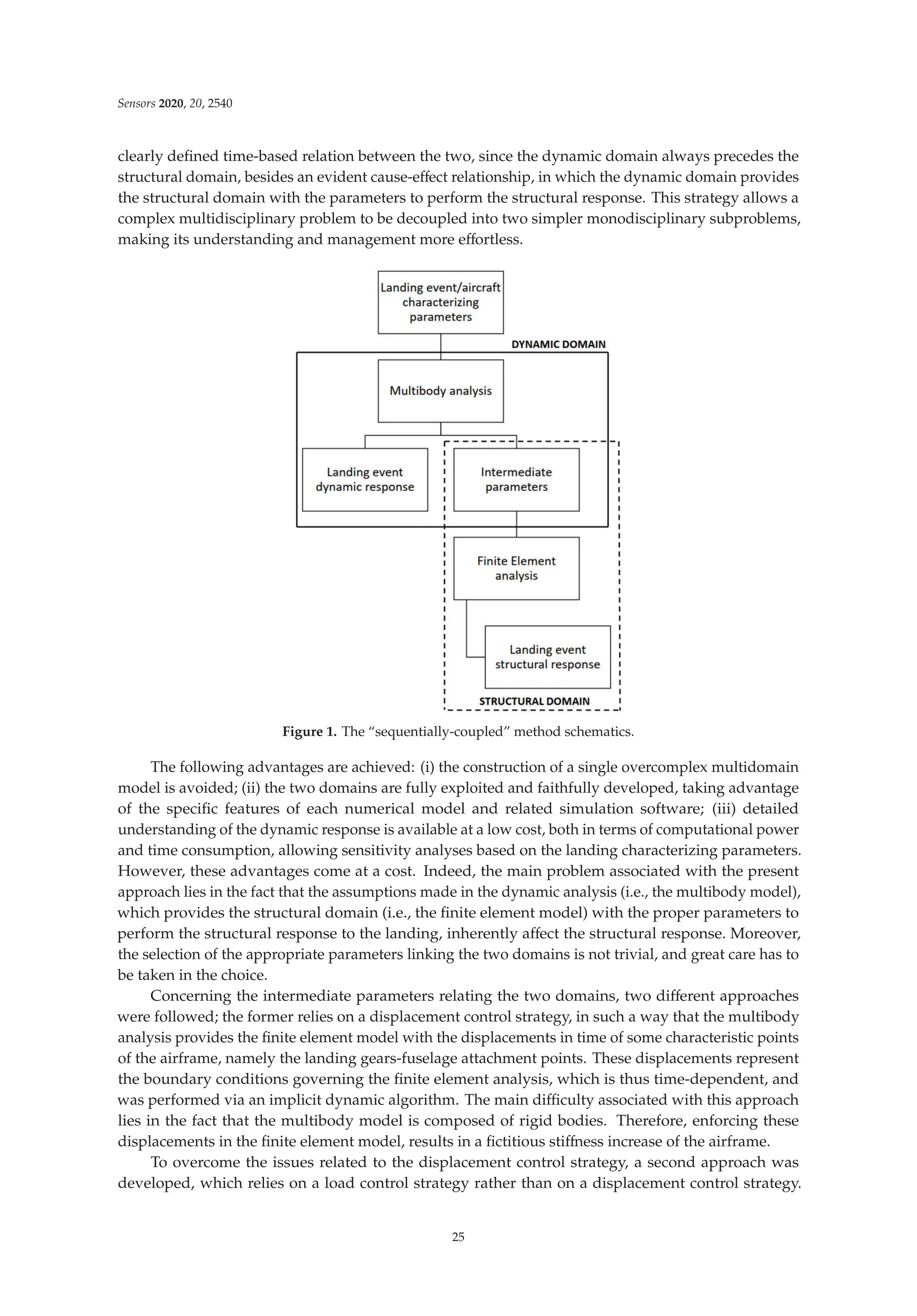
![Sensors 2020, 20, 2540
Therefore, the intermediate parameters are represented by the forces exchanged by the landing gears
and the fuselage. The structure being loaded and unconstrained, the inertia relief method was used [40].
In finite element analysis, the inertia relief method provides the response of an unconstrained structure
subjected to constant or relatively slowly varying external loads, with static analysis computational
costs. According to the inertia relief method, the unconstrained structure is assumed to be in a state
of static equilibrium; indeed, an acceleration field is computed to counterbalance the applied loads.
A set of translational and rotational accelerations provide distributed body forces over the structure
in such a way that the sum of applied forces and the sum of moments are zero. To obtain accurate
inertia relief calculation, the periods of applied loads should be much higher than the periods of rigid
body modes restrained [40], so that the dynamic structural effects can be legitimately neglected. If this
condition is not met, the inertia relief method might provide not meaningful results, since the stress
component associated with the dynamic structural response is unaccounted for. This second approach
is not exempt from issues; indeed, it does not account for the dynamic structural effects, and, unlike
dynamic analyses, it is not time-dependent.
4. Experimental Activity
The experimental activity consists of a set of full-scale drop tests of a medium-size Mil Mi-8
helicopter (Figure 2), in the fully-equipped full-load configuration, with gradually increasing drop
heights. The Mil Mi-8 helicopter is a medium-size twin-turbine helicopter with a semi-monocoque
airframe. The structure consists of an external aluminum alloy skin, stiffened with frames and stringers.
The rotorcraft is provided with a wheeled landing gear structure equipped with oleo-pneumatic shock
absorbers. The main landing gear (MLG) is equipped with a two-stage oleo-pneumatic absorber system,
i.e., two oleo-pneumatic shock absorbers placed in series. The lower cylinder has a low-pressure
low-velocity gas chamber while the upper cylinder has a high-pressure high-velocity chamber. The nose
landing gear (NLG) is composed of a single oleo-pneumatic shock absorber. Since the test required the
helicopter to be in a configuration as realistic as possible, the major subcomponents of the helicopter
were installed on the airframe, e.g., engines, gearbox, fuel equivalent mass, etc., and additional weight
representing the helicopter freight was added in the form of sandbags in the cargo compartment.
The main and tail rotor blades were substituted with equivalent lumped masses. A standard gantry
crane was used to perform the set of drops. The helicopter was connected to the gantry crane release
mechanism employing a special lug linked to the main rotor shaft-end.
Figure 2. Experimental activity. Helicopter during: maximum strut compression (a) and front-wheel
spring back (b).
The drop height was gradually increased to raise the touchdown vertical velocity. The test was
executed with the helicopter in the full weight configuration, with a total weight approximately equal
to 11,000 kg.
The experimental test consisted of a set of six drops (see Table 1), with an increased drop height,
starting from a 0 m height, in which the main landing gears wheels barely touched the ground and
the shock absorbers were fully extended, up to a 0.78 m height, which is characterized by a vertical
touchdown velocity slightly exceeding the critical one, which identifies the onset of the harsh landing
regime, as stated in the introduction, according to [1–3]. The test configuration provided a vertical
26](https://image.slidesharecdn.com/25327745-250524183759-d847efeb/75/Fiber-Bragg-Grating-Based-Sensors-And-Systems-Oleg-Morozov-41-2048.jpg)
![Sensors 2020, 20, 2540
touchdown velocity direction, as for the majority of rotary-wing landings, in which the forward speed
was either null or negligible. The test configuration was characterized by a zero-roll angle and a
positive pitch angle equal to approximately 4 degrees, which caused the main landing gear wheels to
impact the ground slightly before the nose landing gear wheels.
Table 1. List of drop experiments carried out.
Drop Height (m) Freefall Touch Down Velocity (m/s)
Theoretical Marker on Wheel Error (%)
0.00 0.00 0.00 0
0.10 1.40 1.39 −0.71
0.25 2.21 2.19 −0.90
0.35 2.62 2.61 −0.38
0.48 3.07 3.01 −1.95
0.78 3.84 3.81 −0.78
To acquire data from the experimental activity, a sensor network was designed and installed on
the helicopter.
The experimental measurements, besides displaying the dynamic and structural response of the
aircraft to the drop experiment, also allowed to link together the drop landing parameters with (i) the
parameters characterizing the dynamic response of the airframe and (ii) the stress level of the structure.
Furthermore, experimental data are essential to assess and validate the numerical models of the aircraft
itself and are also crucial to identify unknown or uncertainty affected parameters, as it is evidenced in
the following sections. Two main categories of sensors were installed: (i) dynamic response acquisition
sensors, i.e., fast camera markers, laser distance meters and shock absorbers length sensors, and (ii)
structural response acquisition sensors, e.g., fiber Bragg grating (FBG) and strain gauges (SG) sensors.
The former class of sensors was aimed at providing a collection of data that illustrate the dynamic
behavior of the aircraft during the experimental activity. In contrast, the latter class provided data
revealing the structural strains resulting from the landing event loads. Laser distance meters were fixed
on the outside of the fuselage, measuring the distance between the sensor and the ground; they were
located in three different points: in front of the nose landing gear, on the fuel tank in the proximity of
the main landing gear, and on the tail boom extremity (Table 2). The landing event was also recorded
with fast camera instrumentation (1000 frames per second); using this equipment, the displacement
in time of some markers placed on the fuselage was derived. The fast camera markers were located
near the main landing gear, more precisely at the fuel tank level, one forward and one rearward with
respect to the main landing gear. The last camera marker was placed on the main landing gear wheel
(Table 2). Shock absorbers length sensors were placed across the main landing gear shock absorbers
(two shock absorbers in series configuration), measuring the stroke of the double stage suspension
system (Table 2). The FBG sensors were placed in the most loaded areas, namely the frames 7 and 10
and the tail boom (Figure 3, Table 3); thus, three arrays of strain measuring sensors were available, for
a total of 48 sensors, of which two were designed for temperature compensation. The FBG sensors
located on the frames measured the strain along the frame circumferential direction; the ones located
on the tail boom, instead, measured the axial strain with respect to the tail boom geometry. Finally, SG
sensors were located side by side with some FBG sensors, to cross-check their measurements. Further
experimental measurements consisted of optical scanning of the skin surface in some specific areas,
performed after each drop event. Structural deformation analysis was achieved by comparing the
same scanned surface morphology before and after the landing event, to detect eventual permanent
(i.e., plastic) deformations [34,36].
27](https://image.slidesharecdn.com/25327745-250524183759-d847efeb/75/Fiber-Bragg-Grating-Based-Sensors-And-Systems-Oleg-Morozov-42-2048.jpg)
![Sensors 2020, 20, 2540
Table 2. Dynamic response sensors.
Sensor Type Sensor Location Sensor Number
Laser distance meter Nose landing gear (NLG) 1
Laser distance meter Tail boom free-end 1
Laser distance meter Lateral fuel tank (MLG) (right and left sides) 2
Fast camera marker Wheel center (right side) 1
Fast camera marker Fuselage (MLG) (right side) 1
Fast camera marker Auxiliary fuel tank (right side) 1
Shock absorbers length sensors MLG absorbers 4 (2 per side)
Figure 3. Fiber Bragg grating (FBG) sensor lines location.
Table 3. Structural response sensors.
Sensor Type Sensor Location Sensor Number
FBG Frame 7 17 (included T sensor)
FBG Frame 10 17 (included T sensor)
FBG Tail boom 14
5. The Dynamic Domain
The multibody model, being part of the dynamic domain, is aimed at providing the dynamic
response of the rotorcraft to the landing event.
5.1. The Multibody Model
The model is made up of rigid interacting bodies representing the key features of the aircraft
(Figure 4). The semi-monocoque structure is described as a rigid body to which the computed inertial
properties of the real fuselage structure were assigned. The landing gears were faithfully modeled,
including the tire behavior. The rigid body assumption made for the fuselage structure arises from the
fact that the landing gear performance, and, consequently, the general aircraft behavior, appears to
be relatively unaffected by the elastic deformation of the structure [29,41], also because the landing
gears fuselage attachments were located in strengthened zones, whose stiffness was thus increased.
The present assumption legitimacy depends on the investigated landing regime; for instance, the more
the vertical touchdown velocity is increased, the more influential the elastic structural deformation
becomes. To faithfully reproduce the experimental drop test via the multibody model, this model has
to devotedly reproduce the real aircraft features characterizing its dynamic behavior, i.e., its inertial
properties and shock absorbers characteristics.
28](https://image.slidesharecdn.com/25327745-250524183759-d847efeb/75/Fiber-Bragg-Grating-Based-Sensors-And-Systems-Oleg-Morozov-43-2048.jpg)
![Sensors 2020, 20, 2540
Figure 4. Mil Mi-8 helicopter multibody model.
5.1.1. The Inertial Properties
The multibody model inertial properties were extrapolated from the finite element model, which
is characterized by having an accurate representation of the fuselage geometry, which was obtained
via reverse engineering techniques. The semi-monocoque structure alone, including the tail boom,
stabilizers, empty fuel tanks, etc., weighs approximately 1450 kg; to reach the experimental aircraft drop
test weight of 11,000 kg, which is the in-service total full-load weight, a set of feature-representative
masses was added to the FE model of the airframe. These masses include both the helicopter equipment
and the payload. Some of the masses were modelled with solid elements, and shaped similarly to
the real ones, to devotedly reproduce their inertial properties, e.g., the engines, the main rotor, the
gearbox, etc., while others were modelled by one-dimensional elements, e.g., the payload, the tail
rotor transmission shaft, the on-board instrumentation, etc. This process is by its very nature relatively
inaccurate, and potentially introduced some errors in the modeling of the aircraft. However, the
computed inertial properties are assumed to be estimated sufficiently well for the objective of this work.
5.1.2. The Shock Absorbers Characteristics
The shock absorbers characteristics were calculated according to theoretical formulas and practical
considerations [29] and were then entered in the multibody model software (MSC ADAMS). The elastic
and damping characteristics were displayed as a set of force vs. displacement and force vs. rate of
displacement, respectively, as illustrated in Figure 5. The forces acting on the strut are here illustrated:
FS = Fh + Fa + Ff (1)
where: Fh is the hydraulic force, Fa is the pneumatic force and Ff is the friction force. The hydraulic
force in the shock strut, which is responsible for the damping characteristic, results from the pressure
difference associated with the oil flow through the orifice in the oil chamber. In a landing gear, the
orifice area is usually small enough in relation to the diameter of the strut so that the jet velocities
and Reynolds numbers are sufficiently large that the flow is fully turbulent. As a consequence, the
damping force varies as the square of the displacement rate rather than linearly. Therefore, through
the Bernoulli’s principle and considering the continuity equation, the hydraulic force can be derived:
Fh =
.
s
.
s
(ph − pa) Ah =
.
s
.
s
A3
h
.
s
2
ρ
2( Cd An)2
(2)
where: Cd is the coefficient of discharge through the orifice, An is the net orifice area (assumed here to
be constant), ρ is the hydraulic fluid density, Ah is the hydraulic area, i.e., the net area on which the
pressure difference is acting, and
.
s is the displacement rate of the shock strut. The net orifice area An
may be either a constant value (as assumed here) or, when a metering pin is used, can vary with the
strut stroke:
An(s) = A0 − Ap(s) (3)
29](https://image.slidesharecdn.com/25327745-250524183759-d847efeb/75/Fiber-Bragg-Grating-Based-Sensors-And-Systems-Oleg-Morozov-44-2048.jpg)
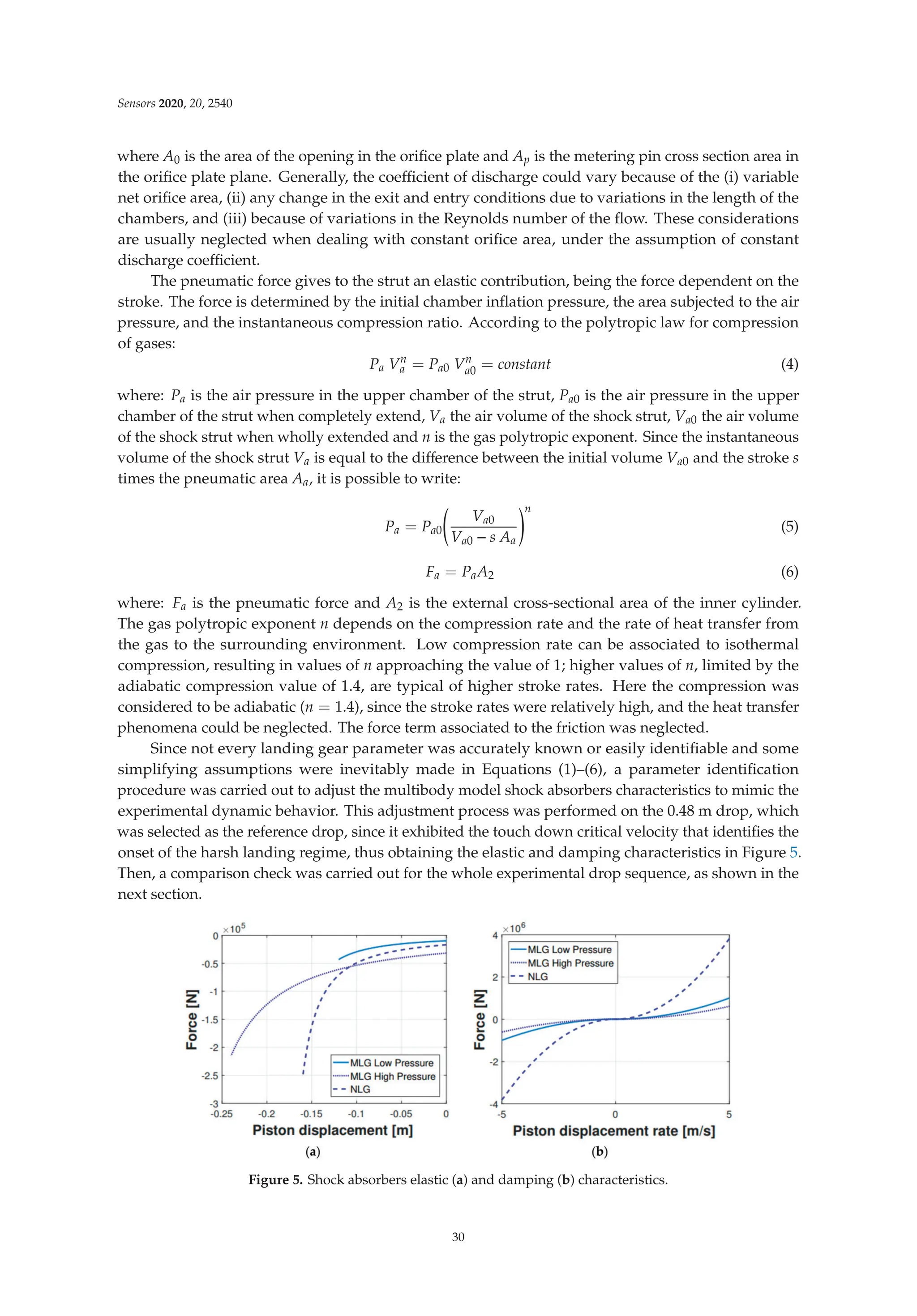
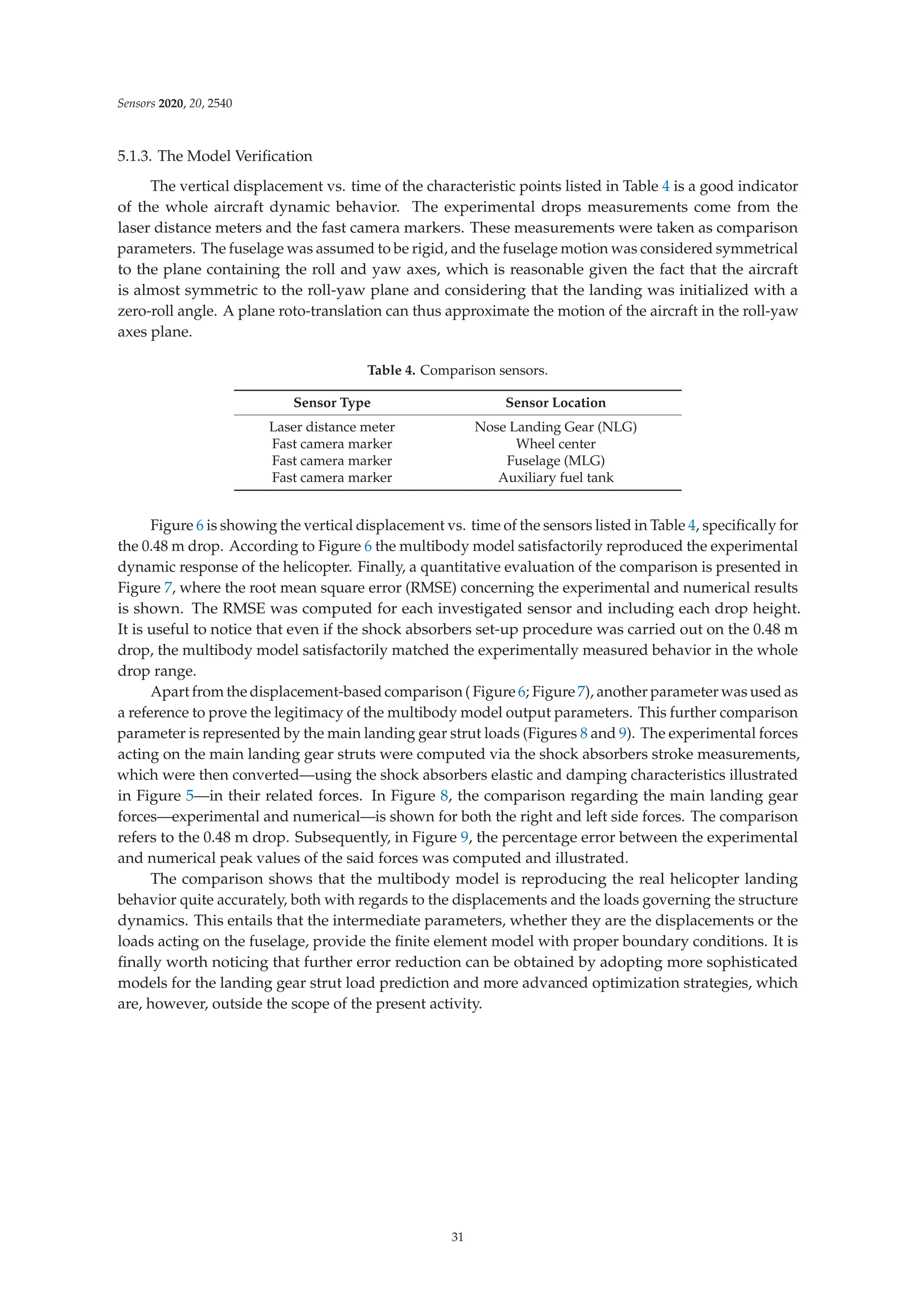
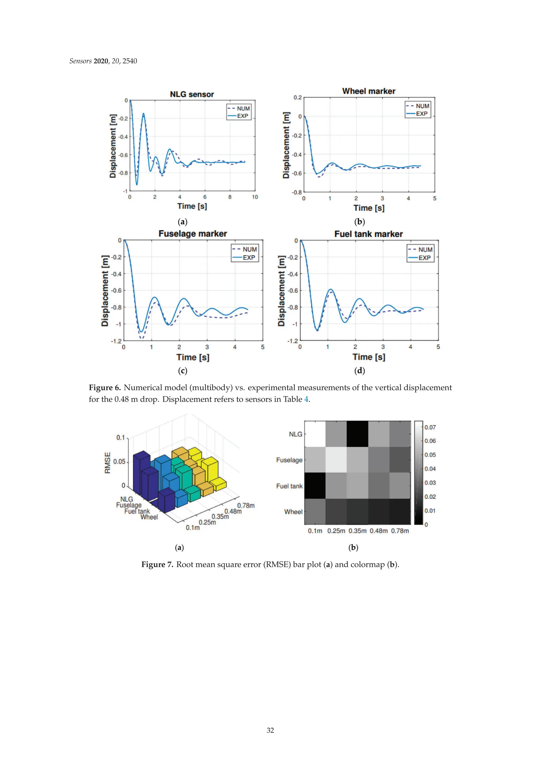
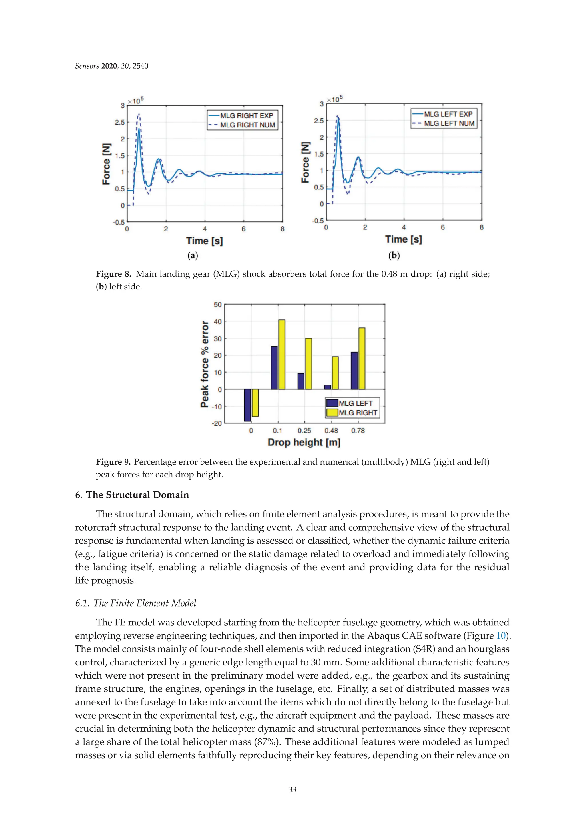
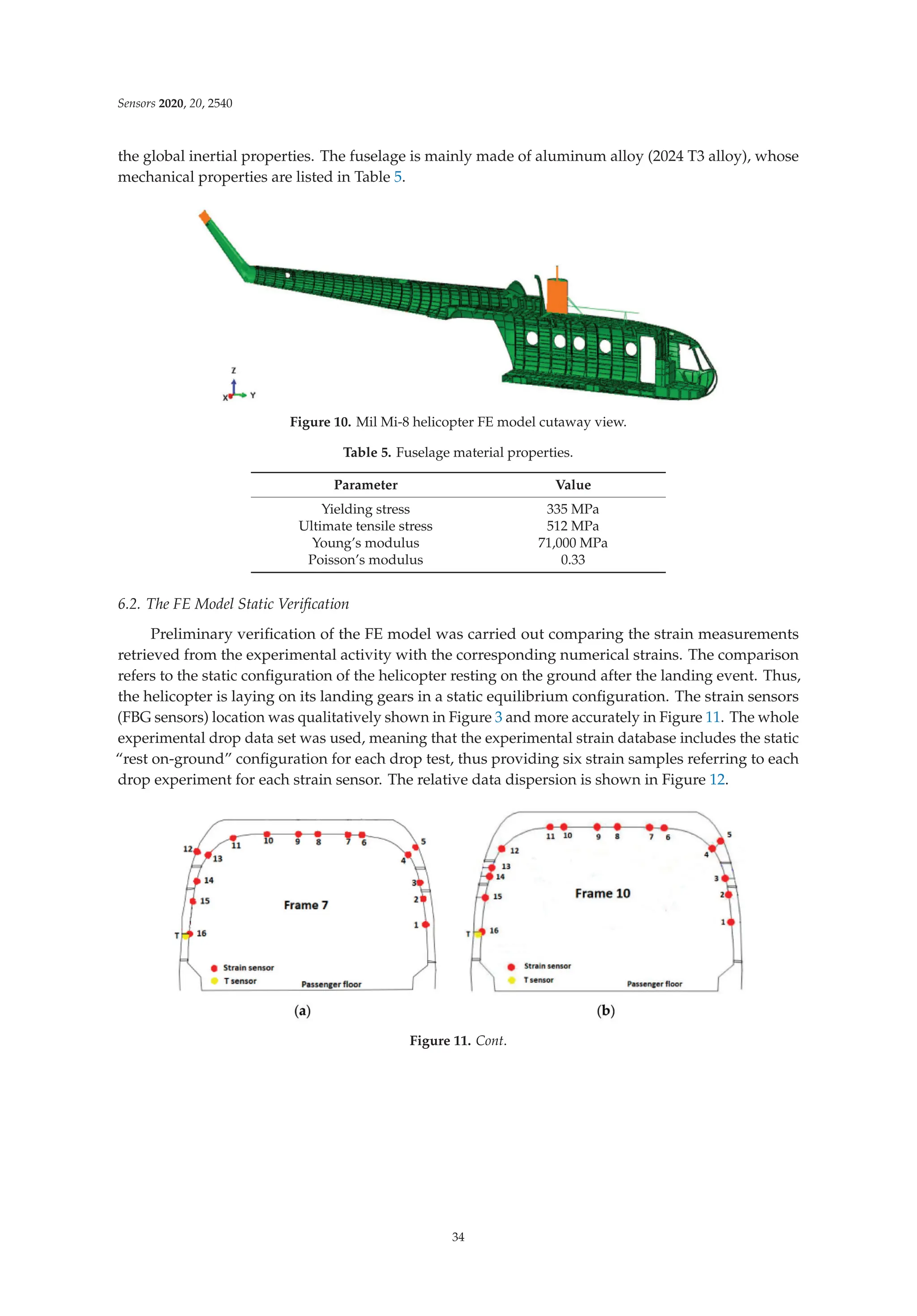
![Sensors 2020, 20, 2540
Figure 11. Sensor location for: (a) frame 7, (b) frame 10 and (c) tail boom.
Figure 12. Experimental (EXP) vs. finite element analysis (FEA) strain comparison for (a) frame 7,
(b) frame 10, and (c) tail boom.
The measured strains were calculated as perturbations with respect to the helicopter in the hung
configuration (prior to the drop); as a result, the measured strain field is null in the hung configuration.
The measured strain tensor can be thus formally defined as:
[εM(t, x)] = [εA(t, x)] − [εH(t, x)] (7)
The strain tensor is generally time and location dependent. As Figure 12 illustrates, frame 7 shows
the best match between the FE analysis outcomes and the experimental results. In contrast, frame
10 seems to be highly sensitive to the environmental noise, having a higher data dispersion. Still,
the experimental data dispersion envelope of frame 10 includes the FE strain values. The tail boom
numerical strains get more accurate as the tail rotor is approached (the tail boom sensor numbering
increases from the tail boom free end to the fuselage connection). In contrast, in the fuselage attachment
zone the bias and the data dispersion are higher. Again, the FE strain values were included in the
experimental envelope.
To objectively comment on the already presented results alone, some considerations about the FE
model have to be pointed out. The finite element model suffers from having a mass distribution that
is not supported by accurate data or measurements. This, in turn, affects the numerically computed
structural response of the rotorcraft, since the mass distribution is crucial in determining the stress
partition on the structure. Furthermore, the real aircraft structure is made up of riveted or bolted
connected subcomponents; however, the FE model fuselage does not display such features. The FE
model fuselage is made as a unique body, and there are no joints of any kind. Thus, the FE model
exhibits an increased structural stiffness with respect to the real riveted structure, which might cause
35](https://image.slidesharecdn.com/25327745-250524183759-d847efeb/75/Fiber-Bragg-Grating-Based-Sensors-And-Systems-Oleg-Morozov-50-2048.jpg)
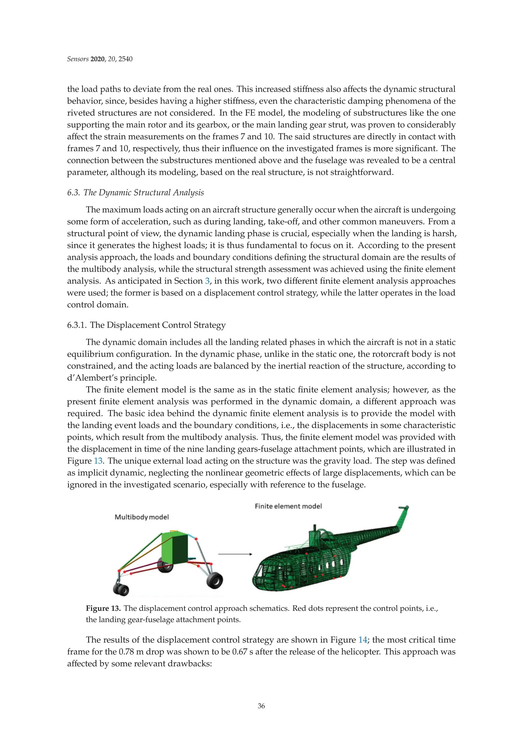
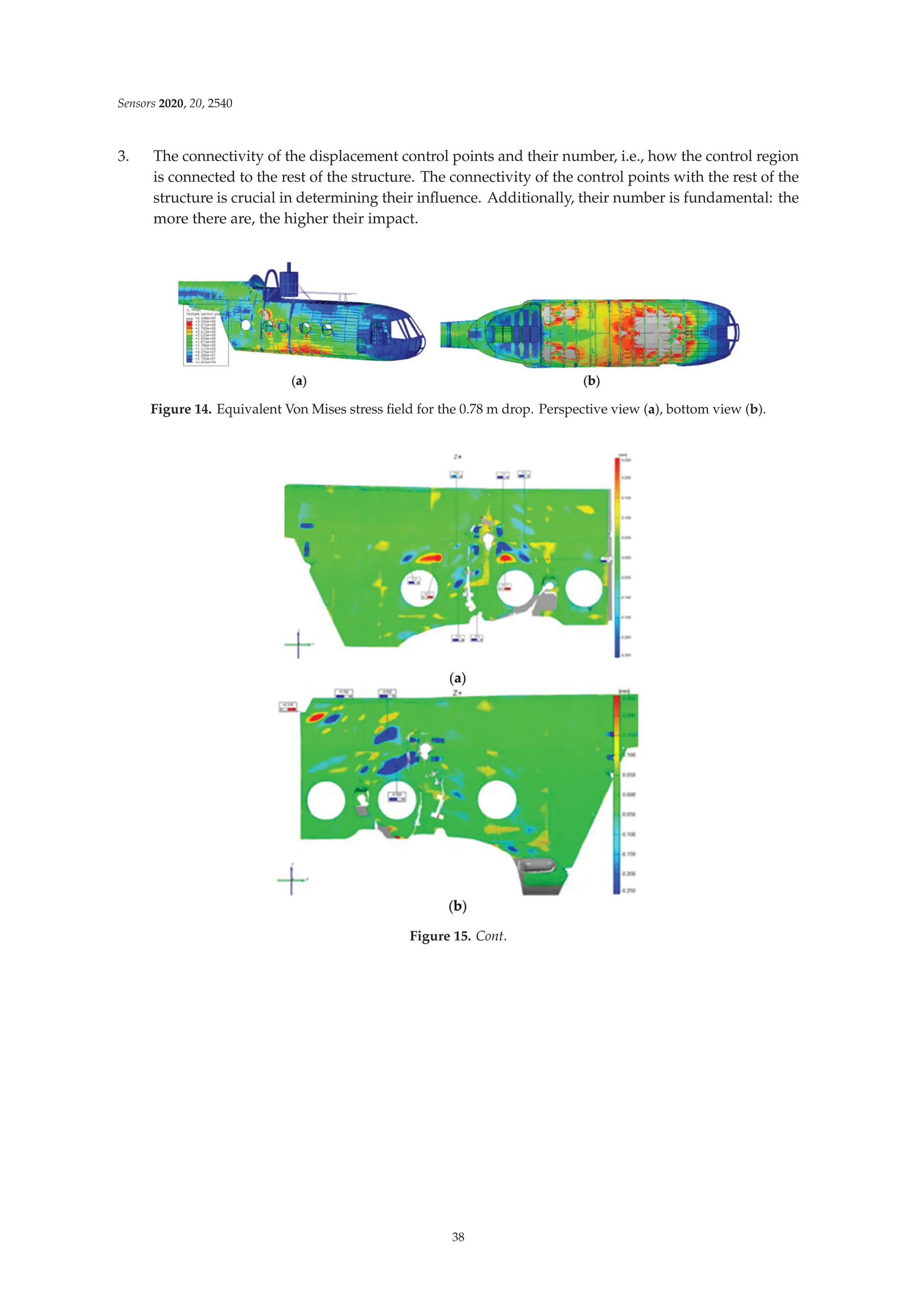
![Sensors 2020, 20, 2540
Figure 15. Optical scans of the fuselage skin after the 0.78 m drop. MLG attachment zone, right (a) and
left (b); tail boom-fuselage connection (c).
Figure 16. Experimental (EXP) vs. FEA strain comparison for (a) frame 7, (b) frame 10, and (c) tail boom.
6.3.2. The Inertia Relief Method
Aiming at providing an alternative analysis approach to the displacement control strategy,
the inertia relief method (which is supported by Abaqus CAE) was applied to the landing problem.
This method enables the analysis of the rotorcraft structure without the need to perform a dynamic
analysis, thus permitting the examination of unsupported structures as if they were in a static
equilibrium condition, as described in Section 3. Consequently, the inertia relief analysis is not
time-dependent, but it investigates a single time instant. The loads are enforced to the landing
gear-fuselage attachment points, i.e., the same control points used in the displacement control strategy
(Figure 13). In the present analysis, the loads were selected from the multibody analysis load time
history, aiming at analyzing the structure under the most critical conditions, which are likely to belong
to the time window immediately following the ground impact, namely when the sum of the elastic
and damping forces related to the shock absorber is at its highest. Another valuable information
which has to be provided to the model is the rotorcraft attitude corresponding to the investigated
time history instant. The structure attitude is fundamental, since the aircraft is inserted into the
gravitational field, and the direction of the same with respect to the structure coordinate directions
is essential. The rotorcraft attitude is controlled by the gravity load vector, whose components are
adjusted depending on the required attitude. As stated in Section 3, to obtain accurate inertia relief
analyses, the periods of the applied loads should be much greater than the periods of the rigid body
modes restrained [40], so that the dynamic structural effects can be legitimately neglected. Inertia relief
analysis does not account for the structure dynamic response. Depending on the structure and on the
spectrum of the applied loads, the stress/strain contribution related to the structure dynamics might be
relevant. Thus, the inertia relief analysis has to be applied cautiously. Here, the analysis was focused
on the first instants after the ground impact (i.e., when the main landing gear loads on the structure
reach their maximum value); thus, the low frequency-high displacements (i.e., high strain/stresses)
contribution on the fuselage was expected not to be yet settled, while the contribution due to the elastic
39](https://image.slidesharecdn.com/25327745-250524183759-d847efeb/75/Fiber-Bragg-Grating-Based-Sensors-And-Systems-Oleg-Morozov-54-2048.jpg)


![This ebook is for the use of anyone anywhere in the United
States and most other parts of the world at no cost and with
almost no restrictions whatsoever. You may copy it, give it away
or re-use it under the terms of the Project Gutenberg License
included with this ebook or online at www.gutenberg.org. If you
are not located in the United States, you will have to check the
laws of the country where you are located before using this
eBook.
Title: Critical, Historical, and Miscellaneous Essays; Vol. 2
Author: Baron Thomas Babington Macaulay Macaulay
Editor: Edwin Percy Whipple
Release date: November 6, 2017 [eBook #55902]
Most recently updated: October 23, 2024
Language: English
Credits: Produced by David Widger from page images
generously
provided by the Internet Archive
*** START OF THE PROJECT GUTENBERG EBOOK CRITICAL,
HISTORICAL, AND MISCELLANEOUS ESSAYS; VOL. 2 ***](https://image.slidesharecdn.com/25327745-250524183759-d847efeb/75/Fiber-Bragg-Grating-Based-Sensors-And-Systems-Oleg-Morozov-60-2048.jpg)