Investigation of a Partially Loaded Resonant Cavity_Zeller_Kraft
E. Flaws in the Resonant Cylinder and the Associated Design Iterations
1. Flaws in the Resonant Cylinder and the Associated
Design Iterations
California Polytechnic State University, San Luis Obispo
Aerospace Engineering Department
By: Brian Kraft and Kurt Zeller
After completing the manufacturing phase of the experiment we attempted to connect the
cylindrical cavity to our pendulum and execute test runs. This proved to be a more complex issue
then initially thought and an educational experience in waveguide manufacturing and operations.
Unfortunately, it proved to be extremely difficult to provide power to our cavity without inducing
arcing at one or more of the metal interfaces. Grounding different components of the cavity became
a primary focus, resulting in a number of new designs. The different configurations and the
motivation behind each one will be described in this document.
I. Introduction
Understanding arcing and the potential sources of arcing was the first step in mitigating this complex
issue. Research proved that arcing within waveguides is greatly based upon the frequency and power of
the source that is used. Working at 2.45 GHz meant that our signal had a wavelength of about 12 cm,
therefore any perturbations in geometry on the order of a cm had a significant impact on the propagation
of electromagnetic waves. This trend becomes even more exaggerated as higher frequencies. Although
this is an important consideration it was likely the high power magnetron which induced the majority of
our arcing. Small gaps between components on the order of millmeters proved to be an issue when high
power was used. These small gaps prevented uniform charging of adjacent metallic components which
inevitably led to arcing at multiple points throughout the cylinder. As the cylinder design evolved, these
changes were centralized around the sliding metal end plate and the connection between the waveguide
adapter and the cylinder.
II. Location of Arcing
After each test run was conducted the cylindrical cavity was opened to observe the location of
arcing. The high power that was used made this a fairly simple task and arcing could typically be located
within a minute of decomposing the cavity to its individual parts. The first source of arcing observed in
this experiment occurred between the nylon screws that were used to mount the movable plate and the
walls of the interior of the cavity. After conducting longer tests runs, it was observed that the energy
would be dissipated through the nylon screws to the metal plate located at the backend of the movable
plate. These longer duration runs resulted in partial melting of the screws and forced a new design or
different materials for attaching the HDPE section to the movable plate. In hindsight, using nylon screws
was poor decision because nylon is a polar material and therefore experiences intense heating when
bombarded with high amount of microwave power. The specific changes in design that resulted will be
discussed in the following section.
Another source of arcing was between the edges of the movable plate and the inner surfaces of the
cylindrical cavity. Small black singes were observed within the cavity and corresponded with marks
2. around the diameter of the movable plate or the screw used to fix the movable plate to the shaft forming
the plunger. This led to design iterations that attempted to uniformly ground the movable plate to the
walls of the cavity and different diameter plates for a smaller contact distance. Throughout the experiment
arcing was also observed between the connection of the microwave waveguide adapter to the cylindrical
cavity. The microwave waveguide was removed from one the same microwave that the magnetron was
obtained from and therefore was matched well with that component. In order to remove this waveguide a
band saw was used to cut through the thick metal surfaces obtain the waveguide independent of excess
metal. Operation of the saw resulted in a small, wavelike edge due to the compression and shearing
involved in this cut. Attaching this heterogeneous surface to the flat surface of the end of the cylinder
resulted in asymmetric grounding and small gaps where arcing was observed. Furthermore, it was later
discovered that a nonconducting layer of paint had been applied to the surface of the waveguide during
manufacturing. Eliminating arcing became the greatest setback in this project and many weeks were spent
attempting to fix this issue. These attempts are outlined with great detail in the following section.
III. Design Iterations
In order to prevent arcing to the nylon screws either new screws had to be used or a different end
plate needed to be manufactured. New screws were briefly considered but it was determined that
manufacturing screws entirely of HDPE was not worth the time or raw materials. One brief design
iteration involved countersinking the nylon screws halfway through the HDPE plate and placing small
HDPE plugs overtop of the countersunk areas. The logic behind this design was that arcing might be less
likely to occur to the screws if the electromagnetic wave front met a uniform section of HDPE rather than
a plate of HDPE with two protruding screw heads. Unfortunately this did not mitigate the issue and the
screws continued to be arced to resulting in rapid heating. Therefore a new methodology need to be
devised for fastening the HDPE plate to the plunger without the use of any type of screw. This resulted in
the manufacturing of a press fit plunger where a piece of HDPE could simply be pressed into the metal
plunger. Metal screws were used to attach the metal press fit component to the backend of the movable
plunger. These screws were countersunk within the plate so the electromagnetic waves would travel
through a uniform HDPE surface before hitting a uniform aluminum surface. The edges of the press fit
plate were angled slightly inward to allow a strong grip on the piece of HDPE that was used. This
solution effectively eliminated arcing to the surface of our dielectric (the HDPE).
Prior to implementing the pressfit plate a number of different plates were used to provide a
conductive interface between the interior of the cylinder and the movable plunger. One technique
involved fastening two grounding wires along the screws of the movable plate and connecting them to the
bracketry required to hold the plunger. After this solution failed aluminum foil was wrapped along the
diameter of the plate in hopes that it would compress as needed to provide flush contact to the interior of
the cylinder. A third solution involved machining a closer diameter aluminum plate which contacted the
interior surface at a number of different points. The asymmetric contact proved to be an issue and once
more this design failed. The final attempt made to improve the movable plunger involved cutting out a
number of circles of copper mesh that could be fastened to the movable plate using the two mounting
screws. This mesh protruded beyond the diameter of the plunger slid along the edges of the interior as the
piece moved.
Eliminating arcing between the waveguide and the cylinder required several different designs. After
discovering the tell tales black singes, the edges of the waveguide were hammered and trimmed properly
allow a more uniform contact area. Although this method did not succeed through the process of
tampering with the waveguide it was learned that the exterior surface paint was nonconductive. A grinder
was then used to remove this paint but unfortunately arcing persisted. The next idea that was implemented
was purchasing Ox-Gard and smothering the edge of the cylinder with this conductive putty. Ox-Gard
proved to be extremely messy and although it reduced the perceived severity of the arcing it did not
entirely eliminate this issue. Eventually a very fine copper mesh was purchased and layered appropriately
3. along the exterior of the cylinder. When the waveguide was fastened to this interface the copper sheets
would compress allowing full contact along the surface (although the degree of compression along the
diameter was not consistent).
IV. Conclusion and Final Design Considerations
Although many of these ideas seemed promising at the time they all eventually failed to prevent
arching. At this point in time it is difficult to determine what the true issue is that is causing arcing. Many
of these design iterations prevented arcing at a specific spot but failed to prevent this phenomenon as a
whole. The severity of arcing has been drastically reduced with the implementation of each new design
but it cannot be entirely eliminated. After a small initial arc the cavity does not continue to arc or arc
again throughout the course of an approximately 20 second test run.
Rather than continuing to fight this issue a decision was made to delay testing until the truncated cone
was depleted. Had the team been motivated to continue pursuing this geometry there are a number of
changes that could be made which reflect the knowledge gained through experimentation. The most
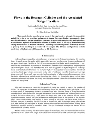
obvious change that would be made is the implementation of an electromagnetic choke. This devices
would have required a number of different layers or a complexly machined part to implement.
Figure ____ shows an example of an electromagnetic choke. Because the mode seen in our cylinder is
circular, the slots shown in the figure would need to extend along the entire circumference of the plate.
These slots allow any electromagnetic energy that might be escaping from the cavity to be absorbed
therefore preventing a buildup of surface current.
An additional change that could have been made is the design of a specific waveguide for input to the
cylinder. EMPro could have been utilized prior to building the waveguide to determine the functionality
of this component with our source. After constructing this piece, it could then be brought to the VNA to
ensure it is well matched with an actual magnetron antenna. This same methodology could be applied to
the cylindrical cavity that was used in this experiment. The cavity was constructed prior to determining
how to use EMPro therefore it was not based off a specific simulated result. Only the theoretical formulas
were used to determine the appropriate dimensions of the cavity. The combination of these two designs
would likely allowed for higher quality resonances and the propagation of TE modes rather than TM
modes which are theorized to be better for thrust production.
Although there are a number of ideas that could be implemented, this project is severely limited by
budget considerations and manufacturing. If these waveguides and components could be purchased from
companies such as Gurling Electronics one could assure that arcing would not occur and the signal would
have very low reflectance. These off the shelf waveguides are extruded and often designed to customer
specifications therefore making them extremely expensive pieces of equipment. A simple rectangular
waveguide costs close $1000 which was beyond the scope of the budget for this project. On the other
hand manufacturing these components would require large amounts of raw aluminum or copper which
4. ultimately would be very expensive. Even after purchasing this material there is still a likelihood that
arcing could occur due to the precision of the CNCs we have available on campus. There are CNCs that
can machine with nanometer precision which would ideal for microwave applications. After speaking
with our industry expert, John Gurling, it became clear that microwave engineering is a great deal of
guess and check. Even after a design has been produced it must still be tested with high power or high
frequency electronics and occasionally these parts do night align properly. Most microwave systems
feature tunable components to absorb reflected power or ensure resonance at specific frequencies. The
evolution of the plunger described earlier in this experiment proved how difficult these tunable
components can be without the proper manufacturing capabilities. John described microwave engineering
as a field that involves a bit of “black magic” and sadly, we are not magicians.