Download to read offline

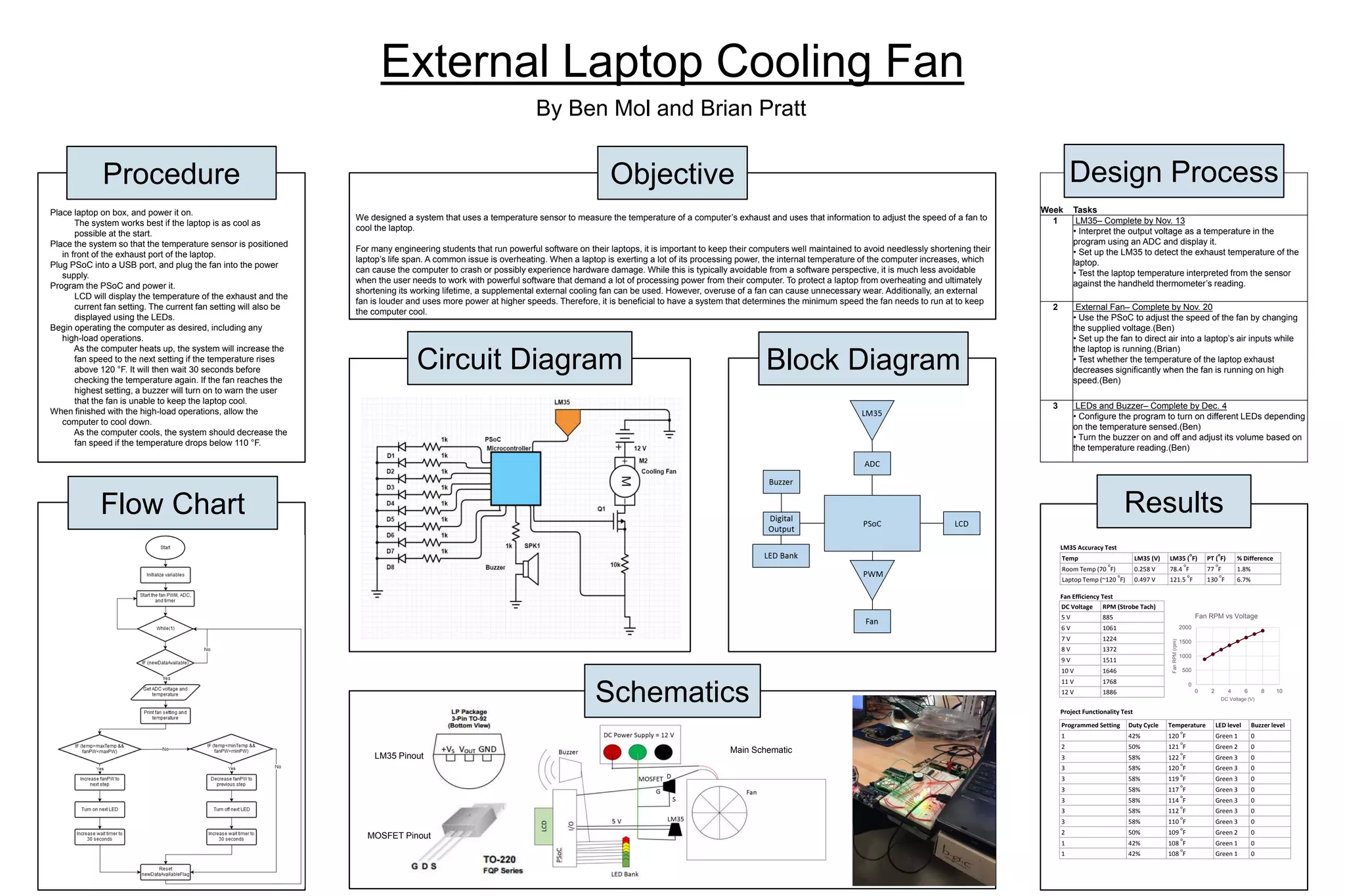

The document outlines a project focused on designing a temperature-controlled external cooling fan system for laptops using an LM35 temperature sensor and a PSoC to manage fan speed and temperature readings. Tasks are scheduled for completion, including setting up the sensor, testing fan efficiency, and configuring output indicators like LEDs and a buzzer based on temperature thresholds. The goal is to mitigate overheating in laptops during high-load operations by adjusting fan speed intelligently to prolong the device's lifespan.


![Tamperature controlled fan_project_report[1]](https://cdn.slidesharecdn.com/ss_thumbnails/tamperaturecontrolledfanprojectreport1-170912121052-thumbnail.jpg?width=640&height=640&fit=bounds)


