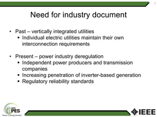
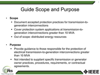
Exploring IEEE C37.246-2017
Guide for Protection Systems
of Transmission-to-Generation
Interconnections
Presented by Abu Bapary
American Electric Power
Tulsa, OK
1
Objectives
• Need for industry document
• Scope/purpose of new guide
• Guide contents
• Summary
2
Need for industry document
• Past – vertically integrated utilities
 Individual electric utilities maintain their own
interconnection requirements
• Present – power industry deregulation
 Independent power producers and transmission
companies
 Increasing penetration of inverter-based generation
 Regulatory reliability standards
3
Guide Scope and Purpose
• Scope
 Document accepted protection practices for transmission-to-
generation interconnections
 Cover protection system applications at transmission-to-
generation interconnections greater than 10 MVA
 Out of scope: distributed energy resources
• Purpose
 Provide guidance to those responsible for the protection of
electrical transmission-to-generation interconnections greater
than 10 MVA
 Not intended to supplant specific transmission or generator
owner practices, procedures, requirements, or contractual
agreements.
4
Guide contents
Establishing interconnection
• Technical data exchange between transmission and generator
owners
Interconnection configurations
• Straight bus
• Dual-terminal bus
• Tapped connections
System studies
• Evaluate proposed transmission-to-generation interconnections
• Power flow, transient stability, short-circuit, and relay
coordination
5
Guide contents (cont.)
Protection system settings for interconnections
• Specific protection system guidelines to be considered when
designing new or upgrading existing interconnection substation.
• Interconnection substation protection and control functions
• Issues of autoreclosing near generation and interconnection
communication-based transfer tripping
• Tapped connections
• Interconnections with renewable energy sources
6
Establishing interconnection
Role of transmission owner
• Selects relays and protection schemes
• Determines maximum and minimum fault current levels
• Approves generator step-up (GSU) or interconnection
transformer winding configurations
• Provides data on:
• Power system stability
• Synchronizing practices
• Autoreclosing practices
• Grounding coordination
7
Establishing interconnection
Role of generator owner
• Proposes point of interconnection
• Provides design drawings
• Provides data on:
• Generator
• Transformer
• Ride-through capability
• Reactive power, frequency control
• Short circuit levels
8
Establishing interconnection
Specific considerations
• Various items to agree on:
• Equipment
• Protection
• Testing
• Voltage transient effect
9
Interconnection configurations
Tie line
10
Transmission
Station
Generating Unit
Transmission
Station
Generating Unit
a) Double breaker
arrangement
b) Single breaker
arrangement
Interconnection configurations
Switching station
11
Switching
Station
Transmission
Line
Generating Unit
Transmission
Station A
Transmission
Station B
Interconnection configurations
Tapped connection
12
Transmission
Line Tap
Generating Unit
Transmission
Station A
Transmission
Station B
System studies
• System impact study
• Facilities study
• Specific system studies
• AC power flow analysis
• Transient stability analysis
• Short circuit analysis
• Relay coordination studies
• Subsynchronous resonance (SSR) studies
13
Interconnection protection functions
Synch Check (25)
14
25
Transmission
Network
52
Close
25
52 Close
Coil
(+)
(-)
Interconnection protection functions
Degraded Grid Voltage (27)
• Generator auxiliary systems
• Specified limits
• Separation
• Multiple elements
• Coordination
• See guide for further details
15
Interconnection protection functions
Reverse Power (32) – generator motoring
• Typically, part of generator protection
• Applied with loss of prime mover energy
• Trip 52G for power flow into the generator
16
32
Transmission
Network
52M
52G
Interconnection protection functions
Reverse Power (32) – one way
• Industrial plant with local generation
• Generation for load offset, no energy export
• Lost network source, power flowing into network
• Trip 52M
• Trip 52G
17
32
Transmission
Network
52M
52G
Load
Interconnection protection functions
Breaker failure protection (50BF)
18
Transmission Line
Generating
Unit
50
BF
REM
BU
Interconnection protection functions
GSU Ground Overcurrent (51TG)
19
Example in
the Guide!
Transmission Line
Generating
Unit
51
TG
67N
Interconnection protection functions
Frequency protection (81)
• Typically applied at generation
• Anti-islanding protection
• Manufacturer recommendations
• Regional requirements
• Backup
20
Interconnection protection functions
Bus Differential Protection (87B)
• When is interconnection a bus?
• IEEE Std C37.234 - Protective Relay
Applications to Power System Buses.
21
Interconnection protection functions
Tie line current differential protection (87L)
• When is interconnection a line?
• Current differential scheme
• Not affected by weak infeed conditions
• Only requires line currents
• Setting simplicity
22
Line autoreclosing
• Intermittent faults
• Consider possible damage to generation
• Mitigating options
23
Tapped connections
Design issues
• Tap adds exposure for line faults to the existing circuit
• Loss of the transmission line results in a loss of generator
24
Transmission
Line Tap
Generating Unit
Transmission
Station A
Transmission
Station B
Tapped connections
Protection issues
• More complex multi-terminal protection schemes
• May require communication assisted schemes
• Relay coordination issues
• Zone 1 distance protection
• Infeed effects
25
Renewable energy resources
Wind plants
• Fault current contribution
• Varying fault currents
• Protection basics
26
Renewable energy resources
Solar PV inverters
• Current controlled devices
• Fault currents
• Time delayed elements
• Filtering components of the inverter
• Protection basics
27
Summary
28
• Engineering transmission-to-generation interconnection
• Design reliable interconnection for dependable
system operation during normal or abnormal system
conditions.
• Collaborate between transmission and generator
owners during interconnection design
• Role of IEEE C37.246 guide
• Developed to aid protection engineers in
interconnection design
• Documents and explains protection principles and
best practices
• Expounds on practical application issues

Exploring IEEE-C37.246-2017 Guide -Presenatation.pdf

  • 1.
    Exploring IEEE C37.246-2017 Guidefor Protection Systems of Transmission-to-Generation Interconnections Presented by Abu Bapary American Electric Power Tulsa, OK 1
  • 2.
    Objectives • Need forindustry document • Scope/purpose of new guide • Guide contents • Summary 2
  • 3.
    Need for industrydocument • Past – vertically integrated utilities  Individual electric utilities maintain their own interconnection requirements • Present – power industry deregulation  Independent power producers and transmission companies  Increasing penetration of inverter-based generation  Regulatory reliability standards 3
  • 4.
    Guide Scope andPurpose • Scope  Document accepted protection practices for transmission-to- generation interconnections  Cover protection system applications at transmission-to- generation interconnections greater than 10 MVA  Out of scope: distributed energy resources • Purpose  Provide guidance to those responsible for the protection of electrical transmission-to-generation interconnections greater than 10 MVA  Not intended to supplant specific transmission or generator owner practices, procedures, requirements, or contractual agreements. 4
  • 5.
    Guide contents Establishing interconnection •Technical data exchange between transmission and generator owners Interconnection configurations • Straight bus • Dual-terminal bus • Tapped connections System studies • Evaluate proposed transmission-to-generation interconnections • Power flow, transient stability, short-circuit, and relay coordination 5
  • 6.
    Guide contents (cont.) Protectionsystem settings for interconnections • Specific protection system guidelines to be considered when designing new or upgrading existing interconnection substation. • Interconnection substation protection and control functions • Issues of autoreclosing near generation and interconnection communication-based transfer tripping • Tapped connections • Interconnections with renewable energy sources 6
  • 7.
    Establishing interconnection Role oftransmission owner • Selects relays and protection schemes • Determines maximum and minimum fault current levels • Approves generator step-up (GSU) or interconnection transformer winding configurations • Provides data on: • Power system stability • Synchronizing practices • Autoreclosing practices • Grounding coordination 7
  • 8.
    Establishing interconnection Role ofgenerator owner • Proposes point of interconnection • Provides design drawings • Provides data on: • Generator • Transformer • Ride-through capability • Reactive power, frequency control • Short circuit levels 8
  • 9.
    Establishing interconnection Specific considerations •Various items to agree on: • Equipment • Protection • Testing • Voltage transient effect 9
  • 10.
    Interconnection configurations Tie line 10 Transmission Station GeneratingUnit Transmission Station Generating Unit a) Double breaker arrangement b) Single breaker arrangement
  • 11.
  • 12.
    Interconnection configurations Tapped connection 12 Transmission LineTap Generating Unit Transmission Station A Transmission Station B
  • 13.
    System studies • Systemimpact study • Facilities study • Specific system studies • AC power flow analysis • Transient stability analysis • Short circuit analysis • Relay coordination studies • Subsynchronous resonance (SSR) studies 13
  • 14.
    Interconnection protection functions SynchCheck (25) 14 25 Transmission Network 52 Close 25 52 Close Coil (+) (-)
  • 15.
    Interconnection protection functions DegradedGrid Voltage (27) • Generator auxiliary systems • Specified limits • Separation • Multiple elements • Coordination • See guide for further details 15
  • 16.
    Interconnection protection functions ReversePower (32) – generator motoring • Typically, part of generator protection • Applied with loss of prime mover energy • Trip 52G for power flow into the generator 16 32 Transmission Network 52M 52G
  • 17.
    Interconnection protection functions ReversePower (32) – one way • Industrial plant with local generation • Generation for load offset, no energy export • Lost network source, power flowing into network • Trip 52M • Trip 52G 17 32 Transmission Network 52M 52G Load
  • 18.
    Interconnection protection functions Breakerfailure protection (50BF) 18 Transmission Line Generating Unit 50 BF REM BU
  • 19.
    Interconnection protection functions GSUGround Overcurrent (51TG) 19 Example in the Guide! Transmission Line Generating Unit 51 TG 67N
  • 20.
    Interconnection protection functions Frequencyprotection (81) • Typically applied at generation • Anti-islanding protection • Manufacturer recommendations • Regional requirements • Backup 20
  • 21.
    Interconnection protection functions BusDifferential Protection (87B) • When is interconnection a bus? • IEEE Std C37.234 - Protective Relay Applications to Power System Buses. 21
  • 22.
    Interconnection protection functions Tieline current differential protection (87L) • When is interconnection a line? • Current differential scheme • Not affected by weak infeed conditions • Only requires line currents • Setting simplicity 22
  • 23.
    Line autoreclosing • Intermittentfaults • Consider possible damage to generation • Mitigating options 23
  • 24.
    Tapped connections Design issues •Tap adds exposure for line faults to the existing circuit • Loss of the transmission line results in a loss of generator 24 Transmission Line Tap Generating Unit Transmission Station A Transmission Station B
  • 25.
    Tapped connections Protection issues •More complex multi-terminal protection schemes • May require communication assisted schemes • Relay coordination issues • Zone 1 distance protection • Infeed effects 25
  • 26.
    Renewable energy resources Windplants • Fault current contribution • Varying fault currents • Protection basics 26
  • 27.
    Renewable energy resources SolarPV inverters • Current controlled devices • Fault currents • Time delayed elements • Filtering components of the inverter • Protection basics 27
  • 28.
    Summary 28 • Engineering transmission-to-generationinterconnection • Design reliable interconnection for dependable system operation during normal or abnormal system conditions. • Collaborate between transmission and generator owners during interconnection design • Role of IEEE C37.246 guide • Developed to aid protection engineers in interconnection design • Documents and explains protection principles and best practices • Expounds on practical application issues