Download to read offline
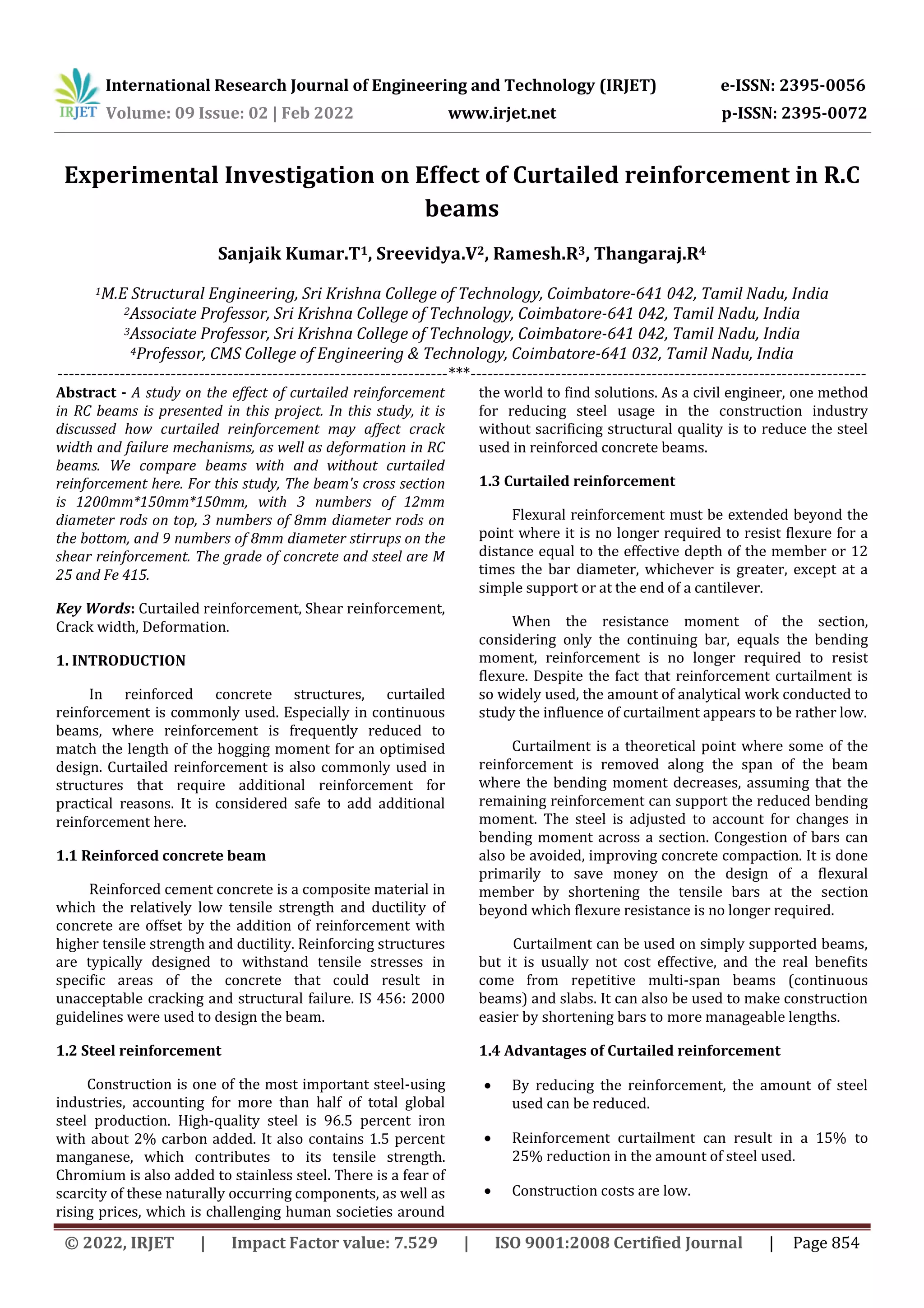
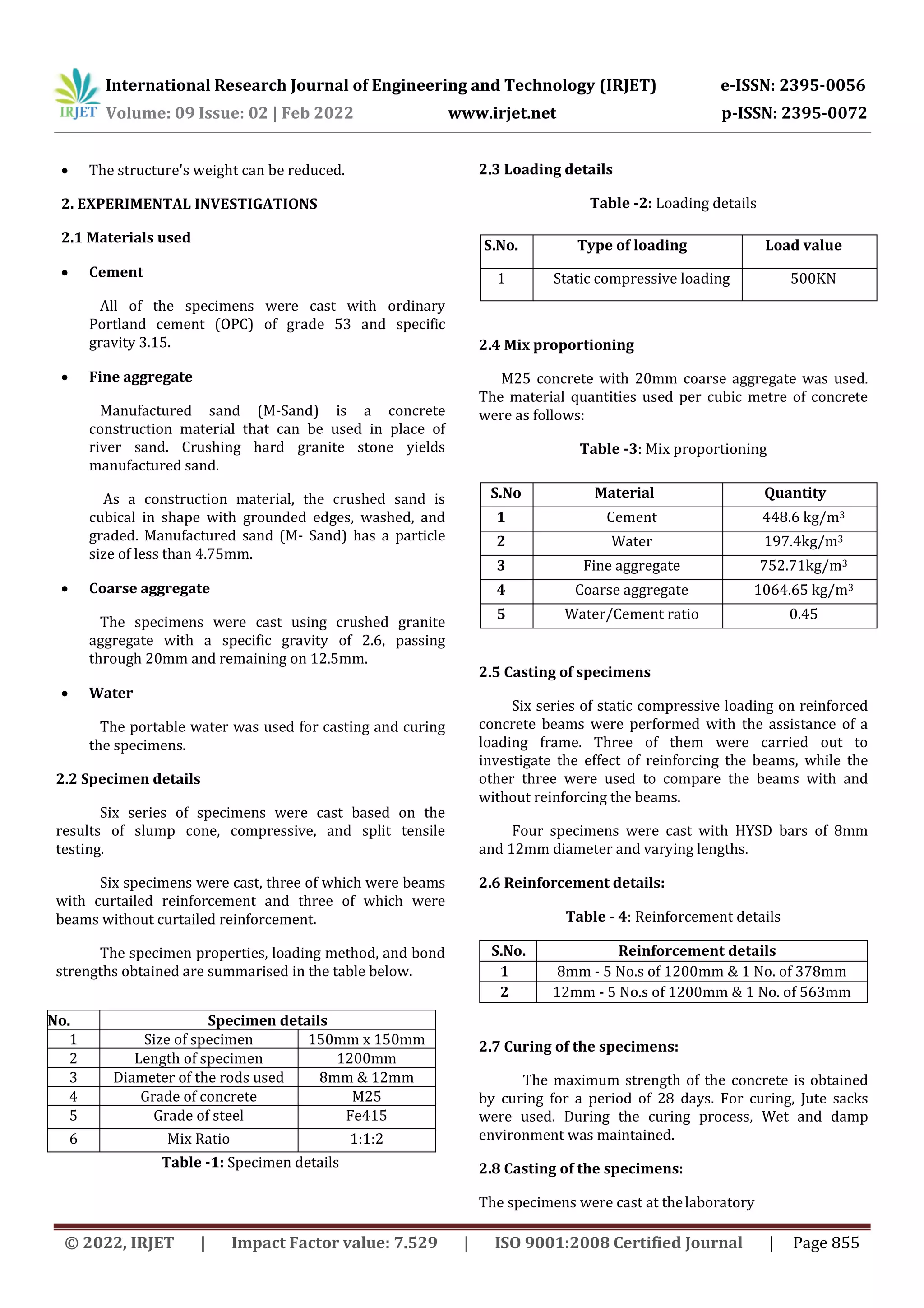
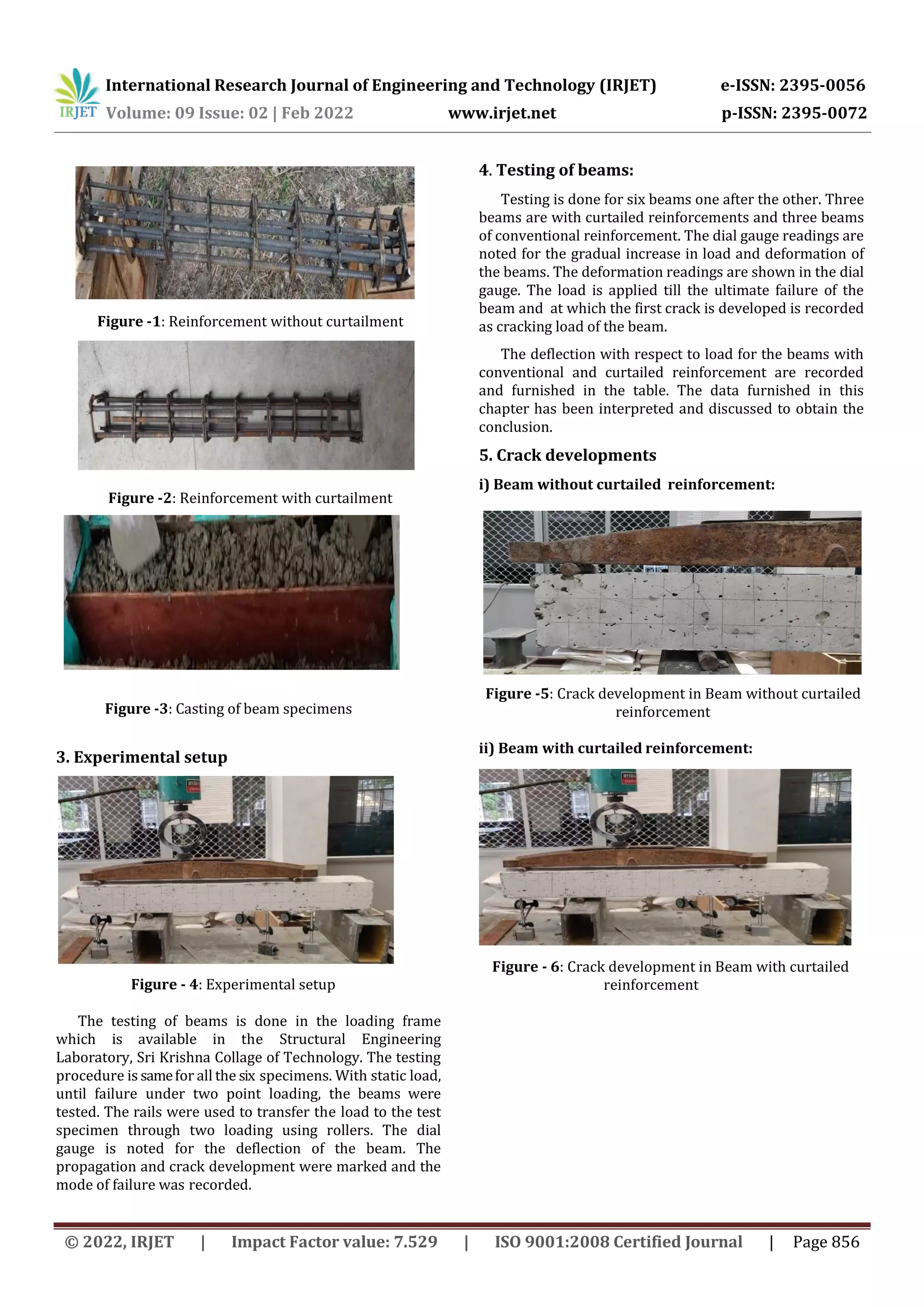
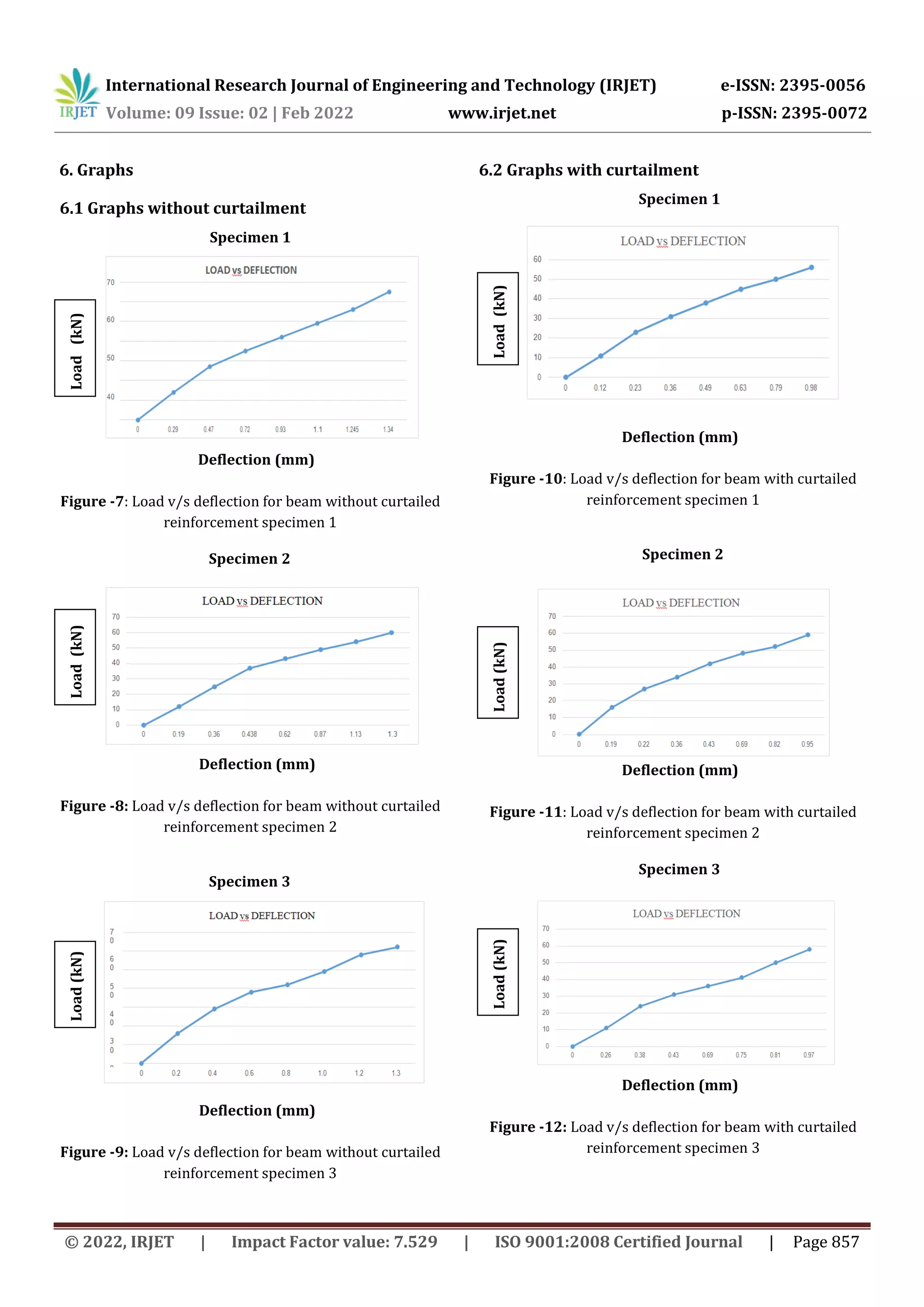

The document experimentally investigates the effect of curtailed reinforcement in reinforced concrete beams. Six beams were cast - three with curtailed reinforcement and three without. The beams were subjected to static compressive loading. Beams with curtailed reinforcement showed similar deflection levels to those without curtailment, while using 10.65% less steel. Cracks developed earlier in beams with curtailed reinforcement, but failure modes were similar between beam types. In conclusion, curtailed reinforcement can reduce steel usage without compromising structural performance, providing a more cost-effective design.


