Download as PDF, PPTX

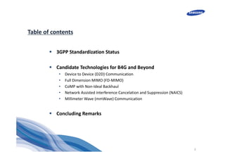

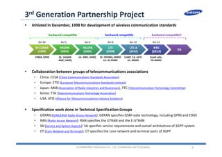
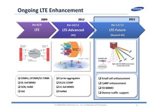
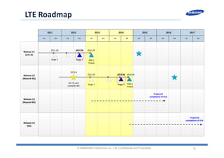

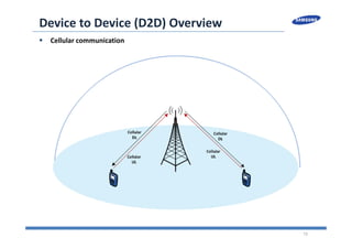


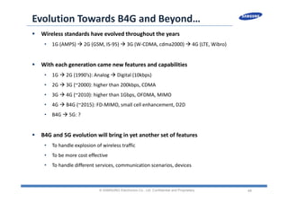

The document discusses the evolution of LTE (Long-Term Evolution) towards beyond 4G (B4G) and 5G, highlighting the standardization efforts by 3GPP and listing candidate technologies like Device-to-Device communication, Full Dimension MIMO, and Network Assisted Interference Cancellation. It outlines the specifications, enhancements, and technology advancements that contribute to the next generation of wireless communication networks. Various industry participants and their roles in developing these technologies are also detailed.