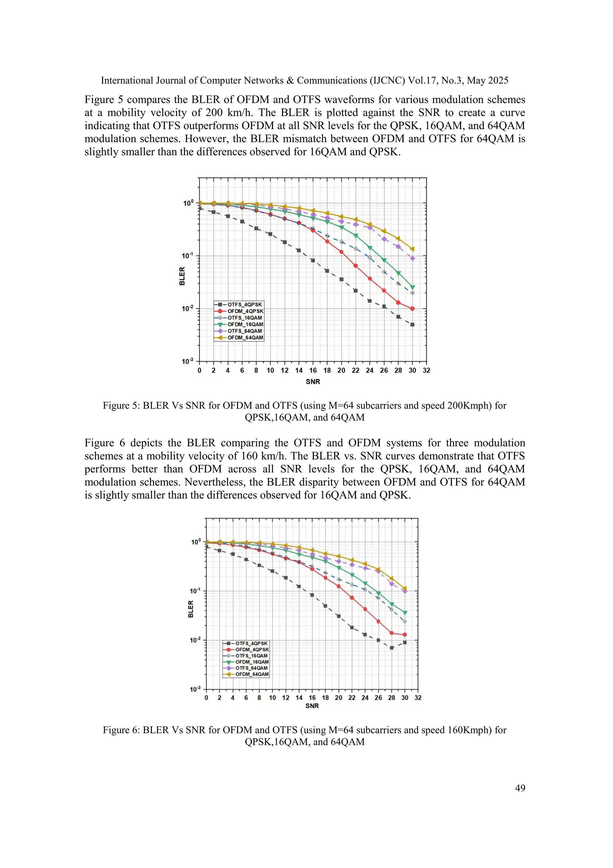
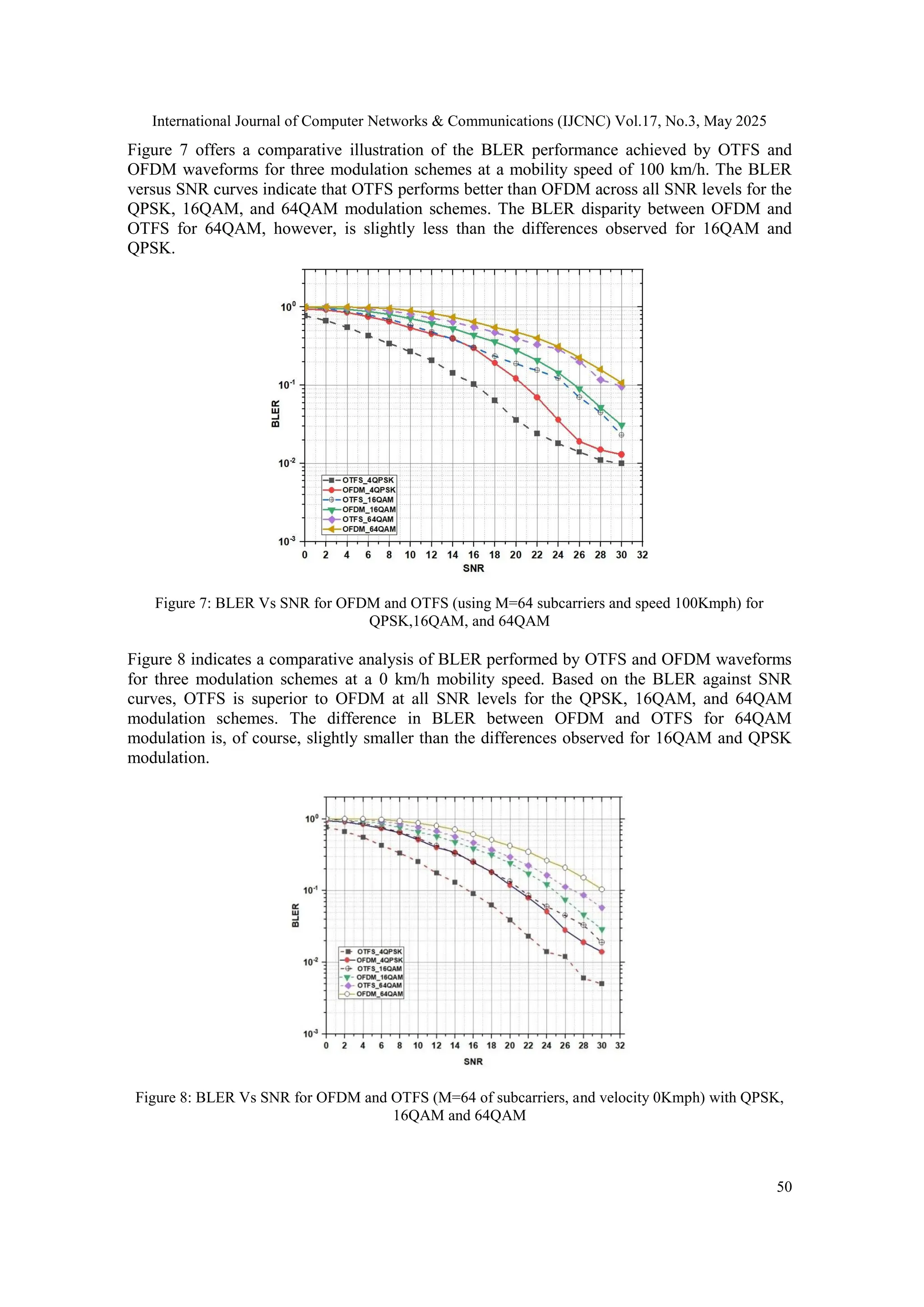
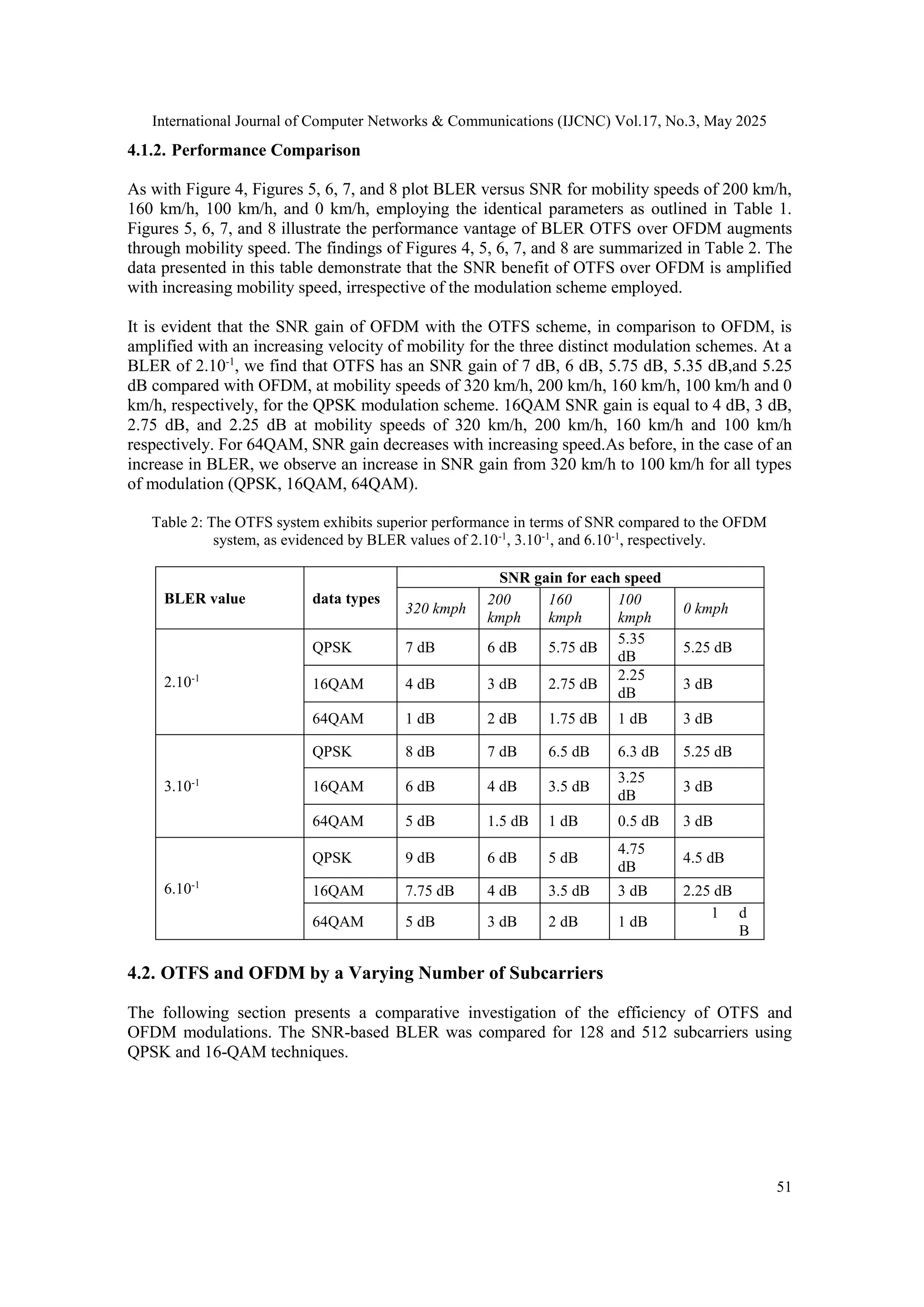
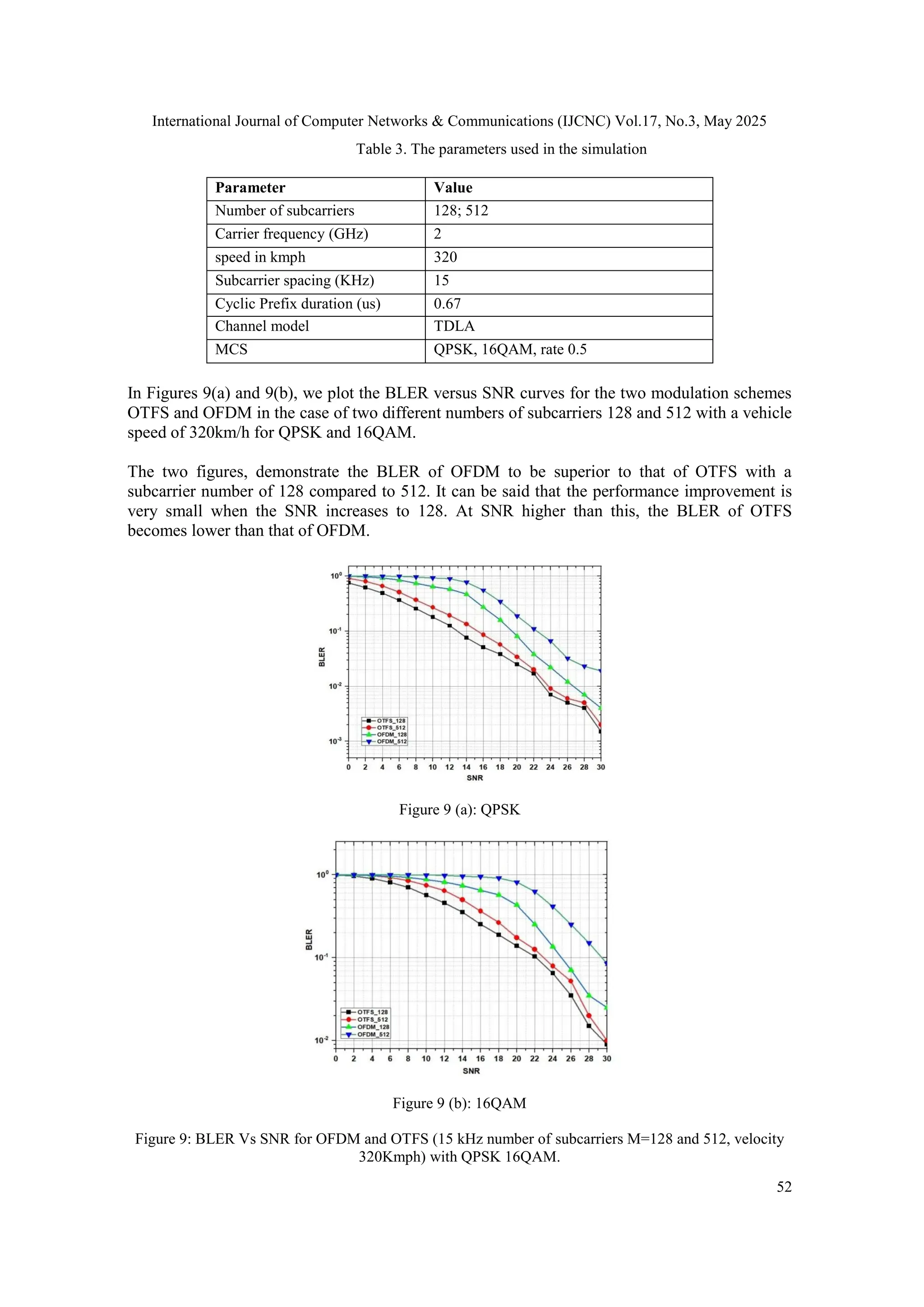
Orthogonal Time-frequency-space (OTFS) modulation represents a pioneering advancement tailored to the requirements of prospective sixth-generation (6G) wireless networks. The innovative design effectively addresses the challenges associated with high-frequency dispersion in wireless transmission environments, offering many advantages over traditional modulation schemes such as orthogonal frequency-division multiplexing (OFDM). OTFS stands out due to its capacity to adapt to dynamic wireless channels with high Delay-Doppler (DD) dispersion, a capability that is not present in traditional frameworks. In contrast to conventional approaches, which assume near-channel stability over an OTFS frame, OTFS modulation is well-suited to environments where the input-output relationship may vary over time due to evolving media or environmental conditions. In a comparative analysis with OFDM, OTFS exhibits superior block error rate (BLER) performance compared to the signal-to-noise ratio (SNR) across varying modulation formats, including QPSK, 16QAM, and 64QAM. Numerical simulations demonstrate that OTFS outperforms OFDM in mitigating transmission errors in diverse scenarios by exploring different reception rates for each waveform.
![International Journal of Computer Networks & Communications (IJCNC) Vol.17, No.3, May 2025
DOI: 10.5121/ijcnc.2025.17303 39
EVALUATING OTFS MODULATION FOR 6G:
IMPACT OF HIGH MOBILITY AND
ENVIRONMENTAL NOISE
Abderrahim Mohammadi 1
, Aziz Dkiouak 2
,Mostafa Baghouri 3
, Saad Chakkor 4
,
Ahmed EL Oualkadi 1
and Anass El Mamouni 4
1
Laboratory of Innovative System Engineering ENSA of Tetuan, Abdelmalek Essaadi
University Tetuan, Morocco
2
STIC Laboratory, Faculty of Sciences, Chouaib Doukkali University, El jadida,
Morocco
3
Smart Materials and Artificial intelligence Team, LCCPS, ENSAM of Casablanca,
University of Hassan II, Morocco
4
Laboratory of Information and Communication Technologies (LabTIC) National
School of Applied Sciences of Tangier (ENSATg), Abdelmalek Essaadi University
Tetuan, Morocco
ABSTRACT
Orthogonal Time-frequency-space (OTFS) modulation represents a pioneering advancement tailored to
the requirements of prospective sixth-generation (6G) wireless networks. The innovative design effectively
addresses the challenges associated with high-frequency dispersion in wireless transmission
environments, offering many advantages over traditional modulation schemes such as orthogonal
frequency-division multiplexing (OFDM). OTFS stands out due to its capacity to adapt to dynamic
wireless channels with high Delay-Doppler (DD) dispersion, a capability that is not present in traditional
frameworks. In contrast to conventional approaches, which assume near-channel stability over an OTFS
frame, OTFS modulation is well-suited to environments where the input-output relationship may vary over
time due to evolving media or environmental conditions. In a comparative analysis with OFDM, OTFS
exhibits superior block error rate (BLER) performance compared to the signal-to-noise ratio (SNR) across
varying modulation formats, including QPSK, 16QAM, and 64QAM. Numerical simulations demonstrate
that OTFS outperforms OFDM in mitigating transmission errors in diverse scenarios by exploring
different reception rates for each waveform.
KEYWORDS
6G, DD, OTFS, OFDM, BLER, SNR.
1. INTRODUCTION
Over the past ten years, networks have transmitted exabytes of data, fueled by advancements in
autonomous vehicles, extensive sensor networks, the Internet of Things (IoT), and the early
development of immersive media. This has resulted in the creation of billions of new connected
endpoints with varying sensitivities and Quality of Service (QoS) demands, highlighting several
deficiencies in current network technologies. To address these challenges, the International
Telecommunication Union (ITU) established the Network 2030 Think Tank in mid-2018, aiming
to explore future system technologies for 2030 and beyond. The paper [1] focuses on meeting
the communication needs of society by 2030 and identifying the network technologies required](https://image.slidesharecdn.com/17325cnc03-250618124506-dacb9608/75/Evaluating-OTFS-Modulation-for-6G-Impact-of-High-Mobility-and-Environmental-Noise-1-2048.jpg)
![International Journal of Computer Networks & Communications (IJCNC) Vol.17, No.3, May 2025
40
to provide high-resolution immersive services multimedia over IoT, factory automation, and
self-driving cars to become a reality.
The current wireless communication systems, such as 4G and 5G, struggle to meet the stringent
demands for high data rates, low latency, and reliable performance under high mobility
conditions. Orthogonal Frequency Division Multiplexing (OFDM) has been the prevalent
technology in these systems, offering near-capacity performance in linear time-invariant
channels and mitigating inter-symbol interference (ISI) caused by time dispersion. However,
OFDM's performance heavily depends on maintaining orthogonality between subcarriers, which
can be compromised by Doppler shifts, leading to significant intercarrier interference (ICI) [2].
Furthermore, emerging applications like vehicle-to-vehicle (V2V) communications, the Internet
of Things (IoT), and Industry 4.0 demand new wireless communication systems that can perform
reliably in high-mobility environments [3]. Thus, the existing OFDM modulation may not
suffice for efficient and dependable communications in these scenarios [4].
To satisfy the diverse requirements of the impending 6G networks, the recently suggested
Orthogonal Time Frequency Space (OTFS) modulation has attracted a lot of interest [5]. OTFS
processes signals in the Doppler-delay domain, simplifying receiver design and effectively
managing Doppler effects encountered in high-speed situations. Unlike OFDM, OTFS can
function with fewer pilot signals, and its symbol detection is less complex [6]. This method
enables the efficient and adaptable arrangement of reference signals by transforming the
fluctuating channel over time into a stable channel in the delay-Doppler domain, which has two
dimensions. Additionally, OTFS modulation provides enhanced robustness to high mobility
scenarios, making it a promising candidate for next-generation wireless communication [7].
The article has been structured as below. Section II provides a mathematical analysis of the
modulation and demodulation of OTFS systems for transmitter and receiver in the presence of
delay and Doppler effects. In Section III, we analyze the bit-error-rate performance of OTFS
systems compared with OFDM systems based on numerical results. First, we study the variation
of BLER versus SNR for the different bit per symbol (QPSK, 16QAM, 64QAM) for a fixed and
mobile receiver at five speeds, 0kmph, 100kmph, 160 kmph, 200kmph, and 320 kmph. Next, we
will compare the BLER of the two modulation schemes versus SNR. Then by comparing the two
systems OTFS and OFDM in terms of BLER for two numbers of subcarriers M=128 and 512 in
the case of a speed of 320Kmph with QPSK 16QAM.
Notating: Scalars, vectors, and matrices are written in normal, small, and large capitals,
respectively.The symbols (⋅)T
and (⋅)H
used to designate the operations of transposition and
conjugate transposition, respectively. In mathematics, the imaginary number 𝑗 is defined as the
square of the negative one, i.e., j2
= -1. A matrix, A matrixcalled A= [anm]N×M
has N rows and M
columns with each element anmis characterized as belonging to the set 𝐶 and placed in the n-th
row and m-th column of A. A⊗ B is the Kronecker product of the matrices Aand B. Also,a =
[an]N×1
represents a vector comprising a column, with an∈C this is in the n-th row of a. The
vec(A) operator creates a NM × 1 column vector, where the columns in the N × M matrix A are
stacked. The N-point discrete Fourier transform (DFT) matrix is given in the following form
FN =
1
√N
[e-j22π
kn
N ]
N×N
where FNFN
H
= INwith INrepresenting the identity matrix.[8]](https://image.slidesharecdn.com/17325cnc03-250618124506-dacb9608/75/Evaluating-OTFS-Modulation-for-6G-Impact-of-High-Mobility-and-Environmental-Noise-2-2048.jpg)
![International Journal of Computer Networks & Communications (IJCNC) Vol.17, No.3, May 2025
41
2. RELATED WORK
OTFS stands out as a strong candidate for 6G networks due to its superior resilience to Doppler
effects, making it ideal for high-mobility scenarios such as vehicular and satellite
communications. Unlike OFDM and other multicarrier techniques like GFDM, FBMC, and
UFMC, OTFS spreads symbols across both time and frequency domains, achieving full diversity
gain and improving link reliability in fading channels. It also offers higher spectral efficiency by
eliminating cyclic prefix overhead while maintaining low pilot overhead for channel estimation,
reducing complexity in massive MIMO systems. Additionally, OTFS enables seamless
integration with existing OFDM-based networks, ensuring backward compatibility for an
efficient transition to 6G. While OTFS has higher computational complexity, its benefits in
robustness, interference management, and adaptability to dynamic environments justify its
feasibility for future wireless communication systems.
Recent studies have highlighted the advantages of Orthogonal Time Frequency Space (OTFS)
modulation over traditional schemes like Orthogonal Frequency Division Multiplexing (OFDM)
and other multicarrier techniques in the context of 6G networks. A study published in 2023
emphasizes OTFS's robustness in high-mobility scenarios, noting its superior resilience to
Doppler effects compared to OFDM [9]. Additionally, OTFS has been recognized for its
improved energy efficiency in dynamic environments, which is crucial for the energy demands
of future 6G applications [10]. Furthermore, OTFS's operation in the delay-Doppler domain
allows for better handling of time-varying channels, offering significant advantages in high-
mobility contexts [11]. These findings underscore OTFS's potential as a key enabler for reliable
and efficient communication in next-generation wireless networks.
The extant literature on the subject of OTFS modulation in high-mobility and 6G scenarios is
highlighted. Research in [12] introduces channel estimation for doubly dispersive channels, but
analysis of high-mobility environments and dynamic adaptation is lacking. Studies such as [13,
14, 15] explore OTFS for delay-Doppler systems, demonstrating its potential for 6G but
neglecting trade-offs in complexity and reliability. While [16] provides a strong mathematical
framework, it does not address OTFS-OFDM coexistence or interference management in dense
networks. Works such as [17] combine OTFS with PDMA for IoT but overlook interference
mitigation and mixed mobility scenarios. Enhanced OTFS schemes like [18] and [19] improve
performance in time-variant channels but ignore complex real-world models. [20] proposes an
efficient OTFS receiver design for high-speed vehicular communication, using large-scale
antenna arrays to reduce complexity and overhead. However, it does not address interference
management in dense vehicular networks or its impact on QoS. Similarly, [21] introduces an
ML-based system to switch between OTFS and OFDM adaptively, optimizing performance
based on channel conditions. Yet, it overlooks the computational complexity of ML in real-time
systems and lacks discussion on interference management in multi-user or multi-cell
environments, which are critical for dense networks. Despite the advantages of OTFS, including
full diversity and resilience in high-mobility environments [22, 23], challenges such as inter-
symbol interference and high computational complexity remain [24]. Recent studies have
focused on modulation and coding techniques [25, 26], but this work aims to address gaps in
interference management, integration with legacy systems, and computational efficiency.
3. OTFS SYSTEM
The following section outlines the basic principles of OTFS modulation, which are essential for
comprehending the presented research. Specifically, the key functions of the OTFS modulation](https://image.slidesharecdn.com/17325cnc03-250618124506-dacb9608/75/Evaluating-OTFS-Modulation-for-6G-Impact-of-High-Mobility-and-Environmental-Noise-3-2048.jpg)
![International Journal of Computer Networks & Communications (IJCNC) Vol.17, No.3, May 2025
42
system's transmitter and receiver are detailed in the functional diagram in Figure 1. The
information is based on the articles [27], [28].
Figure 1: OTFS modulation scheme.
2.1. OTFS Transmitter
OTFS modulation is a two-dimensional technique, that modulating data in the DD domain and
then transforms the signals into the TF and time domains. The time-frequency discretization grid
with a time axis and a frequency axis in interims T(s) and Δf(Hz) is illustrated in Figure 1.
Figure 2: Equivalent grid for the time-frequency domain
From Figure 2, we obtain that the OTFS frame is transmitted within a tame Tframe = NT and
occupies a bandwidth Bframe = MΔf.
Figure 2 defines the delay-Doppler plane:
Figure 3: Equivalent grid for delay-Doppler domain](https://image.slidesharecdn.com/17325cnc03-250618124506-dacb9608/75/Evaluating-OTFS-Modulation-for-6G-Impact-of-High-Mobility-and-Environmental-Noise-4-2048.jpg)
![International Journal of Computer Networks & Communications (IJCNC) Vol.17, No.3, May 2025
44
2.2.OTFS Receiver
First, it should be noted that the signal S(t) is transmitted via a channel with a response in the
Doppler delay domain, which can be expressed as h(τ,ν), with 𝜏 and 𝜈 representing the delay
and Doppler variables, respectively.
The time domain signal, denoted by r(t), is received at the receiver.
r(t)= ∬h(τ,ν) S(t-τ)ej2πν(t-τ)
dτdν (7)
As illustrated below, a Wigner transformation is employed to translate the received signal, r(t),
into the time-frequency (TF) domain.
Ytf(n,m)= Agx,y
(t,f)|t=nT,f=m∆f (8)
Agx,y
(t,f)= ∫ grx
*
(t'
-t)y(t)e-j2πf(t'-t)
dt' (9)
In this equation, grx
(t) is the receive pulse shape. If the receive pulse shape grx
(t) and the
transmit pulse shape gtx
(t) satisfy the bi-orthogonality condition [29], the following equation
provides the input-output relation in the time-frequency (TF) domain.
Ytf(n,m)=H(n,m)Xtf(n,m)+V(n,m) (10)
with, V(n,m) representing noise in the time-frequency domain. H(n,m) is defined as follows.
H(n,m)= ∫ ∫ h(τ,ν)ej2πνnT
e-j2πνn(ν+mΔf)τ
dνdτ
ν
τ
(11)
using SFFT the TF signal Y(n,m) is converted into the DD domain signal y(k,l), as follows,
y(k,l)= ∑ ∑Ytf(n,m)e-j2π(
nk
N
-
ml
M
)
M-1
m=1
N-1
n=0
(12)
From the equations above (1)-(7), we can express the input-output relation as follows [20]
y(k,l)=
1
√NM
∑∑ x(k'
,l'
)hw (
k-k'
NT
,
l-l'
MΔf
)+v(k,l)
M-1
k'=0
N-1
l'=0
(13)
The notation hw(ν, τ) represents the circular convolution of the channel response with the
windowing function w(ν, τ) and
hw (
k-k'
NT
,
l-l'
MΔf
) = hw(ν, τ)|ν=
k-k'
NT
,τ=
l-l'
MΔf
(14)
In a manner analogous to the transmitter, The OTFS receiver is given by the following matrix
expression,](https://image.slidesharecdn.com/17325cnc03-250618124506-dacb9608/75/Evaluating-OTFS-Modulation-for-6G-Impact-of-High-Mobility-and-Environmental-Noise-6-2048.jpg)
![International Journal of Computer Networks & Communications (IJCNC) Vol.17, No.3, May 2025
45
Y𝐷𝐷
= FNYTF
FM
H
= FN(RGrxFM)FM
H
= FNRGrx (15)
where R∈CN×M
keeps the signals received, Grx∈CM×M
indicates the filtering adapted to the
pulse shape of the receiver, and 𝑌𝑇𝐹
, 𝑌𝐷𝐷
∈CN×M
comprises the received symbols in the TF
and DD domains. The signal reception at the DD domain in vector form is expressed as follows
y = vec(YDD
) = (Grx
T
⊗FN)vec(R) (16)
2.3. Signal-to-Noise Ratio (SNR) in OTFS
The SNR for OTFS in the presence of Gaussian noise is given by:
𝑆𝑁𝑅 =
Ε [|𝐻(𝑛, 𝑚) ⋅ 𝑋𝑡𝑓(𝑛, 𝑚)|
2
]
Ε[|𝑉(𝑛, 𝑚)|2]
=
𝑃𝑠𝑖𝑔𝑛𝑎𝑙
𝜎2
(17)
Where Psignal is the average signal power.
The noise power 𝜎2
in the delay-Doppler domain depends on the system's noise spectral density
N0 and the system bandwidth 𝐵:
𝜎2
= 𝑁0 ⋅ 𝐵 (18)
OTFS modulation spreads symbols across the entire delay-Doppler domain, making the system
more resilient to localized noise effects compared to OFDM. However, Gaussian noise in OTFS
affects all grid points uniformly in the delay-Doppler domain. The performance is evaluated
using metrics such as block error rate (BLER) or signal-to-noise ratio (SNR) [31].
2.4.TDLA Channel model
In [28] The TDLA model incorporates propagation delays and angles of arrival for multipath
components, capturing spatial and temporal characteristics. Each multipath component (or tap) is
modeled as:
ℎ𝑇𝐷𝐿𝐴(𝑡, 𝜏, 𝜃) = ∑ ℎ𝑖𝑒𝑗𝜙𝑖𝛿(𝜏 − 𝜏𝑖)𝛿(𝜃 − 𝜃𝑖)
𝑁
𝑖=1
(19)
N: Total number of taps (multipath components).
ℎ𝑖: Complex amplitude of the i-th tap, representing the attenuation of the signal.
𝜙𝑖: Phase of the i-th tap.
𝜏𝑖: Delay of the i-th tap, capturing the propagation delay.
𝜃𝑖: Angle of arrival (AoA) of the i-th tap.
δ(⋅): Dirac delta function, used to represent the specific delay and angular location of each tap.
This representation accounts for the time-domain dispersion 𝜏 and the angular domain spread 𝜃,
making it suitable for analyzing wireless systems that rely on spatial diversity, such as MIMO
systems.](https://image.slidesharecdn.com/17325cnc03-250618124506-dacb9608/75/Evaluating-OTFS-Modulation-for-6G-Impact-of-High-Mobility-and-Environmental-Noise-7-2048.jpg)
![International Journal of Computer Networks & Communications (IJCNC) Vol.17, No.3, May 2025
46
2.5. Performance Indicators
Orthogonal Time Frequency Space (OTFS) modulation introduces additional computational
complexity compared to Orthogonal Frequency Division Multiplexing (OFDM) due to its 2D
transformations, channel estimation, and equalization processes. Below, we analyze the key
contributors to OTFS complexity.
2.5.1. Complexity of ISFFT and SFFT (2D Transformations)
OTFS modulation employs two key transformations:
a- Inverse Symplectic Finite Fourier Transform (ISFFT) – Converts time-frequency
symbols to the delay-Doppler domain.
b- Symplectic Finite Fourier Transform (SFFT) – Maps delay-Doppler symbols back to the
time-frequency domain.
Mathematically, these are represented as expressed in (3) and (4) [31]:
2.5.2. Computational Complexity
Each 1D Discrete Fourier Transform (DFT) operation requires 𝒪(𝑁log𝑁) or 𝒪(𝑀log𝑀)
operations. Since OTFS requires two 1D transforms (one for ISFFT and another for SFFT), the
total complexity is:
𝒪(𝑀𝑁log𝑀 + 𝑀𝑁log𝑁) = 𝒪(𝑀𝑁log(𝑀𝑁)) (20)
This is significantly higher than OFDM, which requires a single 𝒪(𝑁log𝑁) FFT per symbol
[32].
2.5.3. Channel Estimation Complexity
OTFS operates in the delay-Doppler domain, where channel estimation requires handling a 2D
sparse channel matrix [33]. The channel response is modeled as:
𝐻(𝜏, 𝜈) = ∑ ℎ𝑖
𝐿
𝑖=1
𝛿(𝜏 − 𝜏𝑖)𝛿(𝜈 − 𝜈𝑖) (21)
where:
𝐿 = Number of multipath components.
ℎ𝑖 = Channel coefficient for the 𝑖th
path.
𝜏𝑖, 𝜈𝑖 = Delay and Doppler shift of the 𝑖th
path.
2.5.4. Computational Complexity of Channel Estimation
a- Least Squares (LS) Estimation:
b-
𝐻
̂ = (𝑋𝐻
𝑋)−1
𝑋𝐻
𝑌 (22)
Complexity: 𝒪(𝐿2) [34].
c- Minimum Mean Square Error (MMSE) Estimation:](https://image.slidesharecdn.com/17325cnc03-250618124506-dacb9608/75/Evaluating-OTFS-Modulation-for-6G-Impact-of-High-Mobility-and-Environmental-Noise-8-2048.jpg)
![International Journal of Computer Networks & Communications (IJCNC) Vol.17, No.3, May 2025
47
𝐻
̂ = (𝑋𝐻
𝑋 + 𝜎2
𝐼)−1
𝑋𝐻
𝑌 (23)
Complexity: 𝒪(𝐿3) due to matrix inversion [35].
OTFS requires more pilot symbols than OFDM for accurate channel estimation in the delay-
Doppler domain, further increasing complexity [36].
2.5.5. Equalization Complexity
OTFS uses either MMSE (Minimum Mean Square Error) Equalization or the Message Passing
Algorithm (MPA) for symbol detection.
A.MMSE Equalization
𝑋
̂ = (𝐻𝐻
𝐻 + 𝜎2
𝐼)−1
𝐻𝐻
𝑌 (24)
Computational Complexity:
𝒪((𝑀𝑁)3) (25)
Due to matrix inversion, this is highly computationally expensive [37].
B. MPA Equalization
𝑃(𝑥) ∝ ∏ 𝑃
𝐿
𝑖=1
(𝑦𝑖 ∣ 𝑥) (26)
Computational Complexity:
𝒪(𝑀𝑁𝐿) (27)
Lower complexity than MMSE but requires multiple iterations for convergence.
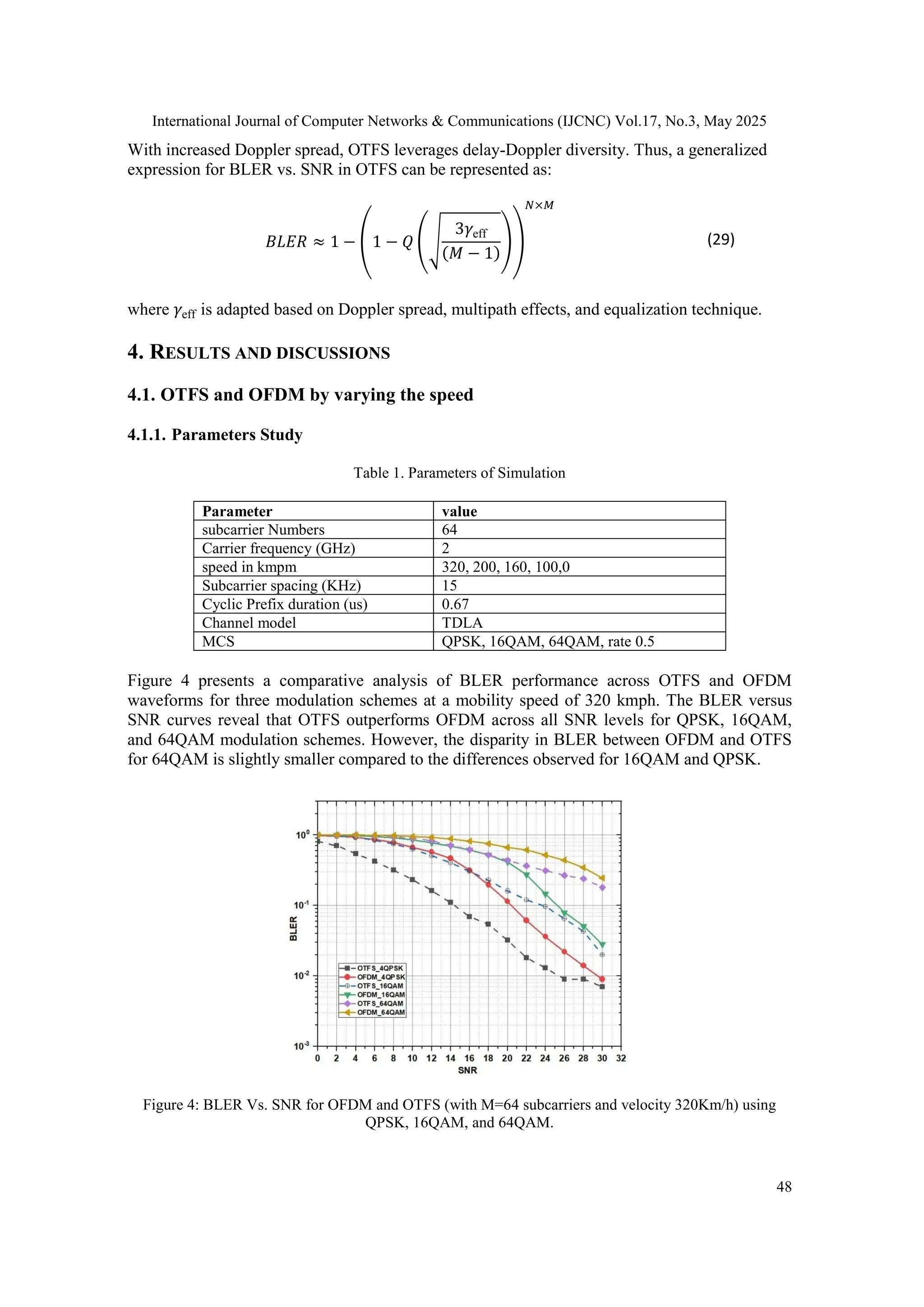
2.5.6. Mathematical Modeling of BLER vs. SNR for OTFS
The Block Error Rate (BLER) in an Orthogonal Time Frequency Space (OTFS) modulation
system depends on several factors, including signal-to-noise ratio (SNR), modulation scheme,
channel conditions, and receiver equalization techniques. Below is a mathematical formulation
of how BLER is modeled in an OTFS system.
For high-mobility conditions, Doppler shifts alter the channel gains, introducing additional SNR
degradation. The effective SNR under Doppler spread can be estimated as [38]:
𝛾eff =
∑ ∣
𝐿
𝑖=1 ℎ𝑖 ∣2
1 +
𝑓𝑑𝑇
𝑀
(28)
where:
𝑓𝑑: Maximum Doppler shift is given by 𝑓𝑑 =
𝑣.𝑓𝑐
𝑐
,
𝑣: Velocity of the receiver (m/s),
𝑓𝑐: Carrier frequency (Hz),
𝑐: Speed of light (m/s),
𝑇: Symbol duration.](https://image.slidesharecdn.com/17325cnc03-250618124506-dacb9608/75/Evaluating-OTFS-Modulation-for-6G-Impact-of-High-Mobility-and-Environmental-Noise-9-2048.jpg)
![International Journal of Computer Networks & Communications (IJCNC) Vol.17, No.3, May 2025
53
5. CONCLUSION
This paper presents an in-depth analysis of Orthogonal Time Frequency Space (OTFS)
modulation, comparing it with Orthogonal Frequency Division Multiplexing (OFDM) to
evaluate its suitability for 6G wireless networks. By leveraging the delay-Doppler domain,
OTFS effectively transforms time-varying channels into quasi-static representations,
significantly enhancing resilience to Doppler effects and ensuring superior Block Error Rate
(BLER) performance in high-mobility scenarios. Simulations conducted across different
mobility speeds, modulation schemes (QPSK, 16QAM, 64QAM), and subcarrier configurations
confirm that OTFS maintains robust signal reliability even under severe channel conditions,
making it a strong candidate for ultra-reliable low-latency communication (URLLC) and
massive IoT applications. Its ability to sustain performance regardless of noise further reinforces
its potential in high-mobility and interference-prone environments. However, to enable real-
world deployment, future research will focus on optimizing computational complexity,
improving channel estimation using machine learning, and integrating OTFS with advanced 6G
technologies such as massive MIMO and reconfigurable intelligent surfaces (RIS). Additionally,
real-world validation through hardware implementations will be explored to assess its feasibility
in high-speed networks. Future work will also investigate fuzzy logic-based channel estimation
techniques to further enhance OTFS adaptability in dynamic environments, strengthening its
position as a next-generation modulation scheme for 6G communications.
CONFLICTS OF INTEREST
The authors declare no conflict of interest.
REFERENCES
[1] Paulo Sergio Rufino Henrique; Ramjee Prasad, "6G The Road to the Future Wireless Technologies
2030," in 6G The Road to the Future Wireless Technologies 2030 , River Publishers, 2021, pp.i-
xxvi.
[2] S. Gupta, M. R. Bhatnagar, and R. S. Kshetrimayum, “OTFS Modulation: Performance Analysis
and Applications in 5G and Beyond,” in Proceedings of the 2023 IEEE Global Communications
Conference (GLOBECOM), 2023.
[3] G. K. Pandey, D. S. Gurjar, H. H. Nguyen and S. Yadav, "Security Threats and Mitigation
Techniques in UAV Communications: A Comprehensive Survey," in IEEE Access, vol. 10, pp.
112858-112897, 2022, doi: 10.1109/ACCESS.2022.3215975.
[4] Q. Li, J. Yuan, M. Qiu, S. Li and Y. Xie, "Low Complexity Turbo SIC-MMSE Detection for
Orthogonal Time Frequency Space Modulation," in IEEE Transactions on Communications, vol.
72, no. 6, pp. 3169-3183, June 2024, doi: 10.1109/TCOMM.2024.3357431.
[5] DARGHOUTHI, Amina, KHLIFI, Abdelhakim, et CHIBANI, Belgacem. “Real time parameter
estimation for adaptive OFDM/OTFS selection”. International Journal of Computer Networks &
Communications (IJCNC) Vol.16, No.4, July 2024 DOI: 10.5121/ijcnc.2024.16406
[6] Li, “Orthogonal Time Frequency Space (OTFS) Modulation for Wireless Communications,” Aug.
2022, [Online]. Available: http://arxiv.org/abs/2208.11807M. Young, The Technical Writer’s
Handbook. Mill Valley, CA: University Science, 1989
[7] G. D. Surabhi, M. K. Ramachandran and A. Chockalingam, "OTFS Modulation with Phase Noise
in mmWave Communications," 2019 IEEE 89th Vehicular Technology Conference (VTC2019-
Spring), Kuala Lumpur, Malaysia, 2019, pp. 1-5, doi: 10.1109/VTCSpring.2019.8746382.
[8] A. Correas-Serrano, N. Petrov, M. Gonzalez-Huici and A. Yarovoy, "Optimized Time-Frequency
Allocation in MIMO NU-OTFS Radar for Enhanced Performance Under Spectral Constraints,"
2024 IEEE Radar Conference (RadarConf24), Denver, CO, USA, 2024, pp. 1-6, doi:
10.1109/RadarConf2458775.2024.10548185](https://image.slidesharecdn.com/17325cnc03-250618124506-dacb9608/75/Evaluating-OTFS-Modulation-for-6G-Impact-of-High-Mobility-and-Environmental-Noise-15-2048.jpg)
![International Journal of Computer Networks & Communications (IJCNC) Vol.17, No.3, May 2025
54
[9] Mounika Siluveru, et al. “Study and Analysis of OTFS and OFDM”. Journal of Artificial
Intelligence,Machine Learning and Neural Network , vol. 2, no. 06, Nov. 2022, pp. 13-23,
doi:10.55529/jaimlnn.26.13.23.
[10] M. Sheikh-Hosseini, F. Rahdari, H. Ghasemnezhad, S. Ahmadi and M. Uysal, "A Comparative
Performance Evaluation of OFDM, GFDM, and OTFS in Impulsive Noise Channels," in IEEE
Open Journal of the Communications Society, doi: 10.1109/OJCOMS.2024.3506723
[11] Vamsi, T. S., Mohanty, H. C., Terlapu, S. K., & Krishna, M. V. (2024). Enhancing 5G Cellular
Communications: A Comparative Analysis of OTFS and GFDM Multiple Access Schemes.
International Journal of Multiphysics, 18(3).
[12] Fish, Alexander, et al. "Delay-Doppler channel estimation in almost linear complexity." IEEE
Transactions on Information Theory 59.11 (2013): 7632-7644.
[13] Li, Shuangyang, et al. "Fundamentals of Delay-Doppler Communications: Practical
Implementation and Extensions to OTFS." arXiv preprint arXiv:2403.14192 (2024).
[14] Yuan, Weijie, et al. "From OTFS to DD-ISAC: Integrating sensing and communications in the
delay doppler domain." IEEE Wireless Communications (2024).
[15] Khuc, Bang, et al. "Channel Estimation and Equalization for OTFS Systems Over High-Mobility
Channels." 2023 International Conference on Electrical Engineering and Photonics (EExPolytech).
IEEE, 2023.
[16] Mohammed, Saif Khan, et al. "OTFS—A mathematical foundation for communication and radar
sensing in the delay-Doppler domain." IEEE BITS the Information Theory Magazine 2.2 (2022):
36-55.
[17] Li, Hua, et al. "OTFS-PDMA Scheme with EPA-Based Receivers for High-Mobility IoT
Networks." IEEE Transactions on Wireless Communications (2023).
[18] Chen, Yuhua, et al. "OTFS waveform based on 3-D signal constellation for time-variant channels."
IEEE Communications Letters 27.8 (2023): 1999-2003.
[19] Balan, Shanmugha, and Sandeep Joshi. "A Study of High-Speed Railway Communication Channel
Models for OTFS-Based Systems." 2024 16th International Conference on COMmunication
Systems & NETworkS (COMSNETS). IEEE, 2024.
[20] Shan, Yaru, and Fanggang Wang. "Low-complexity and low-overhead receiver for OTFS via large-
scale antenna array." IEEE transactions on vehicular technology 70.6 (2021): 5703-5718.
[21] Ahmed, I. Zakir, and Hamid Sadjadpour. "An ML-assisted OTFS vs. OFDM adaptable modem."
2023 IEEE Future Networks World Forum (FNWF). IEEE, 2023.
[22] Suvra Sekhar Das; Ramjee Prasad, "OTFS: Orthogonal Time Frequency Space Modulation A
Waveform for 6G," in OTFS: Orthogonal Time Frequency Space Modulation A Waveform for 6G,
River Publishers, 2021, pp.i-xxvi.
[23] W. Shen, L. Dai, J. An, P. Fan and R. W. Heath, "Channel Estimation for Orthogonal Time
Frequency Space (OTFS) Massive MIMO," in IEEE Transactions on Signal Processing, vol. 67,
no. 16, pp. 4204-4217, 15 Aug.15, 2019, doi: 10.1109/TSP.2019.2919411.
[24] A. Khan and S. K. Mohammed, "A Low-Complexity OTFS Channel Estimation Method for
Fractional Delay-Doppler Scenarios," in IEEE Wireless Communications Letters, vol. 12, no. 9, pp.
1484-1488, Sept. 2023, doi: 10.1109/LWC.2023.3274936.
[25] V. Khammammetti and S. K. Mohammed, "Spectral Efficiency of OTFS Based Orthogonal
Multiple Access with Rectangular Pulses," in IEEE Transactions on Vehicular Technology, vol. 71,
no. 12, pp. 12989-13006, Dec. 2022, doi: 10.1109/TVT.2022.3199478.
[26] K. Pathak, V. Khammammetti and S. K. Mohammed, "Spectral Efficiency Performance of OTFS
Based Multi-Cell Systems," 2023 International Symposium on Networks, Computers and
Communications (ISNCC), Doha, Qatar, 2023, pp. 1-6, doi: 10.1109/ISNCC58260.2023.10323654.
[27] Hadani R, Rakib SS, Monk A, Tsatsanis M, Hebron Y (2020) Orthogonal time frequency space
modulation techniques. Patent Application, US20200259692A1, Cohere Technologies,
LosAngeles, CA, USA
[28] P. Ren, B. Cao, Z. Xiang, L. Yang, B. Xu and Y. Li, "OTFS-Based Downlink Network-Coded
Multiple Access With Joint Amplitude-Phase Design," in IEEE Wireless Communications Letters,
vol. 13, no. 6, pp. 1576-1580, June 2024, doi: 10.1109/LWC.2024.3382152.
[29] P. Priya, E. Viterbo and Y. Hong, "Low Complexity MRC Detection for OTFS Receiver With
Oversampling," in IEEE Transactions on Wireless Communications, vol. 23, no. 2, pp. 1459-1473,
Feb. 2024, doi: 10.1109/TWC.2023.3289610.](https://image.slidesharecdn.com/17325cnc03-250618124506-dacb9608/75/Evaluating-OTFS-Modulation-for-6G-Impact-of-High-Mobility-and-Environmental-Noise-16-2048.jpg)
![International Journal of Computer Networks & Communications (IJCNC) Vol.17, No.3, May 2025
55
[30] R. Hadani et al., "Orthogonal Time Frequency Space Modulation", 2017 IEEE Wireless
Communications and Networking Conference (WCNC), San Francisco, CA, USA, 2017, pp. 1-6,
doi: 10.1109/WCNC.2017.7925924
[31] R. Hadani, S. Rakib, M. Tsatsanis, et al., "Orthogonal Time Frequency Space Modulation," IEEE
Transactions on Wireless Communications, vol. 67, no. 9, pp. 6348-6361, 2018.
[32] T. Datta, N. K. J. Kulkarni, and S. C. S. P. R. Kumar, "Performance of OTFS in Delay-Doppler
Channels," IEEE Transactions on Wireless Communications, vol. 68, no. 6, pp. 4400-4416, 2020.
[33] J. C. O. Nielsen, "Channel Estimation for OTFS Systems," IEEE Communications Letters, vol. 25,
no. 3, pp. 567-570, 2021.
[34] M. K. Sharma and S. Bhattacharjee, "Least Squares and MMSE-based OTFS Channel Estimation,"
IEEE Transactions on Vehicular Technology, vol. 69, no. 2, pp. 1345-1358, 2020.
[35] J. Zhang, L. Wu, and P. Fan, "Channel Estimation in OTFS using MMSE Techniques," IEEE
Transactions on Communications, vol. 69, no. 1, pp. 234-245, 2021.
[36] M. D. Renzo, "OTFS for 6G: A Paradigm Shift in Wireless Communications," IEEE Signal
Processing Magazine, vol. 38, no. 3, pp. 78-94, 2021.
[37] A. Farhang, M. F. P. Fernandes, and R. R. Maciel, "Message Passing Algorithm for OTFS
Detection," IEEE Transactions on Wireless Communications, vol. 71, no. 1, pp. 125-138, 2023.
[38] B. V. S. Reddy, C. Velampalli and S. S. Das, "Performance Analysis of Multi-User OTFS, OTSM,
and Single Carrier in Uplink," in IEEE Transactions on Communications, vol. 72, no. 3, pp. 1428-
1443, March 2024, doi: 10.1109/TCOMM.2023.3332865.
ACKNOWLEDGEMENTS
The authors would like to thank everyone, who has helped and supported this work.
AUTHORS
Abderrahim MOHAMMADI was born in August 1977, in Settat, Morroco. He
enrolled in 2021 to prepare the doctorate in the Laboratory of Innovative Systems
Engineering at the National School of Applied Sciences of Tetouan, Abdelmalek
Essaâdi University, Morocco. His research areas are: Telecommunications systems,
Mobile Networks, Cognitive Radio,
Aziz Dkiouak Professor and Researcher at Chouaib Doukkali University, El Jadida.
He was born in September 1985, in Tayjoute town, 30 Km from Chefchaouen,
Morroco. He received the PhD degree in Electronics and Telecommunications at the
Faculty of Sciences, Abdelmalek Essaadi University, Tetuan, Morocco in 2020. His
research interests focus mainly on printed microwave circuits and
Telecommunications systems. He has authored and co-authored several papers in
international refereed journals and conferences in the field of antenna and
telecommunications.
Mostafa Baghouri was born in Tangier, Morocco. He’s a member in the Complex
Cyber Physical Systems Laboratory (LCCPS), ENSAM of Casablanca, Hassan II
University, Casablanca, Morocco. He’s an associate member in the Information and
Communication Technology Laboratory (LabTIC), ENSA of Tangier, University of
Abdelmalek Essaâdi, Morocco. His research areas are: Wireless Sensor Network,
Telecommunications systems, Mobile Networks, Cognitive Radio, Automation,
detection and diagnosis systems using signal processing methods. In 2002, he obtained
the master’s degree in electrical and computer engineering from the Faculty of
Sciences and Techniques of Tangier, Morocco. He continued his studies to obtain the ENS of Rabat
diploma in the computer science specialty in 2004. In 2006, he received DESA diploma in Automatics and
information processing at the FST of Tangier. Thereafter, He obtained the doctorate degree in Physics and
Embedded System. He has taught at several educational institutions. Currently, he is an assistant](https://image.slidesharecdn.com/17325cnc03-250618124506-dacb9608/75/Evaluating-OTFS-Modulation-for-6G-Impact-of-High-Mobility-and-Environmental-Noise-17-2048.jpg)