VIP Call Girls Service Kondapur Hyderabad Call +91-8250192130
dmct-otfs lab.pptx
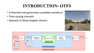
1. INTRODUCTION- OTFS
• A Potential next generation candidate waveform
• Time-varying channels
• Operates in Delay-Doppler domain
2. SYSTEM EQUATIONS- Transmitter
• The transmit signal is first transformed at the transmitter using the ISFFT from the
Delay-Doppler domain into the time-frequency domain, and the time-frequency
signal is expressed as (4)
𝑋𝑇𝐹
[n, m] =
1
𝑁𝑀 𝑧=0
𝑁−1
𝑙=0
𝑀−1
𝑥DD (𝑧, 𝑙)𝑒−𝑗2𝜋(
𝑛𝑧
𝑁
–
𝑚𝑙
𝑀
)
with n = 0…N-1 and m = 0,.M-1.
• The Heisenberg transform can then be used to get the time-domain signal s(t)
from the time-frequency signal XTF [n, m]
s(t)= 𝑛=0
𝑁−1
𝑚=0
𝑀−1
XTF 𝑛, 𝑚 𝑔𝑡𝑥 𝑡 − 𝑛𝑇 𝑒𝑗2𝜋𝑚∆𝑓 𝑡−𝑛𝑇
where 𝑔𝑡𝑥 𝑡 − 𝑛𝑇 is the transmit pulse, T is the length of an OTFS symbol, and f is
the distance in frequency between two OTFS slots that are close to one another.
3. SYSTEM EQUATIONS- Transmission and Channel
• The time-domain signals S (t) expresses the transmit signal matrix for all transmit antennas with time domain
components
𝑺 𝑡 =
𝑆1(1) 𝑆1(2) … 𝑆1(𝑁𝑀)
𝑆2(1) 𝑆2(2) … 𝑆2(𝑁𝑀)
⋮ ⋮ ⋱ ⋮
𝑆𝑁𝑡
(1) 𝑆𝑁𝑡
(2) … 𝑆𝑁𝑡
(𝑁𝑀)
• The received time-domain signal is calculated as the additive white Gaussian noise (AWGN) n(t) at the receiver
is,
r(t)= ℎ 𝜏, 𝑣 𝑠 𝑡 − 𝜏 𝑒𝑗2𝜋𝑣 𝑡−𝜏 𝑑𝜏𝑑𝑣 + 𝑛 𝑡
𝑯 𝑡 =
𝒉11(𝑡) 𝒉12(𝑡) … 𝒉1𝑁𝑡
(𝑡)
𝒉21(𝑡) 𝒉22(𝑡) … 𝒉2𝑁𝑡
(𝑡)
⋮ ⋮ ⋱ ⋮
𝒉𝑁𝑟1(𝑡) 𝒉𝑁𝑟2(𝑡) … 𝒉𝑁𝑟𝑁𝑡
(𝑡)
where, 𝒉𝑞𝑝 𝑡 = ℎ𝑞𝑝
1 (𝑡) … ℎ𝑞𝑝
𝑖 (𝑡) … ℎ𝑞𝑝
𝑃 (𝑡)
𝑇
utilising the formula ℎ𝑞𝑝
𝑖
(t)=𝛼𝑞𝑝𝑖
𝑒𝑗2𝜋𝜗𝑖𝑡
𝛿(𝑡 − 𝜏𝑖) where
𝛼𝑞𝑝𝑖
, 𝜏𝑖 and 𝜗𝑖 are the ith path's channel coefficient, latency, and Doppler shift, respectively. The channel coefficient
is a complex Gaussian random variable designated as CN(0, 1) with a zero mean and unit variance.
4. SYSTEM EQUATIONS- Channel
• The received channel response of the pth transmit antenna to the qth receiver is
given by
ℎ𝑞𝑝
𝐷𝐷 𝑧, 𝑙 = ℎ𝑞𝑝 𝜏, 𝑣 𝜔(𝑧 − 𝑣, 𝑙 − 𝜏)𝑒−𝑗2𝜋𝑣𝜏𝑑𝜏𝑑𝑣
Where,
ℎ𝑞𝑝 𝜏, 𝑣 = 𝑖=1
𝑃
𝛼𝑞𝑝𝑖
𝛿( 𝜏 − 𝜏𝑖)𝛿(𝑣 − 𝑣𝑖), 𝜔 𝜏, 𝑣 = 𝑧=0
𝑁−1
𝑙=0
𝑀−1
𝑒−𝑗2𝜋 𝑣𝑧𝑇−𝜏𝑙Δ𝑓
• The time-variant channel response vector from the pth transmit antenna to the
qth receive antenna is denoted by the notation hqp(t) ∈ CPx1.
5. SYSTEM EQUATIONS- Reception
• The Wigner transform, which is the inverse of the Heisenberg transform, can be used to
obtain the time-frequency domain signal YTF [n, m] from r(t), and it can then be
expressed as
YTF [n , m] = 𝐴𝑔𝑟𝑥, 𝜏, 𝜈 𝜏=𝑛𝑇,𝜈=𝑚∆𝑓
and 𝐴𝑔𝑟𝑥, 𝑟 𝜏, 𝜈 = 𝑔𝑟𝑥
∗ 𝑡 − 𝜏 𝑟 𝑡 𝑒−𝑗2𝜋𝑣 𝑡−𝜏 𝑑𝑡
where 𝐴𝑔𝑟𝑥, 𝑟 𝜏, 𝜈 denotes the cross ambiguity function and grx (·) is the received pulse.
• Then, the received delay-Doppler domain signal 𝑦𝐷𝐷(𝑧 , 𝑙) can be obtained from YTF [n ,
m] in the time-frequency domain according to the SFFT as,
𝑦𝐷𝐷
(𝑧 , 𝑙)=
1
𝑁𝑀 𝑛=0
𝑁−1
𝑚=0
𝑀−1
𝑌𝑇𝐹
𝑛, 𝑚 𝑒
−𝑗2𝜋
𝑛𝑧
𝑁
−
𝑚𝑙
𝑀
• ML/MRC detection is performed for demodulation of data bits
𝑢 = arg max
𝑢
𝒉𝐷𝐷 𝑧,𝑙 𝑢
𝐻
𝒚𝐷𝐷(𝑧,𝑙)
𝒉𝐷𝐷 𝑧,𝑙 𝑢 𝐹
𝑥𝑚
𝐷𝐷
= arg min
𝑥𝑚
𝐷𝐷
𝑦𝐷𝐷
𝑧 , 𝑙 − ℎ𝐷𝐷
𝑧, 𝑙 𝑢𝑥𝑚
𝐷𝐷
𝐹
2

![SYSTEM EQUATIONS- Transmitter
• The transmit signal is first transformed at the transmitter using the ISFFT from the
Delay-Doppler domain into the time-frequency domain, and the time-frequency
signal is expressed as (4)
𝑋𝑇𝐹
[n, m] =
1
𝑁𝑀 𝑧=0
𝑁−1
𝑙=0
𝑀−1
𝑥DD (𝑧, 𝑙)𝑒−𝑗2𝜋(
𝑛𝑧
𝑁
–
𝑚𝑙
𝑀
)
with n = 0…N-1 and m = 0,.M-1.
• The Heisenberg transform can then be used to get the time-domain signal s(t)
from the time-frequency signal XTF [n, m]
s(t)= 𝑛=0
𝑁−1
𝑚=0
𝑀−1
XTF 𝑛, 𝑚 𝑔𝑡𝑥 𝑡 − 𝑛𝑇 𝑒𝑗2𝜋𝑚∆𝑓 𝑡−𝑛𝑇
where 𝑔𝑡𝑥 𝑡 − 𝑛𝑇 is the transmit pulse, T is the length of an OTFS symbol, and f is
the distance in frequency between two OTFS slots that are close to one another.](data:image/gif;base64,R0lGODlhAQABAIAAAAAAAP///yH5BAEAAAAALAAAAAABAAEAAAIBRAA7)