SlideShare a Scribd company logo
1 of 15
Download to read offline
Printed by Jouve, 75001 PARIS (FR)
(19)EP3231989A2
TEPZZ¥ ¥_989A T
(11) EP 3 231 989 A2
(12) EUROPEAN PATENT APPLICATION
(43) Date of publication:
18.10.2017 Bulletin 2017/42
(21) Application number: 17156241.6
(22) Date of filing: 15.02.2017
(51) Int Cl.:
F01D 5/00 (2006.01)
F01D 5/28 (2006.01)
(84) Designated Contracting States:
AL AT BE BG CH CY CZ DE DK EE ES FI FR GB
GR HR HU IE IS IT LI LT LU LV MC MK MT NL NO
PL PT RO RS SE SI SK SM TR
Designated Extension States:
BA ME
Designated Validation States:
MA MD
(30) Priority: 18.02.2016 US 201615046730
(71) Applicant: General Electric Company
Schenectady, NY 12345 (US)
(72) Inventors:
• GUPTA, Bhupendra Kumar
Cincinnati, OH 45215 (US)
• ROSENZWEIG, Mark
Cincinnati, OH 45215 (US)
(74) Representative: Williams, Andrew Richard et al
GE International Inc.
GPO-Europe
The Ark
201 Talgarth Road
Hammersmith
London W6 8BJ (GB)
(54) SYSTEM AND METHOD FOR REJUVENATING COATED COMPONENTS OF GAS TURBINE
ENGINES
(57) The present disclosure is directed to a method
for rejuvenating a damaged coated component of a gas
turbine engine (10). The method includes uninstalling the
damaged coated component from the gas turbine engine
(10). The method also includes isolating a first coated
portion (105) of the component of the gas turbine engine
(10) from a second coated portion (108) of the compo-
nent. In addition, the method includes simultaneously de-
positing a first coating material (112) on the first coated
portion (105) of the component and a different, second
coating material (114) onthe secondcoatedportion (108)
of the component. The method also includes reinstalling
the rejuvenated coated component into the gas turbine
engine (10).
EP 3 231 989 A2
2
5
10
15
20
25
30
35
40
45
50
55
Description
FIELD OF THE INVENTION
[0001] The present invention relates generally to gas
turbine engines, and more specifically, to systems and
methods for rejuvenating coated components, such as
turbine blades, by simultaneously depositing multiple
coatings thereon.
BACKGROUND OF THE INVENTION
[0002] A gas turbine engine generally includes, in se-
rial flow order, a compressor section, a combustion sec-
tion, a turbine section and an exhaust section. In opera-
tion, air enters an inlet of the compressor section where
one or more axial or centrifugal compressors progres-
sively compress the air until it reaches the combustion
section. Fuel is mixed with the compressed air and
burned within the combustion section to provide combus-
tion gases. The combustion gases are routed from the
combustion section through a hot gas path defined within
the turbine section and then exhausted from the turbine
section via the exhaust section.
[0003] In particular configurations, the turbine section
includes, in serial flow order, a high pressure (HP) turbine
and a low pressure (LP) turbine. The HP turbine and the
LP turbine each include various rotatable turbine com-
ponents such as a rotor shaft, rotor disks mounted or
otherwise carried by the rotor shaft, turbine blades
mounted to and radially extending from the periphery of
the disks, and various stationary turbine components
such as stator vanes or nozzles, turbine shrouds, and
engine frames. The rotatable and stationary turbine com-
ponents at least partially define the hot gas path through
the turbine section. For example, the gas turbine buckets
or blades generally have an airfoil shape designed to
convert the thermal and kinetic energy of the flow path
gases into mechanical rotation of the rotor. As the com-
bustion gases flow through the hot gas path, thermal en-
ergy is transferred from the combustion gases to the ro-
tatable and stationary turbine components.
[0004] Turbine blades maybe constructed of a number
of superalloys (e.g., nickel-based superalloys), as well
as ceramic matrix composites coated with an environ-
mental barrier coating to avoid oxidation and recession
in the presence of high temperature steam during oper-
ation of the engine. Current coating processes for engine
components include atwo-stepprocessthat first includes
coating a first portion of the component with a corrosion-
resistant coating (such as a chromide coating) and then
subsequently includes coating a second portion of the
component with an oxidation-prohibiting coating, such
as an aluminide coating. For example, for high-pressure
turbine blades, the shank is first coated via a pack proc-
ess using a powder chromide coating and a later step
includes coating the airfoil of the turbine blade with an
aluminide coating.
[0005] One of the issues associated with conventional
two-step coating techniques, however, includes chloride
gases leaking from the pack during the chromide coating
process which can damage the airfoil. More specifically,
in engine components with internal aluminide coatings,
the depletion of aluminum due to reaction with chloride
gases can result in low engine performance and/or a high
scrap rate.
[0006] In addition, during operation of the gas turbine
engine, the coatings originally applied to the turbine
blades begin to wear off due to oxidation and other en-
vironmental conditions within the turbine engine. Con-
ventional repair methods for turbine blades require "full
repair" of the affected blades, which includes uninstalling
theturbineblade from the engine, stripping thepreviously
applied coatings therefrom, and repeating the two-step
process described above. Thus, full repair of the turbine
blades can be time-consuming and expensive.
[0007] In view of theaforementioned, animprovedsys-
tem and method for rejuvenating coated turbine blades
rather than requiring full repair of such blades would be
advantageous. More specifically, a system and method
for rejuvenating turbine blades by simultaneously depos-
iting multiple coatings on the previously-coated blade
would be desired in the art.
BRIEF DESCRIPTION OF THE INVENTION
[0008] Aspects and advantages of the invention will be
set forth in part in the following description, or may be
obvious from the description, or may be learned through
practice of the invention.
[0009] In one aspect, the present disclosure is directed
to a method for rejuvenating a damaged coated compo-
nent of a gas turbine engine. The method includes unin-
stalling the damaged coated component from the gas
turbine engine. The method also includes isolating a first
coatedportionof the componentof the gas turbine engine
from a second coated portion of the component. In ad-
dition, the method includes simultaneously depositing a
first coating material on the first coated portion of the
component and a different, second coating material on
the second coatedportion of the component. The method
also includes reinstalling the rejuvenated coated compo-
nent into the gas turbine engine.
[0010] In another aspect, the present disclosure is di-
rected to a kit for rejuvenating a damaged coated com-
ponent of a gas turbine engine. The kit includes a first
coating material and a second coating material, wherein
the first and second coating materials are different. The
kit also includes a maskant for isolating a first coated
portion of the component of the gas turbine engine from
a second coated portion of the component and a coating
system configured to simultaneously deposit the first and
second coating materials on the first and second coated
portions of the component, respectively.
[0011] In yet another aspect, the present disclosure is
directed to a method for rejuvenating a damaged coated
1 2
EP 3 231 989 A2
3
5
10
15
20
25
30
35
40
45
50
55
turbine blade of a gas turbine engine. The method in-
cludes uninstalling the damaged coated turbine blade
from the gas turbine engine. The method also includes
placing a coated shank of the turbine blade in a masking
chamber having a masking lid so as to isolate the shank
from a coated airfoil of the turbine blade. Another step
includes filling a masking chamber with a chromium-
based powder coating. Thus, the method also includes
simultaneously depositing an aluminum-based coating
on the airfoil via diffusion coating.
[0012] These and other features, aspects and advan-
tages of the present invention will become better under-
stood with reference to the following description and ap-
pended claims. The accompanying drawings, which are
incorporated in and constitute a part of this specification,
illustrateembodiments of the invention and, together with
the description, serve to explain the principles of the in-
vention.
BRIEF DESCRIPTION OF THE DRAWINGS
[0013] The subject matter which is regarded as the in-
vention is particularly pointed out and distinctly claimed
in the concluding part of the specification. The invention,
however, may be best understood by reference to the
following description taken in conjunction with the ac-
companying drawing figures in which:
FIG. 1 illustrates a schematic cross-sectional view
of oneembodiment ofa gasturbineengineaccording
to the present disclosure;
FIG. 2 illustrates a perspective view of one embod-
iment of a turbine blade of a gas turbine engine ac-
cording to the present disclosure;
FIG. 3 illustrates a schematic view of one embodi-
ment of akit for rejuvenating adamagedcoatedcom-
ponent of a gas turbine engine according to the
present disclosure;
FIG. 4 illustrates a schematic flow diagram of one
embodiment of a process steps for rejuvenating a
damaged coated component of a gas turbine engine
according to the present disclosure; and
FIG. 5 illustrates a flow diagram of one embodiment
of a method for rejuvenating a damaged coated com-
ponent of a gas turbine engine according to the
present disclosure.
DETAILED DESCRIPTION OF THE INVENTION
[0014] Reference now will be made in detail to embod-
iments of the invention, one or more examples of which
are illustrated in the drawings. Each example is provided
by way of explanation of the invention, not limitation of
the invention. In fact, it will be apparent to those skilled
in the art that various modifications and variations can
be made in the present invention without departing from
the scope or spirit of the invention. For instance, features
illustrated or described as part of one embodiment can
be used with another embodiment to yield a still further
embodiment. Thus, it is intended that the present inven-
tion covers such modifications and variations as come
within the scope of the appended claims and their equiv-
alents.
[0015] Chemical elements are discussed in the
present disclosure using their common chemical abbre-
viation, such as commonly found on a periodic table of
elements. For example, aluminum is represented by its
common chemical abbreviation Al; chromium is repre-
sented by its common chemical abbreviation Cr; and so
forth.
[0016] As used herein, the terms "first", "second", and
"third" may be used interchangeably to distinguish one
component from another and are not intended to signify
location or importance of the individual components.
[0017] The terms "upstream" and "downstream" refer
to the relative direction with respect to fluid flow in a fluid
pathway. For example, "upstream" refers to the direction
from which the fluid flows, and "downstream" refers to
the direction to which the fluid flows.
[0018] Generally, the present disclosure is directed to
an improved system and method for rejuvenating dam-
aged coated components of gas turbine engines by si-
multaneously depositing multiple coatings at different lo-
cations on the component. More specifically, in certain
embodiments, the method includes uninstalling the dam-
aged coated component from the gas turbine engine and
isolating a first coated portion of the component from a
second coated portion of the component. For example,
thecomponentmayincludeaturbinebladehavingacoat-
ed airfoil and a shank that may or may not be coated.
Thus, the method includes simultaneously depositing a
first coating material on the first coated or uncoated por-
tion (i.e. the shank) of the component and a different,
second coating material on the second coated portion
(i.e. the airfoil) of the component. The method also in-
cludes reinstalling the rejuvenated coated component in-
to the gas turbine engine.
[0019] As such, even though the chromium-based
powder and the aluminum-based material are deposited
onto the turbine blade simultaneously, the coating mate-
rials do not contact each other or neighboring portions
of the blade. Thus, the present disclosure provides a ro-
bust process that reduces time and costs associated with
coating engine components. Further, by depositing the
coating materials at the same time, degradation of the
coating materials is minimized. In addition, previously-
applied coatings do not need to be removed from the
component before the rejuvenation process begins. By
not removing the previously-applied coatings from the
component, the present disclosure enhances the life of
the part.
[0020] Referring now to the drawings, FIG. 1 illustrates
3 4
EP 3 231 989 A2
4
5
10
15
20
25
30
35
40
45
50
55
a schematic cross-sectional view of one embodiment of
a gas turbine engine 10 (high-bypass type) according to
the present disclosure. More specifically, the gas turbine
engine 10 may include an aircraft engine, e.g. for an air-
plane, helicopter, or similar. As shown, the gas turbine
engine 10 has an axial longitudinal centerline axis 12
therethrough for reference purposes. Further, as shown,
the gas turbine engine 10 preferably includes a core gas
turbine engine generally identified by numeral 14 and a
fan section 16 positioned upstream thereof. The core en-
gine 14 typically includes a generally tubular outer casing
18 that defines an annular inlet 20. The outer casing 18
further encloses and supports a booster 22 for raising
the pressure of the air that enters core engine 14 to a
first pressure level. A high pressure, multi-stage, axial-
flow compressor 24 receives pressurized air from the
booster 22 and further increases the pressure of the air.
The compressor 24 includes rotating blades and station-
ary vanes that have the function of directing and com-
pressingair within the turbine engine10. The pressurized
air flows to a combustor 26, where fuel is injected into
the pressurized air stream and ignited to raise the tem-
perature and energy level of the pressurized air. The high
energy combustion products flow from the combustor 26
to a first (high pressure) turbine 28 for driving the high
pressure compressor 24 through a first (high pressure)
drive shaft 30, and then to a second (low pressure) tur-
bine 32 for driving the booster 22 and the fan section 16
through a second (low pressure) drive shaft 34 that is
coaxial with the first drive shaft 30. After driving each of
the turbines 28 and 32, the combustion products leave
the core engine 14 through an exhaust nozzle 36 to pro-
vide at least a portion of the jet propulsive thrust of the
engine 10.
[0021] The fan section 16 includes a rotatable, axial-
flow fan rotor 38 that is surrounded by an annular fan
casing 40. It will be appreciated that fan casing 40 is
supported from the core engine 14 by a plurality of sub-
stantially radially-extending, circumferentially-spaced
outlet guide vanes 42. In this way, the fan casing 40 en-
closes the fan rotor 38 and the fan rotor blades 44. The
downstream section 46 of the fan casing 40 extends over
an outer portion of the core engine 14 to define a sec-
ondary, or bypass, airflow conduit 48 that provides addi-
tional jet propulsive thrust.
[0022] From a flow standpoint, it will be appreciated
that an initial airflow, represented by arrow 50, enters the
gasturbine engine 10through aninlet 52tothefancasing
40. The airflow passes through the fan blades 44 and
splits into a first air flow (represented by arrow 54) that
moves through the conduit 48 and a second air flow (rep-
resented by arrow 56) which enters the booster 22.
[0023] The pressure of the second compressed airflow
56 is increased and enters the high pressure compressor
24, as represented by arrow 58. After mixing with fuel
and being combusted in the combustor 26, the combus-
tion products 60 exit the combustor 26 and flow through
the first turbine 28. The combustion products 60 then flow
throughthesecondturbine32andexit theexhaust nozzle
36 to provide at least a portion of the thrust for the gas
turbine engine 10.
[0024] Still referring to FIG. 1, the combustor 26 in-
cludes an annular combustion chamber 62 that is coaxial
with the longitudinal centerline axis 12, as well as an inlet
64 and an outlet 66. As noted above, the combustor 26
receives an annular stream of pressurized air from a high
pressure compressor dischargeoutlet 69. Fuel isinjected
from a fuel nozzle to mix with the air and form a fuel-air
mixture that is provided to the combustion chamber 62
for combustion. Ignition of the fuel-air mixture is accom-
plished by asuitableigniter, and the resultingcombustion
gases 60 flow in an axial direction toward and into an
annular, first stage turbine nozzle 72. The nozzle 72 is
defined by an annular flow channel that includes a plu-
rality of radially-extending, circumferentially-spaced noz-
zle vanes 74 that turn the gases so that they flow angu-
larly and impinge upon the first stage turbine blades 43
of the first turbine 28. Similarly, the second stage turbine
32 may include a plurality of second stage turbine blades
45. As shown in FIG. 1, the first turbine 28 preferably
rotates the high-pressure compressor 24 via the first
drive shaft 30, whereas the low-pressure turbine 32 pref-
erably drives the booster 22 and the fan rotor 38 via the
second drive shaft 34.
[0025] Referring now to FIG. 2, an exemplary turbine
blade 100 of the gas turbine engine 10 of FIG. 1 is illus-
trated. As shown, the blade 100 is generally represented
as being adapted for mounting to a disk or rotor (not
shown) within the turbine section of the gas turbine en-
gine 10. For this reason, the turbine blade 100 is repre-
sented asincludinga dovetail 102 for anchoring theblade
100toaturbinediskbyinterlockingwithacomplementary
dovetail slot formed in the circumference of the disk. As
represented in FIG. 2, the interlocking features may in-
clude protrusions referred to as tangs 104 that engage
recesses defined by the dovetail slot. The blade 100 is
further shown as having a platform 106 that separates
an airfoil 108 from a shank 105 on which the dovetail 102
is defined. The turbine blade 100 also includes a blade
tip 109 disposed opposite the platform 106. As such, the
blade tip109generally definesthe radiallyoutermost por-
tion of the blade 100 and, thus, may be configured to be
positioned adjacent to a stationary shroud (not shown)
of the gas turbine engine 10.
[0026] Because they are directly subjected to hot com-
bustion gases during operation of the engine, the airfoil
108, platform 106, and/or blade tip 109 typically have
verydemandingmaterial requirements. Theplatform 106
and the blade tip 109 are further critical regions of the
turbine blade 100 in that they create the inner and outer
flowpath surfaces for the hot gas path within the turbine
section. In addition, the platform 106 creates a seal to
prevent mixing of the hot combustion gases with lower
temperature gases to which the shank 105, its dovetail
102, and the turbine disk are exposed. Further, the blade
tip 109 may be subjected to creep due to high strain loads
5 6
EP 3 231 989 A2
5
5
10
15
20
25
30
35
40
45
50
55
and wear interactions between it and the shroud sur-
rounding the blade tips 109. The dovetail 102 is also a
critical region in that it is subjected to wear and high loads
resulting from its engagement with a dovetail slot and the
high centrifugal loading generated by the blade 100.
[0027] Thus, the turbine blade 100 (or portions thereof)
is typically coated with various coatings that are depend-
ent on turbine operations and associated temperatures.
For example, in particular embodiments, the shank 105
may have been previously coated with a chromium-
based material, whereas the airfoil 108 may have been
previouslycoatedwithanaluminum-based material. Dur-
ing operation, such coatings begin to wear off due to ox-
idation and other environmental conditions within the tur-
bine engine 10. Thus, the present disclosure is directed
to systems and methods for rejuvenating such turbine
blades. Though the present disclosure is described in
reference to a turbine blade, it should be understood that
the coating systems and methods as described herein
may be applied to any gas turbine engine component.
For example, in certain embodiments, the gas turbine
engine components that may be coated according to the
present disclosure in addition to the turbine blade may
include but are not limited to fan blades, compressor
blades, nozzles, shrouds, shroud supports, frames, tur-
bine vanes, guide vanes, compressor vanes, or similar.
[0028] Referring now to FIG. 3, a schematic view of a
kit 110 for rejuvenating such coated components, e.g.
the coated turbine blades 100, of the gas turbine engine
10 is illustrated. As shown, the kit 110 includes a first
coating material 112 and a second, different coating ma-
terial 114. Although the kit 110 is illustrated having two
coating materials, it should be understood by those of
ordinary skill in the art that any number of coating mate-
rials may be used according to the present disclosure.
Further, the first and second coating materials 112, 114
may include any suitable coatings, including but not lim-
ited to chromium-based coatings, aluminum-based coat-
ings, silicon-based coatings, platinum coatings, palladi-
um coatings, or any other suitable coating materials. For
example, the chromium-based coatings as described
herein may include the chromium coating and related
chromizing process as described in U.S. Patent Applica-
tion Publication No.: 2010/0151124 entitled "Slurry Chr-
omizing Process" filed on August 3, 2007, which is incor-
porated herein by reference in its entirety. More specifi-
cally, in particular embodiments, the coating materials
112, 114 may include aluminide (i.e. Al coating over a
Ni, Co, or Fe base alloy), chromide (i.e. Cr coating over
Ni, Co, or Fe base alloy), silicide (i.e. silicon coating over
Ni, Co, Fe base alloy), Pt-Al (i.e. platinum plating then
an aluminide coating), Pd-Al (i.e. palladium plating then
an aluminide coating, Hf-Al (i.e. hafniding and aluminid-
ing), Cr-Al on one surface with pure chromide or alumi-
nide on another surface, Al-Si on one surface with pure
Cr or Al on another surface, Al with 5%Si/Cr coating, or
any other suitable coatings or combinations thereof.
[0029] The kit 110 also includes a maskant 116 for iso-
lating a first coated portion of the component from a sec-
ond coated portion of the component. More specifically,
as shown in the illustrated embodiment, the maskant 116
may include a masking chamber 118. In such an embod-
iment, the masking chamber 118 is configured to receive
a first coated portion of the component, i.e. the coated
shank 105 of the turbine blade 100, so as to isolate the
first coated portion from the second coated portion, i.e.
the airfoil 108 of the turbine blade 100, which is described
in more detail in regards to FIG. 4 below.
[0030] Further, asshown, thekit 110 includes acoating
system 120 configured to simultaneously deposit the first
and second coating materials 112, 114 on the first and
second coated portions 105, 108 of the component, re-
spectively. For example, in one embodiment, the mask-
ing chamber 116 may be filled with the first coating ma-
terial 112, e.g. a chromium-based powder. In addition,
as shown, the coating system 120 may include a coating
furnace 122 configured to apply the second coating ma-
terial 114 on the second coated portion 108 of the com-
ponent, i.e. the airfoil 108 of the turbine blade 100 as the
first coating material is coating the first coated portion of
the component. Thus, in such embodiments, the second
coating material 114 may include a vapor-based alumi-
nide material.
[0031] Referring now to FIG. 4, a schematic flow dia-
gram of one embodiment of a process 200 for rejuvenat-
ing a previously coated turbine blade 100 of the gas tur-
bine engine10isillustrated. Asshown at 202,theprocess
200 includes providing an empty masking chamber 118
with optional locating tangs that are configured to engage
the tang 104 of shank 105 of the turbine blade 100 so as
to retain the turbine blade 100 therein. Thus, as shown
at 204, the process 200 includes uninstalling the turbine
blade 100 from the engine 10 and placing the coated
turbine blade 100 within the masking chamber 118. As
shown at 206, the process 200 includes filling the mask-
ingchamber 118tothe platform edge with thefirst coating
material 112, which as mentioned, may be a chromium-
based powder. As shown at 208, the process 200 in-
cludesplacinga masking lid 119 on themaskingchamber
118 so as to isolate the airfoil 108 of the turbine blade
100 from the shank 105 of the turbine blade 100. As
shown at 210, the process 200 may also optionally in-
clude placing an additional maskant 117 (e.g. a maskant
film or similar) around the masking lid 119 and the top of
the masking chamber 118 so as to further isolate the
airfoil 108 of the turbine blade 100 from the shank 105
of the turbine blade 100. Such isolation prevents the first
coating material 112 from damaging the airfoil 108 of the
turbine blade 100. As shown at 212, the process 200
includes placing the turbine blade 100 (or a plurality of
turbine blades 100) in the coating furnace 122. Thus, the
method 200 includes simultaneously depositing the first
coating material 112ontheshank105of theturbineblade
100 and the second coating material 114 on the airfoil
108 of the turbine blade 100, i.e. via the coating furnace
122.
7 8
EP 3 231 989 A2
6
5
10
15
20
25
30
35
40
45
50
55
[0032] More specifically, in certain embodiments, the
coating furnace 122 is configured to apply the second
coating material 114 via diffusion coating. For typical dif-
fusion coating processes, aluminum-based materials
(e.g. aluminides), chrome-based materials, and/or sili-
con-based materials may be mixed with an activator (e.g.
a halide activator) and heated via the coating furnace
122 to form gaseous metal compounds which result in
the deposition of the metal on the surface of the part to
be coated, i.e. the airfoil 108 of the turbine blade 100.
Suitable temperatures for diffusion coating processes
may be from about 1500°F (about 815°C) to about
2200°F (about 1205°C), more preferably from about
1900°F (about 1040°C) to about 2100°F (about 1150°C).
Further, the turbine blade 100 may remain in the coating
furnace 122 for any suitable amount of time during the
diffusion coating process depending on a desired thick-
ness of the coating. For example, in one embodiment,
the turbine blade 100 may remain in the coating furnace
from about one (1) hour to about ten (10) hours. In addi-
tional embodiments, the turbine blade 100 may remain
in the coating furnace 122 for less than one hour or for
greater than ten hours. Thus, the gaseous metal com-
pounds decompose upon contact with the surfaces of
the part, thereby depositing the diffusion coating on the
surface thereof. In additional embodiments, the airfoil
108 (or second coated portion of the component) may
coated using any other suitable coating techniques in
addition to diffusion coating, including but not limited to
slurry coating, plating, and/or pack or powder coating.
[0033] As shown at 214, the process 200 further in-
cludes removing the turbine blade 100 from the coating
furnace 122 and allowing the blade 100 to cool. As shown
at 216, the masking lid 119 can then be removed from
atop the masking chamber 118. As shown at 218, the
coated turbine blade 100 is removed from the masking
chamber 118. Thus, the previously-coated turbine blade
100 of the present disclosure is rejuvenated using a sin-
gle-step coatingprocess(i.e. bothcoatingsaredeposited
ontotheblade100indifferent locationsat the same time).
[0034] Referring now to FIG. 5, a flow diagram of one
embodiment of a method 300 for coating a component
of a gas turbine engine 10 is illustrated. As shown at 302,
the method 300 includes uninstalling the damaged coat-
ed component from the gas turbine engine 10. As men-
tioned, the component of the gas turbine engine 10 may
include any suitable component such as a turbine blade,
a fan blade, a compressor blade, a nozzle, shrouds,
shroud supports, frames, a turbine vane, a guide vane,
or a compressor vane.
[0035] As shown at 304, the method 300 includes iso-
lating a first coated portion of the component of the gas
turbine engine from a second coated portion of the com-
ponent. More specifically, where the coated component
is a turbine blade 100, the step of isolating the first coated
portion of the blade 100 of the gas turbine engine 10 from
the second coated portion of the blade 100 may include
placing a shank of the blade 100 in a masking chamber
and placing a masking lid on the masking chamber
against a platform of an airfoil of the blade so as to isolate
the shank from the airfoil.
[0036] As shown at 306, the method 300 also includes
simultaneously depositing a first coating material on the
first coated portion of the component and a different, sec-
ond coating material on the second coated portion of the
component. In certain embodiments, the step of simul-
taneously depositing the first coating material on the first
coated portion of the component and the second coating
material on the second coated portion of the component
may include diffusion coating, plating, slurry coating,
powder coating, or any other suitable coating process.
As shown at 308, the method 300 includes reinstalling
the rejuvenated coated component into the gas turbine
engine 10.
[0037] Further, the first and second coating materials
may include chromium-based coatings, aluminum-
based coatings, silicon-based coatings, platinum coat-
ings, palladium coatings, or any other suitable coating
materials such as those described herein. More specifi-
cally, the first coating material may include a chromium-
based material, whereas the second coating material
may include an aluminum-based material. In such em-
bodiments, the step of simultaneously depositing the first
coating material on the first coated portion of the com-
ponent and the second coating material on the second
coated portion of the component may include filling the
masking chamber with the chromium-based material be-
fore placing the masking lid on the masking chamber so
as to coat the shank and depositing the airfoil with the
aluminum-based material.
[0038] In additional embodiments, the step of depos-
iting the airfoil with the aluminum-based material may
include placing the turbine blade in a coating furnace and
exposing the airfoil to a vapor phase aluminum-based
material so as to coat the airfoil, as previously described.
[0039] In yet another embodiment, the method 300
may further include removing the turbine blade 100 from
the coating furnace, cooling the turbine blade 100 while
the shank remains in the masking chamber, removing
the masking lidfrom the masking chamber, and removing
the shank from the masking chamber.
[0040] This written description uses examples to dis-
close the invention, including the best mode, and also to
enable any person skilled in the art to practice the inven-
tion, including making and using any devices or systems
and performing any incorporated methods. The patent-
able scope of the invention is defined by the claims, and
may include other examples that occur to those skilled
in the art. Such other examples are intended to be within
the scope of the claims if they include structural elements
that do not differ from the literal language of the claims,
or if they include equivalent structural elements with in-
substantial differences from the literal languages of the
claims.
[0041] Various aspects and embodiments of the
present invention are defined by the following numbered
9 10
EP 3 231 989 A2
7
5
10
15
20
25
30
35
40
45
50
55
clauses. Any features or elements of any of the aspects
or embodiments may be readily combined.
1. Amethodfor rejuvenating adamagedcoatedcom-
ponent of a gas turbine engine, the method compris-
ing:
uninstalling the damaged coated component
from the gas turbine engine;
isolating a first coated portion of the component
of the gas turbine engine from a second coated
portion of the component;
simultaneously depositing a first coating mate-
rial on the first coated portion of the component
and a different, second coating material on the
second coated portion of the component; and,
reinstalling the rejuvenated coated component
into the gas turbine engine.
2. The method of clause 1, wherein the coated com-
ponent of the gas turbine engine comprises at least
one of a turbine blade, a fan blade, a compressor
blade, a nozzle, shrouds, shroud supports, frames,
a turbine vane, a guide vane, or a compressor vane.
3. The method of clause 1 or 2, wherein simultane-
ously depositing the first coating material on the first
coated portion of the component and the second
coating material on the second coated portion of the
component comprises at least one of diffusion coat-
ing, plating, slurry coating, or powder coating.
4. The method of any preceding clause, wherein the
first coated portion comprises a shank of the turbine
blade and the second coated portion comprises an
airfoil of the turbine blade.
5. The method of any preceding clause, wherein the
shank was previously coated with a chromium-
based material and the airfoil was being previously
coated with an aluminum-based material.
6. The method of any preceding clause, wherein iso-
lating the first coated portion of the component of the
gas turbine engine from the second coated portion
of the component further comprises:
placing the shank in a masking chamber, and
placing a masking lid on the masking chamber
against a platform of the airfoil so as to isolate
the shank from the airfoil.
7. The method of any preceding clause, wherein the
first and second coating materials comprise at least
one of chromium-based materials, aluminum-based
materials, silicon-based materials, platinum materi-
als, or palladium materials.
8. The method of any preceding clause, wherein the
first coating material comprises a chromium-based
material and the second coating material comprises
an aluminum-based material.
9. The method of any preceding clause, wherein si-
multaneously depositing the first coating material on
the first coated portion of the component and the
second coating material on the second coated por-
tion of the component further comprises:
filling the masking chamber with the chromium-
based material before placing the masking lid
on themasking chamber soastocoat the shank,
and
depositing the airfoil with the aluminum-based
material.
10. The method of any preceding clause, wherein
depositing the airfoil with the aluminum-based ma-
terial further comprises:
placing the turbine blade in a coating furnace,
and
exposing the airfoil to a vapor phase aluminum-
based material so as to coat the airfoil.
11. The method of any preceding clause, further
comprising:
removing the turbine blade from the coating fur-
nace,
cooling the turbine blade while the shank re-
mains in the masking chamber,
removing the masking lid from the masking
chamber,
removing the shank from the masking chamber,
and
reinstalling the turbine blade within the gas tur-
bine engine.
12. A kit for rejuvenating a damaged coated compo-
nent of a gas turbine engine, the kit comprising:
a first coating material;
a second coating material, the first and second
coating materials being different;
a maskant for isolating a first coated portion of
the component of the gas turbine engine from a
second coated portion of the component; and
a coating system configured to simultaneously
deposit the first and second coating materials
on the first and second coated portions of the
component, respectively.
13. The kit of clause 12, wherein the maskant com-
prises a masking chamber.
11 12
EP 3 231 989 A2
8
5
10
15
20
25
30
35
40
45
50
55
14. The kit of clause 12 or 13, wherein the masking
chamber is filled with the first coating material, the
first coating material comprising a chromium-based
powder.
15. The kit of any of clauses 12 to 14, wherein the
first and second coating materials comprise at least
one of chromium-based coatings, aluminum-based
coatings, silicon-based coatings, platinum coatings,
or palladium coatings.
16. The kit of any of clauses 12 to 15, wherein the
coating system comprises a coating furnace config-
ured to apply the second coating material on the sec-
ond coated portion of the component, the second
coatingmaterialcomprisinganaluminum-basedma-
terial.
17. The kit of any of clauses 12 to 16, wherein the
coated component of the gas turbine engine com-
prises at least one of a turbine blade, a fan blade, a
compressor blade, a nozzle, shrouds, shroud sup-
ports, frames, a turbine vane, a guidevane, or acom-
pressor vane.
18. The kit of any of clauses 12 to 17, wherein simul-
taneously depositing thefirst coatingonthefirst coat-
ed portion of the component and the second coating
on the second coated portion of the component com-
prises at least one of diffusion coating, plating, slurry
coating, or powder coating.
19. The kit of any of clauses 12 to 18, wherein the
first coated portion comprises a shank of the turbine
blade and the second coated portion comprises an
airfoil of the turbine blade.
20. A method for rejuvenating a damaged coated
turbine blade of a gas turbine engine, the method
comprising:
uninstalling the damaged coated turbine blade
from the gas turbine engine;
placing a coated shank of the turbine blade in a
masking chamber having a masking lid so as to
isolate the shank from a coated airfoil of the tur-
bine blade;
filling a masking chamber with a chromium-
based powder coating; and
simultaneously depositing an aluminum-based
coating on the airfoil via diffusion coating.
Claims
1. A method for rejuvenating a damaged coated com-
ponent of agas turbine engine(10), themethod com-
prising:
uninstalling the damaged coated component
from the gas turbine engine (10);
isolating a first coated portion (105) of the com-
ponent of the gas turbine engine (10) from a sec-
ond coated portion (108) of the component;
simultaneously depositing a first coating mate-
rial (112) on the first coated portion (105) of the
component and a different, second coating ma-
terial (114) on the second coated portion (108)
of the component; and,
reinstalling the rejuvenated coated component
into the gas turbine engine (10).
2. The method of claim 1, wherein the coated compo-
nent of thegas turbine engine (10) comprises at least
one of a turbine blade (100), a fan blade, a compres-
sor blade, a nozzle, shrouds, shroud supports,
frames, a turbine vane, a guide vane, or a compres-
sor vane.
3. The method of claim 1 or claim 2, wherein simulta-
neously depositing the first coating material (112) on
the first coated portion (105) of the component and
the second coating material (114) on the second
coated portion (108) of the component comprises at
least one of diffusion coating, plating, slurry coating,
or powder coating.
4. The method of claim 2 or claim 3, wherein the first
coated portion (105) comprises a shank (105) of the
turbine blade (100) and the second coated portion
(108) comprises an airfoil (108) of the turbine blade
(100).
5. The method of claim 4, wherein the shank (105) was
previously coated with a chromium-based material
and the airfoil (108) was being previously coatedwith
an aluminum-based material.
6. The method of claim 4 or claim 5, wherein isolating
the first coated portion (105) of the component of the
gas turbine engine (10) from the second coated por-
tion (108) of the component further comprises:
placing the shank (105) in a masking chamber
(118), and
placing a masking lid (119) on the masking
chamber (118) against a platform (106) of the
airfoil (108) so as to isolate the shank (105) from
the airfoil (108).
7. The method of any preceding claim, wherein the first
and second coating materials (112, 114) comprise
at least one of chromium-based materials, alumi-
num-based materials, silicon-based materials, plat-
inum materials, or palladium materials.
8. The method of claim 7, wherein the first coating ma-
13 14
EP 3 231 989 A2
9
5
10
15
20
25
30
35
40
45
50
55
terial (112) comprises a chromium-based material
and the second coating material (114) comprises an
aluminum-based material.
9. The method of claim 7 or claim 8, wherein simulta-
neously depositing the first coating material (112) on
the first coated portion (105) of the component and
the second coating material (114) on the second
coated portion (108) of the component further com-
prises:
filling the masking chamber (118) with the chro-
mium-based material before placing the mask-
ing lid (119) on the masking chamber (118) so
as to coat the shank (105), and
depositing the airfoil (108) with the aluminum-
based material.
10. The method of any of claims 7 to 9, wherein depos-
iting the airfoil (108) with the aluminum-based ma-
terial further comprises:
placing the turbine blade (100) in a coating fur-
nace (122), and
exposing the airfoil (108) to a vapor phase alu-
minum-based material so as to coat the airfoil
(108).
11. The method of any of claims 7 to 10, further com-
prising:
removing the turbine blade (100) from the coat-
ing furnace (122),
cooling the turbine blade (100) while the shank
(105) remains in the masking chamber (118),
removingthemaskinglid(119)from themasking
chamber (118),
removing the shank (105) from the masking
chamber (118), and
reinstalling the turbine blade(100) within the gas
turbine engine (10).
12. A kit for rejuvenating a damaged coated component
of a gas turbine engine (10), the kit comprising:
a first coating material (112);
a second coating material (114), the first and
second coating materials (112, 114) being dif-
ferent;
a maskant (116) for isolating a first coated por-
tion (105) of the component of the gas turbine
engine (10) from a second coated portion (108)
of the component; and
a coating system (120) configured to simultane-
ously deposit the first and second coating ma-
terials (112, 114) on the first and second coated
portions (105, 108) of the component, respec-
tively.
13. The kit of claim 12, wherein the maskant (116) com-
prises a masking chamber (118), wherein the mask-
ing chamber (118) is filled with the first coating ma-
terial (112), the first coating material (112) compris-
ing a chromium-based powder.
14. The kit of claim 12 or claim 13, wherein the first and
second coating materials (112, 114) comprise at
least one of chromium-based coatings, aluminum-
based coatings, silicon-based coatings, platinum
coatings, or palladium coatings.
15. The kit of any of claims 12 to 14, wherein the coating
system (120) comprises acoating furnace (122) con-
figured to apply the second coating material (114)
on the second coated portion (108) of the compo-
nent, the second coating material (114) comprising
an aluminum-based material.
15 16
EP 3 231 989 A2
10
EP 3 231 989 A2
11
EP 3 231 989 A2
12
EP 3 231 989 A2
13
EP 3 231 989 A2
14
EP 3 231 989 A2
15
REFERENCES CITED IN THE DESCRIPTION
This list of references cited by the applicant is for the reader’s convenience only. It does not form part of the European
patent document. Even though great care has been taken in compiling the references, errors or omissions cannot be
excluded and the EPO disclaims all liability in this regard.
Patent documents cited in the description
• US 20100151124 A [0028]

More Related Content

Similar to Ep3231989 a2

Volvo FC2924C Excavator Service Repair Manual Instant Download.pdf
Volvo FC2924C Excavator Service Repair Manual Instant Download.pdfVolvo FC2924C Excavator Service Repair Manual Instant Download.pdf
Volvo FC2924C Excavator Service Repair Manual Instant Download.pdftepu22753653
 
Volvo FC2924C Excavator Service Repair Manual Instant Download.pdf
Volvo FC2924C Excavator Service Repair Manual Instant Download.pdfVolvo FC2924C Excavator Service Repair Manual Instant Download.pdf
Volvo FC2924C Excavator Service Repair Manual Instant Download.pdffijsekkkdmdm3e
 
Volvo FC2924C Excavator Service Repair Manual Instant Download.pdf
Volvo FC2924C Excavator Service Repair Manual Instant Download.pdfVolvo FC2924C Excavator Service Repair Manual Instant Download.pdf
Volvo FC2924C Excavator Service Repair Manual Instant Download.pdflunrizan628
 
Volvo FC2924C Excavator Service Repair Manual Instant Download.pdf
Volvo FC2924C Excavator Service Repair Manual Instant Download.pdfVolvo FC2924C Excavator Service Repair Manual Instant Download.pdf
Volvo FC2924C Excavator Service Repair Manual Instant Download.pdffapanhe306271
 
Volvo FC2924C Excavator Service Repair Manual Instant Download.pdf
Volvo FC2924C Excavator Service Repair Manual Instant Download.pdfVolvo FC2924C Excavator Service Repair Manual Instant Download.pdf
Volvo FC2924C Excavator Service Repair Manual Instant Download.pdff8iosedkdm3e
 
Volvo FC2924C Excavator Service Repair Manual Instant Download.pdf
Volvo FC2924C Excavator Service Repair Manual Instant Download.pdfVolvo FC2924C Excavator Service Repair Manual Instant Download.pdf
Volvo FC2924C Excavator Service Repair Manual Instant Download.pdfrou774513po
 
Volvo FC2924C Excavator Service Repair Manual Instant Download.pdf
Volvo FC2924C Excavator Service Repair Manual Instant Download.pdfVolvo FC2924C Excavator Service Repair Manual Instant Download.pdf
Volvo FC2924C Excavator Service Repair Manual Instant Download.pdfzhenchun51
 
Volvo FC2421C Excavator Service Repair Manual Instant Download.pdf
Volvo FC2421C Excavator Service Repair Manual Instant Download.pdfVolvo FC2421C Excavator Service Repair Manual Instant Download.pdf
Volvo FC2421C Excavator Service Repair Manual Instant Download.pdfdai20nao
 
Volvo FC2421C Excavator Service Repair Manual Instant Download.pdf
Volvo FC2421C Excavator Service Repair Manual Instant Download.pdfVolvo FC2421C Excavator Service Repair Manual Instant Download.pdf
Volvo FC2421C Excavator Service Repair Manual Instant Download.pdftepu22753653
 
Volvo FC2421C Excavator Service Repair Manual Instant Download.pdf
Volvo FC2421C Excavator Service Repair Manual Instant Download.pdfVolvo FC2421C Excavator Service Repair Manual Instant Download.pdf
Volvo FC2421C Excavator Service Repair Manual Instant Download.pdffijsekkkdmdm3e
 
Volvo FC2421C Excavator Service Repair Manual Instant Download.pdf
Volvo FC2421C Excavator Service Repair Manual Instant Download.pdfVolvo FC2421C Excavator Service Repair Manual Instant Download.pdf
Volvo FC2421C Excavator Service Repair Manual Instant Download.pdflunrizan628
 
Volvo FC2421C Excavator Service Repair Manual Instant Download.pdf
Volvo FC2421C Excavator Service Repair Manual Instant Download.pdfVolvo FC2421C Excavator Service Repair Manual Instant Download.pdf
Volvo FC2421C Excavator Service Repair Manual Instant Download.pdffapanhe306271
 
Volvo FC2421C Excavator Service Repair Manual Instant Download.pdf
Volvo FC2421C Excavator Service Repair Manual Instant Download.pdfVolvo FC2421C Excavator Service Repair Manual Instant Download.pdf
Volvo FC2421C Excavator Service Repair Manual Instant Download.pdff8iosedkdm3e
 
Volvo FC2421C Excavator Service Repair Manual Instant Download.pdf
Volvo FC2421C Excavator Service Repair Manual Instant Download.pdfVolvo FC2421C Excavator Service Repair Manual Instant Download.pdf
Volvo FC2421C Excavator Service Repair Manual Instant Download.pdfrou774513po
 
Volvo FC2421C Excavator Service Repair Manual Instant Download.pdf
Volvo FC2421C Excavator Service Repair Manual Instant Download.pdfVolvo FC2421C Excavator Service Repair Manual Instant Download.pdf
Volvo FC2421C Excavator Service Repair Manual Instant Download.pdfzhenchun51
 
A Critical Review on the Concept of Effect on Scavenging and Fuel Injection T...
A Critical Review on the Concept of Effect on Scavenging and Fuel Injection T...A Critical Review on the Concept of Effect on Scavenging and Fuel Injection T...
A Critical Review on the Concept of Effect on Scavenging and Fuel Injection T...ijsrd.com
 
Cogeneration Power desalination plant - Copy.pdf
Cogeneration Power desalination plant - Copy.pdfCogeneration Power desalination plant - Copy.pdf
Cogeneration Power desalination plant - Copy.pdfKhalidAyaz3
 
Volvo FC2121C Excavator Service Repair Manual Instant Download.pdf
Volvo FC2121C Excavator Service Repair Manual Instant Download.pdfVolvo FC2121C Excavator Service Repair Manual Instant Download.pdf
Volvo FC2121C Excavator Service Repair Manual Instant Download.pdftepu22753653
 

Similar to Ep3231989 a2 (20)

Ep3396116 a2
Ep3396116 a2Ep3396116 a2
Ep3396116 a2
 
Ep1772530 a2
Ep1772530 a2Ep1772530 a2
Ep1772530 a2
 
Volvo FC2924C Excavator Service Repair Manual Instant Download.pdf
Volvo FC2924C Excavator Service Repair Manual Instant Download.pdfVolvo FC2924C Excavator Service Repair Manual Instant Download.pdf
Volvo FC2924C Excavator Service Repair Manual Instant Download.pdf
 
Volvo FC2924C Excavator Service Repair Manual Instant Download.pdf
Volvo FC2924C Excavator Service Repair Manual Instant Download.pdfVolvo FC2924C Excavator Service Repair Manual Instant Download.pdf
Volvo FC2924C Excavator Service Repair Manual Instant Download.pdf
 
Volvo FC2924C Excavator Service Repair Manual Instant Download.pdf
Volvo FC2924C Excavator Service Repair Manual Instant Download.pdfVolvo FC2924C Excavator Service Repair Manual Instant Download.pdf
Volvo FC2924C Excavator Service Repair Manual Instant Download.pdf
 
Volvo FC2924C Excavator Service Repair Manual Instant Download.pdf
Volvo FC2924C Excavator Service Repair Manual Instant Download.pdfVolvo FC2924C Excavator Service Repair Manual Instant Download.pdf
Volvo FC2924C Excavator Service Repair Manual Instant Download.pdf
 
Volvo FC2924C Excavator Service Repair Manual Instant Download.pdf
Volvo FC2924C Excavator Service Repair Manual Instant Download.pdfVolvo FC2924C Excavator Service Repair Manual Instant Download.pdf
Volvo FC2924C Excavator Service Repair Manual Instant Download.pdf
 
Volvo FC2924C Excavator Service Repair Manual Instant Download.pdf
Volvo FC2924C Excavator Service Repair Manual Instant Download.pdfVolvo FC2924C Excavator Service Repair Manual Instant Download.pdf
Volvo FC2924C Excavator Service Repair Manual Instant Download.pdf
 
Volvo FC2924C Excavator Service Repair Manual Instant Download.pdf
Volvo FC2924C Excavator Service Repair Manual Instant Download.pdfVolvo FC2924C Excavator Service Repair Manual Instant Download.pdf
Volvo FC2924C Excavator Service Repair Manual Instant Download.pdf
 
Volvo FC2421C Excavator Service Repair Manual Instant Download.pdf
Volvo FC2421C Excavator Service Repair Manual Instant Download.pdfVolvo FC2421C Excavator Service Repair Manual Instant Download.pdf
Volvo FC2421C Excavator Service Repair Manual Instant Download.pdf
 
Volvo FC2421C Excavator Service Repair Manual Instant Download.pdf
Volvo FC2421C Excavator Service Repair Manual Instant Download.pdfVolvo FC2421C Excavator Service Repair Manual Instant Download.pdf
Volvo FC2421C Excavator Service Repair Manual Instant Download.pdf
 
Volvo FC2421C Excavator Service Repair Manual Instant Download.pdf
Volvo FC2421C Excavator Service Repair Manual Instant Download.pdfVolvo FC2421C Excavator Service Repair Manual Instant Download.pdf
Volvo FC2421C Excavator Service Repair Manual Instant Download.pdf
 
Volvo FC2421C Excavator Service Repair Manual Instant Download.pdf
Volvo FC2421C Excavator Service Repair Manual Instant Download.pdfVolvo FC2421C Excavator Service Repair Manual Instant Download.pdf
Volvo FC2421C Excavator Service Repair Manual Instant Download.pdf
 
Volvo FC2421C Excavator Service Repair Manual Instant Download.pdf
Volvo FC2421C Excavator Service Repair Manual Instant Download.pdfVolvo FC2421C Excavator Service Repair Manual Instant Download.pdf
Volvo FC2421C Excavator Service Repair Manual Instant Download.pdf
 
Volvo FC2421C Excavator Service Repair Manual Instant Download.pdf
Volvo FC2421C Excavator Service Repair Manual Instant Download.pdfVolvo FC2421C Excavator Service Repair Manual Instant Download.pdf
Volvo FC2421C Excavator Service Repair Manual Instant Download.pdf
 
Volvo FC2421C Excavator Service Repair Manual Instant Download.pdf
Volvo FC2421C Excavator Service Repair Manual Instant Download.pdfVolvo FC2421C Excavator Service Repair Manual Instant Download.pdf
Volvo FC2421C Excavator Service Repair Manual Instant Download.pdf
 
Volvo FC2421C Excavator Service Repair Manual Instant Download.pdf
Volvo FC2421C Excavator Service Repair Manual Instant Download.pdfVolvo FC2421C Excavator Service Repair Manual Instant Download.pdf
Volvo FC2421C Excavator Service Repair Manual Instant Download.pdf
 
A Critical Review on the Concept of Effect on Scavenging and Fuel Injection T...
A Critical Review on the Concept of Effect on Scavenging and Fuel Injection T...A Critical Review on the Concept of Effect on Scavenging and Fuel Injection T...
A Critical Review on the Concept of Effect on Scavenging and Fuel Injection T...
 
Cogeneration Power desalination plant - Copy.pdf
Cogeneration Power desalination plant - Copy.pdfCogeneration Power desalination plant - Copy.pdf
Cogeneration Power desalination plant - Copy.pdf
 
Volvo FC2121C Excavator Service Repair Manual Instant Download.pdf
Volvo FC2121C Excavator Service Repair Manual Instant Download.pdfVolvo FC2121C Excavator Service Repair Manual Instant Download.pdf
Volvo FC2121C Excavator Service Repair Manual Instant Download.pdf
 

More from Mark Rosenzweig (20)

Usd510466
Usd510466Usd510466
Usd510466
 
Usd494720
Usd494720Usd494720
Usd494720
 
Usd494719
Usd494719Usd494719
Usd494719
 
Usd494718
Usd494718Usd494718
Usd494718
 
Us20180230913 a1
Us20180230913 a1Us20180230913 a1
Us20180230913 a1
 
Us20160184890 a1
Us20160184890 a1Us20160184890 a1
Us20160184890 a1
 
Us20100269287 a1
Us20100269287 a1Us20100269287 a1
Us20100269287 a1
 
Us20100229315 a1
Us20100229315 a1Us20100229315 a1
Us20100229315 a1
 
Us20070050938 a1
Us20070050938 a1Us20070050938 a1
Us20070050938 a1
 
Us20060191557 a1
Us20060191557 a1Us20060191557 a1
Us20060191557 a1
 
Us20060042933 a1
Us20060042933 a1Us20060042933 a1
Us20060042933 a1
 
Us20060042932 a1
Us20060042932 a1Us20060042932 a1
Us20060042932 a1
 
Us20060000040 a1
Us20060000040 a1Us20060000040 a1
Us20060000040 a1
 
Us20050244274 a1
Us20050244274 a1Us20050244274 a1
Us20050244274 a1
 
Us20050127039 a1
Us20050127039 a1Us20050127039 a1
Us20050127039 a1
 
Us20040115462 a1
Us20040115462 a1Us20040115462 a1
Us20040115462 a1
 
Us20030062271 a1
Us20030062271 a1Us20030062271 a1
Us20030062271 a1
 
Us9615718
Us9615718Us9615718
Us9615718
 
Us9149156
Us9149156Us9149156
Us9149156
 
Us9107539
Us9107539Us9107539
Us9107539
 

Recently uploaded

Cheap Rate Call Girls In Noida Sector 62 Metro 959961乂3876
Cheap Rate Call Girls In Noida Sector 62 Metro 959961乂3876Cheap Rate Call Girls In Noida Sector 62 Metro 959961乂3876
Cheap Rate Call Girls In Noida Sector 62 Metro 959961乂3876dlhescort
 
Marel Q1 2024 Investor Presentation from May 8, 2024
Marel Q1 2024 Investor Presentation from May 8, 2024Marel Q1 2024 Investor Presentation from May 8, 2024
Marel Q1 2024 Investor Presentation from May 8, 2024Marel
 
JAYNAGAR CALL GIRL IN 98274*61493 ❤CALL GIRLS IN ESCORT SERVICE❤CALL GIRL
JAYNAGAR CALL GIRL IN 98274*61493 ❤CALL GIRLS IN ESCORT SERVICE❤CALL GIRLJAYNAGAR CALL GIRL IN 98274*61493 ❤CALL GIRLS IN ESCORT SERVICE❤CALL GIRL
JAYNAGAR CALL GIRL IN 98274*61493 ❤CALL GIRLS IN ESCORT SERVICE❤CALL GIRLkapoorjyoti4444
 
PHX May 2024 Corporate Presentation Final
PHX May 2024 Corporate Presentation FinalPHX May 2024 Corporate Presentation Final
PHX May 2024 Corporate Presentation FinalPanhandleOilandGas
 
The Abortion pills for sale in Qatar@Doha [+27737758557] []Deira Dubai Kuwait
The Abortion pills for sale in Qatar@Doha [+27737758557] []Deira Dubai KuwaitThe Abortion pills for sale in Qatar@Doha [+27737758557] []Deira Dubai Kuwait
The Abortion pills for sale in Qatar@Doha [+27737758557] []Deira Dubai Kuwaitdaisycvs
 
The Path to Product Excellence: Avoiding Common Pitfalls and Enhancing Commun...
The Path to Product Excellence: Avoiding Common Pitfalls and Enhancing Commun...The Path to Product Excellence: Avoiding Common Pitfalls and Enhancing Commun...
The Path to Product Excellence: Avoiding Common Pitfalls and Enhancing Commun...Aggregage
 
Eluru Call Girls Service ☎ ️93326-06886 ❤️‍🔥 Enjoy 24/7 Escort Service
Eluru Call Girls Service ☎ ️93326-06886 ❤️‍🔥 Enjoy 24/7 Escort ServiceEluru Call Girls Service ☎ ️93326-06886 ❤️‍🔥 Enjoy 24/7 Escort Service
Eluru Call Girls Service ☎ ️93326-06886 ❤️‍🔥 Enjoy 24/7 Escort ServiceDamini Dixit
 
Falcon Invoice Discounting: The best investment platform in india for investors
Falcon Invoice Discounting: The best investment platform in india for investorsFalcon Invoice Discounting: The best investment platform in india for investors
Falcon Invoice Discounting: The best investment platform in india for investorsFalcon Invoice Discounting
 
Falcon's Invoice Discounting: Your Path to Prosperity
Falcon's Invoice Discounting: Your Path to ProsperityFalcon's Invoice Discounting: Your Path to Prosperity
Falcon's Invoice Discounting: Your Path to Prosperityhemanthkumar470700
 
Malegaon Call Girls Service ☎ ️82500–77686 ☎️ Enjoy 24/7 Escort Service
Malegaon Call Girls Service ☎ ️82500–77686 ☎️ Enjoy 24/7 Escort ServiceMalegaon Call Girls Service ☎ ️82500–77686 ☎️ Enjoy 24/7 Escort Service
Malegaon Call Girls Service ☎ ️82500–77686 ☎️ Enjoy 24/7 Escort ServiceDamini Dixit
 
Call Girls From Pari Chowk Greater Noida ❤️8448577510 ⊹Best Escorts Service I...
Call Girls From Pari Chowk Greater Noida ❤️8448577510 ⊹Best Escorts Service I...Call Girls From Pari Chowk Greater Noida ❤️8448577510 ⊹Best Escorts Service I...
Call Girls From Pari Chowk Greater Noida ❤️8448577510 ⊹Best Escorts Service I...lizamodels9
 
Phases of Negotiation .pptx
 Phases of Negotiation .pptx Phases of Negotiation .pptx
Phases of Negotiation .pptxnandhinijagan9867
 
Russian Call Girls In Gurgaon ❤️8448577510 ⊹Best Escorts Service In 24/7 Delh...
Russian Call Girls In Gurgaon ❤️8448577510 ⊹Best Escorts Service In 24/7 Delh...Russian Call Girls In Gurgaon ❤️8448577510 ⊹Best Escorts Service In 24/7 Delh...
Russian Call Girls In Gurgaon ❤️8448577510 ⊹Best Escorts Service In 24/7 Delh...lizamodels9
 
RSA Conference Exhibitor List 2024 - Exhibitors Data
RSA Conference Exhibitor List 2024 - Exhibitors DataRSA Conference Exhibitor List 2024 - Exhibitors Data
RSA Conference Exhibitor List 2024 - Exhibitors DataExhibitors Data
 
It will be International Nurses' Day on 12 May
It will be International Nurses' Day on 12 MayIt will be International Nurses' Day on 12 May
It will be International Nurses' Day on 12 MayNZSG
 
How to Get Started in Social Media for Art League City
How to Get Started in Social Media for Art League CityHow to Get Started in Social Media for Art League City
How to Get Started in Social Media for Art League CityEric T. Tung
 
Russian Call Girls In Rajiv Chowk Gurgaon ❤️8448577510 ⊹Best Escorts Service ...
Russian Call Girls In Rajiv Chowk Gurgaon ❤️8448577510 ⊹Best Escorts Service ...Russian Call Girls In Rajiv Chowk Gurgaon ❤️8448577510 ⊹Best Escorts Service ...
Russian Call Girls In Rajiv Chowk Gurgaon ❤️8448577510 ⊹Best Escorts Service ...lizamodels9
 
Call Girls Electronic City Just Call 👗 7737669865 👗 Top Class Call Girl Servi...
Call Girls Electronic City Just Call 👗 7737669865 👗 Top Class Call Girl Servi...Call Girls Electronic City Just Call 👗 7737669865 👗 Top Class Call Girl Servi...
Call Girls Electronic City Just Call 👗 7737669865 👗 Top Class Call Girl Servi...amitlee9823
 
Falcon Invoice Discounting: Empowering Your Business Growth
Falcon Invoice Discounting: Empowering Your Business GrowthFalcon Invoice Discounting: Empowering Your Business Growth
Falcon Invoice Discounting: Empowering Your Business GrowthFalcon investment
 

Recently uploaded (20)

Cheap Rate Call Girls In Noida Sector 62 Metro 959961乂3876
Cheap Rate Call Girls In Noida Sector 62 Metro 959961乂3876Cheap Rate Call Girls In Noida Sector 62 Metro 959961乂3876
Cheap Rate Call Girls In Noida Sector 62 Metro 959961乂3876
 
Marel Q1 2024 Investor Presentation from May 8, 2024
Marel Q1 2024 Investor Presentation from May 8, 2024Marel Q1 2024 Investor Presentation from May 8, 2024
Marel Q1 2024 Investor Presentation from May 8, 2024
 
JAYNAGAR CALL GIRL IN 98274*61493 ❤CALL GIRLS IN ESCORT SERVICE❤CALL GIRL
JAYNAGAR CALL GIRL IN 98274*61493 ❤CALL GIRLS IN ESCORT SERVICE❤CALL GIRLJAYNAGAR CALL GIRL IN 98274*61493 ❤CALL GIRLS IN ESCORT SERVICE❤CALL GIRL
JAYNAGAR CALL GIRL IN 98274*61493 ❤CALL GIRLS IN ESCORT SERVICE❤CALL GIRL
 
Falcon Invoice Discounting platform in india
Falcon Invoice Discounting platform in indiaFalcon Invoice Discounting platform in india
Falcon Invoice Discounting platform in india
 
PHX May 2024 Corporate Presentation Final
PHX May 2024 Corporate Presentation FinalPHX May 2024 Corporate Presentation Final
PHX May 2024 Corporate Presentation Final
 
The Abortion pills for sale in Qatar@Doha [+27737758557] []Deira Dubai Kuwait
The Abortion pills for sale in Qatar@Doha [+27737758557] []Deira Dubai KuwaitThe Abortion pills for sale in Qatar@Doha [+27737758557] []Deira Dubai Kuwait
The Abortion pills for sale in Qatar@Doha [+27737758557] []Deira Dubai Kuwait
 
The Path to Product Excellence: Avoiding Common Pitfalls and Enhancing Commun...
The Path to Product Excellence: Avoiding Common Pitfalls and Enhancing Commun...The Path to Product Excellence: Avoiding Common Pitfalls and Enhancing Commun...
The Path to Product Excellence: Avoiding Common Pitfalls and Enhancing Commun...
 
Eluru Call Girls Service ☎ ️93326-06886 ❤️‍🔥 Enjoy 24/7 Escort Service
Eluru Call Girls Service ☎ ️93326-06886 ❤️‍🔥 Enjoy 24/7 Escort ServiceEluru Call Girls Service ☎ ️93326-06886 ❤️‍🔥 Enjoy 24/7 Escort Service
Eluru Call Girls Service ☎ ️93326-06886 ❤️‍🔥 Enjoy 24/7 Escort Service
 
Falcon Invoice Discounting: The best investment platform in india for investors
Falcon Invoice Discounting: The best investment platform in india for investorsFalcon Invoice Discounting: The best investment platform in india for investors
Falcon Invoice Discounting: The best investment platform in india for investors
 
Falcon's Invoice Discounting: Your Path to Prosperity
Falcon's Invoice Discounting: Your Path to ProsperityFalcon's Invoice Discounting: Your Path to Prosperity
Falcon's Invoice Discounting: Your Path to Prosperity
 
Malegaon Call Girls Service ☎ ️82500–77686 ☎️ Enjoy 24/7 Escort Service
Malegaon Call Girls Service ☎ ️82500–77686 ☎️ Enjoy 24/7 Escort ServiceMalegaon Call Girls Service ☎ ️82500–77686 ☎️ Enjoy 24/7 Escort Service
Malegaon Call Girls Service ☎ ️82500–77686 ☎️ Enjoy 24/7 Escort Service
 
Call Girls From Pari Chowk Greater Noida ❤️8448577510 ⊹Best Escorts Service I...
Call Girls From Pari Chowk Greater Noida ❤️8448577510 ⊹Best Escorts Service I...Call Girls From Pari Chowk Greater Noida ❤️8448577510 ⊹Best Escorts Service I...
Call Girls From Pari Chowk Greater Noida ❤️8448577510 ⊹Best Escorts Service I...
 
Phases of Negotiation .pptx
 Phases of Negotiation .pptx Phases of Negotiation .pptx
Phases of Negotiation .pptx
 
Russian Call Girls In Gurgaon ❤️8448577510 ⊹Best Escorts Service In 24/7 Delh...
Russian Call Girls In Gurgaon ❤️8448577510 ⊹Best Escorts Service In 24/7 Delh...Russian Call Girls In Gurgaon ❤️8448577510 ⊹Best Escorts Service In 24/7 Delh...
Russian Call Girls In Gurgaon ❤️8448577510 ⊹Best Escorts Service In 24/7 Delh...
 
RSA Conference Exhibitor List 2024 - Exhibitors Data
RSA Conference Exhibitor List 2024 - Exhibitors DataRSA Conference Exhibitor List 2024 - Exhibitors Data
RSA Conference Exhibitor List 2024 - Exhibitors Data
 
It will be International Nurses' Day on 12 May
It will be International Nurses' Day on 12 MayIt will be International Nurses' Day on 12 May
It will be International Nurses' Day on 12 May
 
How to Get Started in Social Media for Art League City
How to Get Started in Social Media for Art League CityHow to Get Started in Social Media for Art League City
How to Get Started in Social Media for Art League City
 
Russian Call Girls In Rajiv Chowk Gurgaon ❤️8448577510 ⊹Best Escorts Service ...
Russian Call Girls In Rajiv Chowk Gurgaon ❤️8448577510 ⊹Best Escorts Service ...Russian Call Girls In Rajiv Chowk Gurgaon ❤️8448577510 ⊹Best Escorts Service ...
Russian Call Girls In Rajiv Chowk Gurgaon ❤️8448577510 ⊹Best Escorts Service ...
 
Call Girls Electronic City Just Call 👗 7737669865 👗 Top Class Call Girl Servi...
Call Girls Electronic City Just Call 👗 7737669865 👗 Top Class Call Girl Servi...Call Girls Electronic City Just Call 👗 7737669865 👗 Top Class Call Girl Servi...
Call Girls Electronic City Just Call 👗 7737669865 👗 Top Class Call Girl Servi...
 
Falcon Invoice Discounting: Empowering Your Business Growth
Falcon Invoice Discounting: Empowering Your Business GrowthFalcon Invoice Discounting: Empowering Your Business Growth
Falcon Invoice Discounting: Empowering Your Business Growth
 

Ep3231989 a2

  • 1. Printed by Jouve, 75001 PARIS (FR) (19)EP3231989A2 TEPZZ¥ ¥_989A T (11) EP 3 231 989 A2 (12) EUROPEAN PATENT APPLICATION (43) Date of publication: 18.10.2017 Bulletin 2017/42 (21) Application number: 17156241.6 (22) Date of filing: 15.02.2017 (51) Int Cl.: F01D 5/00 (2006.01) F01D 5/28 (2006.01) (84) Designated Contracting States: AL AT BE BG CH CY CZ DE DK EE ES FI FR GB GR HR HU IE IS IT LI LT LU LV MC MK MT NL NO PL PT RO RS SE SI SK SM TR Designated Extension States: BA ME Designated Validation States: MA MD (30) Priority: 18.02.2016 US 201615046730 (71) Applicant: General Electric Company Schenectady, NY 12345 (US) (72) Inventors: • GUPTA, Bhupendra Kumar Cincinnati, OH 45215 (US) • ROSENZWEIG, Mark Cincinnati, OH 45215 (US) (74) Representative: Williams, Andrew Richard et al GE International Inc. GPO-Europe The Ark 201 Talgarth Road Hammersmith London W6 8BJ (GB) (54) SYSTEM AND METHOD FOR REJUVENATING COATED COMPONENTS OF GAS TURBINE ENGINES (57) The present disclosure is directed to a method for rejuvenating a damaged coated component of a gas turbine engine (10). The method includes uninstalling the damaged coated component from the gas turbine engine (10). The method also includes isolating a first coated portion (105) of the component of the gas turbine engine (10) from a second coated portion (108) of the compo- nent. In addition, the method includes simultaneously de- positing a first coating material (112) on the first coated portion (105) of the component and a different, second coating material (114) onthe secondcoatedportion (108) of the component. The method also includes reinstalling the rejuvenated coated component into the gas turbine engine (10).
  • 2. EP 3 231 989 A2 2 5 10 15 20 25 30 35 40 45 50 55 Description FIELD OF THE INVENTION [0001] The present invention relates generally to gas turbine engines, and more specifically, to systems and methods for rejuvenating coated components, such as turbine blades, by simultaneously depositing multiple coatings thereon. BACKGROUND OF THE INVENTION [0002] A gas turbine engine generally includes, in se- rial flow order, a compressor section, a combustion sec- tion, a turbine section and an exhaust section. In opera- tion, air enters an inlet of the compressor section where one or more axial or centrifugal compressors progres- sively compress the air until it reaches the combustion section. Fuel is mixed with the compressed air and burned within the combustion section to provide combus- tion gases. The combustion gases are routed from the combustion section through a hot gas path defined within the turbine section and then exhausted from the turbine section via the exhaust section. [0003] In particular configurations, the turbine section includes, in serial flow order, a high pressure (HP) turbine and a low pressure (LP) turbine. The HP turbine and the LP turbine each include various rotatable turbine com- ponents such as a rotor shaft, rotor disks mounted or otherwise carried by the rotor shaft, turbine blades mounted to and radially extending from the periphery of the disks, and various stationary turbine components such as stator vanes or nozzles, turbine shrouds, and engine frames. The rotatable and stationary turbine com- ponents at least partially define the hot gas path through the turbine section. For example, the gas turbine buckets or blades generally have an airfoil shape designed to convert the thermal and kinetic energy of the flow path gases into mechanical rotation of the rotor. As the com- bustion gases flow through the hot gas path, thermal en- ergy is transferred from the combustion gases to the ro- tatable and stationary turbine components. [0004] Turbine blades maybe constructed of a number of superalloys (e.g., nickel-based superalloys), as well as ceramic matrix composites coated with an environ- mental barrier coating to avoid oxidation and recession in the presence of high temperature steam during oper- ation of the engine. Current coating processes for engine components include atwo-stepprocessthat first includes coating a first portion of the component with a corrosion- resistant coating (such as a chromide coating) and then subsequently includes coating a second portion of the component with an oxidation-prohibiting coating, such as an aluminide coating. For example, for high-pressure turbine blades, the shank is first coated via a pack proc- ess using a powder chromide coating and a later step includes coating the airfoil of the turbine blade with an aluminide coating. [0005] One of the issues associated with conventional two-step coating techniques, however, includes chloride gases leaking from the pack during the chromide coating process which can damage the airfoil. More specifically, in engine components with internal aluminide coatings, the depletion of aluminum due to reaction with chloride gases can result in low engine performance and/or a high scrap rate. [0006] In addition, during operation of the gas turbine engine, the coatings originally applied to the turbine blades begin to wear off due to oxidation and other en- vironmental conditions within the turbine engine. Con- ventional repair methods for turbine blades require "full repair" of the affected blades, which includes uninstalling theturbineblade from the engine, stripping thepreviously applied coatings therefrom, and repeating the two-step process described above. Thus, full repair of the turbine blades can be time-consuming and expensive. [0007] In view of theaforementioned, animprovedsys- tem and method for rejuvenating coated turbine blades rather than requiring full repair of such blades would be advantageous. More specifically, a system and method for rejuvenating turbine blades by simultaneously depos- iting multiple coatings on the previously-coated blade would be desired in the art. BRIEF DESCRIPTION OF THE INVENTION [0008] Aspects and advantages of the invention will be set forth in part in the following description, or may be obvious from the description, or may be learned through practice of the invention. [0009] In one aspect, the present disclosure is directed to a method for rejuvenating a damaged coated compo- nent of a gas turbine engine. The method includes unin- stalling the damaged coated component from the gas turbine engine. The method also includes isolating a first coatedportionof the componentof the gas turbine engine from a second coated portion of the component. In ad- dition, the method includes simultaneously depositing a first coating material on the first coated portion of the component and a different, second coating material on the second coatedportion of the component. The method also includes reinstalling the rejuvenated coated compo- nent into the gas turbine engine. [0010] In another aspect, the present disclosure is di- rected to a kit for rejuvenating a damaged coated com- ponent of a gas turbine engine. The kit includes a first coating material and a second coating material, wherein the first and second coating materials are different. The kit also includes a maskant for isolating a first coated portion of the component of the gas turbine engine from a second coated portion of the component and a coating system configured to simultaneously deposit the first and second coating materials on the first and second coated portions of the component, respectively. [0011] In yet another aspect, the present disclosure is directed to a method for rejuvenating a damaged coated 1 2
  • 3. EP 3 231 989 A2 3 5 10 15 20 25 30 35 40 45 50 55 turbine blade of a gas turbine engine. The method in- cludes uninstalling the damaged coated turbine blade from the gas turbine engine. The method also includes placing a coated shank of the turbine blade in a masking chamber having a masking lid so as to isolate the shank from a coated airfoil of the turbine blade. Another step includes filling a masking chamber with a chromium- based powder coating. Thus, the method also includes simultaneously depositing an aluminum-based coating on the airfoil via diffusion coating. [0012] These and other features, aspects and advan- tages of the present invention will become better under- stood with reference to the following description and ap- pended claims. The accompanying drawings, which are incorporated in and constitute a part of this specification, illustrateembodiments of the invention and, together with the description, serve to explain the principles of the in- vention. BRIEF DESCRIPTION OF THE DRAWINGS [0013] The subject matter which is regarded as the in- vention is particularly pointed out and distinctly claimed in the concluding part of the specification. The invention, however, may be best understood by reference to the following description taken in conjunction with the ac- companying drawing figures in which: FIG. 1 illustrates a schematic cross-sectional view of oneembodiment ofa gasturbineengineaccording to the present disclosure; FIG. 2 illustrates a perspective view of one embod- iment of a turbine blade of a gas turbine engine ac- cording to the present disclosure; FIG. 3 illustrates a schematic view of one embodi- ment of akit for rejuvenating adamagedcoatedcom- ponent of a gas turbine engine according to the present disclosure; FIG. 4 illustrates a schematic flow diagram of one embodiment of a process steps for rejuvenating a damaged coated component of a gas turbine engine according to the present disclosure; and FIG. 5 illustrates a flow diagram of one embodiment of a method for rejuvenating a damaged coated com- ponent of a gas turbine engine according to the present disclosure. DETAILED DESCRIPTION OF THE INVENTION [0014] Reference now will be made in detail to embod- iments of the invention, one or more examples of which are illustrated in the drawings. Each example is provided by way of explanation of the invention, not limitation of the invention. In fact, it will be apparent to those skilled in the art that various modifications and variations can be made in the present invention without departing from the scope or spirit of the invention. For instance, features illustrated or described as part of one embodiment can be used with another embodiment to yield a still further embodiment. Thus, it is intended that the present inven- tion covers such modifications and variations as come within the scope of the appended claims and their equiv- alents. [0015] Chemical elements are discussed in the present disclosure using their common chemical abbre- viation, such as commonly found on a periodic table of elements. For example, aluminum is represented by its common chemical abbreviation Al; chromium is repre- sented by its common chemical abbreviation Cr; and so forth. [0016] As used herein, the terms "first", "second", and "third" may be used interchangeably to distinguish one component from another and are not intended to signify location or importance of the individual components. [0017] The terms "upstream" and "downstream" refer to the relative direction with respect to fluid flow in a fluid pathway. For example, "upstream" refers to the direction from which the fluid flows, and "downstream" refers to the direction to which the fluid flows. [0018] Generally, the present disclosure is directed to an improved system and method for rejuvenating dam- aged coated components of gas turbine engines by si- multaneously depositing multiple coatings at different lo- cations on the component. More specifically, in certain embodiments, the method includes uninstalling the dam- aged coated component from the gas turbine engine and isolating a first coated portion of the component from a second coated portion of the component. For example, thecomponentmayincludeaturbinebladehavingacoat- ed airfoil and a shank that may or may not be coated. Thus, the method includes simultaneously depositing a first coating material on the first coated or uncoated por- tion (i.e. the shank) of the component and a different, second coating material on the second coated portion (i.e. the airfoil) of the component. The method also in- cludes reinstalling the rejuvenated coated component in- to the gas turbine engine. [0019] As such, even though the chromium-based powder and the aluminum-based material are deposited onto the turbine blade simultaneously, the coating mate- rials do not contact each other or neighboring portions of the blade. Thus, the present disclosure provides a ro- bust process that reduces time and costs associated with coating engine components. Further, by depositing the coating materials at the same time, degradation of the coating materials is minimized. In addition, previously- applied coatings do not need to be removed from the component before the rejuvenation process begins. By not removing the previously-applied coatings from the component, the present disclosure enhances the life of the part. [0020] Referring now to the drawings, FIG. 1 illustrates 3 4
  • 4. EP 3 231 989 A2 4 5 10 15 20 25 30 35 40 45 50 55 a schematic cross-sectional view of one embodiment of a gas turbine engine 10 (high-bypass type) according to the present disclosure. More specifically, the gas turbine engine 10 may include an aircraft engine, e.g. for an air- plane, helicopter, or similar. As shown, the gas turbine engine 10 has an axial longitudinal centerline axis 12 therethrough for reference purposes. Further, as shown, the gas turbine engine 10 preferably includes a core gas turbine engine generally identified by numeral 14 and a fan section 16 positioned upstream thereof. The core en- gine 14 typically includes a generally tubular outer casing 18 that defines an annular inlet 20. The outer casing 18 further encloses and supports a booster 22 for raising the pressure of the air that enters core engine 14 to a first pressure level. A high pressure, multi-stage, axial- flow compressor 24 receives pressurized air from the booster 22 and further increases the pressure of the air. The compressor 24 includes rotating blades and station- ary vanes that have the function of directing and com- pressingair within the turbine engine10. The pressurized air flows to a combustor 26, where fuel is injected into the pressurized air stream and ignited to raise the tem- perature and energy level of the pressurized air. The high energy combustion products flow from the combustor 26 to a first (high pressure) turbine 28 for driving the high pressure compressor 24 through a first (high pressure) drive shaft 30, and then to a second (low pressure) tur- bine 32 for driving the booster 22 and the fan section 16 through a second (low pressure) drive shaft 34 that is coaxial with the first drive shaft 30. After driving each of the turbines 28 and 32, the combustion products leave the core engine 14 through an exhaust nozzle 36 to pro- vide at least a portion of the jet propulsive thrust of the engine 10. [0021] The fan section 16 includes a rotatable, axial- flow fan rotor 38 that is surrounded by an annular fan casing 40. It will be appreciated that fan casing 40 is supported from the core engine 14 by a plurality of sub- stantially radially-extending, circumferentially-spaced outlet guide vanes 42. In this way, the fan casing 40 en- closes the fan rotor 38 and the fan rotor blades 44. The downstream section 46 of the fan casing 40 extends over an outer portion of the core engine 14 to define a sec- ondary, or bypass, airflow conduit 48 that provides addi- tional jet propulsive thrust. [0022] From a flow standpoint, it will be appreciated that an initial airflow, represented by arrow 50, enters the gasturbine engine 10through aninlet 52tothefancasing 40. The airflow passes through the fan blades 44 and splits into a first air flow (represented by arrow 54) that moves through the conduit 48 and a second air flow (rep- resented by arrow 56) which enters the booster 22. [0023] The pressure of the second compressed airflow 56 is increased and enters the high pressure compressor 24, as represented by arrow 58. After mixing with fuel and being combusted in the combustor 26, the combus- tion products 60 exit the combustor 26 and flow through the first turbine 28. The combustion products 60 then flow throughthesecondturbine32andexit theexhaust nozzle 36 to provide at least a portion of the thrust for the gas turbine engine 10. [0024] Still referring to FIG. 1, the combustor 26 in- cludes an annular combustion chamber 62 that is coaxial with the longitudinal centerline axis 12, as well as an inlet 64 and an outlet 66. As noted above, the combustor 26 receives an annular stream of pressurized air from a high pressure compressor dischargeoutlet 69. Fuel isinjected from a fuel nozzle to mix with the air and form a fuel-air mixture that is provided to the combustion chamber 62 for combustion. Ignition of the fuel-air mixture is accom- plished by asuitableigniter, and the resultingcombustion gases 60 flow in an axial direction toward and into an annular, first stage turbine nozzle 72. The nozzle 72 is defined by an annular flow channel that includes a plu- rality of radially-extending, circumferentially-spaced noz- zle vanes 74 that turn the gases so that they flow angu- larly and impinge upon the first stage turbine blades 43 of the first turbine 28. Similarly, the second stage turbine 32 may include a plurality of second stage turbine blades 45. As shown in FIG. 1, the first turbine 28 preferably rotates the high-pressure compressor 24 via the first drive shaft 30, whereas the low-pressure turbine 32 pref- erably drives the booster 22 and the fan rotor 38 via the second drive shaft 34. [0025] Referring now to FIG. 2, an exemplary turbine blade 100 of the gas turbine engine 10 of FIG. 1 is illus- trated. As shown, the blade 100 is generally represented as being adapted for mounting to a disk or rotor (not shown) within the turbine section of the gas turbine en- gine 10. For this reason, the turbine blade 100 is repre- sented asincludinga dovetail 102 for anchoring theblade 100toaturbinediskbyinterlockingwithacomplementary dovetail slot formed in the circumference of the disk. As represented in FIG. 2, the interlocking features may in- clude protrusions referred to as tangs 104 that engage recesses defined by the dovetail slot. The blade 100 is further shown as having a platform 106 that separates an airfoil 108 from a shank 105 on which the dovetail 102 is defined. The turbine blade 100 also includes a blade tip 109 disposed opposite the platform 106. As such, the blade tip109generally definesthe radiallyoutermost por- tion of the blade 100 and, thus, may be configured to be positioned adjacent to a stationary shroud (not shown) of the gas turbine engine 10. [0026] Because they are directly subjected to hot com- bustion gases during operation of the engine, the airfoil 108, platform 106, and/or blade tip 109 typically have verydemandingmaterial requirements. Theplatform 106 and the blade tip 109 are further critical regions of the turbine blade 100 in that they create the inner and outer flowpath surfaces for the hot gas path within the turbine section. In addition, the platform 106 creates a seal to prevent mixing of the hot combustion gases with lower temperature gases to which the shank 105, its dovetail 102, and the turbine disk are exposed. Further, the blade tip 109 may be subjected to creep due to high strain loads 5 6
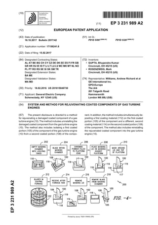
  • 5. EP 3 231 989 A2 5 5 10 15 20 25 30 35 40 45 50 55 and wear interactions between it and the shroud sur- rounding the blade tips 109. The dovetail 102 is also a critical region in that it is subjected to wear and high loads resulting from its engagement with a dovetail slot and the high centrifugal loading generated by the blade 100. [0027] Thus, the turbine blade 100 (or portions thereof) is typically coated with various coatings that are depend- ent on turbine operations and associated temperatures. For example, in particular embodiments, the shank 105 may have been previously coated with a chromium- based material, whereas the airfoil 108 may have been previouslycoatedwithanaluminum-based material. Dur- ing operation, such coatings begin to wear off due to ox- idation and other environmental conditions within the tur- bine engine 10. Thus, the present disclosure is directed to systems and methods for rejuvenating such turbine blades. Though the present disclosure is described in reference to a turbine blade, it should be understood that the coating systems and methods as described herein may be applied to any gas turbine engine component. For example, in certain embodiments, the gas turbine engine components that may be coated according to the present disclosure in addition to the turbine blade may include but are not limited to fan blades, compressor blades, nozzles, shrouds, shroud supports, frames, tur- bine vanes, guide vanes, compressor vanes, or similar. [0028] Referring now to FIG. 3, a schematic view of a kit 110 for rejuvenating such coated components, e.g. the coated turbine blades 100, of the gas turbine engine 10 is illustrated. As shown, the kit 110 includes a first coating material 112 and a second, different coating ma- terial 114. Although the kit 110 is illustrated having two coating materials, it should be understood by those of ordinary skill in the art that any number of coating mate- rials may be used according to the present disclosure. Further, the first and second coating materials 112, 114 may include any suitable coatings, including but not lim- ited to chromium-based coatings, aluminum-based coat- ings, silicon-based coatings, platinum coatings, palladi- um coatings, or any other suitable coating materials. For example, the chromium-based coatings as described herein may include the chromium coating and related chromizing process as described in U.S. Patent Applica- tion Publication No.: 2010/0151124 entitled "Slurry Chr- omizing Process" filed on August 3, 2007, which is incor- porated herein by reference in its entirety. More specifi- cally, in particular embodiments, the coating materials 112, 114 may include aluminide (i.e. Al coating over a Ni, Co, or Fe base alloy), chromide (i.e. Cr coating over Ni, Co, or Fe base alloy), silicide (i.e. silicon coating over Ni, Co, Fe base alloy), Pt-Al (i.e. platinum plating then an aluminide coating), Pd-Al (i.e. palladium plating then an aluminide coating, Hf-Al (i.e. hafniding and aluminid- ing), Cr-Al on one surface with pure chromide or alumi- nide on another surface, Al-Si on one surface with pure Cr or Al on another surface, Al with 5%Si/Cr coating, or any other suitable coatings or combinations thereof. [0029] The kit 110 also includes a maskant 116 for iso- lating a first coated portion of the component from a sec- ond coated portion of the component. More specifically, as shown in the illustrated embodiment, the maskant 116 may include a masking chamber 118. In such an embod- iment, the masking chamber 118 is configured to receive a first coated portion of the component, i.e. the coated shank 105 of the turbine blade 100, so as to isolate the first coated portion from the second coated portion, i.e. the airfoil 108 of the turbine blade 100, which is described in more detail in regards to FIG. 4 below. [0030] Further, asshown, thekit 110 includes acoating system 120 configured to simultaneously deposit the first and second coating materials 112, 114 on the first and second coated portions 105, 108 of the component, re- spectively. For example, in one embodiment, the mask- ing chamber 116 may be filled with the first coating ma- terial 112, e.g. a chromium-based powder. In addition, as shown, the coating system 120 may include a coating furnace 122 configured to apply the second coating ma- terial 114 on the second coated portion 108 of the com- ponent, i.e. the airfoil 108 of the turbine blade 100 as the first coating material is coating the first coated portion of the component. Thus, in such embodiments, the second coating material 114 may include a vapor-based alumi- nide material. [0031] Referring now to FIG. 4, a schematic flow dia- gram of one embodiment of a process 200 for rejuvenat- ing a previously coated turbine blade 100 of the gas tur- bine engine10isillustrated. Asshown at 202,theprocess 200 includes providing an empty masking chamber 118 with optional locating tangs that are configured to engage the tang 104 of shank 105 of the turbine blade 100 so as to retain the turbine blade 100 therein. Thus, as shown at 204, the process 200 includes uninstalling the turbine blade 100 from the engine 10 and placing the coated turbine blade 100 within the masking chamber 118. As shown at 206, the process 200 includes filling the mask- ingchamber 118tothe platform edge with thefirst coating material 112, which as mentioned, may be a chromium- based powder. As shown at 208, the process 200 in- cludesplacinga masking lid 119 on themaskingchamber 118 so as to isolate the airfoil 108 of the turbine blade 100 from the shank 105 of the turbine blade 100. As shown at 210, the process 200 may also optionally in- clude placing an additional maskant 117 (e.g. a maskant film or similar) around the masking lid 119 and the top of the masking chamber 118 so as to further isolate the airfoil 108 of the turbine blade 100 from the shank 105 of the turbine blade 100. Such isolation prevents the first coating material 112 from damaging the airfoil 108 of the turbine blade 100. As shown at 212, the process 200 includes placing the turbine blade 100 (or a plurality of turbine blades 100) in the coating furnace 122. Thus, the method 200 includes simultaneously depositing the first coating material 112ontheshank105of theturbineblade 100 and the second coating material 114 on the airfoil 108 of the turbine blade 100, i.e. via the coating furnace 122. 7 8
  • 6. EP 3 231 989 A2 6 5 10 15 20 25 30 35 40 45 50 55 [0032] More specifically, in certain embodiments, the coating furnace 122 is configured to apply the second coating material 114 via diffusion coating. For typical dif- fusion coating processes, aluminum-based materials (e.g. aluminides), chrome-based materials, and/or sili- con-based materials may be mixed with an activator (e.g. a halide activator) and heated via the coating furnace 122 to form gaseous metal compounds which result in the deposition of the metal on the surface of the part to be coated, i.e. the airfoil 108 of the turbine blade 100. Suitable temperatures for diffusion coating processes may be from about 1500°F (about 815°C) to about 2200°F (about 1205°C), more preferably from about 1900°F (about 1040°C) to about 2100°F (about 1150°C). Further, the turbine blade 100 may remain in the coating furnace 122 for any suitable amount of time during the diffusion coating process depending on a desired thick- ness of the coating. For example, in one embodiment, the turbine blade 100 may remain in the coating furnace from about one (1) hour to about ten (10) hours. In addi- tional embodiments, the turbine blade 100 may remain in the coating furnace 122 for less than one hour or for greater than ten hours. Thus, the gaseous metal com- pounds decompose upon contact with the surfaces of the part, thereby depositing the diffusion coating on the surface thereof. In additional embodiments, the airfoil 108 (or second coated portion of the component) may coated using any other suitable coating techniques in addition to diffusion coating, including but not limited to slurry coating, plating, and/or pack or powder coating. [0033] As shown at 214, the process 200 further in- cludes removing the turbine blade 100 from the coating furnace 122 and allowing the blade 100 to cool. As shown at 216, the masking lid 119 can then be removed from atop the masking chamber 118. As shown at 218, the coated turbine blade 100 is removed from the masking chamber 118. Thus, the previously-coated turbine blade 100 of the present disclosure is rejuvenated using a sin- gle-step coatingprocess(i.e. bothcoatingsaredeposited ontotheblade100indifferent locationsat the same time). [0034] Referring now to FIG. 5, a flow diagram of one embodiment of a method 300 for coating a component of a gas turbine engine 10 is illustrated. As shown at 302, the method 300 includes uninstalling the damaged coat- ed component from the gas turbine engine 10. As men- tioned, the component of the gas turbine engine 10 may include any suitable component such as a turbine blade, a fan blade, a compressor blade, a nozzle, shrouds, shroud supports, frames, a turbine vane, a guide vane, or a compressor vane. [0035] As shown at 304, the method 300 includes iso- lating a first coated portion of the component of the gas turbine engine from a second coated portion of the com- ponent. More specifically, where the coated component is a turbine blade 100, the step of isolating the first coated portion of the blade 100 of the gas turbine engine 10 from the second coated portion of the blade 100 may include placing a shank of the blade 100 in a masking chamber and placing a masking lid on the masking chamber against a platform of an airfoil of the blade so as to isolate the shank from the airfoil. [0036] As shown at 306, the method 300 also includes simultaneously depositing a first coating material on the first coated portion of the component and a different, sec- ond coating material on the second coated portion of the component. In certain embodiments, the step of simul- taneously depositing the first coating material on the first coated portion of the component and the second coating material on the second coated portion of the component may include diffusion coating, plating, slurry coating, powder coating, or any other suitable coating process. As shown at 308, the method 300 includes reinstalling the rejuvenated coated component into the gas turbine engine 10. [0037] Further, the first and second coating materials may include chromium-based coatings, aluminum- based coatings, silicon-based coatings, platinum coat- ings, palladium coatings, or any other suitable coating materials such as those described herein. More specifi- cally, the first coating material may include a chromium- based material, whereas the second coating material may include an aluminum-based material. In such em- bodiments, the step of simultaneously depositing the first coating material on the first coated portion of the com- ponent and the second coating material on the second coated portion of the component may include filling the masking chamber with the chromium-based material be- fore placing the masking lid on the masking chamber so as to coat the shank and depositing the airfoil with the aluminum-based material. [0038] In additional embodiments, the step of depos- iting the airfoil with the aluminum-based material may include placing the turbine blade in a coating furnace and exposing the airfoil to a vapor phase aluminum-based material so as to coat the airfoil, as previously described. [0039] In yet another embodiment, the method 300 may further include removing the turbine blade 100 from the coating furnace, cooling the turbine blade 100 while the shank remains in the masking chamber, removing the masking lidfrom the masking chamber, and removing the shank from the masking chamber. [0040] This written description uses examples to dis- close the invention, including the best mode, and also to enable any person skilled in the art to practice the inven- tion, including making and using any devices or systems and performing any incorporated methods. The patent- able scope of the invention is defined by the claims, and may include other examples that occur to those skilled in the art. Such other examples are intended to be within the scope of the claims if they include structural elements that do not differ from the literal language of the claims, or if they include equivalent structural elements with in- substantial differences from the literal languages of the claims. [0041] Various aspects and embodiments of the present invention are defined by the following numbered 9 10
  • 7. EP 3 231 989 A2 7 5 10 15 20 25 30 35 40 45 50 55 clauses. Any features or elements of any of the aspects or embodiments may be readily combined. 1. Amethodfor rejuvenating adamagedcoatedcom- ponent of a gas turbine engine, the method compris- ing: uninstalling the damaged coated component from the gas turbine engine; isolating a first coated portion of the component of the gas turbine engine from a second coated portion of the component; simultaneously depositing a first coating mate- rial on the first coated portion of the component and a different, second coating material on the second coated portion of the component; and, reinstalling the rejuvenated coated component into the gas turbine engine. 2. The method of clause 1, wherein the coated com- ponent of the gas turbine engine comprises at least one of a turbine blade, a fan blade, a compressor blade, a nozzle, shrouds, shroud supports, frames, a turbine vane, a guide vane, or a compressor vane. 3. The method of clause 1 or 2, wherein simultane- ously depositing the first coating material on the first coated portion of the component and the second coating material on the second coated portion of the component comprises at least one of diffusion coat- ing, plating, slurry coating, or powder coating. 4. The method of any preceding clause, wherein the first coated portion comprises a shank of the turbine blade and the second coated portion comprises an airfoil of the turbine blade. 5. The method of any preceding clause, wherein the shank was previously coated with a chromium- based material and the airfoil was being previously coated with an aluminum-based material. 6. The method of any preceding clause, wherein iso- lating the first coated portion of the component of the gas turbine engine from the second coated portion of the component further comprises: placing the shank in a masking chamber, and placing a masking lid on the masking chamber against a platform of the airfoil so as to isolate the shank from the airfoil. 7. The method of any preceding clause, wherein the first and second coating materials comprise at least one of chromium-based materials, aluminum-based materials, silicon-based materials, platinum materi- als, or palladium materials. 8. The method of any preceding clause, wherein the first coating material comprises a chromium-based material and the second coating material comprises an aluminum-based material. 9. The method of any preceding clause, wherein si- multaneously depositing the first coating material on the first coated portion of the component and the second coating material on the second coated por- tion of the component further comprises: filling the masking chamber with the chromium- based material before placing the masking lid on themasking chamber soastocoat the shank, and depositing the airfoil with the aluminum-based material. 10. The method of any preceding clause, wherein depositing the airfoil with the aluminum-based ma- terial further comprises: placing the turbine blade in a coating furnace, and exposing the airfoil to a vapor phase aluminum- based material so as to coat the airfoil. 11. The method of any preceding clause, further comprising: removing the turbine blade from the coating fur- nace, cooling the turbine blade while the shank re- mains in the masking chamber, removing the masking lid from the masking chamber, removing the shank from the masking chamber, and reinstalling the turbine blade within the gas tur- bine engine. 12. A kit for rejuvenating a damaged coated compo- nent of a gas turbine engine, the kit comprising: a first coating material; a second coating material, the first and second coating materials being different; a maskant for isolating a first coated portion of the component of the gas turbine engine from a second coated portion of the component; and a coating system configured to simultaneously deposit the first and second coating materials on the first and second coated portions of the component, respectively. 13. The kit of clause 12, wherein the maskant com- prises a masking chamber. 11 12
  • 8. EP 3 231 989 A2 8 5 10 15 20 25 30 35 40 45 50 55 14. The kit of clause 12 or 13, wherein the masking chamber is filled with the first coating material, the first coating material comprising a chromium-based powder. 15. The kit of any of clauses 12 to 14, wherein the first and second coating materials comprise at least one of chromium-based coatings, aluminum-based coatings, silicon-based coatings, platinum coatings, or palladium coatings. 16. The kit of any of clauses 12 to 15, wherein the coating system comprises a coating furnace config- ured to apply the second coating material on the sec- ond coated portion of the component, the second coatingmaterialcomprisinganaluminum-basedma- terial. 17. The kit of any of clauses 12 to 16, wherein the coated component of the gas turbine engine com- prises at least one of a turbine blade, a fan blade, a compressor blade, a nozzle, shrouds, shroud sup- ports, frames, a turbine vane, a guidevane, or acom- pressor vane. 18. The kit of any of clauses 12 to 17, wherein simul- taneously depositing thefirst coatingonthefirst coat- ed portion of the component and the second coating on the second coated portion of the component com- prises at least one of diffusion coating, plating, slurry coating, or powder coating. 19. The kit of any of clauses 12 to 18, wherein the first coated portion comprises a shank of the turbine blade and the second coated portion comprises an airfoil of the turbine blade. 20. A method for rejuvenating a damaged coated turbine blade of a gas turbine engine, the method comprising: uninstalling the damaged coated turbine blade from the gas turbine engine; placing a coated shank of the turbine blade in a masking chamber having a masking lid so as to isolate the shank from a coated airfoil of the tur- bine blade; filling a masking chamber with a chromium- based powder coating; and simultaneously depositing an aluminum-based coating on the airfoil via diffusion coating. Claims 1. A method for rejuvenating a damaged coated com- ponent of agas turbine engine(10), themethod com- prising: uninstalling the damaged coated component from the gas turbine engine (10); isolating a first coated portion (105) of the com- ponent of the gas turbine engine (10) from a sec- ond coated portion (108) of the component; simultaneously depositing a first coating mate- rial (112) on the first coated portion (105) of the component and a different, second coating ma- terial (114) on the second coated portion (108) of the component; and, reinstalling the rejuvenated coated component into the gas turbine engine (10). 2. The method of claim 1, wherein the coated compo- nent of thegas turbine engine (10) comprises at least one of a turbine blade (100), a fan blade, a compres- sor blade, a nozzle, shrouds, shroud supports, frames, a turbine vane, a guide vane, or a compres- sor vane. 3. The method of claim 1 or claim 2, wherein simulta- neously depositing the first coating material (112) on the first coated portion (105) of the component and the second coating material (114) on the second coated portion (108) of the component comprises at least one of diffusion coating, plating, slurry coating, or powder coating. 4. The method of claim 2 or claim 3, wherein the first coated portion (105) comprises a shank (105) of the turbine blade (100) and the second coated portion (108) comprises an airfoil (108) of the turbine blade (100). 5. The method of claim 4, wherein the shank (105) was previously coated with a chromium-based material and the airfoil (108) was being previously coatedwith an aluminum-based material. 6. The method of claim 4 or claim 5, wherein isolating the first coated portion (105) of the component of the gas turbine engine (10) from the second coated por- tion (108) of the component further comprises: placing the shank (105) in a masking chamber (118), and placing a masking lid (119) on the masking chamber (118) against a platform (106) of the airfoil (108) so as to isolate the shank (105) from the airfoil (108). 7. The method of any preceding claim, wherein the first and second coating materials (112, 114) comprise at least one of chromium-based materials, alumi- num-based materials, silicon-based materials, plat- inum materials, or palladium materials. 8. The method of claim 7, wherein the first coating ma- 13 14
  • 9. EP 3 231 989 A2 9 5 10 15 20 25 30 35 40 45 50 55 terial (112) comprises a chromium-based material and the second coating material (114) comprises an aluminum-based material. 9. The method of claim 7 or claim 8, wherein simulta- neously depositing the first coating material (112) on the first coated portion (105) of the component and the second coating material (114) on the second coated portion (108) of the component further com- prises: filling the masking chamber (118) with the chro- mium-based material before placing the mask- ing lid (119) on the masking chamber (118) so as to coat the shank (105), and depositing the airfoil (108) with the aluminum- based material. 10. The method of any of claims 7 to 9, wherein depos- iting the airfoil (108) with the aluminum-based ma- terial further comprises: placing the turbine blade (100) in a coating fur- nace (122), and exposing the airfoil (108) to a vapor phase alu- minum-based material so as to coat the airfoil (108). 11. The method of any of claims 7 to 10, further com- prising: removing the turbine blade (100) from the coat- ing furnace (122), cooling the turbine blade (100) while the shank (105) remains in the masking chamber (118), removingthemaskinglid(119)from themasking chamber (118), removing the shank (105) from the masking chamber (118), and reinstalling the turbine blade(100) within the gas turbine engine (10). 12. A kit for rejuvenating a damaged coated component of a gas turbine engine (10), the kit comprising: a first coating material (112); a second coating material (114), the first and second coating materials (112, 114) being dif- ferent; a maskant (116) for isolating a first coated por- tion (105) of the component of the gas turbine engine (10) from a second coated portion (108) of the component; and a coating system (120) configured to simultane- ously deposit the first and second coating ma- terials (112, 114) on the first and second coated portions (105, 108) of the component, respec- tively. 13. The kit of claim 12, wherein the maskant (116) com- prises a masking chamber (118), wherein the mask- ing chamber (118) is filled with the first coating ma- terial (112), the first coating material (112) compris- ing a chromium-based powder. 14. The kit of claim 12 or claim 13, wherein the first and second coating materials (112, 114) comprise at least one of chromium-based coatings, aluminum- based coatings, silicon-based coatings, platinum coatings, or palladium coatings. 15. The kit of any of claims 12 to 14, wherein the coating system (120) comprises acoating furnace (122) con- figured to apply the second coating material (114) on the second coated portion (108) of the compo- nent, the second coating material (114) comprising an aluminum-based material. 15 16
  • 10. EP 3 231 989 A2 10
  • 11. EP 3 231 989 A2 11
  • 12. EP 3 231 989 A2 12
  • 13. EP 3 231 989 A2 13
  • 14. EP 3 231 989 A2 14
  • 15. EP 3 231 989 A2 15 REFERENCES CITED IN THE DESCRIPTION This list of references cited by the applicant is for the reader’s convenience only. It does not form part of the European patent document. Even though great care has been taken in compiling the references, errors or omissions cannot be excluded and the EPO disclaims all liability in this regard. Patent documents cited in the description • US 20100151124 A [0028]