Downloaded 60 times

![Engineering Circuit Analysis, 7th
Edition Chapter Two Solutions 10 March 2006
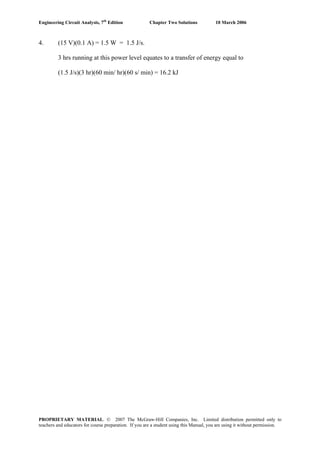
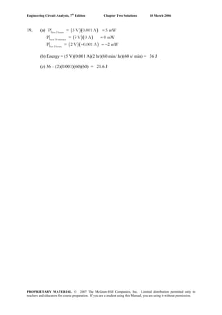
5. Motor power = 175 Hp
(a) With 100% efficient mechanical to electrical power conversion,
(175 Hp)[1 W/ (1/745.7 Hp)] = 130.5 kW
(b) Running for 3 hours,
Energy = (130.5×10³
W)(3 hr)(60 min/hr)(60 s/min) = 1.409 GJ
(c) A single battery has 430 kW-hr capacity. We require
(130.5 kW)(3 hr) = 391.5 kW-hr therefore one battery is sufficient.
PROPRIETARY MATERIAL. © 2007 The McGraw-Hill Companies, Inc. Limited distribution permitted only to
teachers and educators for course preparation. If you are a student using this Manual, you are using it without permission.](https://image.slidesharecdn.com/xgizwmivsiwpds00swny-signature-f172ed6d5ea07afd7eea979324352a9b3640d1cd0448b6e1a174e81551e308e0-poli-140819203045-phpapp01/85/Engineering-circuit-analysis_solutions_7ed_-hayt-5-320.jpg)

![Engineering Circuit Analysis, 7th
Edition Chapter Two Solutions 10 March 2006
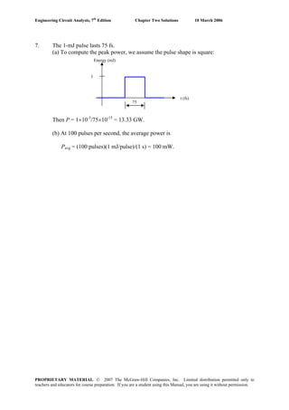
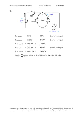
8. The power drawn from the battery is (not quite drawn to scale):
5 7 17 24
P (W)
10
6
t (min)
(a) Total energy (in J) expended is
[6(5) + 0(2) + 0.5(10)(10) + 0.5(10)(7)]60 = 6.9 kJ.
(b) The average power in Btu/hr is
(6900 J/24 min)(60 min/1 hr)(1 Btu/1055 J) = 16.35 Btu/hr.
PROPRIETARY MATERIAL. © 2007 The McGraw-Hill Companies, Inc. Limited distribution permitted only to
teachers and educators for course preparation. If you are a student using this Manual, you are using it without permission.](https://image.slidesharecdn.com/xgizwmivsiwpds00swny-signature-f172ed6d5ea07afd7eea979324352a9b3640d1cd0448b6e1a174e81551e308e0-poli-140819203045-phpapp01/85/Engineering-circuit-analysis_solutions_7ed_-hayt-8-320.jpg)
![Engineering Circuit Analysis, 7th
Edition Chapter Two Solutions 10 March 2006
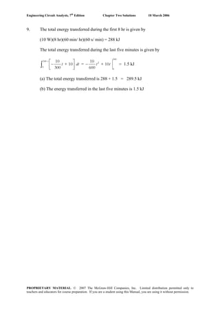
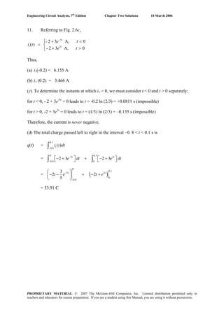
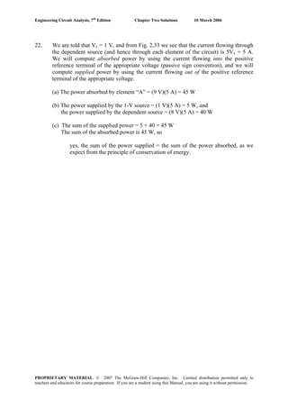
12. Referring to Fig. 2.28,
(a) The average current over one period (10 s) is
iavg = [-4(2) + 2(2) + 6(2) + 0(4)]/10 = 800 mA
(b) The total charge transferred over the interval 1 < t < 12 s is
∫=
12
1
total )( dttiq = -4(1) + 2(2) + 6(2) + 0(4) – 4(2) = 4 C
(c) See Fig. below
2 4 6
8
10 12
16
q (C)
t(s)
-16
8
16
-8
14
PROPRIETARY MATERIAL. © 2007 The McGraw-Hill Companies, Inc. Limited distribution permitted only to
teachers and educators for course preparation. If you are a student using this Manual, you are using it without permission.](https://image.slidesharecdn.com/xgizwmivsiwpds00swny-signature-f172ed6d5ea07afd7eea979324352a9b3640d1cd0448b6e1a174e81551e308e0-poli-140819203045-phpapp01/85/Engineering-circuit-analysis_solutions_7ed_-hayt-12-320.jpg)
![Engineering Circuit Analysis, 7th
Edition Chapter Two Solutions 10 March 2006
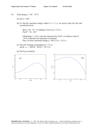
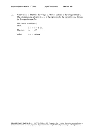
15. (a) Pabs = (+3.2 V)(-2 mA) = –6.4 mW (or +6.4 mW supplied)
(b) Pabs = (+6 V)(-20 A) = –120 W (or +120 W supplied)
(d) Pabs = (+6 V)(2 ix) = (+6 V)[(2)(5 A)] = +60 W
(e) Pabs = (4 sin 1000t V)(-8 cos 1000t mA)| t = 2 ms = +12.11 W
PROPRIETARY MATERIAL. © 2007 The McGraw-Hill Companies, Inc. Limited distribution permitted only to
teachers and educators for course preparation. If you are a student using this Manual, you are using it without permission.](https://image.slidesharecdn.com/xgizwmivsiwpds00swny-signature-f172ed6d5ea07afd7eea979324352a9b3640d1cd0448b6e1a174e81551e308e0-poli-140819203045-phpapp01/85/Engineering-circuit-analysis_solutions_7ed_-hayt-15-320.jpg)
![Engineering Circuit Analysis, 7th
Edition Chapter Two Solutions 10 March 2006
16. i = 3te-100t
mA and v = [6 – 600t] e-100t
mV
(a) The power absorbed at t = 5 ms is
Pabs = ( )[ ] W36006 5
100100
μmst
tt
teet =
−−
⋅−
= 0.01655 μW = 16.55 nW
(b) The energy delivered over the interval 0 < t < ∞ is
( )∫ ∫
∞ ∞
−
−=
0 0
200
J60063 μdtettdtP t
abs
Making use of the relationship
10
!
+
∞
−
=∫ n
axn
a
n
dxex where n is a positive integer and a > 0,
we find the energy delivered to be
= 18/(200)2
- 1800/(200)3
= 0
PROPRIETARY MATERIAL. © 2007 The McGraw-Hill Companies, Inc. Limited distribution permitted only to
teachers and educators for course preparation. If you are a student using this Manual, you are using it without permission.](https://image.slidesharecdn.com/xgizwmivsiwpds00swny-signature-f172ed6d5ea07afd7eea979324352a9b3640d1cd0448b6e1a174e81551e308e0-poli-140819203045-phpapp01/85/Engineering-circuit-analysis_solutions_7ed_-hayt-16-320.jpg)
![Engineering Circuit Analysis, 7th
Edition Chapter Two Solutions 10 March 2006
17. (a) Pabs = (40i)(3e-100t
)| t = 8 ms = [ ]2
8
100
360 mst
t
e =
−
= 72.68 W
(b) Pabs = [ ] W36.34-180-2.0
2
8
100
==⎟
⎠
⎞
⎜
⎝
⎛
=
−
mst
t
ei
dt
di
(c) Pabs = ( )
mst
t
t
eidt
8
100
0
32030
=
−
⎟
⎠
⎞⎜
⎝
⎛ +∫
=
mst
t
t
tt
etdee
8
100
0
100100
60390
=
−′−−
⎟
⎠
⎞⎜
⎝
⎛ +′∫ = 27.63 W
PROPRIETARY MATERIAL. © 2007 The McGraw-Hill Companies, Inc. Limited distribution permitted only to
teachers and educators for course preparation. If you are a student using this Manual, you are using it without permission.](https://image.slidesharecdn.com/xgizwmivsiwpds00swny-signature-f172ed6d5ea07afd7eea979324352a9b3640d1cd0448b6e1a174e81551e308e0-poli-140819203045-phpapp01/85/Engineering-circuit-analysis_solutions_7ed_-hayt-17-320.jpg)
![Engineering Circuit Analysis, 7th
Edition Chapter Two Solutions 10 March 2006
20. Note that in the table below, only the –4-A source and the –3-A source are actually
“absorbing” power; the remaining sources are supplying power to the circuit.
Source Absorbed Power Absorbed Power
2 V source (2 V)(-2 A) - 4 W
8 V source (8 V)(-2 A) - 16 W
-4 A source (10 V)[-(-4 A)] 40 W
10 V source (10 V)(-5 A) - 50 W
-3 A source (10 V)[-(-3 A)] 30 W
The 5 power quantities sum to –4 – 16 + 40 – 50 + 30 = 0, as demanded from
conservation of energy.
PROPRIETARY MATERIAL. © 2007 The McGraw-Hill Companies, Inc. Limited distribution permitted only to
teachers and educators for course preparation. If you are a student using this Manual, you are using it without permission.](https://image.slidesharecdn.com/xgizwmivsiwpds00swny-signature-f172ed6d5ea07afd7eea979324352a9b3640d1cd0448b6e1a174e81551e308e0-poli-140819203045-phpapp01/85/Engineering-circuit-analysis_solutions_7ed_-hayt-20-320.jpg)
![Engineering Circuit Analysis, 7th
Edition Chapter Two Solutions 10 March 2006
29. (a) Pabs = i2
R = [20e-12t
] 2
(1200) μW
= [20e-1.2
] 2
(1200) μW
= 43.54 mW
(b) Pabs = v2
/R = [40 cos 20t] 2
/ 1200 W
keep in mind we
are using radians= [40 cos 2] 2
/ 1200 W
= 230.9 mW
(c) Pabs = v i = 8t 1.5
W
= 253.0 mW
PROPRIETARY MATERIAL. © 2007 The McGraw-Hill Companies, Inc. Limited distribution permitted only to
teachers and educators for course preparation. If you are a student using this Manual, you are using it without permission.](https://image.slidesharecdn.com/xgizwmivsiwpds00swny-signature-f172ed6d5ea07afd7eea979324352a9b3640d1cd0448b6e1a174e81551e308e0-poli-140819203045-phpapp01/85/Engineering-circuit-analysis_solutions_7ed_-hayt-29-320.jpg)
![Engineering Circuit Analysis, 7th
Edition Chapter Two Solutions 10 March 2006
30. It’s probably best to begin this problem by sketching the voltage waveform:
6040
20
t (ms)
v (V)
+10
-10
(a) vmax = +10 V
(b) vavg = [(+10)(20×10-3
) + (-10)(20×10-3
)]/(40×10-3
) = 0
(c) iavg = vavg /R = 0
(d)
R
v
pabs
2
max
max
= = (10)2
/ 50 = 2 W
(e) ⎥
⎦
⎤
⎢
⎣
⎡
⋅
−
+⋅
+
= 20
)10(
20
)10(
40
1 22
RR
p avgabs = 2 W
PROPRIETARY MATERIAL. © 2007 The McGraw-Hill Companies, Inc. Limited distribution permitted only to
teachers and educators for course preparation. If you are a student using this Manual, you are using it without permission.](https://image.slidesharecdn.com/xgizwmivsiwpds00swny-signature-f172ed6d5ea07afd7eea979324352a9b3640d1cd0448b6e1a174e81551e308e0-poli-140819203045-phpapp01/85/Engineering-circuit-analysis_solutions_7ed_-hayt-30-320.jpg)
![Engineering Circuit Analysis, 7th
Edition Chapter Two Solutions 10 March 2006
32. (a)
-1.5 -1 -0.5 0 0.5 1 1.5 2 2.5
-4
-3
-2
-1
0
1
2
3
4
5
6
voltage (V)
current(mA)
(b) We see from our answer to part (a) that this device has a reasonably linear
characteristic (a not unreasonable degree of experimental error is evident in the data).
Thus, we choose to estimate the resistance using the two extreme points:
Reff = [(2.5 – (-1.5)]/[5.23 – (-3.19)] kΩ = 475 Ω
Using the last two points instead, we find Reff = 469 Ω, so that we can state with some
certainty at least that a reasonable estimate of the resistance is approximately 470 Ω.
(c)
-1.5 -1 -0.5 0 0.5 1 1.5 2 2.5
-1.5
-1
-0.5
0
0.5
1
1.5
2
voltage (V)
current(mA)
PROPRIETARY MATERIAL. © 2007 The McGraw-Hill Companies, Inc. Limited distribution permitted only to
teachers and educators for course preparation. If you are a student using this Manual, you are using it without permission.](https://image.slidesharecdn.com/xgizwmivsiwpds00swny-signature-f172ed6d5ea07afd7eea979324352a9b3640d1cd0448b6e1a174e81551e308e0-poli-140819203045-phpapp01/85/Engineering-circuit-analysis_solutions_7ed_-hayt-32-320.jpg)

![Engineering Circuit Analysis, 7th
Edition Chapter Two Solutions 10 March 2006
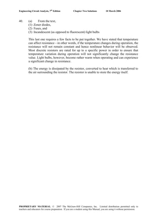
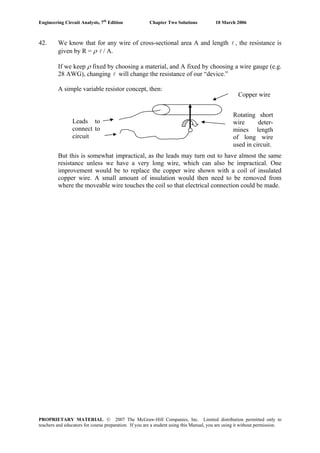
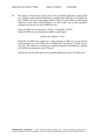
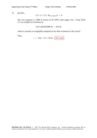
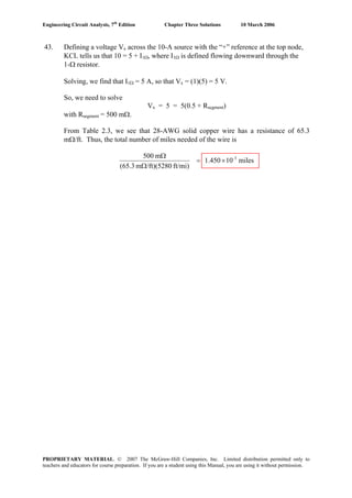
37. We need to create a 470-Ω resistor from 28 AWG wire, knowing that the ambient
temperature is 108o
F, or 42.22o
C.
Referring to Table 2.3, 28 AWG wire is 65.3 mΩ/ft at 20o
C, and using the equation
provided we compute
R2/R1 = (234.5 + T2)/(234.5 + T1) = (234.5 + 42.22)/(234.5 + 20) = 1.087
We thus find that 28 AWG wire is (1.087)(65.3) = 71.0 mΩ/ft.
Thus, to repair the transmitter we will need
(470 Ω)/(71.0 × 10-3 Ω/ft) = 6620 ft (1.25 miles, or 2.02 km).
Note: This seems like a lot of wire to be washing up on shore. We may find we don’t
have enough. In that case, perhaps we should take our cue from Eq. [6], and try to
squash a piece of the wire flat so that it has a very small cross-sectional area…..
PROPRIETARY MATERIAL. © 2007 The McGraw-Hill Companies, Inc. Limited distribution permitted only to
teachers and educators for course preparation. If you are a student using this Manual, you are using it without permission.](https://image.slidesharecdn.com/xgizwmivsiwpds00swny-signature-f172ed6d5ea07afd7eea979324352a9b3640d1cd0448b6e1a174e81551e308e0-poli-140819203045-phpapp01/85/Engineering-circuit-analysis_solutions_7ed_-hayt-37-320.jpg)
![Engineering Circuit Analysis, 7th
Edition Chapter Two Solutions 10 March 2006
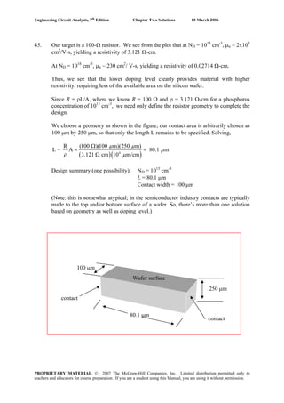
38. We are given that the conductivity σ of copper is 5.8×10⁷
S/m.
(a) 50 ft of #18 (18 AWG) copper wire, which has a diameter of 1.024 mm, will have
a resistance of l/(σ A) ohms, where A = the cross-sectional area and l = 50 ft.
Converting the dimensional quantities to meters,
l = (50 ft)(12 in/ft)(2.54 cm/in)(1 m/100 cm) = 15.24 m
and
r = 0.5(1.024 mm)(1 m/1000 mm) = 5.12×10⁻⁴
m
so that
A = π r2
= π (5.12×10⁻⁴
m)2
= 8.236×10⁻⁷
m2
Thus, R = (15.24 m)/[( 5.8×10⁷
)( 8.236×10⁻⁷
)] = 319.0 mΩ
(b) We assume that the conductivity value specified also holds true at 50o
C.
The cross-sectional area of the foil is
A = (33 μm)(500 μm)(1 m/106
μm)( 1 m/106
μm) = 1.65×10⁻⁸
m2
So that
R = (15 cm)(1 m/100 cm)/[( 5.8×10⁷
)( 1.65×10⁻⁸
)] = 156.7 mΩ
A 3-A current flowing through this copper in the direction specified would
lead to the dissipation of
I2
R = (3)2
(156.7) mW = 1.410 W
PROPRIETARY MATERIAL. © 2007 The McGraw-Hill Companies, Inc. Limited distribution permitted only to
teachers and educators for course preparation. If you are a student using this Manual, you are using it without permission.](https://image.slidesharecdn.com/xgizwmivsiwpds00swny-signature-f172ed6d5ea07afd7eea979324352a9b3640d1cd0448b6e1a174e81551e308e0-poli-140819203045-phpapp01/85/Engineering-circuit-analysis_solutions_7ed_-hayt-38-320.jpg)
![Engineering Circuit Analysis, 7th
Edition Chapter Two Solutions 10 March 2006
43. (a) We need to plot the negative and positive voltage ranges separately, as the positive
voltage range is, after all, exponential!
-0.7 -0.6 -0.5 -0.4 -0.3 -0.2 -0.1 0 0.1
-2
0
2
4
6
8
10
12
14
16
x 10
-6
voltage (V)
current(A)
0 0.01 0.02 0.03 0.04 0.05 0.06 0.07
10
-8
10
-7
10
-6
10
-5
10
-4
voltage (V)
current(A)(b) To determine the resistance of the device at V = 550 mV, we compute the
corresponding current:
I = 10-9
[e39(0.55)
– 1] = 2.068 A
Thus, R(0.55 V) = 0.55/2.068 = 266 mΩ
(c) R = 1 Ω corresponds to V = I. Thus, we need to solve the transcendental equation
I = 10-9
[e39I
– 1]
Using a scientific calculator or the tried-and-true trial and error approach, we find that
I = 514.3 mA
PROPRIETARY MATERIAL. © 2007 The McGraw-Hill Companies, Inc. Limited distribution permitted only to
teachers and educators for course preparation. If you are a student using this Manual, you are using it without permission.](https://image.slidesharecdn.com/xgizwmivsiwpds00swny-signature-f172ed6d5ea07afd7eea979324352a9b3640d1cd0448b6e1a174e81551e308e0-poli-140819203045-phpapp01/85/Engineering-circuit-analysis_solutions_7ed_-hayt-43-320.jpg)
![Engineering Circuit Analysis, 7th
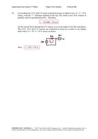
Edition Chapter Three Solutions 10 March 2006
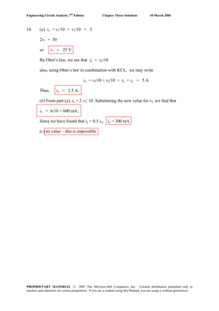
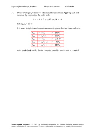
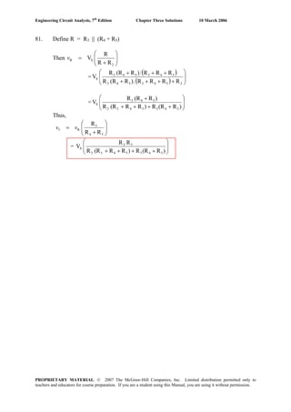
19. Given: (1) Vd = 0 and (2) no current flows into either terminal of Vd.
Calculate Vout by writing two KVL equations.
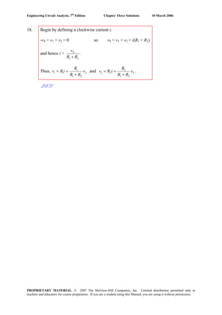
Begin by defining current i1 flowing right through the 100 Ω resistor, and i2 flowing
right through the 470 Ω resistor.
-5 + 100i1 + Vd = 0 [1]
-5 + 100i1 + 470i2 + Vout = 0 [2]
Making use of the fact that in this case Vd = 0, we find that i1 = 5/100 A.
Making use of the fact that no current flows into the input terminals of the op amp,
i1 = i2. Thus, Eq. [2] reduces to
-5 + 570(5/100) + Vout = 0 or
Vout = -23.5 V (hence, the circuit is acting as a voltage amplifier.)
PROPRIETARY MATERIAL. © 2007 The McGraw-Hill Companies, Inc. Limited distribution permitted only to
teachers and educators for course preparation. If you are a student using this Manual, you are using it without permission.](https://image.slidesharecdn.com/xgizwmivsiwpds00swny-signature-f172ed6d5ea07afd7eea979324352a9b3640d1cd0448b6e1a174e81551e308e0-poli-140819203045-phpapp01/85/Engineering-circuit-analysis_solutions_7ed_-hayt-64-320.jpg)
![Engineering Circuit Analysis, 7th
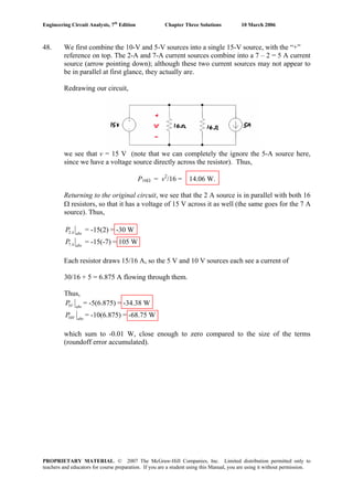
Edition Chapter Three Solutions 10 March 2006
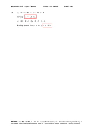
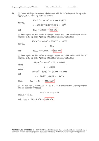
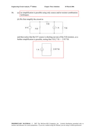
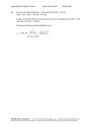
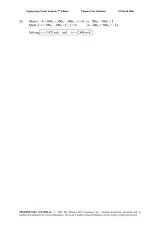
26. (a) We first apply KVL:
-20 + 10i1 + 90 + 40i1 + 2v2 = 0
where v2 = 10i1. Substituting,
70 + 70 i1 = 0
or i1= -1 A.
(b) Applying KVL,
-20 + 10i1 + 90 + 40i1 + 1.5v3 = 0 [1]
where
v3 = -90 – 10i1 + 20 = -70 – 10 i1
alternatively, we could write
v3 = 40i1 + 1.5v3 = -80i1
Using either expression in Eq. [1], we find i1 = 1 A.
(c) Applying KVL,
-20 + 10i1 + 90 + 40i1 - 15 i1 = 0
Solving, i1 = - 2A.
PROPRIETARY MATERIAL. © 2007 The McGraw-Hill Companies, Inc. Limited distribution permitted only to
teachers and educators for course preparation. If you are a student using this Manual, you are using it without permission.](https://image.slidesharecdn.com/xgizwmivsiwpds00swny-signature-f172ed6d5ea07afd7eea979324352a9b3640d1cd0448b6e1a174e81551e308e0-poli-140819203045-phpapp01/85/Engineering-circuit-analysis_solutions_7ed_-hayt-71-320.jpg)
![Engineering Circuit Analysis, 7th
Edition Chapter Three Solutions 10 March 2006
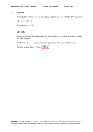
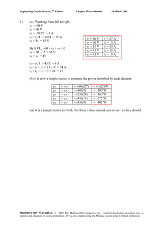
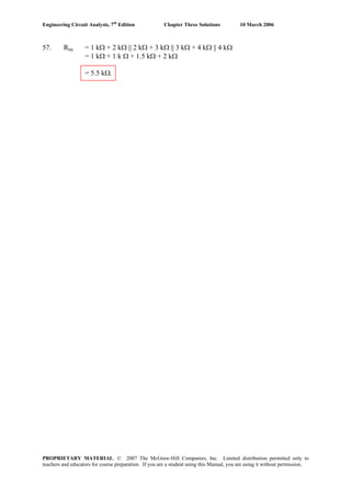
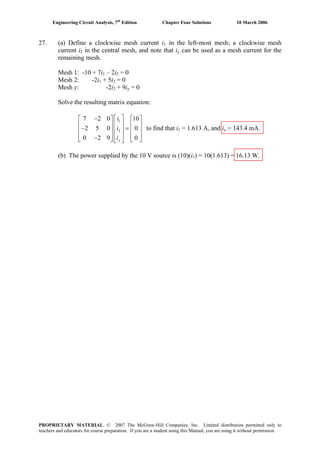
27. Applying KVL, we find that
-20 + 10i1 + 90 + 40i1 + 1.8v3 = 0 [1]
Also, KVL allows us to write
v3 = 40i1 + 1.8v3
v3 = -50i1
So that we may write Eq. [1] as
50i1 – 1.8(50)i1 = -70
or i1 = -70/-40 = 1.75 A.
Since v3 = -50i1 = -87.5 V, no further information is required to determine its value.
The 90-V source is absorbing (90)(i1) = 157.5 W of power and the dependent source
is absorbing (1.8v3)(i1) = -275.6 W of power.
Therefore, none of the conditions specified in (a) to (d) can be met by this circuit.
PROPRIETARY MATERIAL. © 2007 The McGraw-Hill Companies, Inc. Limited distribution permitted only to
teachers and educators for course preparation. If you are a student using this Manual, you are using it without permission.](https://image.slidesharecdn.com/xgizwmivsiwpds00swny-signature-f172ed6d5ea07afd7eea979324352a9b3640d1cd0448b6e1a174e81551e308e0-poli-140819203045-phpapp01/85/Engineering-circuit-analysis_solutions_7ed_-hayt-72-320.jpg)
![Engineering Circuit Analysis, 7th
Edition Chapter Three Solutions 10 March 2006
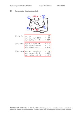
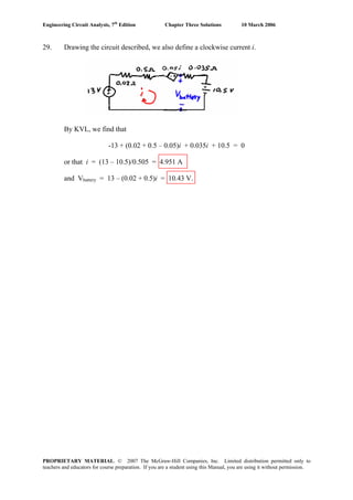
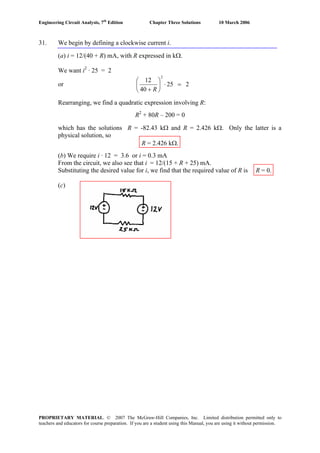
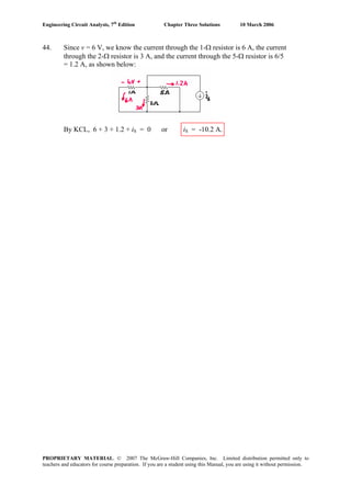
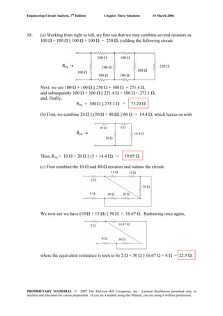
28. (a) Define the charging current i as flowing clockwise in the circuit provided.
By application of KVL,
-13 + 0.02i + Ri + 0.035i + 10.5 = 0
We know that we need a current i = 4 A, so we may calculate the necessary resistance
R = [13 – 10.5 – 0.055(4)]/ 4 = 570 mΩ
(b) The total power delivered to the battery consists of the power absorbed by the
0.035-Ω resistance (0.035i2
), and the power absorbed by the 10.5-V ideal battery
(10.5i). Thus, we need to solve the quadratic equation
0.035i2
+ 10.5i = 25
which has the solutions i = -302.4 A and i = 2.362 A.
In order to determine which of these two values should be used, we must recall that
the idea is to charge the battery, implying that it is absorbing power, or that i as
defined is positive. Thus, we choose i = 2.362 A, and, making use of the expression
developed in part (a), we find that
R = [13 – 10.5 – 0.055(2.362)]/ 2.362 = 1.003 Ω
(c) To obtain a voltage of 11 V across the battery, we apply KVL:
0.035i + 10.5 = 11 so that i = 14.29 A
From part (a), this means we need
R = [13 – 10.5 – 0.055(14.29)]/ 14.29 = 119.9 mΩ
PROPRIETARY MATERIAL. © 2007 The McGraw-Hill Companies, Inc. Limited distribution permitted only to
teachers and educators for course preparation. If you are a student using this Manual, you are using it without permission.](https://image.slidesharecdn.com/xgizwmivsiwpds00swny-signature-f172ed6d5ea07afd7eea979324352a9b3640d1cd0448b6e1a174e81551e308e0-poli-140819203045-phpapp01/85/Engineering-circuit-analysis_solutions_7ed_-hayt-73-320.jpg)
![Engineering Circuit Analysis, 7th
Edition Chapter Three Solutions 10 March 2006
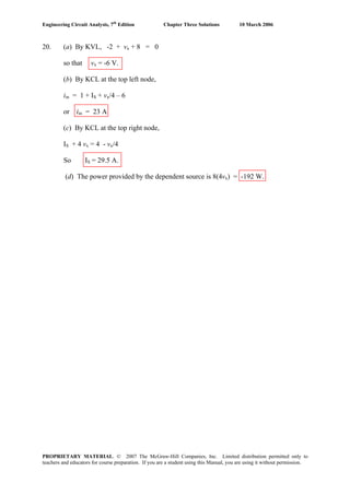
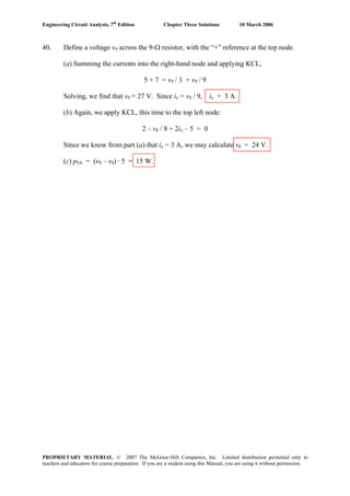
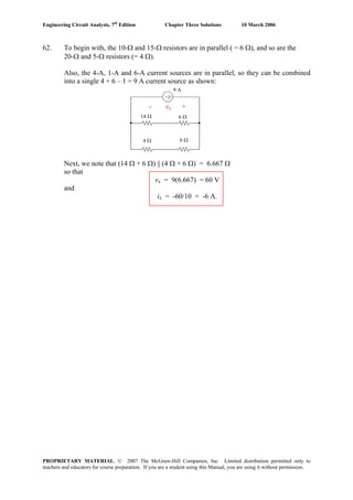
30. Applying KVL about this simple loop circuit (the dependent sources are still linear
elements, by the way, as they depend only upon a sum of voltages)
-40 + (5 + 25 + 20)i – (2v3 + v2) + (4v1 – v2) = 0 [1]
where we have defined i to be flowing in the clockwise direction, and
v1 = 5i, v2 = 25i, and v3 = 20i.
Performing the necessary substition, Eq. [1] becomes
50i - (40i + 25i) + (20i – 25i) = 40
so that i = 40/-20 = -2 A
Computing the absorbed power is now a straightforward matter:
p40V = (40)(-i) = 80 W
p5Ω = 5i2
= 20 W
p25Ω = 25i2
= 100 W
p20Ω = 20i2
= 80 W
pdepsrc1 = (2v3 + v2)(-i) = (40i + 25i) = -260 W
pdepsrc2 = (4v1 - v2)(-i) = (20i - 25i) = -20 W
and we can easily verify that these quantities indeed sum to zero as expected.
PROPRIETARY MATERIAL. © 2007 The McGraw-Hill Companies, Inc. Limited distribution permitted only to
teachers and educators for course preparation. If you are a student using this Manual, you are using it without permission.](https://image.slidesharecdn.com/xgizwmivsiwpds00swny-signature-f172ed6d5ea07afd7eea979324352a9b3640d1cd0448b6e1a174e81551e308e0-poli-140819203045-phpapp01/85/Engineering-circuit-analysis_solutions_7ed_-hayt-75-320.jpg)
![Engineering Circuit Analysis, 7th
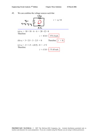
Edition Chapter Three Solutions 10 March 2006
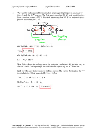
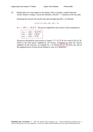
35. Define a voltage vx, “+” reference on the right, across the dependent current source.
Note that in fact vx appears across each of the four elements. We first convert the 10
mS conductance into a 100–Ω resistor, and the 40–mS conductance into a 25–Ω
resistor.
(a) Applying KCL, we sum the currents flowing into the right–hand node:
5 – vx / 100 – vx / 25 + 0.8 ix = 0 [1]
This represents one equation in two unknowns. A second equation to introduce at this
point is
ix = vx /25 so that Eq. [1] becomes
5 – vx / 100 – vx / 25 + 0.8 (vx / 25) = 0
Solving for vx, we find vx = 277.8 V. It is a simple matter now to compute the power
absorbed by each element:
P5A = –5 vx = –1.389 kW
P100Ω = (vx)2
/ 100 = 771.7 W
P25Ω = (vx)2
/ 25 = 3.087 kW
Pdep = –vx(0.8 ix) = –0.8 (vx)2
/ 25 = –2.470 kW
A quick check assures us that the calculated values sum to zero, as they should.
(b) Again summing the currents into the right–hand node,
5 – vx / 100 – vx / 25 + 0.8 iy = 0 [2]
where iy = 5 – vx/100
Thus, Eq. [2] becomes
5 – vx / 100 – vx / 25 + 0.8(5) – 0.8 (iy) / 100 = 0
Solving, we find that vx x = 155.2 V and iy = 3.448 A
So that
P5A = –5 vx = –776.0 W
P100Ω = (vx)2
/ 100 = 240.9 W
P25Ω = (vx)2
/ 25 = 963.5 W
Pdep = –vx(0.8 iy) = –428.1 W
A quick check shows us that the calculated values sum to 0.3, which is reasonably
close to zero compared to the size of the terms (small roundoff errors accumulated).
PROPRIETARY MATERIAL. © 2007 The McGraw-Hill Companies, Inc. Limited distribution permitted only to
teachers and educators for course preparation. If you are a student using this Manual, you are using it without permission.](https://image.slidesharecdn.com/xgizwmivsiwpds00swny-signature-f172ed6d5ea07afd7eea979324352a9b3640d1cd0448b6e1a174e81551e308e0-poli-140819203045-phpapp01/85/Engineering-circuit-analysis_solutions_7ed_-hayt-80-320.jpg)
![Engineering Circuit Analysis, 7th
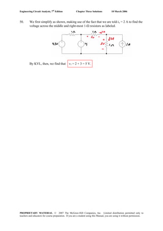
Edition Chapter Three Solutions 10 March 2006
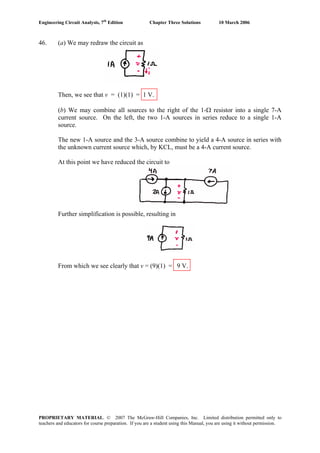
36. Define a voltage v with the “+” reference at the top node. Applying KCL and
summing the currents flowing out of the top node,
v/5,000 + 4×10⁻³
+ 3i1 + v/20,000 = 0 [1]
This, unfortunately, is one equation in two unknowns, necessitating the search for a
second suitable equation. Returning to the circuit diagram, we observe that
i1 = 3 i1 + v/2,000
or i1 = –v/40,000 [2]
Upon substituting Eq. [2] into Eq. [1], Eq. [1] becomes,
v/5,000 + 4×10⁻³
– 3v/40,000 + v/20,000 = 0
Solving, we find that
v = –22.86 V
and
i1 = 571.4 μA
Since ix = i1, we find that ix = 571.4 μA.
PROPRIETARY MATERIAL. © 2007 The McGraw-Hill Companies, Inc. Limited distribution permitted only to
teachers and educators for course preparation. If you are a student using this Manual, you are using it without permission.](https://image.slidesharecdn.com/xgizwmivsiwpds00swny-signature-f172ed6d5ea07afd7eea979324352a9b3640d1cd0448b6e1a174e81551e308e0-poli-140819203045-phpapp01/85/Engineering-circuit-analysis_solutions_7ed_-hayt-81-320.jpg)
![Engineering Circuit Analysis, 7th
Edition Chapter Three Solutions 10 March 2006
39. (a) To cancel out the effects of both the 80-mA and 30-mA sources, iS must be set to
iS = –50 mA.
(b) Define a current is flowing out of the “+” reference terminal of the independent
voltage source. Interpret “no power” to mean “zero power.”
Summing the currents flowing into the top node and invoking KCL, we find that
80×10-3
- 30×10-3
- vS/1×103
+ iS = 0
Simplifying slightly, this becomes
50 - vS + 103
iS = 0 [1]
We are seeking a value for vS such that vS · iS = 0. Clearly, setting vS = 0 will achieve
this. From Eq. [1], we also see that setting vS = 50 V will work as well.
PROPRIETARY MATERIAL. © 2007 The McGraw-Hill Companies, Inc. Limited distribution permitted only to
teachers and educators for course preparation. If you are a student using this Manual, you are using it without permission.](https://image.slidesharecdn.com/xgizwmivsiwpds00swny-signature-f172ed6d5ea07afd7eea979324352a9b3640d1cd0448b6e1a174e81551e308e0-poli-140819203045-phpapp01/85/Engineering-circuit-analysis_solutions_7ed_-hayt-84-320.jpg)
![Engineering Circuit Analysis, 7th
Edition Chapter Three Solutions 10 March 2006
41. Define a voltage vx across the 5-A source, with the “+” reference on top.
Applying KCL at the top node then yields
5 + 5v1 - vx/ (1 + 2) – vx/ 5 = 0 [1]
where v1 = 2[vx /(1 + 2)] = 2 vx / 3.
Thus, Eq. [1] becomes
5 + 5(2 vx / 3) – vx / 3 – vx / 5 = 0
or 75 + 50 vx – 5 vx – 3 vx = 0, which, upon solving, yields vx = -1.786 V.
The power absorbed by the 5-Ω resistor is then simply (vx)2
/5 = 638.0 mW.
PROPRIETARY MATERIAL. © 2007 The McGraw-Hill Companies, Inc. Limited distribution permitted only to
teachers and educators for course preparation. If you are a student using this Manual, you are using it without permission.](https://image.slidesharecdn.com/xgizwmivsiwpds00swny-signature-f172ed6d5ea07afd7eea979324352a9b3640d1cd0448b6e1a174e81551e308e0-poli-140819203045-phpapp01/85/Engineering-circuit-analysis_solutions_7ed_-hayt-86-320.jpg)
![Engineering Circuit Analysis, 7th
Edition Chapter Three Solutions 10 March 2006
54. (a) We see 1Ω || (1 Ω + 1 Ω) || (1 Ω + 1 Ω + 1 Ω)
= 1Ω || 2 Ω || 3 Ω
= 545.5 mΩ
(b) 1/Req = 1 + 1/2 + 1/3 + … + 1/N
Thus, Req = [1 + 1/2 + 1/3 + … + 1/N]-1
PROPRIETARY MATERIAL. © 2007 The McGraw-Hill Companies, Inc. Limited distribution permitted only to
teachers and educators for course preparation. If you are a student using this Manual, you are using it without permission.](https://image.slidesharecdn.com/xgizwmivsiwpds00swny-signature-f172ed6d5ea07afd7eea979324352a9b3640d1cd0448b6e1a174e81551e308e0-poli-140819203045-phpapp01/85/Engineering-circuit-analysis_solutions_7ed_-hayt-99-320.jpg)
![Engineering Circuit Analysis, 7th
Edition Chapter Three Solutions 10 March 2006
59. (a) Req = [(40 Ω + 20 Ω) || 30 Ω + 80 Ω] || 100 Ω + 10 Ω = 60 Ω.
(b) Req = 80 Ω = [(40 Ω + 20 Ω) || 30 Ω + R] || 100 Ω + 10 Ω
70 Ω = [(60 Ω || 30 Ω) + R] || 100 Ω
1/70 = 1/(20 + R) + 0.01
20+ R = 233.3 Ω therefore R = 213.3 Ω.
(c) R = [(40 Ω + 20 Ω) || 30 Ω + R] || 100 Ω + 10 Ω
R – 10 Ω = [20 + R] || 100
1/(R – 10) = 1/(R + 20) + 1/ 100
3000 = R2
+ 10R – 200
Solving, we find R = -61.79 Ω or R = 51.79 Ω.
Clearly, the first is not a physical solution, so R = 51.79 Ω.
PROPRIETARY MATERIAL. © 2007 The McGraw-Hill Companies, Inc. Limited distribution permitted only to
teachers and educators for course preparation. If you are a student using this Manual, you are using it without permission.](https://image.slidesharecdn.com/xgizwmivsiwpds00swny-signature-f172ed6d5ea07afd7eea979324352a9b3640d1cd0448b6e1a174e81551e308e0-poli-140819203045-phpapp01/85/Engineering-circuit-analysis_solutions_7ed_-hayt-104-320.jpg)
![Engineering Circuit Analysis, 7th
Edition Chapter Three Solutions 10 March 2006
60. (a) 25 Ω = 100 Ω || 100 Ω || 100 Ω || 100 Ω
(b) 60 Ω = [(100 Ω || 100 Ω) + 100 Ω] || 100 Ω
(c) 40 Ω = (100 Ω + 100 Ω) || 100 Ω || 100 Ω
PROPRIETARY MATERIAL. © 2007 The McGraw-Hill Companies, Inc. Limited distribution permitted only to
teachers and educators for course preparation. If you are a student using this Manual, you are using it without permission.](https://image.slidesharecdn.com/xgizwmivsiwpds00swny-signature-f172ed6d5ea07afd7eea979324352a9b3640d1cd0448b6e1a174e81551e308e0-poli-140819203045-phpapp01/85/Engineering-circuit-analysis_solutions_7ed_-hayt-105-320.jpg)
![Engineering Circuit Analysis, 7th
Edition Chapter Three Solutions 10 March 2006
61. Req = [(5 Ω || 20 Ω) + 6 Ω] || 30 Ω + 2.5 Ω = 10 Ω
The source therefore provides a total of 1000 W and a current of 100/10 = 10 A.
P2.5Ω = (10)2
· 2.5 = 250 W
V30Ω = 100 - 2.5(10) = 75 V
P30Ω = 752
/ 30 = 187.5 W
I6Ω = 10 – V30Ω /30 = 10 – 75/30 = 7.5 A
P6Ω = (7.5)2
· 6 = 337.5 W
V5Ω = 75 – 6(7.5) = 30 V
P5Ω = 302
/ 5 = 180 W
V20Ω = V5Ω = 30 V
P20Ω = 302
/20 = 45 W
We check our results by verifying that the absorbed powers in fact add to 1000 W.
PROPRIETARY MATERIAL. © 2007 The McGraw-Hill Companies, Inc. Limited distribution permitted only to
teachers and educators for course preparation. If you are a student using this Manual, you are using it without permission.](https://image.slidesharecdn.com/xgizwmivsiwpds00swny-signature-f172ed6d5ea07afd7eea979324352a9b3640d1cd0448b6e1a174e81551e308e0-poli-140819203045-phpapp01/85/Engineering-circuit-analysis_solutions_7ed_-hayt-106-320.jpg)
![Engineering Circuit Analysis, 7th
Edition Chapter Three Solutions 10 March 2006
PROPRIETARY MATERIAL. © 2007 The McGraw-Hill Companies, Inc. Limited distribution permitted only to
teachers and educators for course preparation. If you are a student using this Manual, you are using it without permission.
63. (a) Working from right to left, and borrowing x || y notation from resistance
calculations to indicate the operation xy/(x + y),
Gin = {[(6 || 2 || 3) + 0.5] || 1.5 || 2.5 + 0.8} || 4 || 5 mS
= {[(1) + 0.5] || 1.5 || 2.5 + 0.8} || 4 || 5 mS
13.64 mS
100 mS
22.22 mS
Gin →
= {1.377} || 4 || 5
= 0.8502 mS = 850.2 mS
(b) The 50-mS and 40-mS conductances are in series, equivalent to (50(40)/90 =
22.22 mS. The 30-mS and 25-mS conductances are also in series, equivalent to 13.64
mS. Redrawing for clarity,
we see that Gin = 10 + 22.22 + 13.64 = 135.9 mS.](https://image.slidesharecdn.com/xgizwmivsiwpds00swny-signature-f172ed6d5ea07afd7eea979324352a9b3640d1cd0448b6e1a174e81551e308e0-poli-140819203045-phpapp01/85/Engineering-circuit-analysis_solutions_7ed_-hayt-108-320.jpg)
![Engineering Circuit Analysis, 7th
Edition Chapter Three Solutions 10 March 2006
65. With the meter being a short circuit and no current flowing through it, we can write
R1i1 = R2i2
R3i3 = RiR
And since i1 = i3, and i2 = iR, Eq [1] becomes 1 2
3
R R
R R
= , or 3
2
1
R
R R
R
= . Q.E.D.
→ 1 1 2 2
3 3 R
R i R i
R i Ri
= [1]
PROPRIETARY MATERIAL. © 2007 The McGraw-Hill Companies, Inc. Limited distribution permitted only to
teachers and educators for course preparation. If you are a student using this Manual, you are using it without permission.](https://image.slidesharecdn.com/xgizwmivsiwpds00swny-signature-f172ed6d5ea07afd7eea979324352a9b3640d1cd0448b6e1a174e81551e308e0-poli-140819203045-phpapp01/85/Engineering-circuit-analysis_solutions_7ed_-hayt-110-320.jpg)

![Engineering Circuit Analysis, 7th
Edition Chapter Three Solutions 10 March 2006
72. p15Ω = (v15)2
/ 15×103
A
v15 = 15×103
(-0.3 v1)
where v1 = [4 (5)/ (5 + 2)] · 2 = 5.714 V
Therefore v15 = -25714 V and p15 = 44.08 kW.
PROPRIETARY MATERIAL. © 2007 The McGraw-Hill Companies, Inc. Limited distribution permitted only to
teachers and educators for course preparation. If you are a student using this Manual, you are using it without permission.](https://image.slidesharecdn.com/xgizwmivsiwpds00swny-signature-f172ed6d5ea07afd7eea979324352a9b3640d1cd0448b6e1a174e81551e308e0-poli-140819203045-phpapp01/85/Engineering-circuit-analysis_solutions_7ed_-hayt-117-320.jpg)
![Engineering Circuit Analysis, 7th
Edition Chapter Three Solutions 10 March 2006
75. The controlling voltage v1, needed to obtain the power into the 47-kΩ resistor, can be
found separately as that network does not depend on the left-hand network.
The right-most 2 kΩ resistor can be neglected.
By current division, then, in combination with Ohm’s law,
v1 = 3000[5×10⁻³
(2000)/ (2000 + 3000 + 7000)] = 2.5 V
Voltage division gives the voltage across the 47-kΩ resistor:
V0.9228
16.6747
7)0.5(2.5)(4
20||10047
47
5.0 1 =
+
=
+
v
So that p47kΩ = (0.9928)2
/ 47×103
= 18.12 μW
PROPRIETARY MATERIAL. © 2007 The McGraw-Hill Companies, Inc. Limited distribution permitted only to
teachers and educators for course preparation. If you are a student using this Manual, you are using it without permission.](https://image.slidesharecdn.com/xgizwmivsiwpds00swny-signature-f172ed6d5ea07afd7eea979324352a9b3640d1cd0448b6e1a174e81551e308e0-poli-140819203045-phpapp01/85/Engineering-circuit-analysis_solutions_7ed_-hayt-120-320.jpg)
![Engineering Circuit Analysis, 7th
Edition Chapter Three Solutions 10 March 2006
77. (a)
)]R(R||[RR
)R(R||R
V
4321
432
S2
++
+
=v
=
( )
( )4324321
432432
S
RRR)R(RRR
RRR)R(RR
V
++++
+++
=
( ) )R(RRRRRR
)R(RR
V
4324321
432
S
++++
+
(b)
)]R(R||[RR
R
V
4321
1
S1
++
=v
=
( )4324321
1
S
RRR)R(RRR
R
V
++++
=
( ) )R(RRRRRR
)RR(RR
V
4324321
4321
S
++++
++
(c) ⎟⎟
⎠
⎞
⎜⎜
⎝
⎛
++⎟⎟
⎠
⎞
⎜⎜
⎝
⎛
=
432
2
1
1
4
RRR
R
R
v
i
=
( )
[ ])RR)(RR(RR)RR(RRR
RRRRR
V
43243243211
24321
S
++++++
++
=
( ) )R(RRRRRR
R
V
4324321
2
S
++++
PROPRIETARY MATERIAL. © 2007 The McGraw-Hill Companies, Inc. Limited distribution permitted only to
teachers and educators for course preparation. If you are a student using this Manual, you are using it without permission.](https://image.slidesharecdn.com/xgizwmivsiwpds00swny-signature-f172ed6d5ea07afd7eea979324352a9b3640d1cd0448b6e1a174e81551e308e0-poli-140819203045-phpapp01/85/Engineering-circuit-analysis_solutions_7ed_-hayt-122-320.jpg)
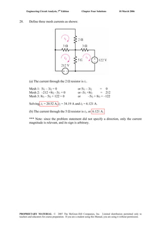
![Engineering Circuit Analysis, 7th
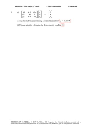
Edition Chapter Four Solutions 10 March 2006
5. We begin by selecting the bottom node as the reference terminal, and defining
two nodal voltages VA and VB, as shown. (Note if we choose the upper right
node, v1 becomes a nodal voltage and falls directly out of the solution.)
VA VB
Ref.
We note that after completing nodal analysis, we can find v1 as v1 = VA – VB.
At node A: A AV V VB
10 5
4
−
= + [1]
At node B: B BV V V
( 6)
8 5
A−
− − = + [2]
Simplifying, 3VA – 2VB = 40 [1]
–8VA + 13VB = 240 [2]
Solving, VA = 43.48 V and VB = 45.22 V, so v1 = –1.740 V.
PROPRIETARY MATERIAL. © 2007 The McGraw-Hill Companies, Inc. Limited distribution permitted only to
teachers and educators for course preparation. If you are a student using this Manual, you are using it without permission.](https://image.slidesharecdn.com/xgizwmivsiwpds00swny-signature-f172ed6d5ea07afd7eea979324352a9b3640d1cd0448b6e1a174e81551e308e0-poli-140819203045-phpapp01/85/Engineering-circuit-analysis_solutions_7ed_-hayt-134-320.jpg)
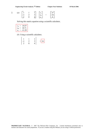
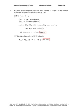
![Engineering Circuit Analysis, 7th
Edition Chapter Four Solutions 10 March 2006
6. By inspection, no current flows through the 2 Ω resistor, so i1 = 0.
We next designate the bottom node as the reference terminal, and define VA and
VB as shown:
VA VB
Ref.
At node A: A A BV V V
2 [1]
3 1
−
= +
At node B: B B B AV V V V
2 [
6 6 1
2]
−
− = + +
Note this yields VA and VB, not v1, due to our choice of reference node. So, we
obtain v1 by KVL: v1 = VA – VB.
Simplifying Eqs. [1] and [2],
4VA – 3VB = 6 [1]
–3VA + 4VB = –6 [2]
Solving, VA = 0.8571 V and VB = -0.8571 V, so v1 = 1.714 V.
PROPRIETARY MATERIAL. © 2007 The McGraw-Hill Companies, Inc. Limited distribution permitted only to
teachers and educators for course preparation. If you are a student using this Manual, you are using it without permission.](https://image.slidesharecdn.com/xgizwmivsiwpds00swny-signature-f172ed6d5ea07afd7eea979324352a9b3640d1cd0448b6e1a174e81551e308e0-poli-140819203045-phpapp01/85/Engineering-circuit-analysis_solutions_7ed_-hayt-135-320.jpg)
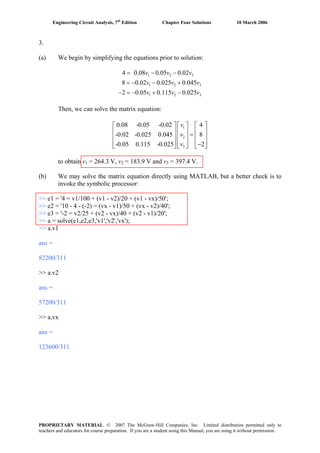
![Engineering Circuit Analysis, 7th
Edition Chapter Four Solutions 10 March 2006
7. The bottom node has the largest number of branch connections, so we choose that as
our reference node. This also makes vP easier to find, as it will be a nodal voltage.
Working from left to right, we name our nodes 1, P, 2, and 3.
NODE 1: 10 = v1/ 20 + (v1 – vP)/ 40 [1]
NODE P: 0 = (vP – v1)/ 40 + vP/ 100 + (vP – v2)/ 50 [2]
NODE 2: -2.5 + 2 = (v2 – vP)/ 50 + (v2 – v3)/ 10 [3]
NODE 3: 5 – 2 = v3/ 200 + (v3 – v2)/ 10 [4]
Simplifying,
60v1 - 20vP = 8000 [1]
-50v1 + 110 vP - 40v2 = 0 [2]
- vP + 6v2 - 5v3 = -25 [3]
-200v2 + 210v3 = 6000 [4]
Solving,
vP = 171.6 V
PROPRIETARY MATERIAL. © 2007 The McGraw-Hill Companies, Inc. Limited distribution permitted only to
teachers and educators for course preparation. If you are a student using this Manual, you are using it without permission.](https://image.slidesharecdn.com/xgizwmivsiwpds00swny-signature-f172ed6d5ea07afd7eea979324352a9b3640d1cd0448b6e1a174e81551e308e0-poli-140819203045-phpapp01/85/Engineering-circuit-analysis_solutions_7ed_-hayt-136-320.jpg)
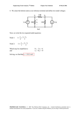
![Engineering Circuit Analysis, 7th
Edition Chapter Four Solutions 10 March 2006
8. The logical choice for a reference node is the bottom node, as then vx will
automatically become a nodal voltage.
NODE 1: 4 = v1/ 100 + (v1 – v2)/ 20 + (v1 – vx)/ 50 [1]
NODE x: 10 – 4 – (-2) = (vx – v1)/ 50 + (vx – v2)/ 40 [2]
NODE 2: -2 = v2 / 25 + (v2 – vx)/ 40 + (v2 – v1)/ 20 [3]
Simplifying,
4 = 0.0800v1 – 0.0500v2 – 0.0200vx [1]
8 = -0.0200v1 – 0.02500v2 + 0.04500vx [2]
-2 = -0.0500v1 + 0.1150v2 – 0.02500vx [3]
Solving,
vx = 397.4 V.
PROPRIETARY MATERIAL. © 2007 The McGraw-Hill Companies, Inc. Limited distribution permitted only to
teachers and educators for course preparation. If you are a student using this Manual, you are using it without permission.](https://image.slidesharecdn.com/xgizwmivsiwpds00swny-signature-f172ed6d5ea07afd7eea979324352a9b3640d1cd0448b6e1a174e81551e308e0-poli-140819203045-phpapp01/85/Engineering-circuit-analysis_solutions_7ed_-hayt-137-320.jpg)
![Engineering Circuit Analysis, 7th
Edition Chapter Four Solutions 10 March 2006
9. Designate the node between the 3-Ω and 6-Ω resistors as node X, and the right-hand
node of the 6-Ω resistor as node Y. The bottom node is chosen as the reference node.
(a) Writing the two nodal equations, then
NODE X: –10 = (vX – 240)/ 3 + (vX – vY)/ 6 [1]
NODE Y: 0 = (vY – vX)/ 6 + vY/ 30 + (vY – 60)/ 12 [2]
Simplifying, -180 + 1440 = 9 vX – 3 vY [1]
10800 = - 360 vX + 612 vY [2]
Solving, vX = 181.5 V and vY = 124.4 V
Thus, v1 = 240 – vX = 58.50 V and v2 = vY – 60 = 64.40 V
(b) The power absorbed by the 6-Ω resistor is
(vX – vY)2
/ 6 = 543.4 W
PROPRIETARY MATERIAL. © 2007 The McGraw-Hill Companies, Inc. Limited distribution permitted only to
teachers and educators for course preparation. If you are a student using this Manual, you are using it without permission.](https://image.slidesharecdn.com/xgizwmivsiwpds00swny-signature-f172ed6d5ea07afd7eea979324352a9b3640d1cd0448b6e1a174e81551e308e0-poli-140819203045-phpapp01/85/Engineering-circuit-analysis_solutions_7ed_-hayt-138-320.jpg)
![Engineering Circuit Analysis, 7th
Edition Chapter Four Solutions 10 March 2006
10. Only one nodal equation is required: At the node where three resistors join,
0.02v1 = (vx – 5 i2) / 45 + (vx – 100) / 30 + (vx – 0.2 v3) / 50 [1]
This, however, is one equation in four unknowns, the other three resulting from the
presence of the dependent sources. Thus, we require three additional equations:
i2 = (0.2 v3 - vx) / 50 [2]
v1 = 0.2 v3 - 100 [3]
v3 = 50i2 [4]
Simplifying,
v1 – 0.2v3 = -100 [3]
– v3 + 50 i2 = 0 [4]
–vx + 0.2v3 – 50 i2 = 0 [2]
0.07556vx – 0.02v1 – 0.004v3 – 0.111i2 = 33.33 [1]
Solving, we find that v1 = -103..8 V and i2 = -377.4 mA.
PROPRIETARY MATERIAL. © 2007 The McGraw-Hill Companies, Inc. Limited distribution permitted only to
teachers and educators for course preparation. If you are a student using this Manual, you are using it without permission.](https://image.slidesharecdn.com/xgizwmivsiwpds00swny-signature-f172ed6d5ea07afd7eea979324352a9b3640d1cd0448b6e1a174e81551e308e0-poli-140819203045-phpapp01/85/Engineering-circuit-analysis_solutions_7ed_-hayt-139-320.jpg)
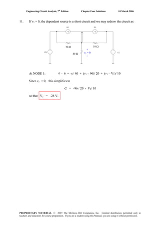
![Engineering Circuit Analysis, 7th
Edition Chapter Four Solutions 10 March 2006
12. We choose the bottom node as ground to make calculation of i5 easier. The left-most
node is named “1”, the top node is named “2”, the central node is named “3” and the
node between the 4-Ω and 6-Ω resistors is named “4.”
NODE 1: - 3 = v1/2 + (v1 – v2)/ 1 [1]
NODE 2: 2 = (v2 – v1)/ 1 + (v2 – v3)/ 3 + (v2 – v4)/ 4 [2]
NODE 3: 3 = v3/ 5 + (v3 – v4)/ 7 + (v3 – v2)/ 3 [3]
NODE 4: 0 = v4/ 6 + (v4 – v3)/ 7 + (v4 – v2)/ 4 [4]
Rearranging and grouping terms,
3v1 – 2v2 = -6 [1]
-12v1 + 19v2 – 4v3 – 3v4 = 24 [2]
–35v2 + 71v3 – 15v4 = 315 [3]
-42v2 – 24v3 + 94v4 = 0 [4]
Solving, we find that v3 = 6.760 V and so i5 = v3/ 5 = 1.352 A.
PROPRIETARY MATERIAL. © 2007 The McGraw-Hill Companies, Inc. Limited distribution permitted only to
teachers and educators for course preparation. If you are a student using this Manual, you are using it without permission.](https://image.slidesharecdn.com/xgizwmivsiwpds00swny-signature-f172ed6d5ea07afd7eea979324352a9b3640d1cd0448b6e1a174e81551e308e0-poli-140819203045-phpapp01/85/Engineering-circuit-analysis_solutions_7ed_-hayt-141-320.jpg)
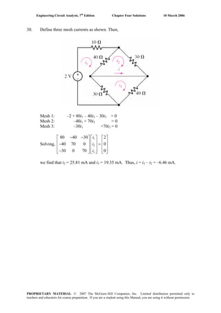
![Engineering Circuit Analysis, 7th
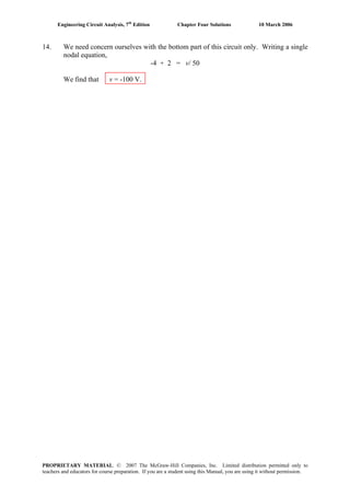
Edition Chapter Four Solutions 10 March 2006
13. We can redraw this circuit and eliminate the 2.2-kΩ resistor as no current flows
through it:
At NODE 2: 7×10⁻³
– 5×10-3
= (v2 + 9)/ 470 + (v2 – vx)/ 10×10-3
[1]
At NODE x: 5×10⁻³
– 0.2v1 = (vx – v2)/ 10×103
[2]
The additional equation required by the presence of the dependent source and the fact
that its controlling variable is not one of the nodal voltages:
v1 = v2 – vx [3]
Eliminating the variable v1 and grouping terms, we obtain:
10,470 v2 – 470 vx = –89,518
and
1999 v2 – 1999 vx = 50
Solving, we find vx = –8.086 V.
↓9 V 7 mA
5 mA
0.2 v1
10 kΩ
470 Ω + v1 - vx
v2
PROPRIETARY MATERIAL. © 2007 The McGraw-Hill Companies, Inc. Limited distribution permitted only to
teachers and educators for course preparation. If you are a student using this Manual, you are using it without permission.](https://image.slidesharecdn.com/xgizwmivsiwpds00swny-signature-f172ed6d5ea07afd7eea979324352a9b3640d1cd0448b6e1a174e81551e308e0-poli-140819203045-phpapp01/85/Engineering-circuit-analysis_solutions_7ed_-hayt-142-320.jpg)
![Engineering Circuit Analysis, 7th
Edition Chapter Four Solutions 10 March 2006
15. We choose the bottom node as the reference terminal. Then:
Node 1: 1 1
2
2 1
v v v− 2
+− = [1]
Node 2: 2 32 1 2 4
4
1 2 4
v vv v v v−− −
= + + [2]
Node 3: 3 2 3 3 4
2 [3]
2 5 10
v v v v v− −
= + +
Node 4: 4 34 4 2
6 10 4
v vv v v−
0
−
= + + [4]
Node 5: 5 5 7
1
2 1
v v v−
− = [5]+
Node 6: 6 6 7 6 8
5 2 10
v v v v v− −
= + +1 [6]
Node 7: 7 5 7 6 7 8
2 [7]
1 2 4
v v v v v v− − −
= + +
Node 8: 8 8 6 8 7
6 10 4
v v v v v− −
= + +0 [8]
Note that Eqs. [1-4] may be solved independently of Eqs. [5-8].
Simplifying,
to yield
1 2
1 2 3 4
2 3 4
2 3 4
3 2 4 [1]
4 7 2 16 [2]
5 8 20 [3]
15 6 31 0 [4]
v v
v v v v
v v v
v v v
− = −
− + − − =
− + − =
− − + =
1
2
3
4
3.370 V
7.055 V
7.518 V
4.869 V
v
v
v
v
=
=
=
=
and
5 7
6 7 8
5 6 7 8
6 7 8
3 2 2 [5]
8 5 10 [6]
4 2 7 8 [7]
6 15 31 0 [8]
v v
v v v
v v v v
v v v
− = −
− − =
− − + − =
− − + =
to yield
5
6
7
8
1.685 V
3.759 V
3.527 V
2.434 V
v
v
v
v
=
=
=
=
PROPRIETARY MATERIAL. © 2007 The McGraw-Hill Companies, Inc. Limited distribution permitted only to
teachers and educators for course preparation. If you are a student using this Manual, you are using it without permission.](https://image.slidesharecdn.com/xgizwmivsiwpds00swny-signature-f172ed6d5ea07afd7eea979324352a9b3640d1cd0448b6e1a174e81551e308e0-poli-140819203045-phpapp01/85/Engineering-circuit-analysis_solutions_7ed_-hayt-144-320.jpg)
![Engineering Circuit Analysis, 7th
Edition Chapter Four Solutions 10 March 2006
16. We choose the center node for our common terminal, since it connects to the largest
number of branches. We name the left node “A”, the top node “B”, the right node
“C”, and the bottom node “D”. We next form a supernode between nodes A and B.
At the supernode: 5 = (VA – VD)/ 10 + VA/ 20 + (VB – VC)/ 12.5 [1]
At node C: VC = 150 [2]
At node D: -10 = VD/ 25 + (VD – VA)/ 10 [3]
Our supernode-related equation is VB – VA = 100 [4]
Simplifiying and grouping terms,
0.15 VA + 0.08 VB - 0.08 VC – 0.1 VD = 5 [1]
VC = 150 [2]
-25 VA + 35 VD = -2500 [3]
- VA + VB = 100 [4]
Solving, we find that VD = -63.06 V. Since v4 = - VD,
v4 = 63.06 V.
PROPRIETARY MATERIAL. © 2007 The McGraw-Hill Companies, Inc. Limited distribution permitted only to
teachers and educators for course preparation. If you are a student using this Manual, you are using it without permission.](https://image.slidesharecdn.com/xgizwmivsiwpds00swny-signature-f172ed6d5ea07afd7eea979324352a9b3640d1cd0448b6e1a174e81551e308e0-poli-140819203045-phpapp01/85/Engineering-circuit-analysis_solutions_7ed_-hayt-145-320.jpg)
![Engineering Circuit Analysis, 7th
Edition Chapter Four Solutions 10 March 2006
17. Choosing the bottom node as the reference terminal and naming the left node “1”, the
center node “2” and the right node “3”, we next form a supernode about nodes 1 and
2, encompassing the dependent voltage source.
At the supernode, 5 – 8 = (v1 – v2)/ 2 + v3/ 2.5 [1]
At node 2, 8 = v2 / 5 + (v2 – v1)/ 2 [2]
Our supernode equation is v1 - v3 = 0.8 vA [3]
Since vA = v2, we can rewrite [3] as v1 – v3 = 0.8v2
Simplifying and collecting terms,
0.5 v1 - 0.5 v2 + 0.4 v3 = -3 [1]
-0.5 v1 + 0.7 v2 = 8 [2]
v1 - 0.8 v2 - v3 = 0 [3]
(a) Solving for v2 = vA, we find that vA = 25.91 V
(b) The power absorbed by the 2.5-Ω resistor is
(v3)2
/ 2.5 = (-0.4546)2
/ 2.5 = 82.66 mW.
PROPRIETARY MATERIAL. © 2007 The McGraw-Hill Companies, Inc. Limited distribution permitted only to
teachers and educators for course preparation. If you are a student using this Manual, you are using it without permission.](https://image.slidesharecdn.com/xgizwmivsiwpds00swny-signature-f172ed6d5ea07afd7eea979324352a9b3640d1cd0448b6e1a174e81551e308e0-poli-140819203045-phpapp01/85/Engineering-circuit-analysis_solutions_7ed_-hayt-146-320.jpg)
![Engineering Circuit Analysis, 7th
Edition Chapter Four Solutions 10 March 2006
18. Selecting the bottom node as the reference terminal, we name the left node “1”, the
middle node “2” and the right node “3.”
NODE 1: 5 = (v1 – v2)/ 20 + (v1 – v3)/ 50 [1]
NODE 2: v2 = 0.4 v1 [2]
NODE 3: 0.01 v1 = (v3 – v2)/ 30 + (v3 – v1)/ 50 [3]
Simplifying and collecting terms, we obtain
0.07 v1 – 0.05 v2 – 0.02 v3 = 5 [1]
0.4 v1 – v2 = 0 [2]
-0.03 v1 – 0.03333 v2 + 0.05333 v3 = 0 [3]
Since our choice of reference terminal makes the controlling variable of both
dependent sources a nodal voltage, we have no need for an additional equation as we
might have expected.
Solving, we find that v1 = 148.2 V, v2 = 59.26 V, and v3 = 120.4 V.
The power supplied by the dependent current source is therefore
(0.01 v1) • v3 = 177.4 W.
PROPRIETARY MATERIAL. © 2007 The McGraw-Hill Companies, Inc. Limited distribution permitted only to
teachers and educators for course preparation. If you are a student using this Manual, you are using it without permission.](https://image.slidesharecdn.com/xgizwmivsiwpds00swny-signature-f172ed6d5ea07afd7eea979324352a9b3640d1cd0448b6e1a174e81551e308e0-poli-140819203045-phpapp01/85/Engineering-circuit-analysis_solutions_7ed_-hayt-147-320.jpg)
![Engineering Circuit Analysis, 7th
Edition Chapter Four Solutions 10 March 2006
19. At node x: vx/ 4 + (vx – vy)/ 2 + (vx – 6)/ 1 = 0 [1]
At node y: (vy – kvx)/ 3 + (vy – vx)/ 2 = 2 [2]
Our additional constraint is that vy = 0, so we may simplify Eqs. [1] and [2]:
14 vx = 48 [1]
-2k vx - 3 vx = 12 [2]
Since Eq. [1] yields vx = 48/14 = 3.429 V, we find that
k = (12 + 3 vx)/ (-2 vx) = -3.250
PROPRIETARY MATERIAL. © 2007 The McGraw-Hill Companies, Inc. Limited distribution permitted only to
teachers and educators for course preparation. If you are a student using this Manual, you are using it without permission.](https://image.slidesharecdn.com/xgizwmivsiwpds00swny-signature-f172ed6d5ea07afd7eea979324352a9b3640d1cd0448b6e1a174e81551e308e0-poli-140819203045-phpapp01/85/Engineering-circuit-analysis_solutions_7ed_-hayt-148-320.jpg)
![Engineering Circuit Analysis, 7th
Edition Chapter Four Solutions 10 March 2006
20. Choosing the bottom node joining the 4-Ω resistor, the 2-A current sourcee and the
4-V voltage source as our reference node, we next name the other node of the 4-Ω
resistor node “1”, and the node joining the 2-Ω resistor and the 2-A current source
node “2.” Finally, we create a supernode with nodes “1” and “2.”
At the supernode: –2 = v1/ 4 + (v2 – 4)/ 2 [1]
Our remaining equations: v1 – v2 = –3 – 0.5i1 [2]
and i1 = (v2 – 4)/ 2 [3]
Equation [1] simplifies to v1 + 2 v2 = 0 [1]
Combining Eqs. [2] and [3, 4 v1 – 3 v2 = –8 [4]
Solving these last two equations, we find that v2 = 727.3 mV. Making use of Eq. [3],
we therefore find that
i1 = – 1.636 A.
PROPRIETARY MATERIAL. © 2007 The McGraw-Hill Companies, Inc. Limited distribution permitted only to
teachers and educators for course preparation. If you are a student using this Manual, you are using it without permission.](https://image.slidesharecdn.com/xgizwmivsiwpds00swny-signature-f172ed6d5ea07afd7eea979324352a9b3640d1cd0448b6e1a174e81551e308e0-poli-140819203045-phpapp01/85/Engineering-circuit-analysis_solutions_7ed_-hayt-149-320.jpg)
![Engineering Circuit Analysis, 7th
Edition Chapter Four Solutions 10 March 2006
21. We first number the nodes as 1, 2, 3, 4, and 5 moving left to right. We next select
node 5 as the reference terminal. To simplify the analysis, we form a supernode from
nodes 1, 2, and 3.
At the supernode,
-4 – 8 + 6 = v1/ 40 + (v1 – v3)/ 10 + (v3 – v1)/ 10 + v2/ 50 + (v3 – v4)/ 20 [1]
Note that since both ends of the 10-Ω resistor are connected to the supernode, the
related terms cancel each other out, and so could have been ignored.
At node 4: v4 = 200 [2]
Supernode KVL equation: v1 – v3 = 400 + 4v20 [3]
Where the controlling voltage v20 = v3 – v4 = v3 – 200 [4]
Thus, Eq. [1] becomes -6 = v1/ 40 + v2/ 50 + (v3 – 200)/ 20 or, more simply,
4 = v1/ 40 + v2/ 50 + v3/ 20 [1’]
and Eq. [3] becomes v1 – 5 v3 = -400 [3’]
Eqs. [1’], [3’], and [5] are not sufficient, however, as we have four unknowns. At this
point we need to seek an additional equation, possibly in terms of v2. Referring to the
circuit,
v1 - v2 = 400 [5]
Rewriting as a matrix equation,
⎥
⎥
⎥
⎦
⎤
⎢
⎢
⎢
⎣
⎡
=
⎥
⎥
⎥
⎦
⎤
⎢
⎢
⎢
⎣
⎡
⎥
⎥
⎥
⎥
⎦
⎤
⎢
⎢
⎢
⎢
⎣
⎡
400
400-
4
01-1
5-01
20
1
50
1
40
1
3
2
1
v
v
v
Solving, we find that
v1 = 145.5 V, v2 = -254.5 V, and v3 = 109.1 V. Since v20 = v3 – 200, we find that
v20 = -90.9 V.
PROPRIETARY MATERIAL. © 2007 The McGraw-Hill Companies, Inc. Limited distribution permitted only to
teachers and educators for course preparation. If you are a student using this Manual, you are using it without permission.](https://image.slidesharecdn.com/xgizwmivsiwpds00swny-signature-f172ed6d5ea07afd7eea979324352a9b3640d1cd0448b6e1a174e81551e308e0-poli-140819203045-phpapp01/85/Engineering-circuit-analysis_solutions_7ed_-hayt-150-320.jpg)
![Engineering Circuit Analysis, 7th
Edition Chapter Four Solutions 10 March 2006
22. We begin by naming the top left node “1”, the top right node “2”, the bottom node of
the 6-V source “3” and the top node of the 2-Ω resistor “4.” The reference node has
already been selected, and designated using a ground symbol.
By inspection, v2 = 5 V.
Forming a supernode with nodes 1 & 3, we find
At the supernode: -2 = v3/ 1 + (v1 – 5)/ 10 [1]
At node 4: 2 = v4/ 2 + (v4 – 5)/ 4 [2]
Our supernode KVL equation: v1 – v3 = 6 [3]
Rearranging, simplifying and collecting terms,
v1 + 10 v3 = -20 + 5 = -15 [1]
and
v1 - v3 = 6 [2]
Eq. [3] may be directly solved to obtain v4 = 4.333 V.
Solving Eqs. [1] and [2], we find that
v1 = 4.091 V and v3 = -1.909 V.
PROPRIETARY MATERIAL. © 2007 The McGraw-Hill Companies, Inc. Limited distribution permitted only to
teachers and educators for course preparation. If you are a student using this Manual, you are using it without permission.](https://image.slidesharecdn.com/xgizwmivsiwpds00swny-signature-f172ed6d5ea07afd7eea979324352a9b3640d1cd0448b6e1a174e81551e308e0-poli-140819203045-phpapp01/85/Engineering-circuit-analysis_solutions_7ed_-hayt-151-320.jpg)
![Engineering Circuit Analysis, 7th
Edition Chapter Four Solutions 10 March 2006
23. We begin by selecting the bottom node as the reference, naming the nodes as shown
below, and forming a supernode with nodes 5 & 6.
By inspection, v4 = 4 V.
By KVL, v3 – v4 = 1 so v3 = -1 + v4 = -1 + 4 or v3 = 3 V.
At the supernode, 2 = v6/ 1 + (v5 – 4)/ 2 [1]
At node 1, 4 = v1/ 3 therefore, v1 = 12 V.
At node 2, -4 – 2 = (v2 – 3)/ 4
Solving, we find that v2 = -21 V
Our supernode KVL equation is v5 - v6 = 3 [2]
Solving Eqs. [1] and [2], we find that
v5 = 4.667 V and v6 = 1.667 V.
The power supplied by the 2-A source therefore is (v6 – v2)(2) = 45.33 W.
4 A
2 A
1 V
4 V
3 V4 Ω
3 Ω
2 Ω
1 Ω
v2
v1
v3 v4 v5
v6
PROPRIETARY MATERIAL. © 2007 The McGraw-Hill Companies, Inc. Limited distribution permitted only to
teachers and educators for course preparation. If you are a student using this Manual, you are using it without permission.](https://image.slidesharecdn.com/xgizwmivsiwpds00swny-signature-f172ed6d5ea07afd7eea979324352a9b3640d1cd0448b6e1a174e81551e308e0-poli-140819203045-phpapp01/85/Engineering-circuit-analysis_solutions_7ed_-hayt-152-320.jpg)
![Engineering Circuit Analysis, 7th
Edition Chapter Four Solutions 10 March 2006
24. We begin by selecting the bottom node as the reference, naming each node as shown
below, and forming two different supernodes as indicated.
By inspection, v7 = 4 V and v = (3)(4) = 12 V.1
At node 2: -4 – 2 = (v2 – v3)/ 4 or v2 -v3 = -24 [1]
At the 3-4 supernode:
0 = (v – v3 2)/ 4 + (v – v )/ 6 or -6v + 6v4 5 2 3 + 4v4 – 4v = 0 [2]5
At node 5:
0 = (v – v5 4)/ 6 + (v – 4)/ 7 + (v – v5 5 6)/ 2 or -14v + 68v4 5 – 42v = 48 [3]6
At the 6-8 supernode: 2 = (v – v6 5)/ 2 + v8/ 1 or -v + v5 6 + 2v8 = 4 [4]
3-4 supernode KVL equation: v3 - v4 = -1 [5]
6-8 supernode KVL equation: v6 – v = 3 [6]8
Rewriting Eqs. [1] to [6] in matrix form,
⎥
⎥
⎥
⎥
⎥
⎥
⎥
⎥
⎦
⎤
⎢
⎢
⎢
⎢
⎢
⎢
⎢
⎢
⎣
⎡
=
⎥
⎥
⎥
⎥
⎥
⎥
⎥
⎥
⎦
⎤
⎢
⎢
⎢
⎢
⎢
⎢
⎢
⎢
⎣
⎡
⎥
⎥
⎥
⎥
⎥
⎥
⎥
⎥
⎦
⎤
⎢
⎢
⎢
⎢
⎢
⎢
⎢
⎢
⎣
⎡
3
1-
4
48
0
24-
1-10000
0001-10
211-000
042-6814-00
004-466-
00001-1
8
6
5
4
3
2
v
v
v
v
v
v
Solving, we find that
v2 = -68.9 V, v3 = -44.9 V, v = -43.9 V, v = -7.9 V, v = 700 mV, v = -2.3 V.4 5 6 8
The power generated by the 2-A source is therefore (v8 – v )(2) = 133.2 W.6
v1
v2
v3
v4
v5
v6
v7
v8
Voltages in
volts.
Currents in
amperes.
Resistances
in ohms.
PROPRIETARY MATERIAL. © 2007 The McGraw-Hill Companies, Inc. Limited distribution permitted only to
teachers and educators for course preparation. If you are a student using this Manual, you are using it without permission.](https://image.slidesharecdn.com/xgizwmivsiwpds00swny-signature-f172ed6d5ea07afd7eea979324352a9b3640d1cd0448b6e1a174e81551e308e0-poli-140819203045-phpapp01/85/Engineering-circuit-analysis_solutions_7ed_-hayt-153-320.jpg)
![Engineering Circuit Analysis, 7th
Edition Chapter Four Solutions 10 March 2006
25. With the reference terminal already specified, we name the bottom terminal of the
3-mA source node “1,” the left terminal of the bottom 2.2-kΩ resistor node “2,” the
top terminal of the 3-mA source node “3,” the “+” reference terminal of the 9-V
source node “4,” and the “-” terminal of the 9-V source node “5.”
Since we know that 1 mA flows through the top 2.2-kΩ resistor, v = -2.2 V.5
Also, we see that v4 – v = 9, so that v5 4 = 9 – 2.2 = 6.8 V.
Proceeding with nodal analysis,
At node 1: -3×10-3
= v1/ 10×103
+ (v1 – v2)/ 2.2×10³
[1]
At node 2: 0 = (v2 – v1)/ 2.2×10³
+ (v2 – v3)/ 4.7×10³
[2]
At node 3: 1×10³
+ 3×103
= (v3 – v2)/ 4.7×10³
+ v3/3.3×103
[3]
Solving, v1 = -8.614 V, v = -3.909 V and v2 3 = 6.143 V.
Note that we could also have made use of the supernode approach here.
PROPRIETARY MATERIAL. © 2007 The McGraw-Hill Companies, Inc. Limited distribution permitted only to
teachers and educators for course preparation. If you are a student using this Manual, you are using it without permission.](https://image.slidesharecdn.com/xgizwmivsiwpds00swny-signature-f172ed6d5ea07afd7eea979324352a9b3640d1cd0448b6e1a174e81551e308e0-poli-140819203045-phpapp01/85/Engineering-circuit-analysis_solutions_7ed_-hayt-154-320.jpg)
![Engineering Circuit Analysis, 7th
Edition Chapter Four Solutions 10 March 2006
32. We define four clockwise mesh currents. The top mesh current is labeled i4. The
bottom left mesh current is labeled i , the bottom right mesh current is labeled i1 3, and
the remaining mesh current is labeled i . Define a voltage “v2 4A” across the 4-A current
source with the “+” reference terminal on the left.
By inspection, i3 = 5 A and ia = i .4
MESH 1: -60 + 2i – 2i + 6i = 0 or 2i1 4 4 1 + 4i4 = 60 [1]
MESH 2: -6i4 + v4A + 4i2 – 4(5) = 0 or 4i2 - 6i + v4 4A = 20 [2]
MESH 4: 2i – 2i + 5i + 3i – 3(5) – v4 1 4 4 4A = 0 or -2i + 10i - v1 4 4A = 15 [3]
At this point, we are short an equation. Returning to the circuit diagram, we note that
i – i = 4 [4]2 4
Collecting these equations and writing in matrix form, we have
⎥
⎥
⎥
⎥
⎦
⎤
⎢
⎢
⎢
⎢
⎣
⎡
=
⎥
⎥
⎥
⎥
⎦
⎤
⎢
⎢
⎢
⎢
⎣
⎡
⎥
⎥
⎥
⎥
⎦
⎤
⎢
⎢
⎢
⎢
⎣
⎡
4
15
20
60
01-10
1-1002-
16-40
0402
A4
4
2
1
v
i
i
i
Solving, i = 16.83 A, i = 10.58 A, i = 6.583 A and v1 2 4 4A = 17.17 V.
Thus, the power dissipated by the 2-Ω resistor is
2
(i1 – i4) • (2) = 210.0 W
PROPRIETARY MATERIAL. © 2007 The McGraw-Hill Companies, Inc. Limited distribution permitted only to
teachers and educators for course preparation. If you are a student using this Manual, you are using it without permission.](https://image.slidesharecdn.com/xgizwmivsiwpds00swny-signature-f172ed6d5ea07afd7eea979324352a9b3640d1cd0448b6e1a174e81551e308e0-poli-140819203045-phpapp01/85/Engineering-circuit-analysis_solutions_7ed_-hayt-161-320.jpg)
![Engineering Circuit Analysis, 7th
Edition Chapter Four Solutions 10 March 2006
33. We begin our analysis by defining three clockwise mesh currents. We will call the top
, the bottom left mesh current i , and the bottom right mesh current imesh current i3 1 2.
By inspection, i1 = 5 A [1] and i2 = -0.01 v1 [2]
MESH 3: 50 i3 + 30 i3 – 30 i2 + 20 i3 – 20 i1 = 0
– 30 i + 100 ior -20 i = 0 [3]1 2 3
These three equations are insufficient, however, to solve for the unknowns. It would
be nice to be able to express the dependent source controlling variable v1 in terms of
the mesh currents. Returning to the diagram, it can be seen that KVL around mesh 1
will yield
+ 20 i – 20 i- v1 1 3 + 0.4 v1 = 0
or v1 = 20 i1/ 0.6 – 20 i3/ 0.6 or v1 = (20(5)/ 0.6 - 20 i3/ 0.6 [4]
Substituting Eq. [4] into Eq. [2] and then the modified Eq. [2] into Eq. [3], we find
/ 0.6 + 100 i-20(5) – 30(-0.01)(20)(5)/0.6 + 30(-0.01)(20) i = 03 3
Solving, we find that i3 = (100 – 50)/ 90 = 555.6 mA
= 148.1 V, iThus, v1 2 = -1.481 A, and the power generated by the dependent voltage
source is
0.4 v1 (i2 – i1) = -383.9 W.
PROPRIETARY MATERIAL. © 2007 The McGraw-Hill Companies, Inc. Limited distribution permitted only to
teachers and educators for course preparation. If you are a student using this Manual, you are using it without permission.](https://image.slidesharecdn.com/xgizwmivsiwpds00swny-signature-f172ed6d5ea07afd7eea979324352a9b3640d1cd0448b6e1a174e81551e308e0-poli-140819203045-phpapp01/85/Engineering-circuit-analysis_solutions_7ed_-hayt-162-320.jpg)
![Engineering Circuit Analysis, 7th
Edition Chapter Four Solutions 10 March 2006
34. We begin by defining four clockwise mesh currents i , i , i and i1 2 3 4, in the meshes of
our circuit, starting at the left-most mesh. We also define a voltage vdep across the
dependent current source, with the “+” on the top.
By inspection, i1 = 2A and i4 = -5 A.
At Mesh 2: 10 i2 - 10(2) + 20 i + v2 dep = 0 [1]
At Mesh 3: - vdep + 25 i3 + 5 i –5(-5) = 0 [2]3
Collecting terms, we rewrite Eqs. [1] and [2] as
30 i2 + vdep = 20 [1]
30 i3 – vdep = -25 [2]
This is only two equations but three unknowns, however, so we require an additional
equation. Returning to the circuit diagram, we note that it is possible to express the
current of the dependent source in terms of mesh currents. (We might also choose to
obtain an expression for vdep in terms of mesh currents using KVL around mesh 2 or
3.)
Thus, 1.5ix = i - i where i3 2 x = i1 – i2 so -0.5 i2 - i = -3 [3]3
In matrix form,
⎥
⎥
⎥
⎦
⎤
⎢
⎢
⎢
⎣
⎡
=
⎥
⎥
⎥
⎦
⎤
⎢
⎢
⎢
⎣
⎡
⎥
⎥
⎥
⎦
⎤
⎢
⎢
⎢
⎣
⎡
3-
25-
20
01-0.5-
1-300
1030
3
2
depv
i
i
Solving, we find that i2 = -6.333 A so that i = i – ix 1 2 = 8.333 A.
PROPRIETARY MATERIAL. © 2007 The McGraw-Hill Companies, Inc. Limited distribution permitted only to
teachers and educators for course preparation. If you are a student using this Manual, you are using it without permission.](https://image.slidesharecdn.com/xgizwmivsiwpds00swny-signature-f172ed6d5ea07afd7eea979324352a9b3640d1cd0448b6e1a174e81551e308e0-poli-140819203045-phpapp01/85/Engineering-circuit-analysis_solutions_7ed_-hayt-163-320.jpg)
![Engineering Circuit Analysis, 7th
Edition Chapter Four Solutions 10 March 2006
35. We define a clockwise mesh current i in the bottom left mesh, a clockwise mesh1
in the top left mesh, a clockwise mesh current icurrent i2 3 in the top right mesh, and a
clockwise mesh current i in the bottom right mesh.4
MESH 1: -0.1 va + 4700 i1 – 4700 i2 + 4700 i1 – 4700 i4 = 0 [1]
MESH 2: 9400 i2 – 4700 i1 – 9 = 0 [2]
MESH 3: 9 + 9400 i – 4700 i3 4 = 0 [3]
MESH 4: 9400 i4 – 4700 i1 – 4700 i3 + 0.1 ix = 0 [4]
The presence of the two dependent sources has led to the introduction of two
additional unknowns (i and vx a) besides our four mesh currents. In a perfect world, it
would simplify the solution if we could express these two quantities in terms of the
mesh currents.
Referring to the circuit diagram, we see that i = ix 2 (easy enough) and that
va = 4700 i3 (also straightforward). Thus, substituting these expressions into our
four mesh equations and creating a matrix equation, we arrive at:
⎥
⎥
⎥
⎥
⎦
⎤
⎢
⎢
⎢
⎢
⎣
⎡
=
⎥
⎥
⎥
⎥
⎦
⎤
⎢
⎢
⎢
⎢
⎣
⎡
⎥
⎥
⎥
⎥
⎦
⎤
⎢
⎢
⎢
⎢
⎣
⎡
0
9-
9
0
94004700-0.14700-
4700-940000
0094004700-
4700-470-4700-9400
4
3
2
1
i
i
i
i
Solving,
i1 = 239.3 μA, i = 1.077 mA, i = -1.197 mA and i = -478.8 μA.2 3 4
PROPRIETARY MATERIAL. © 2007 The McGraw-Hill Companies, Inc. Limited distribution permitted only to
teachers and educators for course preparation. If you are a student using this Manual, you are using it without permission.](https://image.slidesharecdn.com/xgizwmivsiwpds00swny-signature-f172ed6d5ea07afd7eea979324352a9b3640d1cd0448b6e1a174e81551e308e0-poli-140819203045-phpapp01/85/Engineering-circuit-analysis_solutions_7ed_-hayt-164-320.jpg)
![Engineering Circuit Analysis, 7th
Edition Chapter Four Solutions 10 March 2006
36. We define a clockwise mesh current i in the upper right mesh, a clockwise mesh3
in the lower left mesh, and a clockwise mesh current icurrent i1 2 in the lower right
mesh.
MESH 1: -6 + 6 i - 2 = 0 [1]1
MESH 2: 2 + 15 i – 12 i2 3 – 1.5 = 0 [2]
MESH 3: i3 = 0.1 vx [3]
Eq. [1] may be solved directly to obtain i1 = 1.333 A.
It would help in the solution of Eqs. [2] and [3] if we could express the dependent
source controlling variable vx in terms of mesh currents. Referring to the circuit
diagram, we see that v = (1)( i ) = i , so Eq. [3] reduces tox 1 1
i3 = 0.1 vx = 0.1 i = 133.3 mA.1
As a result, Eq. [1] reduces to i2 = [-0.5 + 12(0.1333)]/ 15 = 73.31 mA.
PROPRIETARY MATERIAL. © 2007 The McGraw-Hill Companies, Inc. Limited distribution permitted only to
teachers and educators for course preparation. If you are a student using this Manual, you are using it without permission.](https://image.slidesharecdn.com/xgizwmivsiwpds00swny-signature-f172ed6d5ea07afd7eea979324352a9b3640d1cd0448b6e1a174e81551e308e0-poli-140819203045-phpapp01/85/Engineering-circuit-analysis_solutions_7ed_-hayt-165-320.jpg)
![Engineering Circuit Analysis, 7th
Edition Chapter Four Solutions 10 March 2006
37. (a) Define a mesh current i in the second mesh. Then KVL allows us to write:2
MESH 1: -9 + R i1 + 47000 i1 – 47000 i2 = 0 [1]
MESH 2: 67000 i2 – 47000 i1 – 5 = 0 [2]
Given that i = 1.5 mA, we may solve Eq. [2] to find that1
mA1.127mA
67
47(1.5)5
2 =
+
=i
and so
3-
101.5
47(1.127)47(1.5)-9
×
+
=R = -5687 Ω.
(b) This value of R is unique; no other value will satisfy both Eqs. [1] and [2].
PROPRIETARY MATERIAL. © 2007 The McGraw-Hill Companies, Inc. Limited distribution permitted only to
teachers and educators for course preparation. If you are a student using this Manual, you are using it without permission.](https://image.slidesharecdn.com/xgizwmivsiwpds00swny-signature-f172ed6d5ea07afd7eea979324352a9b3640d1cd0448b6e1a174e81551e308e0-poli-140819203045-phpapp01/85/Engineering-circuit-analysis_solutions_7ed_-hayt-166-320.jpg)
![Engineering Circuit Analysis, 7th
Edition Chapter Four Solutions 10 March 2006
38. Define three clockwise mesh currents i , i and i . The bottom 1-kΩ resistor can be1 2 3
ignored, as no current flows through it.
MESH 1: -4 + (2700 + 1000 + 5000) i – 1000 i1 2 = 0 [1]
MESH 2: (1000 + 1000 + 4400 + 3000) i – 1000 i2 1 – 4400 i3 + 2.2 – 3 = 0 [2]
MESH 3: (4400 + 4000 + 3000) i - 4400 i – 1.5 = 0 [3]3 2
Combining terms,
8700 i1 – 1000 i2 = 4 [1]
–1000 i1 + 9400 i2 – 4400 i3 = 0.8 [2]
– 4400 i2 + 11400 i = 1.5 [3]3
Solving,
i1 = 487.6 μA, i = 242.4 μA and i = 225.1 μA.2 3
The power absorbed by each resistor may now be calculated:
P5k = 5000 (i )2
= 1.189 mW1
P2.7k = 2700 (i )2
= 641.9 μW1
2
P1ktop = 1000 (i – i ) = 60.12 μW1 2
P1kmiddle = 1000 (i )2
= 58.76 μW2
P1kbottom = 0 = 0
2
P4.4k = 4400 (i – i ) = 1.317 μW2 3
P3ktop = 3000 (i )2
= 152.0 μW3
P4k = 4000 (i )2
= 202.7 μW3
P3kbottom = 3000 (i )2
= 176.3 μW2
Check: The sources supply a total of
4(487.6) + (3 – 2.2)(242.4) + 1.5(225.1) = 2482 μW.
The absorbed powers add to 2482 μW.
PROPRIETARY MATERIAL. © 2007 The McGraw-Hill Companies, Inc. Limited distribution permitted only to
teachers and educators for course preparation. If you are a student using this Manual, you are using it without permission.](https://image.slidesharecdn.com/xgizwmivsiwpds00swny-signature-f172ed6d5ea07afd7eea979324352a9b3640d1cd0448b6e1a174e81551e308e0-poli-140819203045-phpapp01/85/Engineering-circuit-analysis_solutions_7ed_-hayt-167-320.jpg)
![Engineering Circuit Analysis, 7th
Edition Chapter Four Solutions 10 March 2006
PROPRIETARY MATERIAL. © 2007 The McGraw-Hill Companies, Inc. Limited distribution permitted only to
teachers and educators for course preparation. If you are a student using this Manual, you are using it without permission.
39. (a) We begin by naming four mesh currents as depicted below:
Proceeding with mesh analysis, then, keeping in mind that Ix = -i ,4
MESH 1: (4700 + 300) i - 4700 i = 0 [1]1 2
MESH 2: (4700 + 1700) i – 4700 i2 1 – 1700 i3 = 0 [2]
Since we have a current source on the perimeter of mesh 3, we do not require a KVL
equation for that mesh. Instead, we may simply write
i3 = -0.03 vπ [3a] where vπ = 4700(i – i1 2) [3b]
MESH 4: 3000 i4 – 3000 i3 + 1 = 0 [4]
Simplifying and combining Eqs. 3a and 3b,
5000 i1 – 4700 i2 = 0
–4700 i1 + 6400 i2 – 1700 i3 = 0
–141 i1 + 141 i2 – i3 = 0
– 3000 i3 + 3000 i = –14
Solving, we find that i4 = -333.3 mA, so I = 333.3 μA.x
(b) At node “π” : 0.03 vπ = vπ / 300 + vπ / 4700 + vπ /1700
Solving, we find that vπ = 0, therefore no current flows through the dependent source.
Hence, I = 333.3 μA as found in part (a).x
(c) V / Is x has units of resistance. It can be thought of as the resistance “seen” by the
voltage source V …. more on this in Chap. 5….s](https://image.slidesharecdn.com/xgizwmivsiwpds00swny-signature-f172ed6d5ea07afd7eea979324352a9b3640d1cd0448b6e1a174e81551e308e0-poli-140819203045-phpapp01/85/Engineering-circuit-analysis_solutions_7ed_-hayt-168-320.jpg)
![Engineering Circuit Analysis, 7th
Edition Chapter Four Solutions 10 March 2006
41. The “supermesh” concept is not required (or helpful) in solving this problem, as there
are no current sources shared between meshes. Starting with the left-most mesh and
moving right, we define four clockwise mesh currents i1, i , i and i2 3 4. By inspection,
we see that i = 2 mA.1
MESH 2: -10 + 5000i + 4 + 1000i = 0 [1]2 3
MESH 3: -1000i + 6 + 10,000 – 10,000i3 4 = 0 [2]
MESH 4: i4 = -0.5i [3]2
Reorganising, we find
5000 i2 + 1000 i3 = 6 [1]
9000 i3 – 10,000 i4 = -6 [2]
0.5 i2 + i4 = 0 [3]
We could either subtitute Eq. [3] into Eq. [2] to reduce the number of equations, or
simply go ahead and solve the system of Eqs. [1-3]. Either way, we find that
i1 = 2 mA, i = 1.5 mA, i = -1.5 mA and i = -0.75 mA.2 3 4
The power generated by each source is:
P2mA = 5000(i – i1 2)(i ) = 5 mW1
P4V = 4 (-i2) = -6 mW
P6V = 6 (-i3) = 9 mW
PdepV = 1000 i (i – i3 3 2) = 4.5 mW
PdepI = 10,000(i – i3 4)(0.5 i ) = -5.625 mW2
PROPRIETARY MATERIAL. © 2007 The McGraw-Hill Companies, Inc. Limited distribution permitted only to
teachers and educators for course preparation. If you are a student using this Manual, you are using it without permission.](https://image.slidesharecdn.com/xgizwmivsiwpds00swny-signature-f172ed6d5ea07afd7eea979324352a9b3640d1cd0448b6e1a174e81551e308e0-poli-140819203045-phpapp01/85/Engineering-circuit-analysis_solutions_7ed_-hayt-170-320.jpg)
![Engineering Circuit Analysis, 7th
Edition Chapter Four Solutions 10 March 2006
42. This circuit does not require the supermesh technique, as it does not contain any
current sources. Redrawing the circuit so its planar nature and mesh structure are
clear,
MESH 1: -20 + i1 – i2 + 2.5 iA = 0 [1]
MESH 2: 2 i2 + 3 i2 + i2 – 3 i3 – i1 = 0 [2]
MESH 3: -2.5 iA + 7 i3 – 3 i2 = 0 [3]
Combining terms and making use of the fact that iA = - i3,
i1 – i2 – 2.5 i3 = 20 [1]
- i1 + 6i2 – 3 i3 = 0 [2]
–3 i2 + 9.5 i3 = 0 [3]
Solving, i1 = 30.97 A, i2 = 6.129 A, and i3 = 1.936 A. Since iA = - i3,
iA = –1.936 A.
20 V 2.5 iA
1 Ω
4 Ω
2 Ω
iA →
i2
i3
i1
•
•
3 Ω
PROPRIETARY MATERIAL. © 2007 The McGraw-Hill Companies, Inc. Limited distribution permitted only to
teachers and educators for course preparation. If you are a student using this Manual, you are using it without permission.](https://image.slidesharecdn.com/xgizwmivsiwpds00swny-signature-f172ed6d5ea07afd7eea979324352a9b3640d1cd0448b6e1a174e81551e308e0-poli-140819203045-phpapp01/85/Engineering-circuit-analysis_solutions_7ed_-hayt-171-320.jpg)
![Engineering Circuit Analysis, 7th
Edition Chapter Four Solutions 10 March 2006
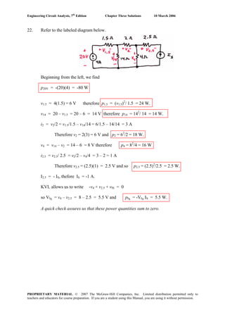
43. Define four mesh currents
By inspection, i1 = -4.5 A.
We form a supermesh with meshes 3 and 4 as defined above.
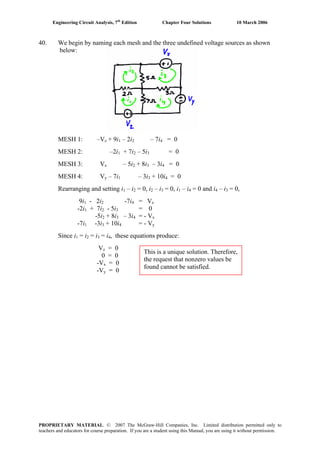
MESH 2: 2.2 + 3 i + 4 i2 2 + 5 – 4 i = 0 [1]3
SUPERMESH: 3 i4 + 9 i4 – 9 i1 + 4 i3 – 4 i2 + 6 i3 + i3 – 3 = 0 [2]
Supermesh KCL equation: i4 - i = 2 [3]3
Simplifying and combining terms, we may rewrite these three equations as:
7 i2 – 4 i3 = -7.2 [1]
-4 i2 + 11 i + 12 i = -37.5 [2]3 4
- i + i = 2 [3]3 4
Solving, we find that i2 = -2.839 A, i3 = -3.168 A, and i = -1.168 A.4
The power supplied by the 2.2-V source is then 2.2 (i – i ) = -3.654 W.1 2
i1 i2
i4i3
PROPRIETARY MATERIAL. © 2007 The McGraw-Hill Companies, Inc. Limited distribution permitted only to
teachers and educators for course preparation. If you are a student using this Manual, you are using it without permission.](https://image.slidesharecdn.com/xgizwmivsiwpds00swny-signature-f172ed6d5ea07afd7eea979324352a9b3640d1cd0448b6e1a174e81551e308e0-poli-140819203045-phpapp01/85/Engineering-circuit-analysis_solutions_7ed_-hayt-172-320.jpg)
![Engineering Circuit Analysis, 7th
Edition Chapter Four Solutions 10 March 2006
44. We begin by defining six mesh currents as depicted below:
i5 i6
i3i2i1 i4
We form a supermesh with meshes 1 and 2 since they share a current source.•
• We form a second supermesh with meshes 3 and 4 since they also share a current
source.
1, 2 Supermesh:
(4700 + 1000 + 10,000) i1 – 2200 i5 + (2200 + 1000 + 4700) i2 – 1000 i3 = 0 [1]
3, 4 Supermesh:
– 1000 i(4700 + 1000 + 2200) i3 2 – 2200 i6 + (4700 + 10,000 + 1000) i = 0 [2]4
MESH 5: (2200 + 4700) i – 2200 i5 2 + 3.2 – 1.5 = 0 [3]
MESH 6: 1.5 + (4700 + 4700 + 2200) c – 2200 i3 = 0 [4]
1, 2 Supermesh KCL equation: i1 – i2 = 3×10⁻³
[5]
3, 4 Supermesh KCL equation: i4 – i3 = 2×10⁻³
[6]
We can simplify these equations prior to solution in several ways. Choosing to retain
six equations,
15,700 i1 + 7900 i2 - 1000 i3 -2200 i5 = 0 [1]
- 1000 i2 + 7900 i3 + 15,700 i4 -2200 i = 0 [2]6
- 2200 i2 + 6900 i5 = -1.7 [3]
+ 11,600 i- 2200 i3 6 = -1.5 [4]
i1 – i2 = 3×10⁻³
[5]
- i3 + i = 2×10⁻³
[6]4
Solving, we find that i4 = 540.8 mA. Thus, the voltage across the 2-mA source is
(4700 + 10,000 + 1000) (540.8×10⁻⁶
) = 8.491 V
PROPRIETARY MATERIAL. © 2007 The McGraw-Hill Companies, Inc. Limited distribution permitted only to
teachers and educators for course preparation. If you are a student using this Manual, you are using it without permission.](https://image.slidesharecdn.com/xgizwmivsiwpds00swny-signature-f172ed6d5ea07afd7eea979324352a9b3640d1cd0448b6e1a174e81551e308e0-poli-140819203045-phpapp01/85/Engineering-circuit-analysis_solutions_7ed_-hayt-173-320.jpg)
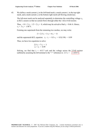
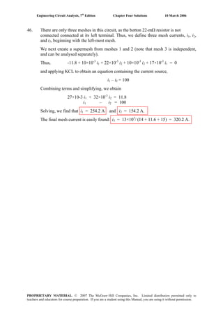
![Engineering Circuit Analysis, 7th
Edition Chapter Four Solutions 10 March 2006
47. MESH 1: -7 + i – i = 0 [1]1 2
MESH 2: i2 – i1 + 2i2 + 3i – 3i2 3 = 0 [2]
MESH 3: 3i3 – 3i2 + xi +2i – 7 = 0 [3]3 3
Grouping terms, we find that
i1 – i2 = 7 [1]
+ 6i – 3i-i = 0 [2]1 2 3
-3i + (5 + x)i2 3 = 7 [3]
This, unfortunately, is four unknowns but only three equations. However, we have not
yet made use of the fact that we are trying to obtain i2 = 2.273 A. Solving these “four”
equations, we find that
– 5 i )/ ix = (7 + 3 i2 3 3 = 4.498 Ω.
PROPRIETARY MATERIAL. © 2007 The McGraw-Hill Companies, Inc. Limited distribution permitted only to
teachers and educators for course preparation. If you are a student using this Manual, you are using it without permission.](https://image.slidesharecdn.com/xgizwmivsiwpds00swny-signature-f172ed6d5ea07afd7eea979324352a9b3640d1cd0448b6e1a174e81551e308e0-poli-140819203045-phpapp01/85/Engineering-circuit-analysis_solutions_7ed_-hayt-176-320.jpg)
![Engineering Circuit Analysis, 7th
Edition Chapter Four Solutions 10 March 2006
PROPRIETARY MATERIAL. © 2007 The McGraw-Hill Companies, Inc. Limited distribution permitted only to
teachers and educators for course preparation. If you are a student using this Manual, you are using it without permission.
7 V
7 A
1 Ω
2 Ω
3 Ω
300 mΩ
2 Ωi2 i3
i1
48. We begin by redrawing the circuit as instructed, and define three mesh currents:
By inspection, i3 = 7 A.
MESH 1: -7 + i – i = 0 or i1 2 1 – i2 = 7 [1]
MESH 2: (1 + 2 + 3) i – i –3(7) = 0 or -i + 6i = 21 [2]2 1 1 2
There is no need for supermesh techniques for this situation, as the only current
source lies on the outside perimeter of a mesh- it is not shared between meshes.
Solving, we find that i = 12.6 A, i = 5.6 A and i1 2 3 = 7 A.](https://image.slidesharecdn.com/xgizwmivsiwpds00swny-signature-f172ed6d5ea07afd7eea979324352a9b3640d1cd0448b6e1a174e81551e308e0-poli-140819203045-phpapp01/85/Engineering-circuit-analysis_solutions_7ed_-hayt-177-320.jpg)
![Engineering Circuit Analysis, 7th
Edition Chapter Four Solutions 10 March 2006
49. (a) We are asked for a voltage, and have one current source and one voltage source.
Nodal analysis is probably best then- the nodes can be named so that the desired
voltage is a nodal voltage, or, at worst, we have one supernode equation to solve.
Name the top left node “1” and the top right node “x”; designate the bottom node as
the reference terminal. Next, form a supernode with nodes “1” and “x.”
At the supernode: 11 = v1/ 2 + vx/ 9 [1]
and the KVL Eqn: v1 – v = 22 [2]x
Rearranging, 11(18) = 9 v1 + 2 v [1]x
22 = v1 – v [2]x
Solving, v = 0x
(b) We are asked for a voltage, and so may suspect that nodal analysis is preferrable;
with two current sources and only one voltage source (easily dealt with using the
supernode technique), nodal analysis does seem to have an edge over mesh analysis
here.
Name the top left node “x,” the top right node “y” and designate the bottom node as
the reference node. Forming a supernode from nodes “x” and “y,”
At the supernode: 6 + 9 = v / 10 + vx y/ 20 [1]
and the KVL Eqn: vy – v = 12 [2]x
Rearranging, 15(20) = 2 vx + v [1]y
and 12 = - vx + v [2]y
Solving, we find that vx = 96 V.
(c) We are asked for a voltage, but would have to subtract two nodal voltages (not
much harder than invoking Ohm’s law). On the other hand, the dependent current
source depends on the desired unknown, which would lead to the need for another
equation if invoking mesh analysis. Trying nodal analysis,
0.1 vx = (v1 – 50) / 2 + vx / 4 [1]
referring to the circuit we see that v = vx 1 – 100. Rearranging so that we may
eliminate v in Eq. [1], we obtain v = v1 1 x + 100. Thus, Eq. [1] becomes
0.1 vx = (vx + 100 – 50)/ 2 + vx / 4
and a little algebra yields vx = -38.46 V.
PROPRIETARY MATERIAL. © 2007 The McGraw-Hill Companies, Inc. Limited distribution permitted only to
teachers and educators for course preparation. If you are a student using this Manual, you are using it without permission.](https://image.slidesharecdn.com/xgizwmivsiwpds00swny-signature-f172ed6d5ea07afd7eea979324352a9b3640d1cd0448b6e1a174e81551e308e0-poli-140819203045-phpapp01/85/Engineering-circuit-analysis_solutions_7ed_-hayt-178-320.jpg)
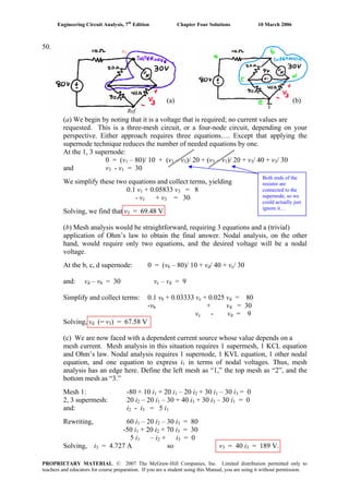
![Engineering Circuit Analysis, 7th
Edition Chapter Four Solutions 10 March 2006
51. This circuit consists of 3 meshes, and no dependent sources. Therefore 3 simultaneous
equations and 1 subtraction operation would be required to solve for the two desired
currents. On the other hand, if we use nodal analysis, forming a supernode about the
30-V source would lead to 5 – 1 – 1 = 3 simulataneous equations as well, plus several
subtraction and division operations to find the currents. Thus, mesh analysis has a
slight edge here.
Define three clockwise mesh currents: ia in the left-most mesh, ib in the top right
mesh, and i in the bottom right mesh. Then our mesh equations will be:c
Mesh a: -80 + (10 + 20 + 30) ia – 20 ib – 30 ic = 0 [1]
– 12 i – 20 iMesh b: -30 + (12 + 20) ib c a = 0 [2]
Mesh c: (12 + 40 + 30) ic – 12 i – 30 ib a = 0 [3]
Simplifying and collecting terms,
60 ia – 20 i – 30 ib c = 80 [1]
-20 ia + 32 ib – 12 ic = 30 [2]
-30 ia – 12 i + 82 ib c = 0 [3]
Solving, we find that ia = 3.549 A, i = 3.854 A, and ib c = 1.863 A. Thus,
i1 = ia = 3.549 A and i2 = ia – ic = 1.686 A.
PROPRIETARY MATERIAL. © 2007 The McGraw-Hill Companies, Inc. Limited distribution permitted only to
teachers and educators for course preparation. If you are a student using this Manual, you are using it without permission.](https://image.slidesharecdn.com/xgizwmivsiwpds00swny-signature-f172ed6d5ea07afd7eea979324352a9b3640d1cd0448b6e1a174e81551e308e0-poli-140819203045-phpapp01/85/Engineering-circuit-analysis_solutions_7ed_-hayt-180-320.jpg)
![Engineering Circuit Analysis, 7th
Edition Chapter Four Solutions 10 March 2006
52. Approaching this problem using nodal analysis would require 3 separate nodal
equations, plus one equation to deal with the dependent source, plus subtraction and
division steps to actually find the current i10. Mesh analysis, on the other hand, will
require 2 mesh/supermesh equations, 1 KCL equation, and one subtraction step to find
i10. Thus, mesh analysis has a clear edge. Define three clockwise mesh currents: i1 in
the bottom left mesh, i in the top mesh, and i in the bottom right mesh.2 3
MESH 1: i1 = 5 mA by inspection [1]
SUPERMESH: i1 – i2 = 0.4 i10
i1 – i2 = 0.4(i3 – i2)
i1 – 0.6 i2 – 0.4 i3 = 0 [2]
MESH 3: -5000 i – 10000 i1 2 + 35000 i3 = 0 [3]
Simplify: 0.6 i2 + 0.4 i = 5×10⁻³
[2]3
+ 35000 i-10000 i2 3 = 25 [3]
Solving, we find i2 = 6.6 mA and i = 2.6 mA. Since i3 10 = i3 – i2, we find that
i10 = -4 mA.
PROPRIETARY MATERIAL. © 2007 The McGraw-Hill Companies, Inc. Limited distribution permitted only to
teachers and educators for course preparation. If you are a student using this Manual, you are using it without permission.](https://image.slidesharecdn.com/xgizwmivsiwpds00swny-signature-f172ed6d5ea07afd7eea979324352a9b3640d1cd0448b6e1a174e81551e308e0-poli-140819203045-phpapp01/85/Engineering-circuit-analysis_solutions_7ed_-hayt-181-320.jpg)
![Engineering Circuit Analysis, 7th
Edition Chapter Four Solutions 10 March 2006
53. For this circuit problem, nodal analysis will require 3 simultaneous nodal equations,
then subtraction/ division steps to obtain the desired currents. Mesh analysis requires
1 mesh equation, 1 supermesh equation, 2 simple KCL equations and one subtraction
step to determine the currents. If either technique has an edge in this situation, it’s
probably mesh analysis. Thus, define four clockwise mesh equations: ia in the bottom
left mesh, i in the top left mesh, ib c in the top right mesh, and id in the bottom right
mesh.
At the a, b, c supermesh: -100 + 6 ia + 20 ib + 4 ic + 10 ic – 10 id = 0 [1]
Mesh d: 100 + 10 id – 10 ic + 24 id = 0 [2]
KCL: - ia + ib = 2 [3]
+ iand - ib c = 3 i3 = 3 ia [4]
Collecting terms & simplifying,
6 ia + 20 i + 14 ib c – 10 i = 100 [1]d
-10 ic + 34 i = -100 [2]d
- ia + ib = 2 [3]
-3 ia – i + ib c = 0 [4]
Solving,
ia = 0.1206 A, i = 2.121 A, ib c = 2.482 A, and id = -2.211 A. Thus,
i3 = ia = 120.6 mA and i10 = ic – i = 4.693 A.d
PROPRIETARY MATERIAL. © 2007 The McGraw-Hill Companies, Inc. Limited distribution permitted only to
teachers and educators for course preparation. If you are a student using this Manual, you are using it without permission.](https://image.slidesharecdn.com/xgizwmivsiwpds00swny-signature-f172ed6d5ea07afd7eea979324352a9b3640d1cd0448b6e1a174e81551e308e0-poli-140819203045-phpapp01/85/Engineering-circuit-analysis_solutions_7ed_-hayt-182-320.jpg)
![Engineering Circuit Analysis, 7th
Edition Chapter Four Solutions 10 March 2006
54. With 7 nodes in this circuit, nodal analysis will require the solution of three
simultaneous nodal equations (assuming we make use of the supernode technique)
and one KVL equation. Mesh analysis will require the solution of three simultaneous
mesh equations (one mesh current can be found by inspection), plus several
subtraction and multiplication operations to finally determine the voltage at the
central node. Either will probably require a comparable amount of algebraic
manoeuvres, so we go with nodal analysis, as the desired unknown is a direct result of
solving the simultaneous equations. Define the nodes as:
v1
v2
v3
v4
v5
v6
NODE 1: -2×10-3
= (v1 – 1.3)/ 1.8×10³
→ v = -2.84 V.1
2, 4 Supernode:
-3
2.3×10 = (v2 – v5)/ 1x10³
+ (v4 – 1.3)/ 7.3×10³
+ (v4 – v5)/ 1.3×10³ 3
+ v / 1.5×10⁴
KVL equation: -v + v2 4 = 5.2
Node 5: 0 = (v5 – v2)/ 1x10³
+ (v5 – v4)/ 1.3x10³
+ (v5 – 2.6)/ 6.3x10³
Simplifying and collecting terms,
14.235 v + 22.39 v – 25.185 v = 35.275 [1]2 4 5
-v2 + v = 5.2 [2]4
-8.19 v2 – 6.3 v + 15.79 v = 3.38 [3]4 5
Solving, we find the voltage at the central node is v4 = 3.460 V.
PROPRIETARY MATERIAL. © 2007 The McGraw-Hill Companies, Inc. Limited distribution permitted only to
teachers and educators for course preparation. If you are a student using this Manual, you are using it without permission.](https://image.slidesharecdn.com/xgizwmivsiwpds00swny-signature-f172ed6d5ea07afd7eea979324352a9b3640d1cd0448b6e1a174e81551e308e0-poli-140819203045-phpapp01/85/Engineering-circuit-analysis_solutions_7ed_-hayt-183-320.jpg)
![Engineering Circuit Analysis, 7th
Edition Chapter Four Solutions 10 March 2006
55. Mesh analysis yields current values directly, so use that approach. We therefore
in the left-most mesh, then i , idefine four clockwise mesh currents, starting with i1 2 3
and i moving towards the right.4
Mesh 1: -0.8i + (2 + 5) i – 5 i = 0 [1]x 1 2
Mesh 2: i2 = 1 A by inspection [2]
Mesh 3: (3 + 4) i3 – 3(1) – 4(i ) = 0 [3]4
Mesh 4: (4 + 3) i4 – 4 i3 – 5 = 0 [4]
Simplify and collect terms, noting that i = i – i = i – 1x 1 2 1
-0.8(i1 – 1) + 7 i – 5(1) = 0 yields i = 677.4 mA1 1
Thus, [3] and [4] become: 7 i3 – 4 i4 = 3 [3]
-4 i + 7 i = 5 [4]3 4
Solving, we find that i = 1.242 A and i3 4 = 1.424 A. A map of individual branch
currents can now be drawn:
↑
677.4 mA
677.4 mA
→
-322.6 mA
↓ -242.0 mA
↓
↑
182.0 mA
↑
-1.424 A
PROPRIETARY MATERIAL. © 2007 The McGraw-Hill Companies, Inc. Limited distribution permitted only to
teachers and educators for course preparation. If you are a student using this Manual, you are using it without permission.](https://image.slidesharecdn.com/xgizwmivsiwpds00swny-signature-f172ed6d5ea07afd7eea979324352a9b3640d1cd0448b6e1a174e81551e308e0-poli-140819203045-phpapp01/85/Engineering-circuit-analysis_solutions_7ed_-hayt-184-320.jpg)
![Engineering Circuit Analysis, 7th
Edition Chapter Four Solutions 10 March 2006
56. If we choose to perform mesh analysis, we require 2 simultaneous equations (there are
four meshes, but one mesh current is known, and we can employ the supermesh
technique around the left two meshes). In order to find the voltage across the 2-mA
source we will need to write a KVL equation, however. Using nodal analysis is less
desirable in this case, as there will be a large number of nodal equations needed.
Thus, we define four clockwise mesh currents i1, i , i and i2 3 4 starting with the left-
most mesh and moving towards the right of the circuit.
At the 1,2 supermesh: 2000 i1 + 6000 i2 – 3 + 5000 i2 = 0 [1]
and i1 – i2 = 2×10⁻³
[2]
by inspection, i4 = -1 mA. However, this as well as any equation for mesh
four are unnecessary: we already have two equations in two unknowns and i and i1 2
are sufficient to enable us to find the voltage across the current source.
Simplifying, we obtain 2000 i1 + 11000 i2 = 3 [1]
1000 i1 - 1000 i2 = 2 [2]
Solving, i = 1.923 mA and i = -76.92 μA.1 2
Thus, the voltage across the 2-mA source (“+” reference at the top of the source) is
v = -2000 i1 – 6000 (i1 – i2) = -15.85 V.
PROPRIETARY MATERIAL. © 2007 The McGraw-Hill Companies, Inc. Limited distribution permitted only to
teachers and educators for course preparation. If you are a student using this Manual, you are using it without permission.](https://image.slidesharecdn.com/xgizwmivsiwpds00swny-signature-f172ed6d5ea07afd7eea979324352a9b3640d1cd0448b6e1a174e81551e308e0-poli-140819203045-phpapp01/85/Engineering-circuit-analysis_solutions_7ed_-hayt-185-320.jpg)
![Engineering Circuit Analysis, 7th
Edition Chapter Four Solutions 10 March 2006
57. Nodal analysis will require 2 nodal equations (one being a “supernode” equation), 1
KVL equation, and subtraction/division operations to obtain the desired current. Mesh
analysis simply requires 2 “supermesh” equations and 2 KCL equations, with the
desired current being a mesh current. Thus, we define four clockwise mesh currents
ia, i , ib c, i starting with the left-most mesh and proceeding to the right of the circuit.d
At the a, b supermesh: -5 + 2 ia + 2 ib + 3 ib – 3 ic = 0 [1]
At the c, d supermesh: 3 ic – 3 i + 1 + 4 i = 0 [2]b d
and ia - i = 3 [3]b
ic - i = 2 [4]d
Simplifying and collecting terms, we obtain
2 ia + 5 i – 3 ib c = 5 [1]
-3 i + 3 ib c + 4 i = -1 [2]d
ia - i = 3 [3]b
ic - i = 2 [4]d
Solving, we find ia = 3.35 A, i = 350 mA, ib c = 1.15 A, and id = -850 mA. As i1 = ib,
i1 = 350 mA.
PROPRIETARY MATERIAL. © 2007 The McGraw-Hill Companies, Inc. Limited distribution permitted only to
teachers and educators for course preparation. If you are a student using this Manual, you are using it without permission.](https://image.slidesharecdn.com/xgizwmivsiwpds00swny-signature-f172ed6d5ea07afd7eea979324352a9b3640d1cd0448b6e1a174e81551e308e0-poli-140819203045-phpapp01/85/Engineering-circuit-analysis_solutions_7ed_-hayt-186-320.jpg)
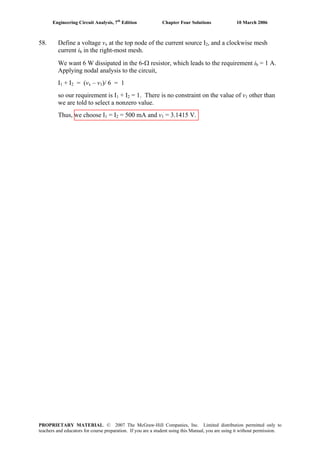
![Engineering Circuit Analysis, 7th
Edition Chapter Four Solutions 10 March 2006
59. Inserting the new 2-V source with “+” reference at the bottom, and the new 7-mA
source with the arrow pointing down, we define four clockwise mesh currents i1, i2, i3,
i4 starting with the left-most mesh and proceeding towards the right of the circuit.
Mesh 1: (2000 + 1000 + 5000) i – 6000 i1 2 – 2 = 0 [1]
2, 3 Supermesh:
– 6000 i2 + (5000 + 5000 + 1000 + 6000) i2 1 + (3000 + 4000 + 5000) i – 5000 i3 4
= 0 [2]
and i2 - i = 7×10⁻³
[3]3
Mesh 4: i4 = -1 mA by inspection [4]
Simplifying and combining terms,
8000 i1 – 6000 i2 = 2 [1]
1000 i2 – 1000 i3 = 7 [4]
-6000 i + 17000 i1 2 + 12000 i3 = -7 [2]
Solving, we find that
i1 = 2.653 A, i2 = 3.204 A, i = -3.796 A, i = -1 mA3 4
PROPRIETARY MATERIAL. © 2007 The McGraw-Hill Companies, Inc. Limited distribution permitted only to
teachers and educators for course preparation. If you are a student using this Manual, you are using it without permission.](https://image.slidesharecdn.com/xgizwmivsiwpds00swny-signature-f172ed6d5ea07afd7eea979324352a9b3640d1cd0448b6e1a174e81551e308e0-poli-140819203045-phpapp01/85/Engineering-circuit-analysis_solutions_7ed_-hayt-188-320.jpg)
![Engineering Circuit Analysis, 7th
Edition Chapter Four Solutions 10 March 2006
60. This circuit is easily analyzed by mesh analysis; it’s planar, and after combining the
2A and 3 A sources into a single 1 A source, supermesh analysis is simple.
, i , i and iFirst, define clockwise mesh currents ix 1 2 3 starting from the left-most mesh
and moving to the right. Next, combine the 2 A and 3 A sources temporarily into a 1
A source, arrow pointing upwards. Then, define four nodal voltages, V , V , V1 2 3 and
V moving from left to right along the top of the circuit.4
= –5 iAt the left-most mesh, i [1]x 1
– 2iFor the supermesh, we can write 4i1 x + 2 + 2i3 = 0 [2]
– iand the corresponding KCL equation: i = 1 [3]3 1
Substituting Eq. [1] into Eq. [2] and simplifying,
14i1 + 2i3 = –2
–i1 + i3 = 1
Solving, i = –250 mA and i1 3 = 750 mA.
Then, i = -5 ix 1 = 1.35 A and i = i – 2 = –2.25 A2 1
Nodal voltages are straightfoward to find, then:
V = 2i = 1.5 V4 3
V = 2 + V = 3.5 V3 4
V = 2 i = 2 i– V2 3 1 or V + V = 3 V2 1 3
V = 2 i = 2 i– V1 2 x or V + V = 5.5 V1 x 2
PROPRIETARY MATERIAL. © 2007 The McGraw-Hill Companies, Inc. Limited distribution permitted only to
teachers and educators for course preparation. If you are a student using this Manual, you are using it without permission.](https://image.slidesharecdn.com/xgizwmivsiwpds00swny-signature-f172ed6d5ea07afd7eea979324352a9b3640d1cd0448b6e1a174e81551e308e0-poli-140819203045-phpapp01/85/Engineering-circuit-analysis_solutions_7ed_-hayt-189-320.jpg)
![Engineering Circuit Analysis, 7th
Edition Chapter Four Solutions 10 March 2006
61. Hand analysis:
Define three clockwise mesh currents: i in the bottom left mesh, i1 2 in the top mesh,
and i in the bottom right mesh.3
MESH 1: i1 = 5 mA by inspection [1]
SUPERMESH: i1 – i2 = 0.4 i10
i1 – i2 = 0.4(i3 – i2)
i1 – 0.6 i2 – 0.4 i3 = 0 [2]
MESH 3: -5000 i – 10000 i1 2 + 35000 i3 = 0 [3]
Simplify: 0.6 i2 + 0.4 i = 5×10⁻³
[2]3
+ 35000 i-10000 i2 3 = 25 [3]
Solving, we find i2 = 6.6 mA and i = 2.6 mA. Since i3 10 = i3 – i2, we find that
i10 = -4 mA.
PSpice simulation results:
i10
→
Summary: The current entering the right-hand node of the 10-kΩ resistor R2 is
equal to 4.000 mA. Since this current is –i10, i10 = -4.000 mA as found by hand.
PROPRIETARY MATERIAL. © 2007 The McGraw-Hill Companies, Inc. Limited distribution permitted only to
teachers and educators for course preparation. If you are a student using this Manual, you are using it without permission.](https://image.slidesharecdn.com/xgizwmivsiwpds00swny-signature-f172ed6d5ea07afd7eea979324352a9b3640d1cd0448b6e1a174e81551e308e0-poli-140819203045-phpapp01/85/Engineering-circuit-analysis_solutions_7ed_-hayt-190-320.jpg)
![Engineering Circuit Analysis, 7th
Edition Chapter Four Solutions 10 March 2006
62. Hand analysis:
Define the nodes as:
v1
v2
v3
v4
v5
v6
NODE 1: -2×10-3
= (v1 – 1.3)/ 1.8×10³
→ v = -2.84 V.1
2, 4 Supernode:
-3
2.3×10 = (v2 – v5)/ 1x10³
+ (v4 – 1.3)/ 7.3×10³
+ (v4 – v5)/ 1.3×10³ 3
+ v / 1.5×10⁴
KVL equation: -v + v2 4 = 5.2
Node 5: 0 = (v5 – v2)/ 1x10³
+ (v5 – v4)/ 1.3x10³
+ (v5 – 2.6)/ 6.3x10³
Simplifying and collecting terms,
14.235 v + 22.39 v – 25.185 v = 35.275 [1]2 4 5
-v2 + v = 5.2 [2]4
-8.19 v2 – 6.3 v + 15.79 v = 3.38 [3]4 5
Solving, we find the voltage at the central node is v4 = 3.460 V.
PSpice simulation results:
Summary: The voltage at the center node is found to be 3.460 V, which is in
agreement with our hand calculation.
PROPRIETARY MATERIAL. © 2007 The McGraw-Hill Companies, Inc. Limited distribution permitted only to
teachers and educators for course preparation. If you are a student using this Manual, you are using it without permission.](https://image.slidesharecdn.com/xgizwmivsiwpds00swny-signature-f172ed6d5ea07afd7eea979324352a9b3640d1cd0448b6e1a174e81551e308e0-poli-140819203045-phpapp01/85/Engineering-circuit-analysis_solutions_7ed_-hayt-191-320.jpg)
![Engineering Circuit Analysis, 7th
Edition Chapter Four Solutions 10 March 2006
63. Hand analysis:
At the 1,2 supermesh: 2000 i1 + 6000 i2 – 3 + 5000 i2 = 0 [1]
and i1 – i2 = 2×10⁻³
[2]
by inspection, i4 = -1 mA. However, this as well as any equation for mesh
four are unnecessary: we already have two equations in two unknowns and i and i1 2
are sufficient to enable us to find the voltage across the current source.
Simplifying, we obtain 2000 i1 + 11000 i2 = 3 [1]
1000 i1 - 1000 i2 = 2 [2]
Solving, i = 1.923 mA and i = -76.92 μA.1 2
Thus, the voltage across the 2-mA source (“+” reference at the top of the source) is
v = -2000 i1 – 6000 (i1 – i2) = -15.85 V.
PSpice simulation results:
Summary: Again arbitrarily selecting the “+” reference as the top node of the
2-mA current source, we find the voltage across it is –5.846 – 10 = -15.846 V, in
agreement with our hand calculation.
PROPRIETARY MATERIAL. © 2007 The McGraw-Hill Companies, Inc. Limited distribution permitted only to
teachers and educators for course preparation. If you are a student using this Manual, you are using it without permission.](https://image.slidesharecdn.com/xgizwmivsiwpds00swny-signature-f172ed6d5ea07afd7eea979324352a9b3640d1cd0448b6e1a174e81551e308e0-poli-140819203045-phpapp01/85/Engineering-circuit-analysis_solutions_7ed_-hayt-192-320.jpg)
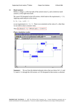
![Engineering Circuit Analysis, 7th
Edition Chapter Four Solutions 10 March 2006
65. Hand analysis:
Define node 1 as the top left node, and node 2 as the node joining the three 2-Ω
resistors. Place the “+” reference terminal of the 2-V source at the right. The right-
most 2-Ω resistor has therefore been shorted out. Applying nodal analysis then,
= (v – vNode 1: -5 i1 1 2)/ 2 [1]
– vNode 2: 0 = (v2 1)/ 2 + v2/ 2 + (v – 2)/ 2 [2]2
and, i1 = (v – 2)/ 2 [3]2
Simplifying and collecting terms,
v1 + v = 10 [1]2
+ 3 v-v1 2 = 2 [2]
Solving, we find that v1 = 3.143 V and v2 = 1.714 V.
Defining clockwise mesh currents ia, i , ib c, id starting with the left-most mesh and
proceeding right, we may easily determine that
ia = -5 i1 = 714.3 mA
ib = -142.9 mA
ic = i – 2 = -2.143 A1
id = 3 + ic = 857.1 mA
PSpice simulation results:
Summary: The simulation results agree with the hand calculations.
PROPRIETARY MATERIAL. © 2007 The McGraw-Hill Companies, Inc. Limited distribution permitted only to
teachers and educators for course preparation. If you are a student using this Manual, you are using it without permission.](https://image.slidesharecdn.com/xgizwmivsiwpds00swny-signature-f172ed6d5ea07afd7eea979324352a9b3640d1cd0448b6e1a174e81551e308e0-poli-140819203045-phpapp01/85/Engineering-circuit-analysis_solutions_7ed_-hayt-194-320.jpg)
![Engineering Circuit Analysis, 7th
Edition Chapter Four Solutions 10 March 2006
66. (a) One possible circuit configuration of many that would satisfy the requirements:
↑5 V 3 A 2 vx
100 Ω
50 Ω
20 Ω
10 Ω
+ vx -
At node 1: -3 = (v1 – 5)/ 100 + (v – v2)/ 50 [1]1
At node 2: 2 vx = (v2 – v1)/ 50 + v / 30 [2]2
and, vx = 5 – v [3]1
Simplifying and collecting terms,
150 v1 – 100 v2 = -14750 [1]
2970 v1 + 80 v2 = 15000 [2]
Solving, we find that v1 = 1.036 V and v2 = 149.1 V.
The current through the 100-Ω resistor is simply (5 – v )/100 = 39.64 mA1
– vThe current through the 50-Ω resistor is (v1 2)/ 50 = -2.961 A,
and the current through the 20-Ω and 10-Ω series combination is v2/ 30 = 4.97 A.
Finally, the dependent source generates a current of 2 v = 7.928 A.x
(b) PSpice simulation results
Summary: The simulated results agree with the hand calculations.
PROPRIETARY MATERIAL. © 2007 The McGraw-Hill Companies, Inc. Limited distribution permitted only to
teachers and educators for course preparation. If you are a student using this Manual, you are using it without permission.](https://image.slidesharecdn.com/xgizwmivsiwpds00swny-signature-f172ed6d5ea07afd7eea979324352a9b3640d1cd0448b6e1a174e81551e308e0-poli-140819203045-phpapp01/85/Engineering-circuit-analysis_solutions_7ed_-hayt-195-320.jpg)
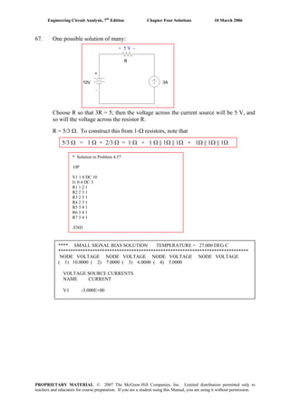
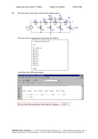
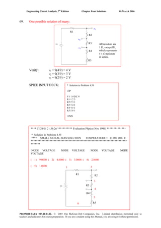
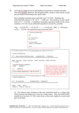
![Engineering Circuit Analysis, 7th
Edition Chapter Five Solutions 10 March 2006
1. Define percent error as 100 [ex
– (1 + x)]/ ex
x 1 + x ex
% error
0.001 1.001 1.001 5×10⁻⁵
0.005 1.005 1.005 1×10⁻³
0.01 1.01 1.010 5×10⁻³
0.05 1.05 1.051 0.1
0.10 1.10 1.105 0.5
0.50 1.50 1.649 9
1.00 2.00 2.718 26
5.00 6.00 148.4 96
Of course, “reasonable” is a very subjective term. However, if we choose x < 0.1, we
ensure that the error is less than 1%.
PROPRIETARY MATERIAL. © 2007 The McGraw-Hill Companies, Inc. Limited distribution permitted only to
teachers and educators for course preparation. If you are a student using this Manual, you are using it without permission.](https://image.slidesharecdn.com/xgizwmivsiwpds00swny-signature-f172ed6d5ea07afd7eea979324352a9b3640d1cd0448b6e1a174e81551e308e0-poli-140819203045-phpapp01/85/Engineering-circuit-analysis_solutions_7ed_-hayt-200-320.jpg)
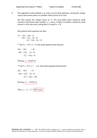
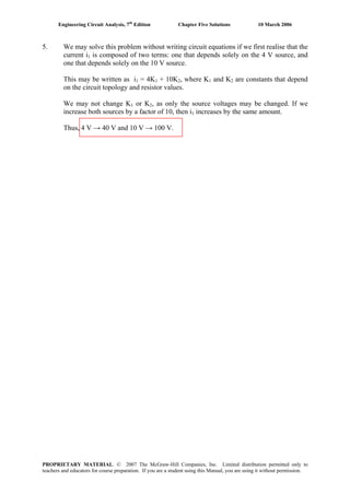
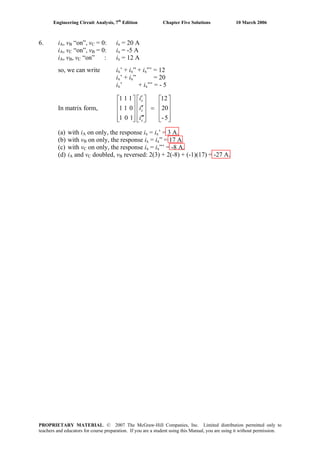
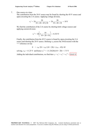
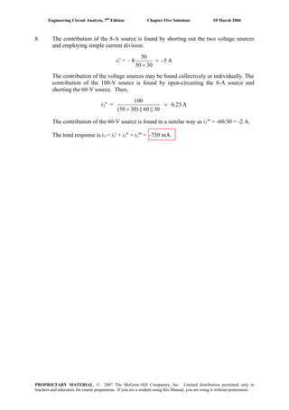
![Engineering Circuit Analysis, 7th
Edition Chapter Five Solutions 10 March 2006
9. (a) By current division, the contribution of the 1-A source i2’ is
i2’ = 1 (200)/ 250 = 800 mA.
The contribution of the 100-V source is i2” = 100/ 250 = 400 mA.
The contribution of the 0.5-A source is found by current division once the 1-A source
is open-circuited and the voltage source is shorted. Thus,
i2”’ = 0.5 (50)/ 250 = 100 mA
Thus, i2 = i2’ + i2” + i2”’ = 1.3 A
(b) P1A = (1) [(200)(1 – 1.3)] = 60 W
P200 = (1 – 1.3)2
(200) = 18 W
P100V = -(1.3)(100) = -130 W
P50 = (1.3 – 0.5)2
(50) = 32 W
P0.5A = (0.5) [(50)(1.3 – 0.5)] = 20 W
Check: 60 + 18 + 32 + 20 = +130.
PROPRIETARY MATERIAL. © 2007 The McGraw-Hill Companies, Inc. Limited distribution permitted only to
teachers and educators for course preparation. If you are a student using this Manual, you are using it without permission.](https://image.slidesharecdn.com/xgizwmivsiwpds00swny-signature-f172ed6d5ea07afd7eea979324352a9b3640d1cd0448b6e1a174e81551e308e0-poli-140819203045-phpapp01/85/Engineering-circuit-analysis_solutions_7ed_-hayt-208-320.jpg)
![Engineering Circuit Analysis, 7th
Edition Chapter Five Solutions 10 March 2006
10. We find the contribution of the 4-A source by shorting out the 100-V source and
analysing the resulting circuit:
4 = V1' / 20 + (V1' – V')/ 10 [1]
0.4 i1' = V1'/ 30 + (V' – V1')/ 10 [2]
where i1' = V1'/ 20
Simplifying & collecting terms, we obtain 30 V1' – 20 V' = 800 [1]
-7.2 V1' + 8 V' = 0 [2]
Solving, we find that V' = 60 V. Proceeding to the contribution of the 60-V source, we
analyse the following circuit after defining a clockwise mesh current ia flowing in the
left mesh and a clockwise mesh current ib flowing in the right mesh.
30 ia – 60 + 30 ia – 30 ib = 0 [1]
ib = -0.4 i1" = +0.4 ia [2]
Solving, we find that ia = 1.25 A and so V" = 30(ia – ib) = 22.5 V.
Thus, V = V' + V" = 82.5 V.
'
'
"
"
'
"
PROPRIETARY MATERIAL. © 2007 The McGraw-Hill Companies, Inc. Limited distribution permitted only to
teachers and educators for course preparation. If you are a student using this Manual, you are using it without permission.](https://image.slidesharecdn.com/xgizwmivsiwpds00swny-signature-f172ed6d5ea07afd7eea979324352a9b3640d1cd0448b6e1a174e81551e308e0-poli-140819203045-phpapp01/85/Engineering-circuit-analysis_solutions_7ed_-hayt-209-320.jpg)
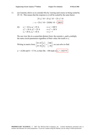
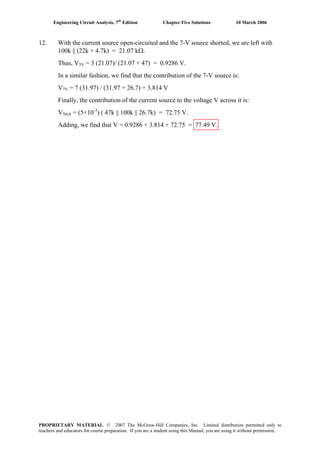
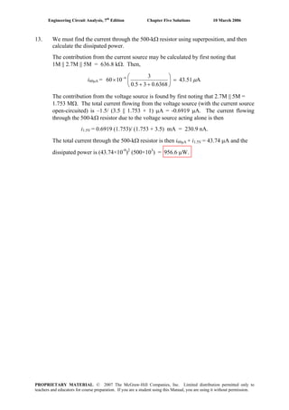
![Engineering Circuit Analysis, 7th
Edition Chapter Five Solutions 10 March 2006
14. We first determine the contribution of the voltage source:
'
↑
I1'
'
Via mesh analysis, we write: 5 = 18000 I1' – 17000 Ix'
-6 Ix' = -17000 Ix' + 39000 Ix'
Solving, we find I1' = 472.1 mA and Ix' = 205.8 mA, so V' = 17×103
(I1' - Ix')
= 4.527 V. We proceed to find the contribution of the current source:
Vx"V"
Via supernode: -20×10-3
= Vx"/ 22×103
+ V"/ 0.9444×10³
[1]
and V" – Vx" = 6Ix" or V" – Vx" = 6 Vx"/ 22×103
[2]
Solving, we find that V" = -18.11 V. Thus, V = V' + V" = -13.58 V.
The maximum power is V2
/ 17×103
= V2
/ 17 mW = 250 mW, so
V = ( )(17)(250) 65.19 V - -18.11′= = . Solving, we find = 83.3 V.maxV′
The 5-V source may then be increased by a factor of 83.3/ 4.527, so that its
maximum positive value is 92 V; past this value, and the resistor will overheat.
PROPRIETARY MATERIAL. © 2007 The McGraw-Hill Companies, Inc. Limited distribution permitted only to
teachers and educators for course preparation. If you are a student using this Manual, you are using it without permission.](https://image.slidesharecdn.com/xgizwmivsiwpds00swny-signature-f172ed6d5ea07afd7eea979324352a9b3640d1cd0448b6e1a174e81551e308e0-poli-140819203045-phpapp01/85/Engineering-circuit-analysis_solutions_7ed_-hayt-213-320.jpg)
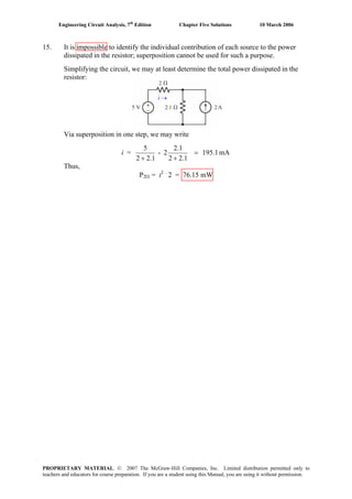
![Engineering Circuit Analysis, 7th
Edition Chapter Five Solutions 10 March 2006
16. We will analyse this circuit by first considering the combined effect of both dc
sources (left), and then finding the effect of the single ac source acting alone (right).
IB
IB
V1
V2
V3
vx'
1, 3 supernode: V1/ 100 + V1/ 17×103
+ (V1 – 15)/ 33×103
+ V3/ 103
= 20 IB [1]
and: V1 – V3 = 0.7 [2]
Node 2: -20 IB = (V2 – 15)/ 1000 [3]
We require one additional equation if we wish to have IB as an unknown:
20 IB + IB = V3/ 1000 [4]
Simplifying and collecting terms,
10.08912 V1 + V3 – 20×103
IB = 0.4545 [1]
V1 - V3 = 0.7 [2]
V2 + 20×103
IB = 15 [3]
-V3 + 21×103 IB = 0 [4]
Solving, we find that IB = -31.04 μA.
To analyse the right-hand circuit, we first find the Thévenin equivalent to the left of
the wire marked iB', noting that the 33-kΩ and 17-kΩ resistors are now in parallel. We
find that VTH = 16.85 cos 6t V by voltage division, and RTH = 100 || 17k || 33k =
99.12 Ω. We may now proceed:
20 iB' = vB
x' / 1000 + (vx' – 16.85 cos 6t)/ 99.12 [1]
20 iB' + iB
B'' = vx'/ 1000 [2]
Solving, we find that iB' = 798.6 cos 6t mA. Thus, adding our two results, we find the
complete current is
iB = iB
B' + IB = -31.04 + 798.6 cos 6t μA.
PROPRIETARY MATERIAL. © 2007 The McGraw-Hill Companies, Inc. Limited distribution permitted only to
teachers and educators for course preparation. If you are a student using this Manual, you are using it without permission.](https://image.slidesharecdn.com/xgizwmivsiwpds00swny-signature-f172ed6d5ea07afd7eea979324352a9b3640d1cd0448b6e1a174e81551e308e0-poli-140819203045-phpapp01/85/Engineering-circuit-analysis_solutions_7ed_-hayt-215-320.jpg)
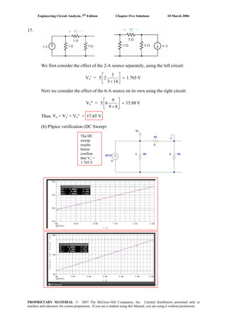
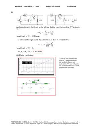
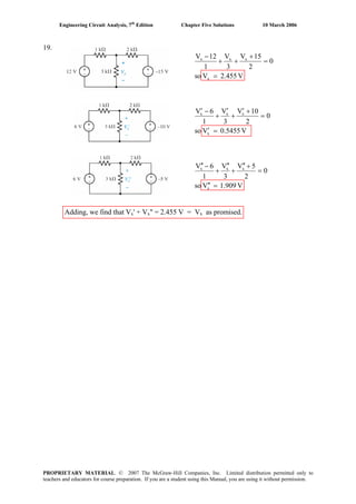
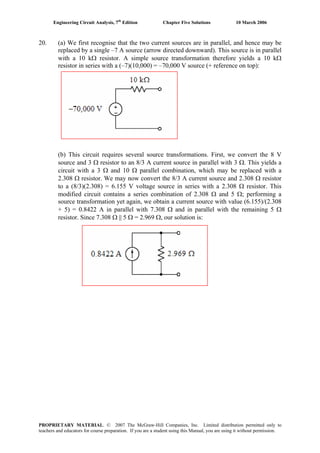
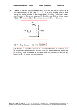
![Engineering Circuit Analysis, 7th
Edition Chapter Five Solutions 10 March 2006
22. (a) [120 cos 400t] / 60 = 2 cos 400t A. 60 || 120 = 40 Ω.
[2 cos 400t] (40) = 80 cos 400t V. 40 + 10 = 50 Ω.
[80 cos 400t]/ 50 = 1.6 cos 400t A. 50 || 50 = 25 Ω.
25 Ω1.6 cos 400t A
(b) 2k || 3k + 6k = 7.2 kΩ. 7.2k || 12k = 4.5 kΩ
(20)(4.5) = 90 V.
4.5 kΩ
3.5 kΩ
8 kΩ
PROPRIETARY MATERIAL. © 2007 The McGraw-Hill Companies, Inc. Limited distribution permitted only to
teachers and educators for course preparation. If you are a student using this Manual, you are using it without permission.](https://image.slidesharecdn.com/xgizwmivsiwpds00swny-signature-f172ed6d5ea07afd7eea979324352a9b3640d1cd0448b6e1a174e81551e308e0-poli-140819203045-phpapp01/85/Engineering-circuit-analysis_solutions_7ed_-hayt-221-320.jpg)
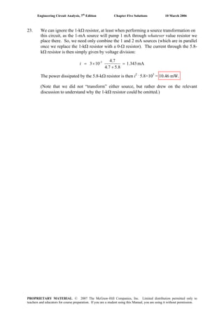
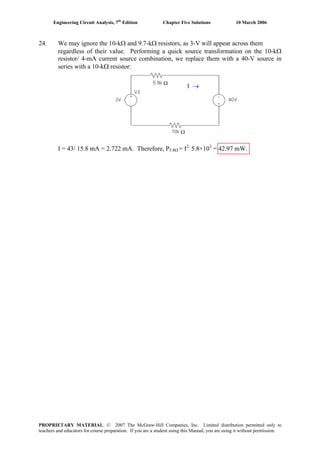
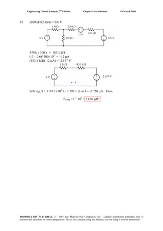
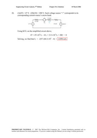
![Engineering Circuit Analysis, 7th
Edition Chapter Five Solutions 10 March 2006
27. (a) (2 V1)(17) = 34 V1
34
← I
Analysing the simplified circuit above,
34 V1 – 0.6 + 7 I + 2 I + 17 I = 0 [1] and V1 = 2 I [2]
Substituting, we find that I = 0.6/ (68 + 7 + 2 + 17) = 6.383 mA. Thus,
V1 = 2 I = 12.77 mV
(b)
V1 is the top-labelled voltage (12.77 mV).
PROPRIETARY MATERIAL. © 2007 The McGraw-Hill Companies, Inc. Limited distribution permitted only to
teachers and educators for course preparation. If you are a student using this Manual, you are using it without permission.](https://image.slidesharecdn.com/xgizwmivsiwpds00swny-signature-f172ed6d5ea07afd7eea979324352a9b3640d1cd0448b6e1a174e81551e308e0-poli-140819203045-phpapp01/85/Engineering-circuit-analysis_solutions_7ed_-hayt-226-320.jpg)
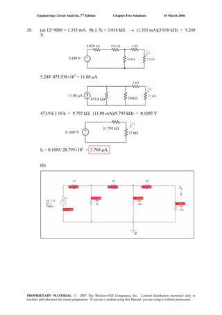
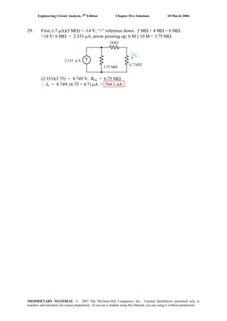
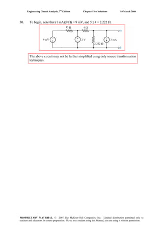
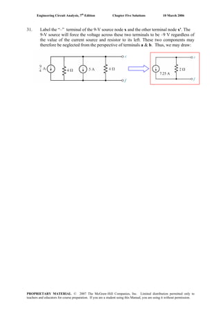
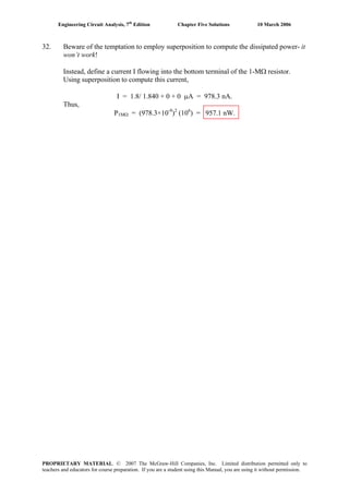
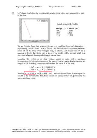
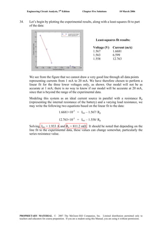
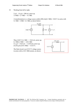
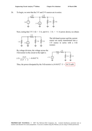
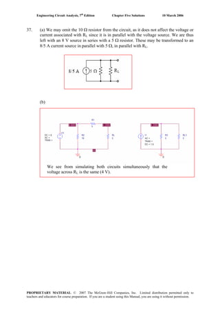
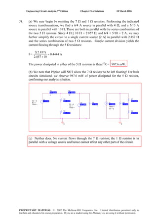
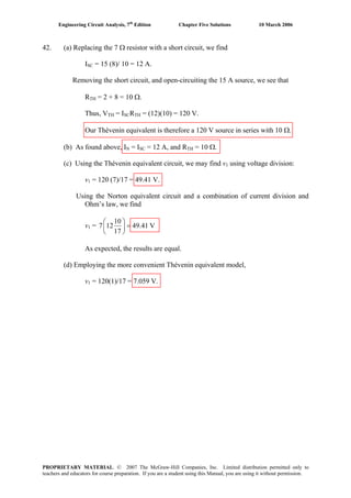
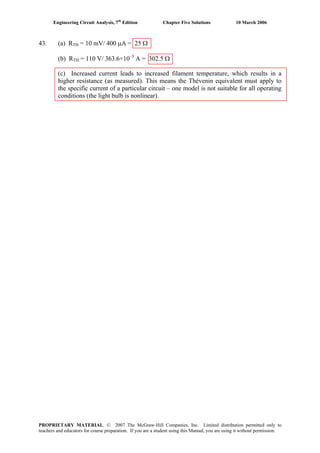
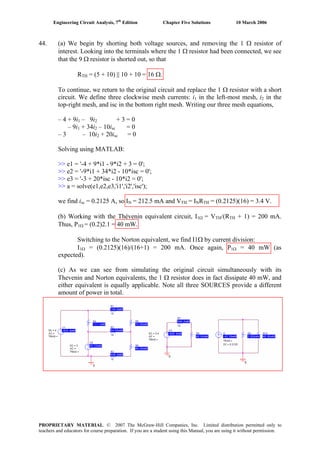
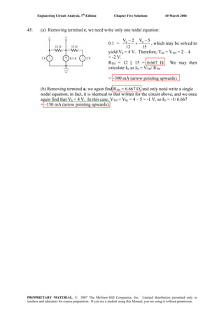
![Engineering Circuit Analysis, 7th
Edition Chapter Five Solutions 10 March 2006
46. (a) Shorting out the 88-V source and open-circuiting the 1-A source, we see looking
into the terminals x and x' a 50-Ω resistor in parallel with 10 Ω in parallel with
(20 Ω + 40 Ω), so
RTH = 50 || 10 || (20 + 40) = 7.317 Ω
Using superposition to determine the voltage Vxx' across the 50-Ω resistor, we find
Vxx' = VTH = ⎥
⎦
⎤
⎢
⎣
⎡
++
+⎥
⎦
⎤
⎢
⎣
⎡
++
+
)10||50(2040
40
10)||(1)(50
)]4020(||50[10
)4020(||50
88
= ⎥
⎦
⎤
⎢
⎣
⎡
++
+⎥
⎦
⎤
⎢
⎣
⎡
333.82040
40
(1)(8.333)
27.37
27.27
88 = 69.27 V
(b) Shorting out the 88-V source and open-circuiting the 1-A source, we see looking
into the terminals y and y' a 40-Ω resistor in parallel with [20 Ω + (10 Ω || 50 Ω)]:
RTH = 40 || [20 + (10 || 50)] = 16.59 Ω
Using superposition to determine the voltage Vyy' across the 1-A source, we find
Vyy' = VTH = (1)(RTH) + ⎟
⎠
⎞
⎜
⎝
⎛
+⎥
⎦
⎤
⎢
⎣
⎡
+ 4020
40
27.2710
27.27
88
= 59.52 V
PROPRIETARY MATERIAL. © 2007 The McGraw-Hill Companies, Inc. Limited distribution permitted only to
teachers and educators for course preparation. If you are a student using this Manual, you are using it without permission.](https://image.slidesharecdn.com/xgizwmivsiwpds00swny-signature-f172ed6d5ea07afd7eea979324352a9b3640d1cd0448b6e1a174e81551e308e0-poli-140819203045-phpapp01/85/Engineering-circuit-analysis_solutions_7ed_-hayt-245-320.jpg)
![Engineering Circuit Analysis, 7th
Edition Chapter Five Solutions 10 March 2006
47. (a) Select terminal b as the reference terminal, and define a nodal voltage V1 at the
top of the 200-Ω resistor. Then,
0 =
200
V
100
VV
40
20V 1TH11
+
−
+
−
[1]
1.5 i1 = (VTH – V1)/ 100 [2]
where i1 = V1/ 200, so Eq. [2] becomes 150 V1/ 200 + V1 - VTH = 0 [2]
Simplifying and collecting terms, these equations may be re-written as:
(0.25 + 0.1 + 0.05) V1 – 0.1 VTH = 5 [1]
(1 + 15/ 20) V1 – VTH = 0 [2]
Solving, we find that VTH = 38.89 V. To find RTH, we short the voltage source and
inject 1 A into the port:
0 =
200
V
40
V
100
VV 11in1
++
−
[1]
1.5 i1 + 1 =
100
VV 1in −
[2]
i1 = V1/ 200 [3]
1 A
+
Vin
-
V1
Ref.
Combining Eqs. [2] and [3] yields 1.75 V1 – Vin = -100 [4]
Solving Eqs. [1] & [4] then results in Vin = 177.8 V, so that RTH = Vin/ 1 A = 177.8 Ω.
(b) Adding a 100-Ω load to the original circuit or our Thévenin equivalent, the
voltage across the load is
V100Ω = V14.00
177.8100
100
VTH =⎟
⎠
⎞
⎜
⎝
⎛
+
, and so P100Ω = (V100Ω)2
/ 100 = 1.96 W.
PROPRIETARY MATERIAL. © 2007 The McGraw-Hill Companies, Inc. Limited distribution permitted only to
teachers and educators for course preparation. If you are a student using this Manual, you are using it without permission.](https://image.slidesharecdn.com/xgizwmivsiwpds00swny-signature-f172ed6d5ea07afd7eea979324352a9b3640d1cd0448b6e1a174e81551e308e0-poli-140819203045-phpapp01/85/Engineering-circuit-analysis_solutions_7ed_-hayt-246-320.jpg)
![Engineering Circuit Analysis, 7th
Edition Chapter Five Solutions 10 March 2006
48. We inject a current of 1 A into the port (arrow pointing up), select the bottom terminal
as our reference terminal, and define the nodal voltage Vx across the 200-Ω resistor.
Then, 1 = V1/ 100 + (V1 – Vx)/ 50 [1]
-0.1 V1 = Vx/ 200 + (Vx – V1)/ 50 [2]
which may be simplified to
3 V1 – 2 Vx = 100 [1]
16 V1 + 5 Vx = 0 [2]
Solving, we find that V1 = 10.64 V, so RTH = V1/ (1 A) = 10.64 Ω.
Since there are no independent sources present in the original network, IN = 0.
PROPRIETARY MATERIAL. © 2007 The McGraw-Hill Companies, Inc. Limited distribution permitted only to
teachers and educators for course preparation. If you are a student using this Manual, you are using it without permission.](https://image.slidesharecdn.com/xgizwmivsiwpds00swny-signature-f172ed6d5ea07afd7eea979324352a9b3640d1cd0448b6e1a174e81551e308e0-poli-140819203045-phpapp01/85/Engineering-circuit-analysis_solutions_7ed_-hayt-247-320.jpg)
![Engineering Circuit Analysis, 7th
Edition Chapter Five Solutions 10 March 2006
49. With no independent sources present, VTH = 0.
We decide to inject a 1-A current into the port:
Ref.
vx
vf
•
A
Node ‘x’: 0.01 vab = vx/ 200 + (vx – vf)/ 50 [1]
Supernode: 1 = vab/ 100 + (vf – vx) [2]
and: vab – vf = 0.2 vab [3]
Rearranging and collecting terms,
-2 vab + 5 vx – 4 vf = 0 [1]
vab – 2 vx + 2 vf = 100 [2]
0.8 vab - vf = 0 [3]
Solving, we find that vab = 192.3 V, so RTH = vab/ (1 A) = 192.3 Ω.
PROPRIETARY MATERIAL. © 2007 The McGraw-Hill Companies, Inc. Limited distribution permitted only to
teachers and educators for course preparation. If you are a student using this Manual, you are using it without permission.](https://image.slidesharecdn.com/xgizwmivsiwpds00swny-signature-f172ed6d5ea07afd7eea979324352a9b3640d1cd0448b6e1a174e81551e308e0-poli-140819203045-phpapp01/85/Engineering-circuit-analysis_solutions_7ed_-hayt-248-320.jpg)
![Engineering Circuit Analysis, 7th
Edition Chapter Five Solutions 10 March 2006
50. We first find RTH by shorting out the voltage source and open-circuiting the current
source.
Looking into the terminals a & b, we see
RTH = 10 || [47 + (100 || 12)]
= 8.523 Ω.
Returning to the original circuit, we decide to perform nodal analysis to obtain VTH:
-12×103
= (V1 – 12)/ 100×103
+ V1/ 12×103
+ (V1 – VTH)/ 47×103
[1]
12×103
= VTH/ 10×103
+ (VTH – V1)/ 47×103
[2]
Rearranging and collecting terms,
0.1146 V1 - 0.02128 VTH = -11.88 [1]
-0.02128 V1 + 0.02128 VTH = 12 [2]
Solving, we find that VTH = 83.48 V.
PROPRIETARY MATERIAL. © 2007 The McGraw-Hill Companies, Inc. Limited distribution permitted only to
teachers and educators for course preparation. If you are a student using this Manual, you are using it without permission.](https://image.slidesharecdn.com/xgizwmivsiwpds00swny-signature-f172ed6d5ea07afd7eea979324352a9b3640d1cd0448b6e1a174e81551e308e0-poli-140819203045-phpapp01/85/Engineering-circuit-analysis_solutions_7ed_-hayt-249-320.jpg)
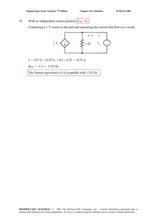
![Engineering Circuit Analysis, 7th
Edition Chapter Five Solutions 10 March 2006
54. Performing nodal analysis to determine VTH,
100×10-3
= Vx/ 250 + Voc/ 7.5×10³
[1]
and Vx – Voc = 5 ix
where ix = Vx/ 250. Thus, we may write the second equation as
0.98 Vx – Voc = 0 [2]
Solving, we find that Voc = VTH = 23.72 V.
In order to determine RTH, we inject 1 A into the port:
Vab/ 7.5×10³
+ Vx/ 250 = 1 [1]
and Vx – Vab = 5 ix = 5Vx/ 250 or
-Vab + (1 – 5/ 250) Vx = 0 [2]
Solving, we find that Vab = 237.2 V. Since RTH = Vab/ (1 A), RTH = 237.2 Ω.
Finally, IN = VTH/ RTH = 100 mA.
PROPRIETARY MATERIAL. © 2007 The McGraw-Hill Companies, Inc. Limited distribution permitted only to
teachers and educators for course preparation. If you are a student using this Manual, you are using it without permission.](https://image.slidesharecdn.com/xgizwmivsiwpds00swny-signature-f172ed6d5ea07afd7eea979324352a9b3640d1cd0448b6e1a174e81551e308e0-poli-140819203045-phpapp01/85/Engineering-circuit-analysis_solutions_7ed_-hayt-253-320.jpg)
![Engineering Circuit Analysis, 7th
Edition Chapter Five Solutions 10 March 2006
56. Shorting out the voltage source, we redraw the circuit with a 1-A source in place of
the 2-kΩ resistor:
Noting that 300 Ω || 2 MΩ ≈ 300 Ω,
0 = (vgs – V)/ 300 [1]
1 – 0.02 vgs = V/ 1000 + (V – vgs)/ 300 [2]
Simplifying & collecting terms,
vgs – V = 0 [1]
0.01667 vgs + 0.00433 V = 1 [2]
Solving, we find that vgs = V = 47.62 V. Hence, RTH = V/ 1 A = 47.62 Ω.
1 A
Ref.
V
PROPRIETARY MATERIAL. © 2007 The McGraw-Hill Companies, Inc. Limited distribution permitted only to
teachers and educators for course preparation. If you are a student using this Manual, you are using it without permission.](https://image.slidesharecdn.com/xgizwmivsiwpds00swny-signature-f172ed6d5ea07afd7eea979324352a9b3640d1cd0448b6e1a174e81551e308e0-poli-140819203045-phpapp01/85/Engineering-circuit-analysis_solutions_7ed_-hayt-255-320.jpg)
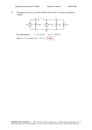
![Engineering Circuit Analysis, 7th
Edition Chapter Five Solutions 10 March 2006
58. Removing the voltage source and the 300-Ω resistor, we replace them with a 1-A
source and seek the voltage that develops across its terminals:
1 A
+
V
-
Ref.
We select the bottom node as our reference terminal, and define nodal voltages V1
and V2. Then,
1 = V1 / 2×10⁶
+ (V1 – V2)/ rπ [1]
0.02 vπ = (V2 – V1)/ rπ + V2/ 1000 + V2/ 2000 [2]
where vπ = V1 – V2
Simplifying & collecting terms,
(2×10⁶
+ rπ) V1 – 2×10⁶
V2 = 2×10⁶
rπ [1]
-(2000 + 40 rπ) V1 + (2000 + 43 rπ) V2 = 0 [2]
Solving, we find that V1 = V = ⎟⎟
⎠
⎞
⎜⎜
⎝
⎛
++×
+
×
π
π
r14.33666.7102
r14.33666.7
102 6
6
.
Thus, RTH = 2×10⁶
|| (666.7 + 14.33 rπ) Ω.
PROPRIETARY MATERIAL. © 2007 The McGraw-Hill Companies, Inc. Limited distribution permitted only to
teachers and educators for course preparation. If you are a student using this Manual, you are using it without permission.](https://image.slidesharecdn.com/xgizwmivsiwpds00swny-signature-f172ed6d5ea07afd7eea979324352a9b3640d1cd0448b6e1a174e81551e308e0-poli-140819203045-phpapp01/85/Engineering-circuit-analysis_solutions_7ed_-hayt-257-320.jpg)
![Engineering Circuit Analysis, 7th
Edition Chapter Five Solutions 10 March 2006
59. (a) We first determine vout in terms of vin and the resistor values only; in this case,
VTH = vout. Performing nodal analysis, we write two equations:
( ) ( )
1
0 d in d od
i f
v v v vv
R R R
− − − −−
= + + [1] and
( ) ( )0 o d o d
f o
v v v Av
R R
+ −
= + [2]
Solving using MATLAB, we obtain:
>> e1 = 'vd/Ri + (vd + vin)/R1 + (vd + vo)/Rf = 0';
>> e2 = '(vo + vd)/Rf + (vo – A*vd)/Ro = 0';
>> a = solve(e1,e2,'vo','vd');
>> pretty(a.vo)
Ri vin (–Ro + Rf A)
– -----------------------------------------------
R1 Ro + Ri Ro + R1 Rf + Ri Rf + R1 Ri + A R1 Ri
Thus, VTH =
1 1 1 1
( )in i o f
o i o f i f i i
v R R AR
R R R R R R R R R R AR R
−
+ + + + +
, which in the limit of A → ∞,
approaches –Rf/R1.
To find RTH, we short out the independent source vin, and squirt 1 A into the terminal
marked vout, renamed VT. Analyzing the resulting circuit, we write two nodal
equations:
( )
1
0 d Td d
i f
v vv v
R R R
− −−
= − + [1] and
( ) ( )1 [2]T d T d
f o
v v v Av
R R
+ −
= +
Solving using MATLAB:
>> e1 = 'vd/R1 + vd/Ri + (vd + VT)/Rf = 0';
>> e2 = '1 = (VT + vd)/Rf + (VT - A*vd)/Ro';
>> a = solve(e1,e2,'vd','VT');
>> pretty(a.VT)
Ro (Ri Rf + R1 Rf + R1 Ri)
--------------------------------------------------------------
Ri Ro + R1 Ro + Ri Rf + R1 Rf + R1 Ri + A R1 Ri
Since VT/1 = VT, this is our Thévenin equivalent resistance (RTH).
+
vout
–
PROPRIETARY MATERIAL. © 2007 The McGraw-Hill Companies, Inc. Limited distribution permitted only to
teachers and educators for course preparation. If you are a student using this Manual, you are using it without permission.](https://image.slidesharecdn.com/xgizwmivsiwpds00swny-signature-f172ed6d5ea07afd7eea979324352a9b3640d1cd0448b6e1a174e81551e308e0-poli-140819203045-phpapp01/85/Engineering-circuit-analysis_solutions_7ed_-hayt-258-320.jpg)
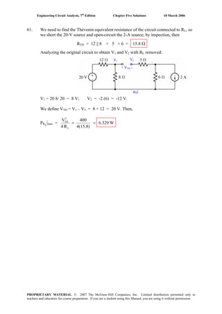
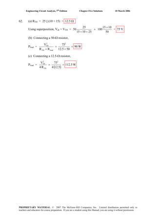
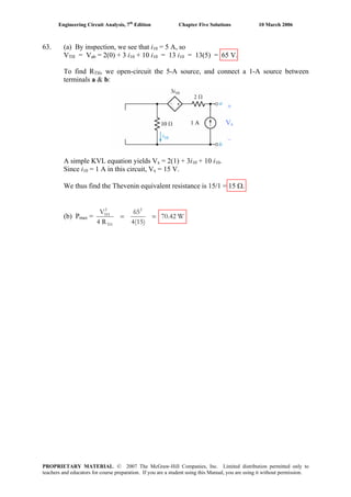
![Engineering Circuit Analysis, 7th
Edition Chapter Five Solutions 10 March 2006
64.
(a) Replacing the resistor RL with a 1-A source, we seek the voltage that develops across
its terminals with the independent voltage source shorted:
1 1 1
1 1
1
1
10 20 40 0 [1] 30 20 0 [1]
and 1 [2] 1 [2]
Solving, 400mA
So 40 16V and 16
1A
− + + = ⇒ + =
− = ⇒ − =
=
= = = = Ω
x x
x x
TH
i i i i i
i i i i
i
V
V i R
(b) Removing the resistor RL from the original circuit, we seek the resulting open-circuit
voltage:
+
VTH
-
1
1
10 50
0 [1]
20 40
50
where
40
1 50 5
so [1] becomes 0
20 2 40 40
50
0
20 80
0 4 50
5 50
or 10V
− −
= +
−
=
− −⎛ ⎞ ⎛ ⎞
= − +⎜ ⎟ ⎜ ⎟
⎝ ⎠ ⎝ ⎠
−
= +
= + −
=
=
TH TH
TH
TH TH TH
TH TH
TH TH
TH
TH
V i V
V
i
V V V
V V
V V
V
V
0
Thus, if 16 ,
5V
2
= = Ω
= =
+L
L TH
L TH
R TH
L TH
R R
R V
V V
R R
=
PROPRIETARY MATERIAL. © 2007 The McGraw-Hill Companies, Inc. Limited distribution permitted only to
teachers and educators for course preparation. If you are a student using this Manual, you are using it without permission.](https://image.slidesharecdn.com/xgizwmivsiwpds00swny-signature-f172ed6d5ea07afd7eea979324352a9b3640d1cd0448b6e1a174e81551e308e0-poli-140819203045-phpapp01/85/Engineering-circuit-analysis_solutions_7ed_-hayt-263-320.jpg)
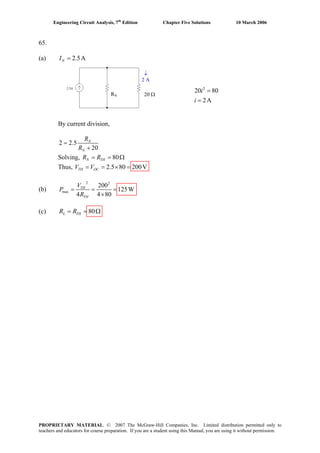
![Engineering Circuit Analysis, 7th
Edition Chapter Five Solutions 10 March 2006
66.
By Voltage ÷, =
+
N
R N
N
R
I I
R R
So
Solving, and1.7A=NI 33.33= ΩNR
(a) If
(b) If
(c) If
is a maximum,
33.33
33.33
1.7 850mA
33.33 33.33
33.33 28.33V
= = Ω
= × =
+
= =
L L
L N
L
L L
v i
R R
i
v i
ii s a maximum
; max when 0
So 1.7A
0V
= = Ω
+
=
=
L
N
L N L
N L
L
L
R
i i R
R R
i
v
0.2 = [1]
250
0.5 [2]
80
+
=
+
N
N
N
N
N
N
R
I
R
R
I
R
10W to 250 corresp to 200mA.
20W to 80 corresp to 500mA.RN R
IN
Ω
Ω
is av maximum
( )
So is a maximum when is a maximum, which occurs at .
Then 0 and 1.7 56.66V
=
= ∞
= = × =
L
L N N L
L N L L
L L N
V I R R
v R R R
i v R
PROPRIETARY MATERIAL. © 2007 The McGraw-Hill Companies, Inc. Limited distribution permitted only to
teachers and educators for course preparation. If you are a student using this Manual, you are using it without permission.](https://image.slidesharecdn.com/xgizwmivsiwpds00swny-signature-f172ed6d5ea07afd7eea979324352a9b3640d1cd0448b6e1a174e81551e308e0-poli-140819203045-phpapp01/85/Engineering-circuit-analysis_solutions_7ed_-hayt-265-320.jpg)
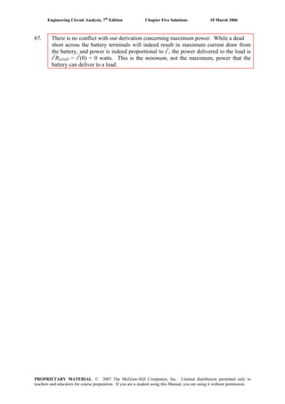
![Engineering Circuit Analysis, 7th
Edition Chapter Five Solutions 10 March 2006
68. Remove RE: =TH E inR R R
bottom node: 3
3
1 3 10 [1]
300 70 10
− π π
π
− −
− × = +
×
V v V v
v
at other node: 3 3
0
10 10 300 70 10
π π π− −
= + +
× ×
v v V v V
1 A
V
[2]
Simplifying and collecting terms,
210×105
= 70×103
V + 300V + 63000 vπ – 70x103
vπ - 300 vπ
3 5
3 3
3 3
or 70.3 10 7300 210 10 [1]
0 2100 70 10 70 10 300 300
or 69.7 10 72.4 10 0 [2]
solving, 331.9 So 331.9
π
π π π
π
× − = ×
= + × − × + −
− × + × =
= = ΩTH E
V v
v v V v
V v
V V R R
V
2i
2
0
Next, we determine vTH using mesh analysis:
3 3
1 270.3 10 70 10 0 [1]− + × − × =sv i i
3 3
2 1 380 10 70 10 0 [2]× − × + =Ei i R i
and: 3
3 2 3 10 [3]−
π− = ×i i v
or i i 3 3
3 2 3 10 (10 10 )−
− = × ×
or 3 2 30− =i i i
or
2 331 0 [3]− + =i i
Solving :
3 3
1
3 3
2
3
70.3 10 70 10 0
70 10 80 10 0
0 31 1
⎡ ⎤× − × ⎡ ⎤ ⎡ ⎤
⎢ ⎥ ⎢ ⎥ ⎢ ⎥− × × =⎢ ⎥ ⎢ ⎥ ⎢ ⎥
⎢ ⎥ ⎢ ⎥ ⎢ ⎥− ⎣ ⎦ ⎣ ⎦⎣ ⎦
s
E
i v
R i
i
We seek i3:
3
3 6 3
21.7 10
7.24 10 21.79 10
− ×
=
× + ×
s
E
v
i
R
So
3
3 6 3
21.7 10
7.24 10 21.79 10
− ×
= = =
× + ×
E
OC TH E s
E
R
V V R i v
R
2 23 2
8 26 3
6 2
2
6 3 2
21.7 10 8
8
8 7.24 10 21.79 10 331.9
331.9
11.35 10 (331.9 )
(7.24 10 21.79 10 )
Ω
⎡ ⎤ ⎡ ⎤− ×
= =⎢ ⎥ ⎢ ⎥
+ × + × ⎡ ⎤⎣ ⎦ ⎣ ⎦
⎢ ⎥+⎣ ⎦
× +
=
× + ×
TH E
TH E E
E
E
E
V R
P
R R R
R
R
vs
R
vs
This is maximized by setting .= ∞ER
PROPRIETARY MATERIAL. © 2007 The McGraw-Hill Companies, Inc. Limited distribution permitted only to
teachers and educators for course preparation. If you are a student using this Manual, you are using it without permission.](https://image.slidesharecdn.com/xgizwmivsiwpds00swny-signature-f172ed6d5ea07afd7eea979324352a9b3640d1cd0448b6e1a174e81551e308e0-poli-140819203045-phpapp01/85/Engineering-circuit-analysis_solutions_7ed_-hayt-267-320.jpg)
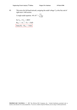
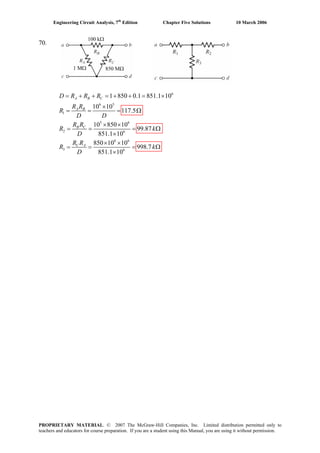
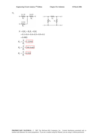
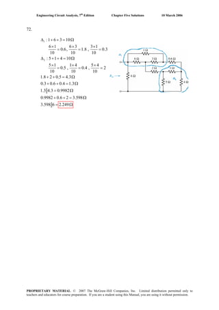
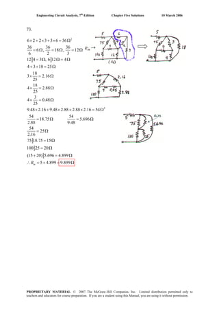
![Engineering Circuit Analysis, 7th
Edition Chapter Five Solutions 10 March 2006
74. We begin by converting the Δ-connected network consisting of the 4-, 6-, and 3-Ω
resistors to an equivalent Y-connected network:
RA
RB
RC
1
2
3
6 4 3 13
6 4
1.846
13
4 3
923.1m
13
3 6
1.385
13
= + + = Ω
×
= = = Ω
×
= = =
×
= = = Ω
A B
B C
C A
D
R R
R
D
R R
R
D
R R
R
D
Ω
Then network becomes:
1.846 Ω 0.9231 Ω
1.385 Ω
Then we may write
12 [13.846 (19.385 6.9231)]
7.347
= +
= Ω
inR
PROPRIETARY MATERIAL. © 2007 The McGraw-Hill Companies, Inc. Limited distribution permitted only to
teachers and educators for course preparation. If you are a student using this Manual, you are using it without permission.](https://image.slidesharecdn.com/xgizwmivsiwpds00swny-signature-f172ed6d5ea07afd7eea979324352a9b3640d1cd0448b6e1a174e81551e308e0-poli-140819203045-phpapp01/85/Engineering-circuit-analysis_solutions_7ed_-hayt-273-320.jpg)

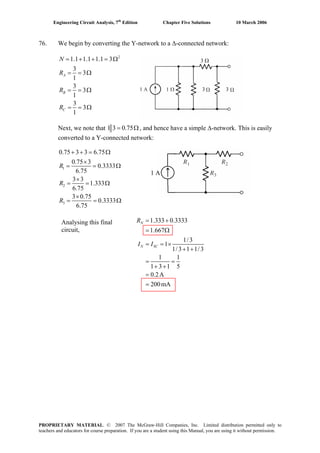
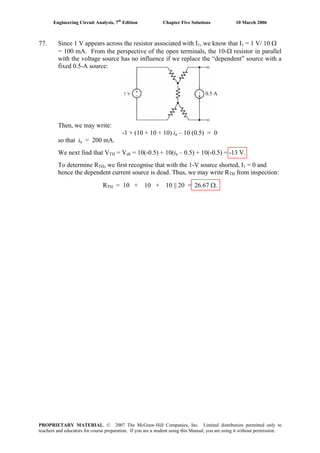
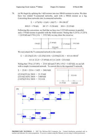
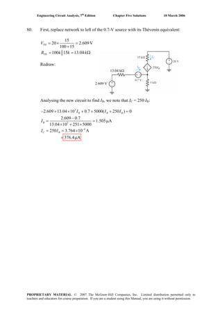
![Engineering Circuit Analysis, 7th
Edition Chapter Five Solutions 10 March 2006
81. (a) Define a nodal voltage V1 at the top of the current source IS, and a nodal voltage
V2 at the top of the load resistor RL. Since the load resistor can safely dissipate 1 W,
and we know that
PRL
=
1000
V2
2
then V31.62V max2 = . This corresponds to a load resistor (and hence lamp) current
of 32.62 mA, so we may treat the lamp as a 10.6-Ω resistor.
Proceeding with nodal analysis, we may write:
IS = V1/ 200 + (V1 – 5 Vx)/ 200 [1]
0 = V2/ 1000 + (V2 – 5 Vx)/ 10.6 [2]
Vx = V1 – 5 Vx or Vx = V1/ 6 [3]
Substituting Eq. [3] into Eqs. [1] and [2], we find that
7 V1 = 1200 IS [1]
-5000 V1 + 6063.6 V2 = 0 [2]
Substituting V31.62V max2 = into Eq. [2] then yields V1 = 38.35 V, so that
IS| max
= (7)(38.35)/ 1200 = 223.7 mA.
(b) PSpice verification.
The lamp current does not exceed 36 mA in the range of operation allowed
(i.e. a load power of < 1 W.) The simulation result shows that the load will dissipate
slightly more than 1 W for a source current magnitude of 224 mA, as predicted by
hand analysis.
PROPRIETARY MATERIAL. © 2007 The McGraw-Hill Companies, Inc. Limited distribution permitted only to
teachers and educators for course preparation. If you are a student using this Manual, you are using it without permission.](https://image.slidesharecdn.com/xgizwmivsiwpds00swny-signature-f172ed6d5ea07afd7eea979324352a9b3640d1cd0448b6e1a174e81551e308e0-poli-140819203045-phpapp01/85/Engineering-circuit-analysis_solutions_7ed_-hayt-280-320.jpg)
![Engineering Circuit Analysis, 7th
Edition Chapter Five Solutions 10 March 2006
82. Short out all but the source operating at 104
rad/s, and define three clockwise mesh
currents i1, i2, and i3 starting with the left-most mesh. Then
608 i1 – 300 i2 = 3.5 cos 104
t [1]
-300 i1 + 316 i2 – 8 i3 = 0 [2]
-8 i2 + 322 i3 = 0 [3]
Solving, we find that i1(t) = 10.84 cos 104
t mA
i2(t) = 10.29 cos 104
t mA
i3(t) = 255.7 cos 104
t μA
Next, short out all but the 7 sin 200t V source, and and define three clockwise mesh
currents ia, ib, and ic starting with the left-most mesh. Then
608 ia – 300 ib = -7 sin 200t [1]
-300 ia + 316 ib – 8 ic = 7 sin 200t [2]
-8 ib + 322 ic = 0 [3]
Solving, we find that ia(t) = -1.084 sin 200t mA
ib(t) = 21.14 sin 200t mA
ic(t) = 525.1 sin 200t μA
Next, short out all but the source operating at 103
rad/s, and define three clockwise
mesh currents iA, iB, and iC starting with the left-most mesh. Then
608 iA – 300 iB = 0 [1]B
-300 iA + 316 iB – 8 iB
C = 0 [2]
-8 iB + 322 iC = -8 cos 104
t [3]
Solving, we find that iA(t) = -584.5 cos 103
t μA
iB(t) = -1.185 cos 10 t mAB
3
iC(t) = -24.87 cos 103
t mA
We may now compute the power delivered to each of the three 8-Ω speakers:
p1 = 8[i1 + ia + iA]2
= 8[10.84×10⁻³
cos 104
t -1.084×10⁻³
sin 200t -584.5×10⁻⁶
cos 103
t]2
p2 = 8[i2 + ib + iB]2
= 8[10.29×10⁻³
cos 104
t +21.14×10⁻³
sin 200t –1.185×10⁻³
cos 103
t]2
p3 = 8[i3 + ic + iC]2
= 8[255.7×10⁻⁶
cos 104
t +525.1×10⁻⁶
sin 200t –24.87×10⁻³
cos 103
t]2
PROPRIETARY MATERIAL. © 2007 The McGraw-Hill Companies, Inc. Limited distribution permitted only to
teachers and educators for course preparation. If you are a student using this Manual, you are using it without permission.](https://image.slidesharecdn.com/xgizwmivsiwpds00swny-signature-f172ed6d5ea07afd7eea979324352a9b3640d1cd0448b6e1a174e81551e308e0-poli-140819203045-phpapp01/85/Engineering-circuit-analysis_solutions_7ed_-hayt-281-320.jpg)
![Engineering Circuit Analysis, 7th
Edition Chapter Five Solutions 10 March 2006
83. Replacing the DMM with a possible Norton equivalent (a 1-MΩ resistor in parallel
with a 1-A source):
1 A
Vin
We begin by noting that 33 Ω || 1 MΩ ≈ 33 Ω. Then,
0 = (V1 – Vin)/ 33 + V1/ 275×103
[1]
and
1 - 0.7 V1 = Vin/ 106
+ Vin/ 33×103
+ (Vin – V1)/ 33 [2]
Simplifying and collecting terms,
(275×103
+ 33) V1 - 275×103
Vin = 0 [1]
22.1 V1 + 1.001 Vin = 33 [2]
Solving, we find that Vin = 1.429 V; in other words, the DMM sees 1.429 V across its
terminals in response to the known current of 1 A it’s supplying. It therefore thinks
that it is connected to a resistance of 1.429 Ω.
PROPRIETARY MATERIAL. © 2007 The McGraw-Hill Companies, Inc. Limited distribution permitted only to
teachers and educators for course preparation. If you are a student using this Manual, you are using it without permission.](https://image.slidesharecdn.com/xgizwmivsiwpds00swny-signature-f172ed6d5ea07afd7eea979324352a9b3640d1cd0448b6e1a174e81551e308e0-poli-140819203045-phpapp01/85/Engineering-circuit-analysis_solutions_7ed_-hayt-282-320.jpg)
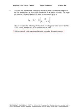
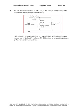
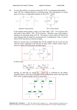
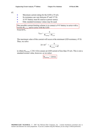
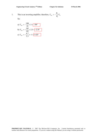
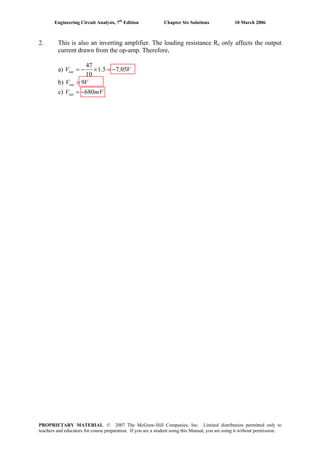
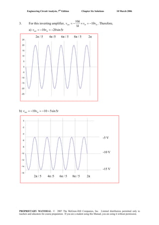
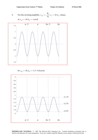
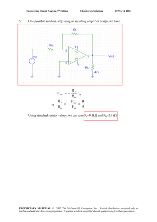
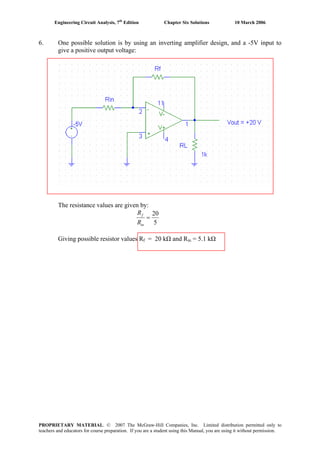
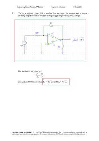
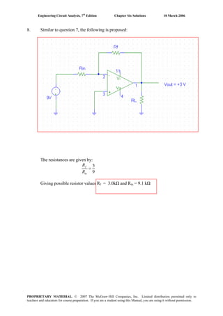
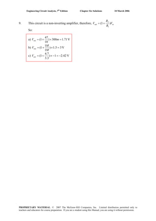
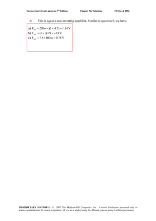
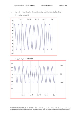
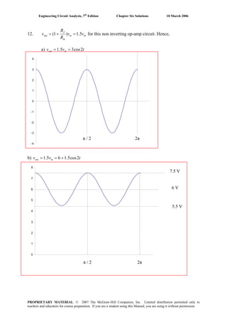
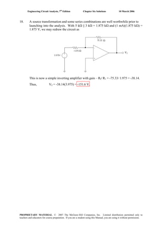
![Engineering Circuit Analysis, 7th
Edition Chapter Six Solutions 10 March 2006
22. Define a nodal voltage V- at the inverting input, and a nodal voltage V+ at the non-
inverting input. Then,
At the non-inverting input: -3×10-6
= 6
101.5
V
×
+
[1]
Thus, V+ = -4.5 V, and we therefore also know that V- = -4.5 V.
At the inverting input:
7
out-
6
-
R
V-V
R
V
0 += [2]
Solving and making use of the fact that V- = -4.5 V,
vout = ( ) V1
R
R
4.5-4.5-5.4
R
R
6
7
6
7
⎟⎟
⎠
⎞
⎜⎜
⎝
⎛
+=−
PROPRIETARY MATERIAL. © 2007 The McGraw-Hill Companies, Inc. Limited distribution permitted only to
teachers and educators for course preparation. If you are a student using this Manual, you are using it without permission.](https://image.slidesharecdn.com/xgizwmivsiwpds00swny-signature-f172ed6d5ea07afd7eea979324352a9b3640d1cd0448b6e1a174e81551e308e0-poli-140819203045-phpapp01/85/Engineering-circuit-analysis_solutions_7ed_-hayt-308-320.jpg)
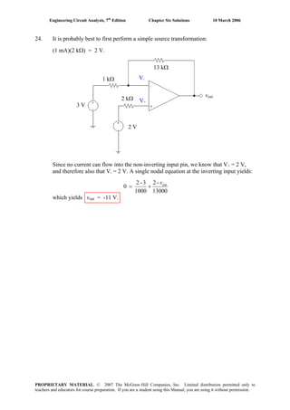
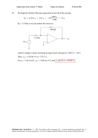
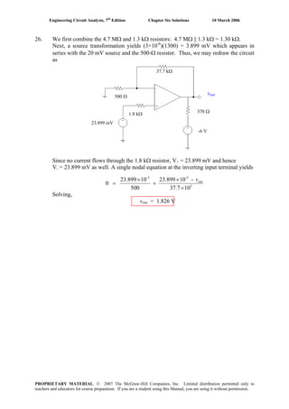
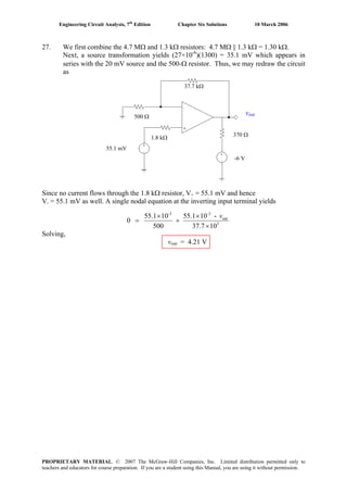
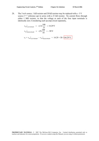
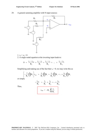
![Engineering Circuit Analysis, 7th
Edition Chapter Six Solutions 10 March 2006
30. A general difference amplifier:
Writing a nodal equation at the inverting input,
v1
v2
R1
R2
R3
R4
vout
f
a
1
1a
R
-
R
-
0 outvvvv
+=
Writing a nodal equation at the non-inverting input,
2
2b
3
b
R
-
R
0
vvv
+=
Simplifying and collecting terms, we may write
(Rf + R1) va – R1 vout = Rf v1 [1]
(R2 + R3) vb = R3 v2 [2]
From Eqn. [2], we have vb = 2
32
3
RR
R
v
+
Since va = vb, we can now rewrite Eqn. [1] as
( )
2
32
31f
1f1
RR
RRR
RR vvvout
+
+
−=−
and hence
2
32
1f
1
3
1
1
f
RR
RR
R
R
R
R
- vvvout ⎟⎟
⎠
⎞
⎜⎜
⎝
⎛
+
+
+=
PROPRIETARY MATERIAL. © 2007 The McGraw-Hill Companies, Inc. Limited distribution permitted only to
teachers and educators for course preparation. If you are a student using this Manual, you are using it without permission.](https://image.slidesharecdn.com/xgizwmivsiwpds00swny-signature-f172ed6d5ea07afd7eea979324352a9b3640d1cd0448b6e1a174e81551e308e0-poli-140819203045-phpapp01/85/Engineering-circuit-analysis_solutions_7ed_-hayt-316-320.jpg)
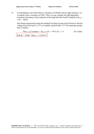
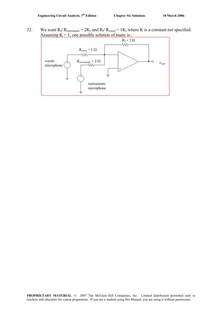
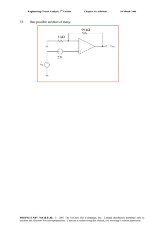
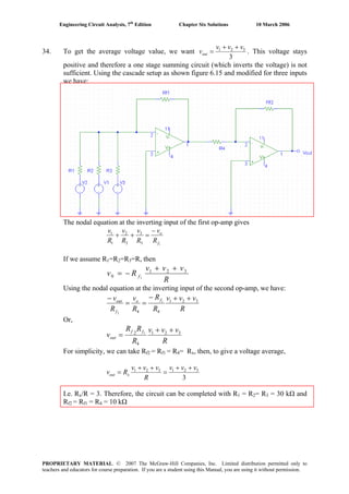
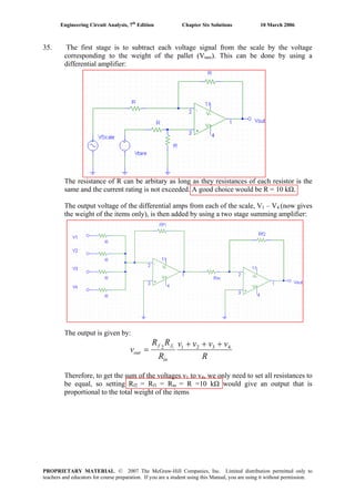
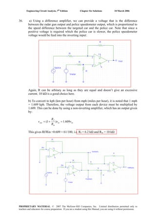
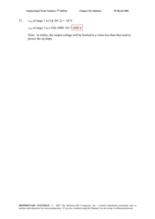
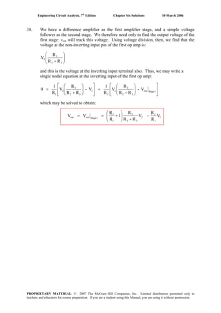
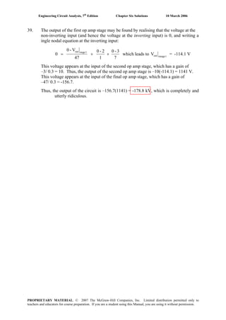
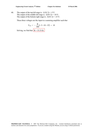
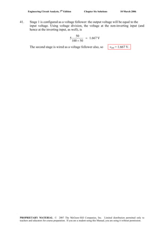
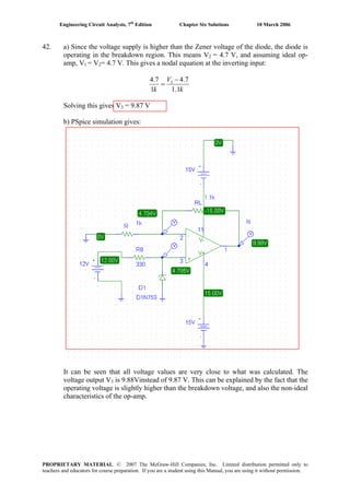
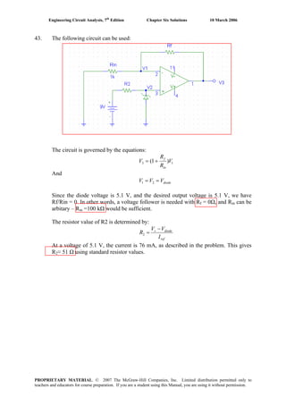
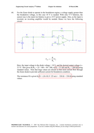
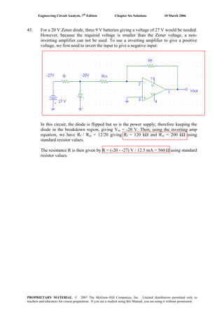
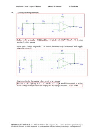
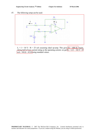
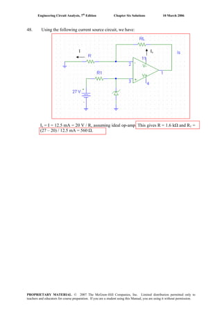
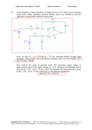
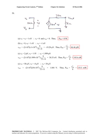
![Engineering Circuit Analysis, 7th
Edition Chapter Six Solutions 10 March 2006
51.
Writing a nodal equation at the “-vd” node,
f
outd
1
Sd
in
d
R
--
R
V--
R
-
0
vvvv
++= [1]
or (R1Rf + RinRf + RinR1) vd + RinR1vout = -RinRfVS [1]
Writing a nodal equation at the “vout” node,
f
dout
o
dout
R
)(--
R
A--
0
vvvv
+= [2]
Eqn. [2] can be rewritten as:
( )
out
fo
of
d
AR-R
RR-
vv
+
= [2]
so that Eqn. [1] becomes:
vout =
( )
ino1o1infin1f1in
Sofin
RRRRRRRRRRRAR
VR-ARR
-
+++++
where for this circuit, A = 106
, Rin = 10 TΩ, Ro = 15 Ω, Rf = 1000 kΩ, R1 = 270 kΩ.
(a) –3.704 mV; (b) 27.78 mV; (c) –3.704 V.
PROPRIETARY MATERIAL. © 2007 The McGraw-Hill Companies, Inc. Limited distribution permitted only to
teachers and educators for course preparation. If you are a student using this Manual, you are using it without permission.](https://image.slidesharecdn.com/xgizwmivsiwpds00swny-signature-f172ed6d5ea07afd7eea979324352a9b3640d1cd0448b6e1a174e81551e308e0-poli-140819203045-phpapp01/85/Engineering-circuit-analysis_solutions_7ed_-hayt-337-320.jpg)
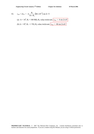
![Engineering Circuit Analysis, 7th
Edition Chapter Six Solutions 10 March 2006
53.
(a) Find vout/ vin if Ri = ∞, Ro = 0, and A is finite.
The nodal equation at the inverting input is
100
--
1
--
0 outdind vvvv
+= [1]
At the output, with Ro = 0 we may write vout = Avd so vd = vout/ A. Thus, Eqn. [1]
becomes
100100AA
0 outout
in
out vv
v
v
+++=
from which we find
A101
100A-
in
out
+
=
v
v
[2]
(b) We want the value of A such that vout/ vin = -99 (the “ideal” value would be –100
if A were infinite). Substituting into Eqn. [2], we find
A = 9999
PROPRIETARY MATERIAL. © 2007 The McGraw-Hill Companies, Inc. Limited distribution permitted only to
teachers and educators for course preparation. If you are a student using this Manual, you are using it without permission.](https://image.slidesharecdn.com/xgizwmivsiwpds00swny-signature-f172ed6d5ea07afd7eea979324352a9b3640d1cd0448b6e1a174e81551e308e0-poli-140819203045-phpapp01/85/Engineering-circuit-analysis_solutions_7ed_-hayt-339-320.jpg)
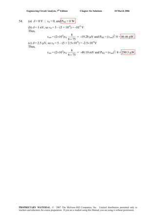
![Engineering Circuit Analysis, 7th
Edition Chapter Six Solutions 10 March 2006
55.
AD549
Writing a single nodal equation at the output, we find that
o
dout
i
inout
R
A-
R
-
0
vvvv
+= [1]
Also, vin – vout = vd, so Eqn. [1] becomes
0 = (vout – vin) Ro + (vout – Avin + Avout) Ri
and
vout =
( )
inv
A R)1(R
ARR
io
io
++
+
To within 4 significant figures (and more, actually), when vin = -16 mV, vout = -16 mV
(this is, after all, a voltage follower circuit).
PROPRIETARY MATERIAL. © 2007 The McGraw-Hill Companies, Inc. Limited distribution permitted only to
teachers and educators for course preparation. If you are a student using this Manual, you are using it without permission.](https://image.slidesharecdn.com/xgizwmivsiwpds00swny-signature-f172ed6d5ea07afd7eea979324352a9b3640d1cd0448b6e1a174e81551e308e0-poli-140819203045-phpapp01/85/Engineering-circuit-analysis_solutions_7ed_-hayt-341-320.jpg)
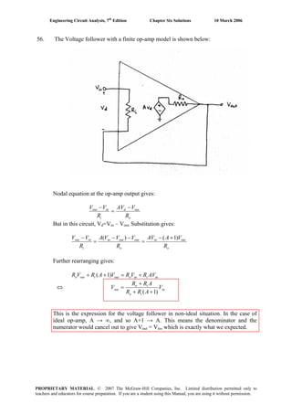
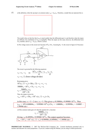
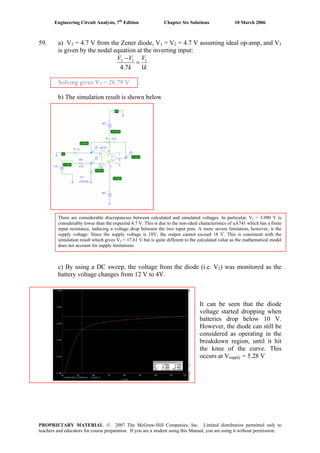
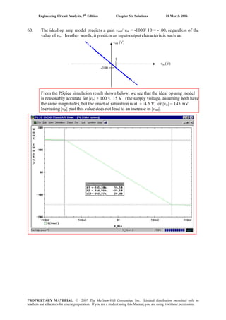
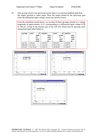
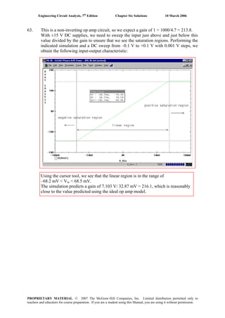
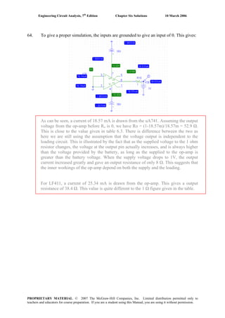
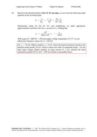
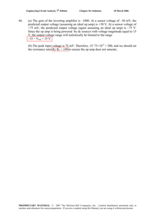
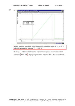
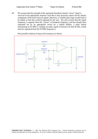
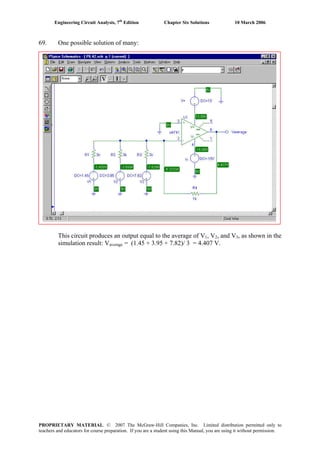
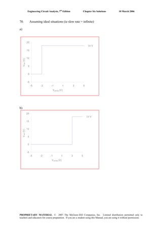
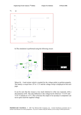
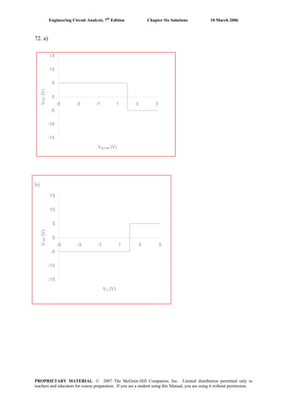
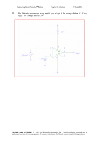
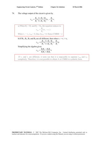
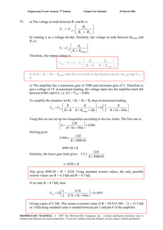
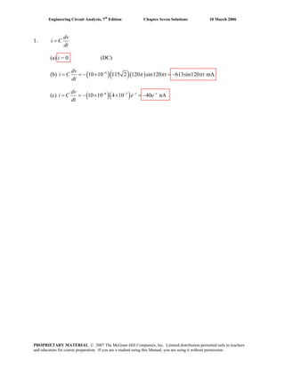
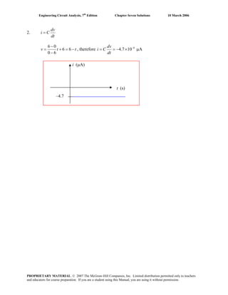
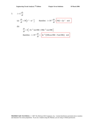
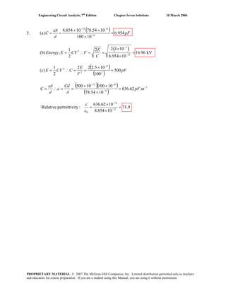
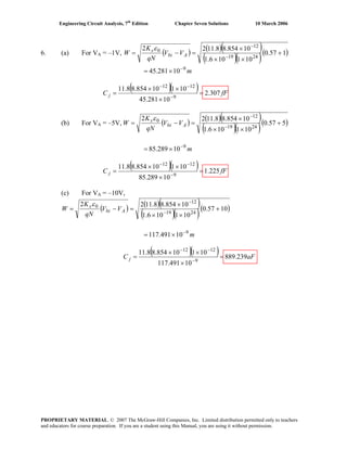
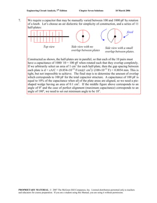
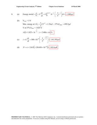
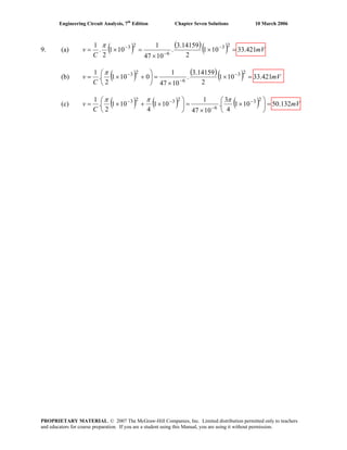
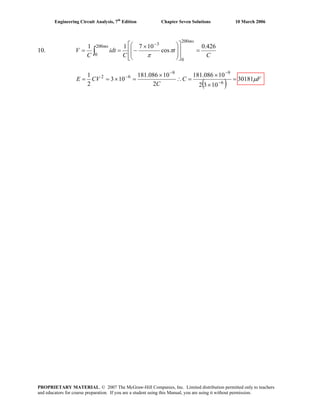
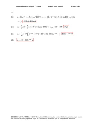
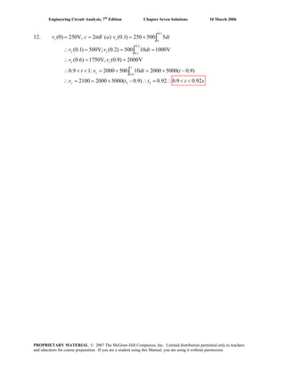
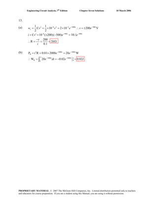
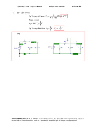
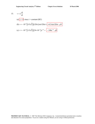
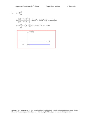
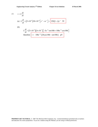
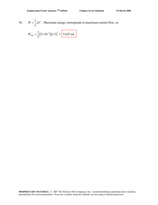
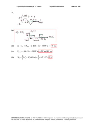
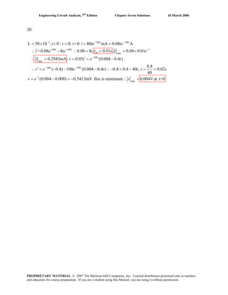
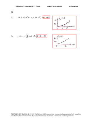
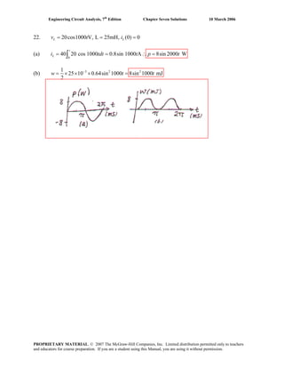
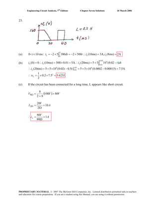
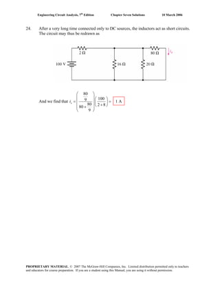
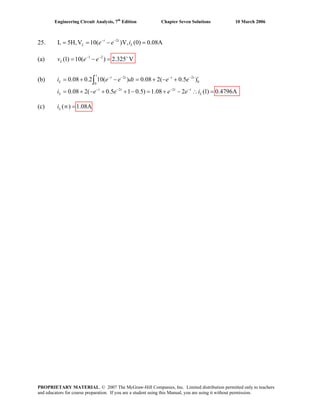
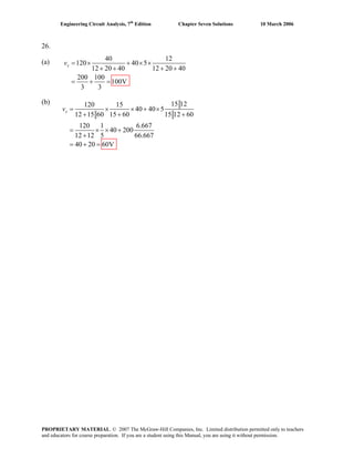
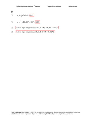
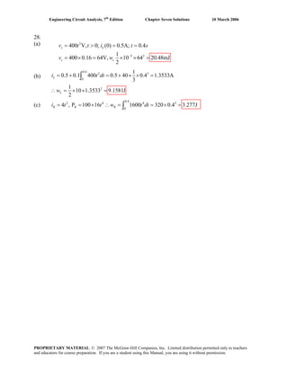
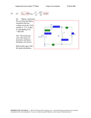
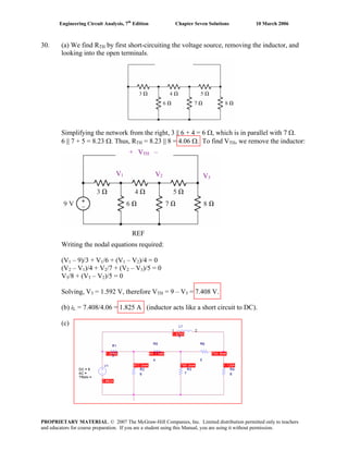
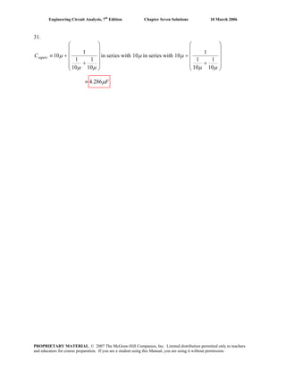
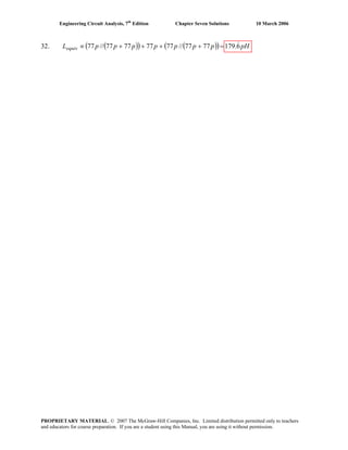
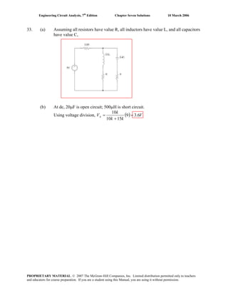
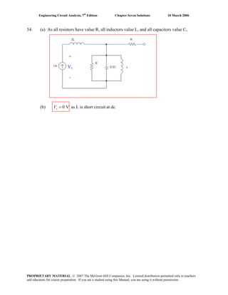
![Engineering Circuit Analysis, 7th
Edition Chapter Seven Solutions 10 March 2006
35. Cequiv = { [(100 n + 40 n) || 12 n] + 75 n} || {7 μ + (2 μ || 12 μ)}
nFCequiv 211.85≡
PROPRIETARY MATERIAL. © 2007 The McGraw-Hill Companies, Inc. Limited distribution permitted only to teachers
and educators for course preparation. If you are a student using this Manual, you are using it without permission.](https://image.slidesharecdn.com/xgizwmivsiwpds00swny-signature-f172ed6d5ea07afd7eea979324352a9b3640d1cd0448b6e1a174e81551e308e0-poli-140819203045-phpapp01/85/Engineering-circuit-analysis_solutions_7ed_-hayt-396-320.jpg)
![Engineering Circuit Analysis, 7th
Edition Chapter Seven Solutions 10 March 2006
36. Lequiv = {[ (17 p || 4 n) + 77 p] || 12 n} + {1 n || (72 p + 14 p)}
pHLequiv 388.172≡
PROPRIETARY MATERIAL. © 2007 The McGraw-Hill Companies, Inc. Limited distribution permitted only to teachers
and educators for course preparation. If you are a student using this Manual, you are using it without permission.](https://image.slidesharecdn.com/xgizwmivsiwpds00swny-signature-f172ed6d5ea07afd7eea979324352a9b3640d1cd0448b6e1a174e81551e308e0-poli-140819203045-phpapp01/85/Engineering-circuit-analysis_solutions_7ed_-hayt-397-320.jpg)
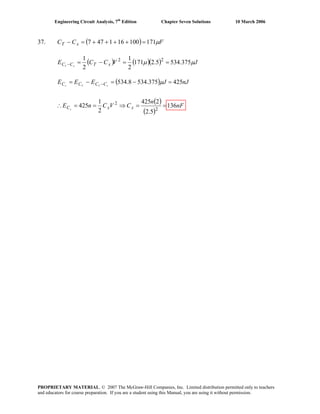
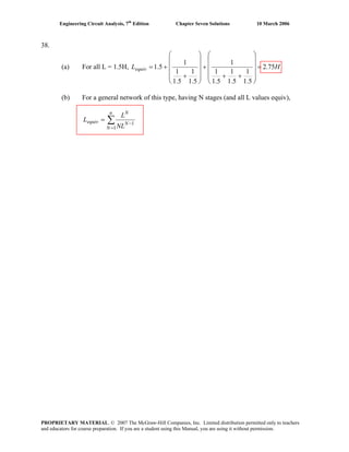
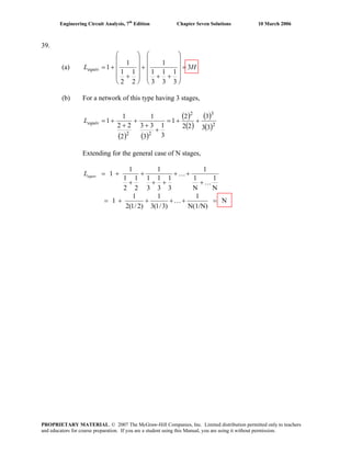
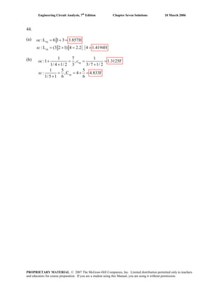
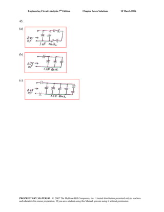
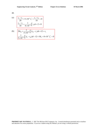
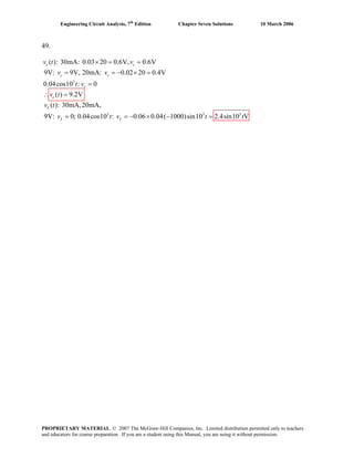
![Engineering Circuit Analysis, 7th
Edition Chapter Seven Solutions 10 March 2006
50. We begin by selecting the bottom node as the reference and assigning four nodal
voltages:
1, 4 Supernode: 20×10-3
e-20t
= ( )∫ ′−×+ −
t
t
tde
0
20
4
321
40V100.02
50
V-V
[1]
and: V1 – V4 = 0.2 Vx or 0.8V1 + 0.2 V2 – V4 = 0 [2]
Node 2:
dt
de t
26-
20
212 V
10
100
40-V
50
V-V
0 ++=
−
[3]
Ref.
V1
V2
V3
V4
PROPRIETARY MATERIAL. © 2007 The McGraw-Hill Companies, Inc. Limited distribution permitted only to teachers
and educators for course preparation. If you are a student using this Manual, you are using it without permission.](https://image.slidesharecdn.com/xgizwmivsiwpds00swny-signature-f172ed6d5ea07afd7eea979324352a9b3640d1cd0448b6e1a174e81551e308e0-poli-140819203045-phpapp01/85/Engineering-circuit-analysis_solutions_7ed_-hayt-411-320.jpg)
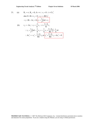
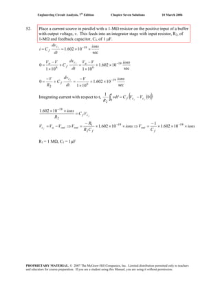
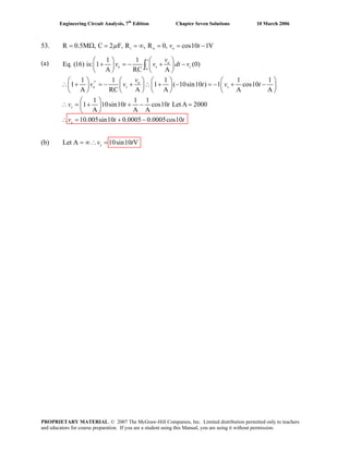
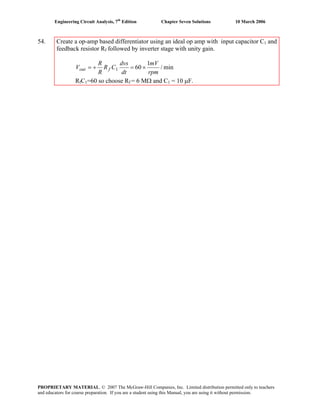
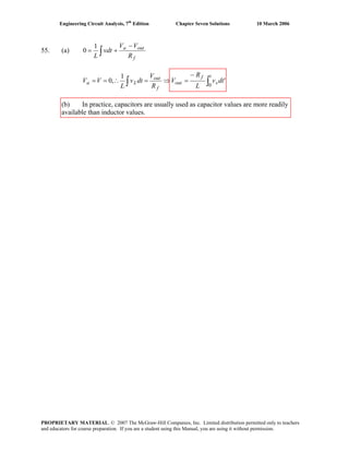
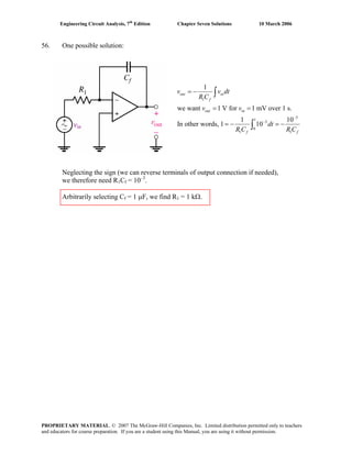
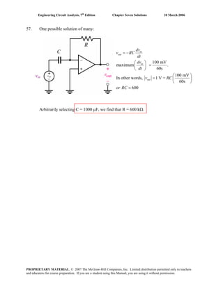
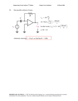
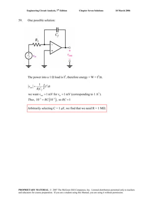
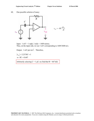
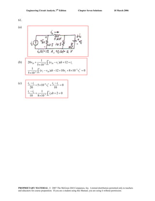
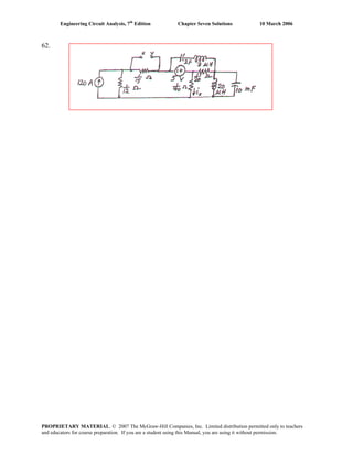
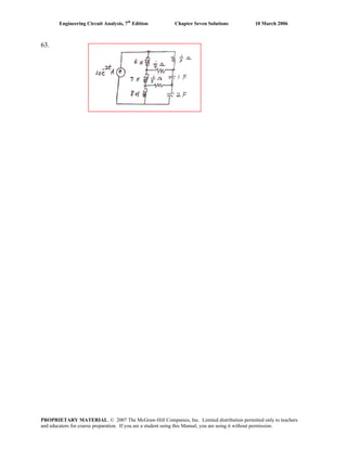
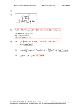
![Engineering Circuit Analysis, 7th
Edition Chapter Seven Solutions 10 March 2006
65.
In creating the dual of the original circuit, we have lost both vs and vout. However, we
may write the dual of the original transfer function: iout/ is. Performing nodal analysis,
)V-(VGV
L
1
21in
0
1
1
S +′= ∫
t
tdi [1]
iout = Aid = GfV2 + Gin (V2 – V1) [2]
Dividing, we find that
)V-(VGV
L
1
VG)V-(VG
21in
0
1
1
2f12in
S
out
+′
+
=
∫
t
tdi
i
PROPRIETARY MATERIAL. © 2007 The McGraw-Hill Companies, Inc. Limited distribution permitted only to teachers
and educators for course preparation. If you are a student using this Manual, you are using it without permission.](https://image.slidesharecdn.com/xgizwmivsiwpds00swny-signature-f172ed6d5ea07afd7eea979324352a9b3640d1cd0448b6e1a174e81551e308e0-poli-140819203045-phpapp01/85/Engineering-circuit-analysis_solutions_7ed_-hayt-426-320.jpg)
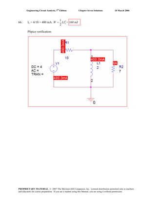
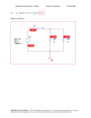
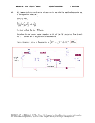
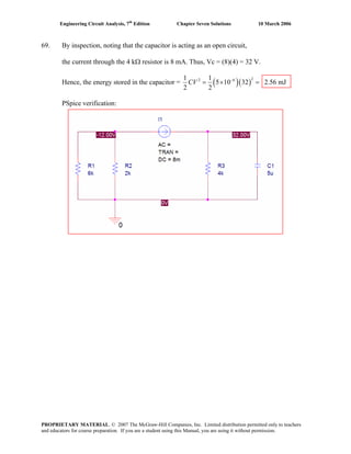
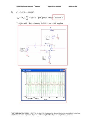
![Engineering Circuit Analysis, 7th
Edition Chapter Seven Solutions 10 March 2006
71. PSpice verification
w = ½ Cv2
= 0.5 (33×10-6
)[5 cos (75×10-2
)]2
= 220.8 μJ. This is in agreement with the
PSpice simulation results shown below.
PROPRIETARY MATERIAL. © 2007 The McGraw-Hill Companies, Inc. Limited distribution permitted only to teachers
and educators for course preparation. If you are a student using this Manual, you are using it without permission.](https://image.slidesharecdn.com/xgizwmivsiwpds00swny-signature-f172ed6d5ea07afd7eea979324352a9b3640d1cd0448b6e1a174e81551e308e0-poli-140819203045-phpapp01/85/Engineering-circuit-analysis_solutions_7ed_-hayt-432-320.jpg)
![Engineering Circuit Analysis, 7th
Edition Chapter Seven Solutions 10 March 2006
72. PSpice verification
w = ½ Li2
= 0.5 (100×10-12
)[5 cos (75×10-2
)]2
= 669.2 pJ. This is in agreement with
the PSpice simulation results shown below.
PROPRIETARY MATERIAL. © 2007 The McGraw-Hill Companies, Inc. Limited distribution permitted only to teachers
and educators for course preparation. If you are a student using this Manual, you are using it without permission.](https://image.slidesharecdn.com/xgizwmivsiwpds00swny-signature-f172ed6d5ea07afd7eea979324352a9b3640d1cd0448b6e1a174e81551e308e0-poli-140819203045-phpapp01/85/Engineering-circuit-analysis_solutions_7ed_-hayt-433-320.jpg)
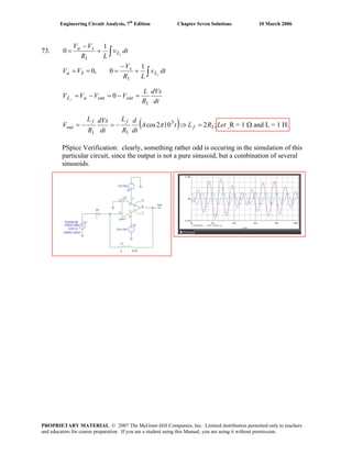
![Engineering Circuit Analysis, 7th
Edition Chapter Seven Solutions 10 March 2006
74. PSpice verification
w = ½ Cv2
= 0.5 (33×10-6
)[5 cos (75×10-2
) - 7]2
= 184.2 μJ. This is in reasonable
agreement with the PSpice simulation results shown below.
PROPRIETARY MATERIAL. © 2007 The McGraw-Hill Companies, Inc. Limited distribution permitted only to teachers
and educators for course preparation. If you are a student using this Manual, you are using it without permission.](https://image.slidesharecdn.com/xgizwmivsiwpds00swny-signature-f172ed6d5ea07afd7eea979324352a9b3640d1cd0448b6e1a174e81551e308e0-poli-140819203045-phpapp01/85/Engineering-circuit-analysis_solutions_7ed_-hayt-435-320.jpg)
![Engineering Circuit Analysis, 7th
Edition Chapter Seven Solutions 10 March 2006
75. PSpice verification
w = ½ Li2
= 0.5 (100×10-12
)[5 cos (75×10-2
) - 7]2
= 558.3 pJ. This is in agreement with
the PSpice simulation results shown below.
PROPRIETARY MATERIAL. © 2007 The McGraw-Hill Companies, Inc. Limited distribution permitted only to teachers
and educators for course preparation. If you are a student using this Manual, you are using it without permission.](https://image.slidesharecdn.com/xgizwmivsiwpds00swny-signature-f172ed6d5ea07afd7eea979324352a9b3640d1cd0448b6e1a174e81551e308e0-poli-140819203045-phpapp01/85/Engineering-circuit-analysis_solutions_7ed_-hayt-436-320.jpg)
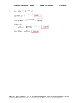
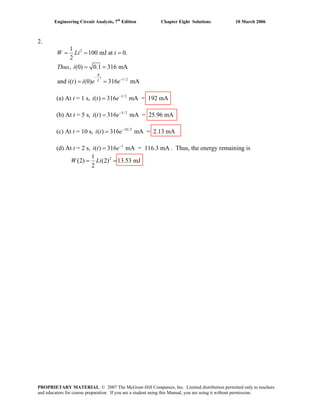
![Engineering Circuit Analysis, 7th
Edition Chapter Eight Solutions 10 March 2006
10. (a)
5 0 [1]
2 so Eq. [1] can be written as
2
5 0 or
2
2.5 2.5 0
R
R
R
R
R
di
L i
dt
v i
v
d
v
L
dt
dv
v
dt
+ =
= −
−⎛ ⎞
⎜ ⎟ −⎛ ⎞⎝ ⎠ − =⎜ ⎟
⎝ ⎠
+ =
(b) Characteristic equation is 2.5s + 2.5 = 0, or s + 1 = 0
Solving, s = –1, ( ) t
Rv t Ae−
=
(c) At t = 0–
, i(0–
) = 5 A = i(0+
). Thus, ( ) 10 , 0t
Rv t e t−
= − >
( )
2
(0 ) 10 6.667 V
3
Rv −
= =
v (0 ) 10 VR
+
= −
1
(1) 10 3.679 VRv e−
= − = −
PROPRIETARY MATERIAL. © 2007 The McGraw-Hill Companies, Inc. Limited distribution permitted only to teachers
and educators for course preparation. If you are a student using this Manual, you are using it without permission.](https://image.slidesharecdn.com/xgizwmivsiwpds00swny-signature-f172ed6d5ea07afd7eea979324352a9b3640d1cd0448b6e1a174e81551e308e0-poli-140819203045-phpapp01/85/Engineering-circuit-analysis_solutions_7ed_-hayt-446-320.jpg)
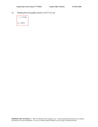
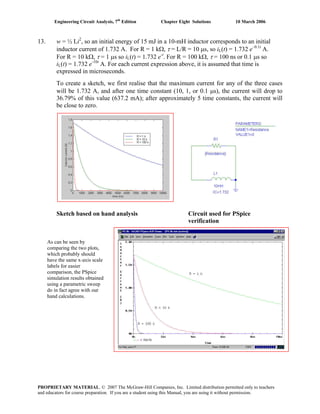
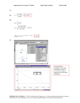
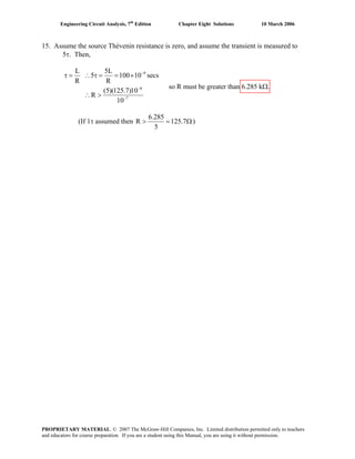
![Engineering Circuit Analysis, 7th
Edition Chapter Eight Solutions 10 March 2006
16. For t < 0, we have a current divider with iL(0-
) = ix(0-
) = 0.5 [ 10 (1/ (1 + 1.5)] mA
= 2 mA. For t > 0, the resistor through which ix flows is shorted, so that ix(t > 0) = 0.
The remaining 1-kΩ resistor and 1-mH inductor network exhibits a decaying current such
that iL(t) = 2e-t/τ
mA where τ = L/R = 1 μS.
(a)
(b)
t (μs)
ix (mA)
2
PROPRIETARY MATERIAL. © 2007 The McGraw-Hill Companies, Inc. Limited distribution permitted only to teachers
and educators for course preparation. If you are a student using this Manual, you are using it without permission.](https://image.slidesharecdn.com/xgizwmivsiwpds00swny-signature-f172ed6d5ea07afd7eea979324352a9b3640d1cd0448b6e1a174e81551e308e0-poli-140819203045-phpapp01/85/Engineering-circuit-analysis_solutions_7ed_-hayt-452-320.jpg)
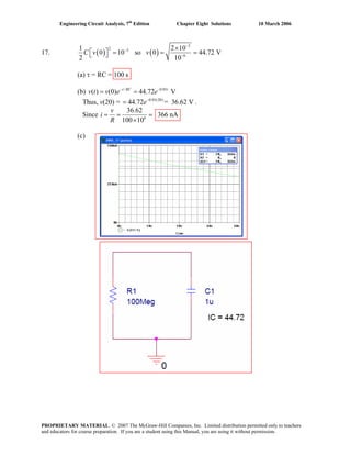
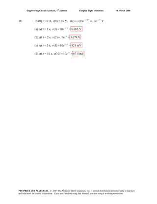

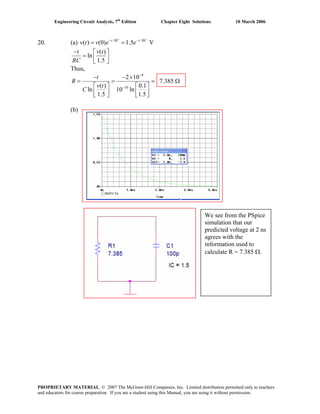
![Engineering Circuit Analysis, 7th
Edition Chapter Eight Solutions 10 March 2006
21. The film acts as an intensity integrator. Assuming that we may model the intensity as a
simple decaying exponential,
φ(t) = φo e-t/ τ
where the time constant τ = RTHC represents the effect of the Thévenin equivalent
resistance of the equipment as it drains the energy stored in the two capacitors, then the
intensity of the image on the film Φ is actually proportional to the integrated exposure:
Φ = dte t
∫
−
timeexposure
0
/
oK τ
φ
where K is some constant. Solving the integral, we find that
Φ = [ ]1-K- time)/osure(exp
o
τ
τφ −
e
The maximum value of this intensity function is –Kφoτ.
With 150 ms yielding an image intensity of approximately 14% of the maximum
observed and the knowledge that at 2 s no further increase is seen leads us to estimate
that 1 – e–150×10–3/ τ
= 0.14, assuming that we are observing single-exponential decay
behavior and that the response speed of the film is not affecting the measurement. Thus,
we may extract an estimate of the circuit time constant as τ = 994.5 ms.
This estimate is consistent with the additional observation that at t = 2 s, the image
appears to be saturated.
With two 50-mF capacitors connected in parallel for a total capacitance of 100 mF, we
may estimate the Thévenin equivalent resistance from τ = RC as Rth = τ / C
= 9.945 Ω.
PROPRIETARY MATERIAL. © 2007 The McGraw-Hill Companies, Inc. Limited distribution permitted only to teachers
and educators for course preparation. If you are a student using this Manual, you are using it without permission.](https://image.slidesharecdn.com/xgizwmivsiwpds00swny-signature-f172ed6d5ea07afd7eea979324352a9b3640d1cd0448b6e1a174e81551e308e0-poli-140819203045-phpapp01/85/Engineering-circuit-analysis_solutions_7ed_-hayt-457-320.jpg)
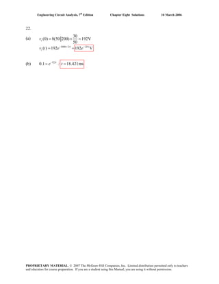
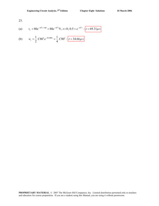
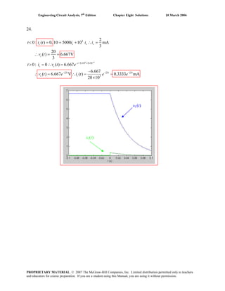
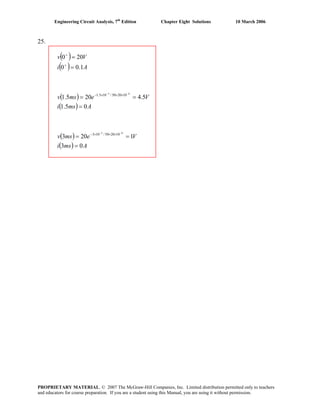
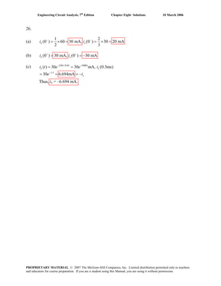
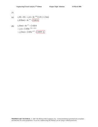
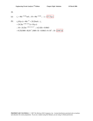
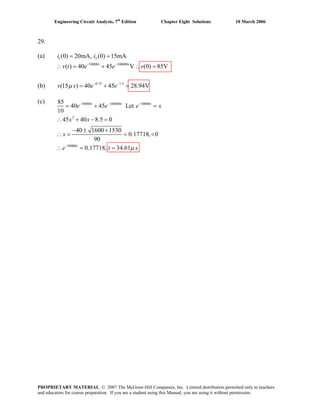
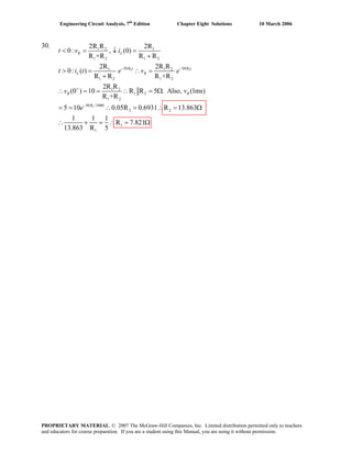
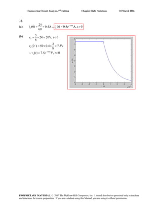
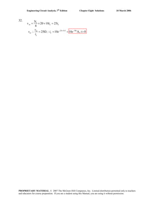
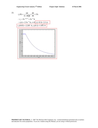
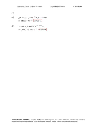
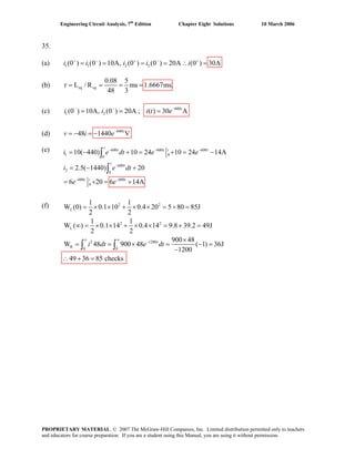
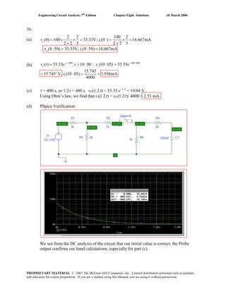
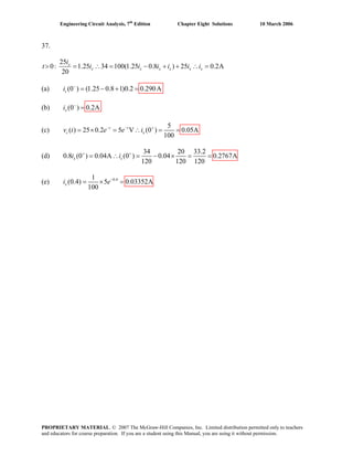
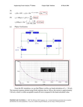
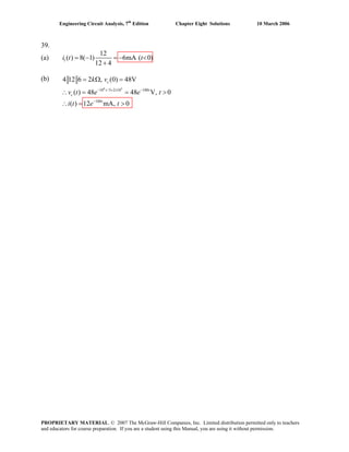
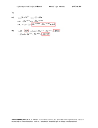
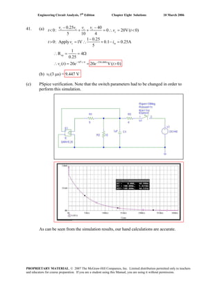
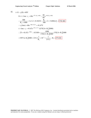
![Engineering Circuit Analysis, 7th
Edition Chapter Eight Solutions 10 March 2006
43.
(a) With the switch closed, define a nodal voltage V1 at the top of the 5-kΩ resistor.
Then,
0 = (V1 – 100)/ 2 + (V1 – VC)/ 3 + V1/ 5 [1]
0 = VC/ 10 + (VC – V1)/ 3 + (VC – 100) [2]
Solving, we find that VC = vC(0-
) = 99.76 V.
(b)
7
10 /3939 2539
0: R 10 6.5 3.939 87.59 87.59 V( 0)− −
> = = Ω∴ = = >t t
eq ct k v e e t
PROPRIETARY MATERIAL. © 2007 The McGraw-Hill Companies, Inc. Limited distribution permitted only to teachers
and educators for course preparation. If you are a student using this Manual, you are using it without permission.](https://image.slidesharecdn.com/xgizwmivsiwpds00swny-signature-f172ed6d5ea07afd7eea979324352a9b3640d1cd0448b6e1a174e81551e308e0-poli-140819203045-phpapp01/85/Engineering-circuit-analysis_solutions_7ed_-hayt-479-320.jpg)
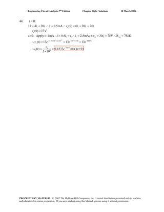
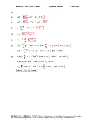
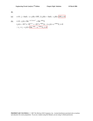
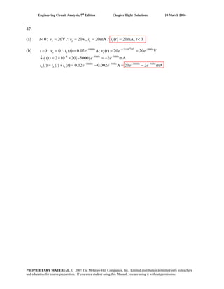
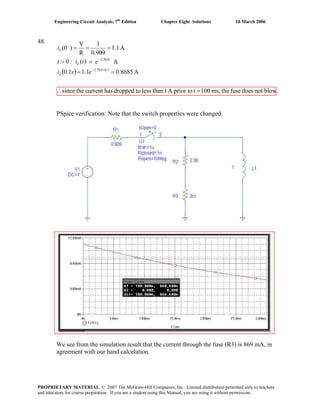
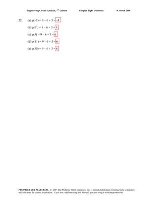
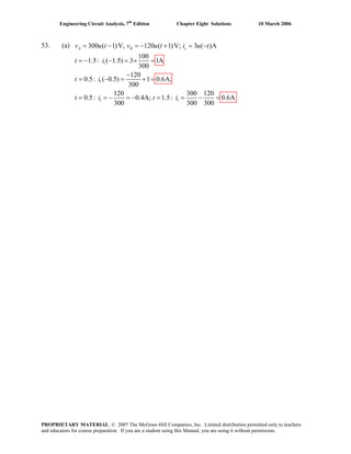
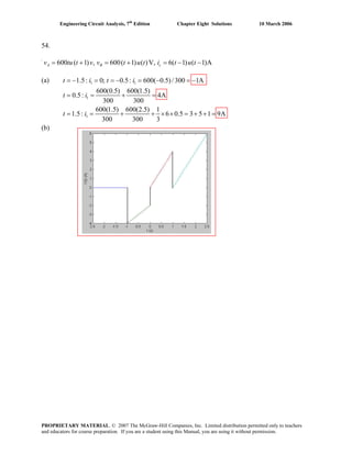
![Engineering Circuit Analysis, 7th
Edition Chapter Eight Solutions 10 March 2006
55.
(a) 2 ( 1) 3 (1) 4 (3) 3 4 1u u u− − + = − + =
(b) [5 u u− (2)] [2 (1)] [1 ( 1)]
4 3 1 12
u+ − −
= × × =
(c) (1) 1
4 (1) 4 1.4715u
e u e− − +
= =
PROPRIETARY MATERIAL. © 2007 The McGraw-Hill Companies, Inc. Limited distribution permitted only to teachers
and educators for course preparation. If you are a student using this Manual, you are using it without permission.](https://image.slidesharecdn.com/xgizwmivsiwpds00swny-signature-f172ed6d5ea07afd7eea979324352a9b3640d1cd0448b6e1a174e81551e308e0-poli-140819203045-phpapp01/85/Engineering-circuit-analysis_solutions_7ed_-hayt-491-320.jpg)
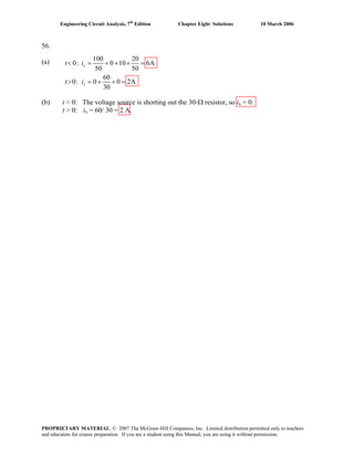
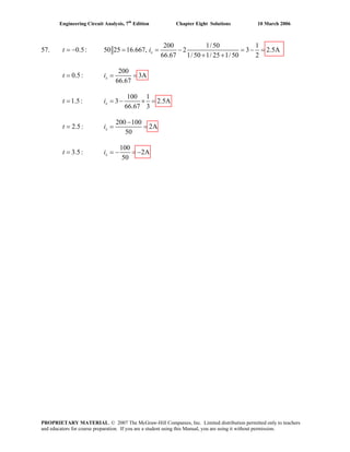
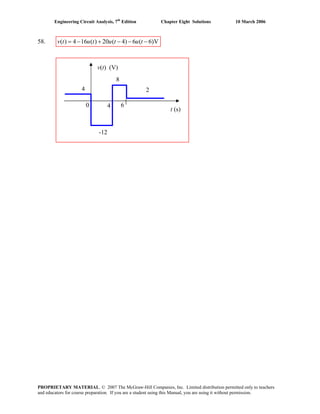
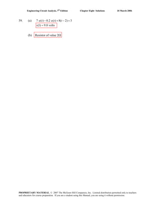
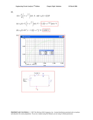
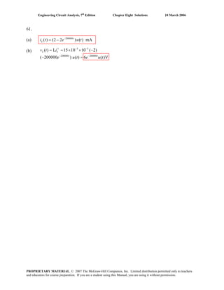
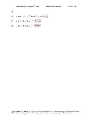
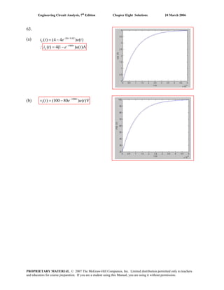
![Engineering Circuit Analysis, 7th
Edition Chapter Eight Solutions 10 March 2006
64. (a) 0 W
(b) The total inductance is 30 || 10 = 7.5 mH. The Thévenin equivalent resistance is
12 || 11 = 5.739 kΩ. Thus, the circuit time constant is L/R = 1.307 μs. The final value of
the total current flowing into the parallel inductor combination is 50/12 mA = 4.167 mA.
This will be divided between the two inductors, so that i(∞) = (4.167)(30)/ (30 + 10) =
3.125 mA.
We may therefore write i(t) = 3.125[1 – e-106t/ 1.307
] A. Solving at t = 3 μs,
we find 2.810 A.
(c) PSpice verification
We see from the Probe output that our hand calculations are correct by verifying using
the cursor tool at t = 3 μs.
PROPRIETARY MATERIAL. © 2007 The McGraw-Hill Companies, Inc. Limited distribution permitted only to teachers
and educators for course preparation. If you are a student using this Manual, you are using it without permission.](https://image.slidesharecdn.com/xgizwmivsiwpds00swny-signature-f172ed6d5ea07afd7eea979324352a9b3640d1cd0448b6e1a174e81551e308e0-poli-140819203045-phpapp01/85/Engineering-circuit-analysis_solutions_7ed_-hayt-500-320.jpg)
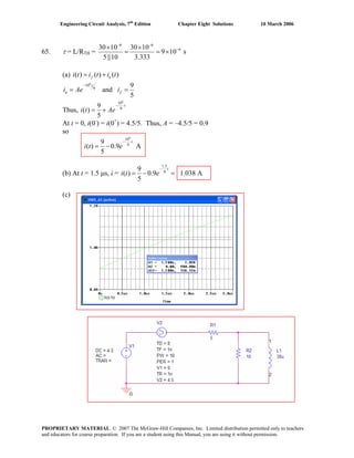
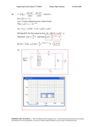
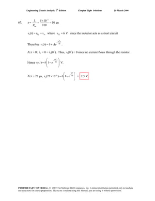

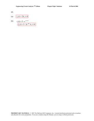
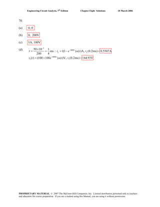
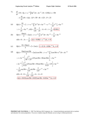
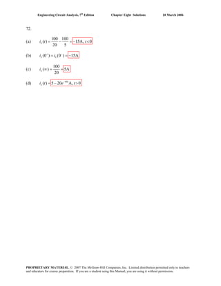
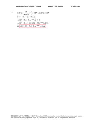
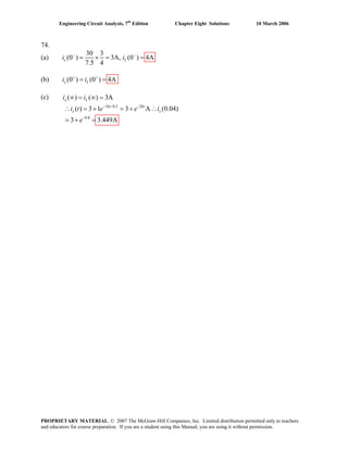
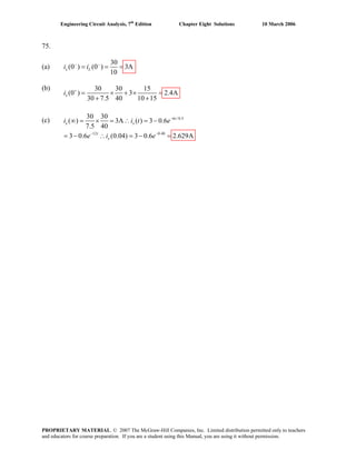
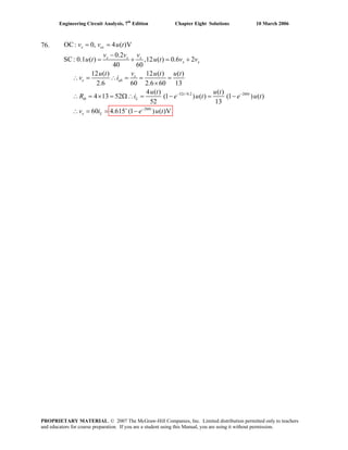
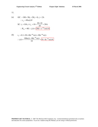
![Engineering Circuit Analysis, 7th
Edition Chapter Eight Solutions 10 March 2006
78. (5)(2) 10 seqR Cτ = = =
Thus, .0.2
( ) t
nv t Ae−
=
.0.1 5t t
n fv v v Ae Be− −
= + = +
At t = 0, v(0) = 0 since no source exists prior to t = 0. Thus, A + B = 0 [1].
As t , . We need another equation.→ ∞ ( ) 0v ∞ →
( )
0
4.7 4.7 4.7
(0) 2 therefore or 0.1 5
5 5t
dv dv
i C A B
dt dt +
=
= = = − − =
5
[2]
Solving our two equations, we find that A = –B = 0.192.
Thus, v t ( )0.1 5
( ) 0.192 t t
e e− −
= −
PROPRIETARY MATERIAL. © 2007 The McGraw-Hill Companies, Inc. Limited distribution permitted only to teachers
and educators for course preparation. If you are a student using this Manual, you are using it without permission.](https://image.slidesharecdn.com/xgizwmivsiwpds00swny-signature-f172ed6d5ea07afd7eea979324352a9b3640d1cd0448b6e1a174e81551e308e0-poli-140819203045-phpapp01/85/Engineering-circuit-analysis_solutions_7ed_-hayt-514-320.jpg)
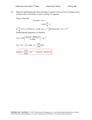
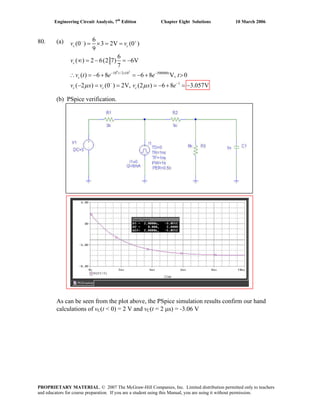
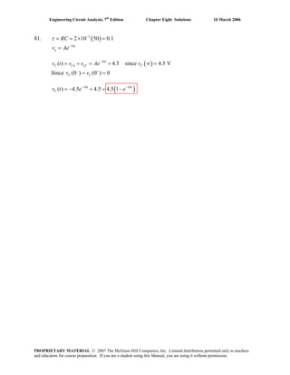
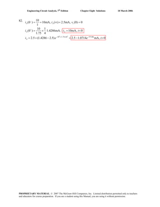
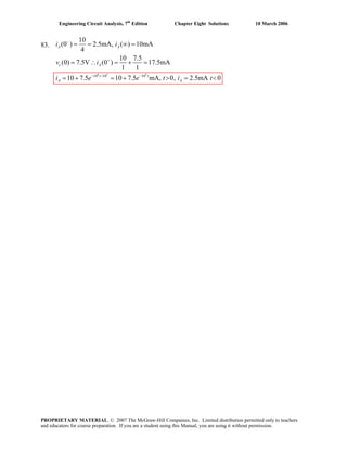
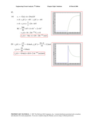
![Engineering Circuit Analysis, 7th
Edition Chapter Eight Solutions 10 March 2006
88.
(a) For t < 0, there are no active sources, and so vC = 0.
For 0 < t < 1, only the 40-V source is active. Rth = 5k || 20 k = 4 kΩ and hence
τ = Rth C = 0.4 s. The “final” value (assuming no other source is ever added) is found
by voltage division to be vC(∞) = 40(20)/(20 + 5) = 32 V. Thus, we may write
vC(t) = 32 + [0 – 32] e–t/ 0.4
V = 32(1 – e-2.5t
) V.
For t > 1, we now have two sources operating, although the circuit time constant remains
unchanged. We define a new time axis temporarily: t' = t – 1. Then vC(t' = 0+
) =
vC(t = 1) = 29.37 V. This is the voltage across the capacitor when the second source
kicks on. The new final voltage is found to be vC(∞) = 40(20)/ (20 + 5) +
100(5)/ (20 + 5) = 52 V.
Thus, vC(t') = 52 + [29.37 – 52] e-2.5t'
= 52 – 22.63 e-2.5(t – 1)
V.
For t < 0,
vC = 0.
We see from the simulation results that
our hand calculations and sketch are
indeed correct.
(b)
(c)
PROPRIETARY MATERIAL. © 2007 The McGraw-Hill Companies, Inc. Limited distribution permitted only to teachers
and educators for course preparation. If you are a student using this Manual, you are using it without permission.](https://image.slidesharecdn.com/xgizwmivsiwpds00swny-signature-f172ed6d5ea07afd7eea979324352a9b3640d1cd0448b6e1a174e81551e308e0-poli-140819203045-phpapp01/85/Engineering-circuit-analysis_solutions_7ed_-hayt-524-320.jpg)
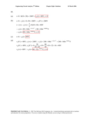
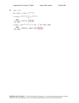
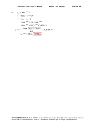
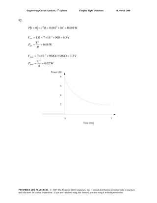
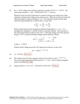
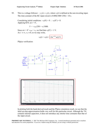
![Engineering Circuit Analysis, 7th
Edition Chapter Eight Solutions 10 March 2006
96. For t < 0, the current source is an open circuit and so i1 = 40/ 50 = 0.8 A.
The current through the 5-Ω resistor is [40 – 10(0.8)]/ 5 = 7.2 A, so the inductor current
is equal to – 7.2 A
PSpice Simulation
From the PSpice simulation, we see that our t < 0 calculation is indeed correct, and find
that the inductor current at t = 50 ms is 7.82 A.
PROPRIETARY MATERIAL. © 2007 The McGraw-Hill Companies, Inc. Limited distribution permitted only to teachers
and educators for course preparation. If you are a student using this Manual, you are using it without permission.](https://image.slidesharecdn.com/xgizwmivsiwpds00swny-signature-f172ed6d5ea07afd7eea979324352a9b3640d1cd0448b6e1a174e81551e308e0-poli-140819203045-phpapp01/85/Engineering-circuit-analysis_solutions_7ed_-hayt-532-320.jpg)
![Engineering Circuit Analysis, 7th
Edition Chapter Eight Solutions 10 March 2006
97. (a)
And we may write vo(t) = -0.2[1 + e-20×103t
]u(t) V.
(b) PSpice verification:
20,000
1 4
7 20,000 20,000
4
20,000
3 20,000
20,000 20,000
4
0 (virtual gnd) ( )A
10
4
10 0.2
10
( ) 0.2(1 ) ( )
( ) 10 ( ) 0.4 ( )V
( ) ( ) ( ) ( 0.2 0.2 0.4 ) ( )
t
t
t t t
c o
o
t
c
t
R
t t
o c R
v i e u t
v e dt e
v t e u t
v t i t e u t
v t v t v t e e u t
−
− −
−
−
− −
= ∴ =
∴ = = −
∴ = −
∴ = =
∴ = − − = − + −
∫
We can see from the simulation result that our ideal op amp approximation is not
providing a great deal of accuracy in modeling the transient response of an op amp in this
particular circuit; the output was predicted to be negative for t > 0.
PROPRIETARY MATERIAL. © 2007 The McGraw-Hill Companies, Inc. Limited distribution permitted only to teachers
and educators for course preparation. If you are a student using this Manual, you are using it without permission.](https://image.slidesharecdn.com/xgizwmivsiwpds00swny-signature-f172ed6d5ea07afd7eea979324352a9b3640d1cd0448b6e1a174e81551e308e0-poli-140819203045-phpapp01/85/Engineering-circuit-analysis_solutions_7ed_-hayt-533-320.jpg)
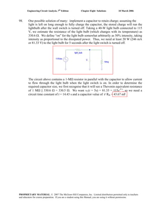
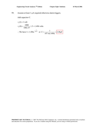
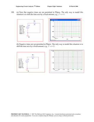
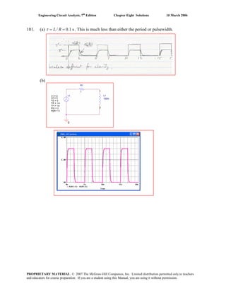
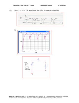
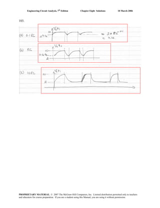
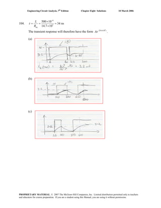
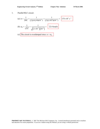
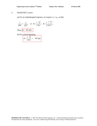
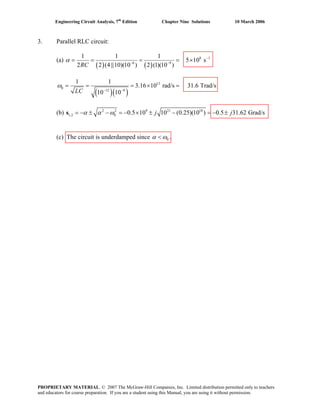
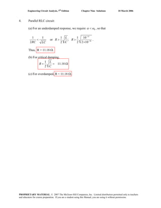
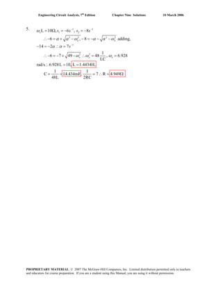
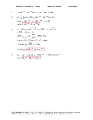
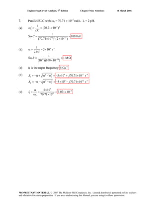
![Engineering Circuit Analysis, 7th
Edition Chapter Nine Solutions 10 March 2006
8. Given: 2 1
4 ,
2
= α =L R C
RC
Show that is a solution to1 2( ) ( )−α
= +t
v t e At A
2
2
1 1
0 [+ + =
d v dv
C v
dt R dt L
1]
1 1 2
1 1 2
2
1 1 2 12
1 2 1 1
1 2 1
( ) ( )
( )
( )( )
( )
(2 ) [3]
−α −α
−α
−α −α
−α
−α
= − α +
= − α − α
= − α − α −α − α
= −α − α + − α
= −α − α − α
t t
t
t t
t
t
dv
e A e At A
dt
A At A e
d v
A At A e Ae
dt
A A A At e
A A At e
[2]
Substituting Eqs. [2] and [3] into Eq. [1], and using the information initially provided,
2
1 1 2
1 2 1 22 2
1 1 1
(2 ) ( ) ( )
2 2
1 1
( ) ( )
2 4
0
−α −α −α
−α −α
⎛ ⎞
− + + +⎜ ⎟
⎝ ⎠
− + + +
=
t t
t t
A e At A e A e
RC RC RC
At A e At A e
RC R C
1
t
Thus, is in fact a solution to the differential equation.1 2( ) ( )−α
= +t
v t e At A
Next, with 2(0) 16= =v A
and 1 2 1
0
( ) ( 16 )
=
= − α = − α =
t
dv
A A A
dt
4
we find that 1 4 16= + αA
PROPRIETARY MATERIAL. © 2007 The McGraw-Hill Companies, Inc. Limited distribution permitted only to teachers
and educators for course preparation. If you are a student using this Manual, you are using it without permission.](https://image.slidesharecdn.com/xgizwmivsiwpds00swny-signature-f172ed6d5ea07afd7eea979324352a9b3640d1cd0448b6e1a174e81551e308e0-poli-140819203045-phpapp01/85/Engineering-circuit-analysis_solutions_7ed_-hayt-548-320.jpg)
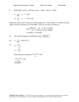
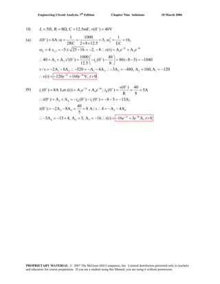
![Engineering Circuit Analysis, 7th
Edition Chapter Nine Solutions 10 March 2006
11. (a)
3
4
1 1 10 1
10 1.581
2 2 10 2
C
L
R
C
−
−
= = = = Ω
Therefore
R = 0.1RC = 158.1 mΩ
(b) 4 1 3
0
1 1
3.162 10 s and 3.162 10 rad/s
2RC LC
α ω−
= = × = = ×
Thus, 2 2 1 4
1,2 0 158.5 s and 6.31 10 sα α ω 1− −
= −s ± − = − − ×
Ae A e− − ×
= +
v v− + − +
= = = =
So we may write i t
4
158.5 6.31 10
1 2( ) t t
With i i(0 ) (0 ) 4 A and (0 ) (0 ) 10 V
A1+ A2 = 4 [1]
Noting
0
(0 ) 10
t
di
v L
dt
+
=
= =
[2]( )3 4
1 210 158.5 6.31 10 10A A−
− − × =
Solving Eqs. [1] and [2] yields A1 = 4.169 A and A2 = –0.169 A
So that
4
158.5 6.31 10
( ) 4.169 0.169 At t
i t e e− − ×
= −
PROPRIETARY MATERIAL. © 2007 The McGraw-Hill Companies, Inc. Limited distribution permitted only to teachers
and educators for course preparation. If you are a student using this Manual, you are using it without permission.](https://image.slidesharecdn.com/xgizwmivsiwpds00swny-signature-f172ed6d5ea07afd7eea979324352a9b3640d1cd0448b6e1a174e81551e308e0-poli-140819203045-phpapp01/85/Engineering-circuit-analysis_solutions_7ed_-hayt-551-320.jpg)
![Engineering Circuit Analysis, 7th
Edition Chapter Nine Solutions 10 March 2006
12. (a) 1
0
1 1
500 s and 100 rad/s
2RC LC
α ω−
= = = =
Thus, 2 2 1
1,2 0 10.10 s and 989.9 sα α ω 1− −
= −s ± − = − −
Ae A e− −
= +
v v− + − +
= = = =
So we may write i t [1]10.1 989.9
1 2( ) t t
R
With i i(0 ) (0 ) 2 mA and (0 ) (0 ) 0
A1+ A2 = 0 [2]
We need to find
0
R
t
di
dt =
. Note that
( ) 1Rdi t dv
dt R dt
= [3] and C R
dv
i C i i
dt
= = − − .
Thus, 3 3
0
(0 )
(0 ) (0 ) (0 ) 2 10 2 10C R
t
dv v
i C [4]i i
dt R+
+
+ + + − −
=
= = − − = − × − = − ×
Therefore, we may write based on Eqs. [3] and [4]:
0
(50)( 0.04) 2R
t
di
dt =
= − = − [5]. Taking the derivative of Eq. [1] and combining with
Eq. [5] then yields: s s [6].1 1 2 2 2A A+ = −
Solving Eqs. [2] and [6] yields A1 = 2.04− mA and A2 = 2.04 mA
So that ( )10.1 989.9
( ) 2.04 mAt t
Ri t e e− −
= − −
(b) (c) We see that the simulation agrees.
PROPRIETARY MATERIAL. © 2007 The McGraw-Hill Companies, Inc. Limited distribution permitted only to teachers
and educators for course preparation. If you are a student using this Manual, you are using it without permission.](https://image.slidesharecdn.com/xgizwmivsiwpds00swny-signature-f172ed6d5ea07afd7eea979324352a9b3640d1cd0448b6e1a174e81551e308e0-poli-140819203045-phpapp01/85/Engineering-circuit-analysis_solutions_7ed_-hayt-552-320.jpg)
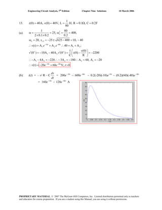
![Engineering Circuit Analysis, 7th
Edition Chapter Nine Solutions 10 March 2006
14. (a) 8 1 5
0
1 1
6.667 10 s and 10 rad/s
2RC LC
α ω−
= = × = =
Thus, 2 2 1 9
1,2 0 7.5 s and 1.333 10 sα α ω 1− −
= −s . So we may write
[1] With i i ,
± − = − − ×
t×
v v− + − +
= = = =
9
7.5 1.333 10
1 2( ) t
Ci t Ae A e− −
= + (0 ) (0 ) 0 A and (0 ) (0 ) 2 V
6
6
2
(0 ) (0 ) 0.133 10
15 10
C Ri i+ +
−
= − = − = − ×
×
so that
A1+ A2 = –0.133×10⁶
[2]
We need to find
0
R
t
di
dt =
. We know that 6
6
0 0
2
2 so 10
2 10t t
di di
L
dt dt −
= =
= =
×
= . Also,
1
and R
C
didv dv
C i
dt dt R dt
= = so ( )9
7.5 1.333 10
1 2
1 t tCR idi
Ae A e
dt CR CR
− − ×
= = + .
Using 9 6
1 2 1
0
1
0 so 7.5 1.33 10 10 ( )C CR
t
di didi
2A A A A
dt dt dt dt CR=
= = − − × = − − +
di
+ + [3]
Solving Eqs. [2] and [3] yields A1 = 0.75− mA and A2 = –0.133 MA (very different!)
So that ( )9
3 7.5 6 1.333 10
( ) 0.75 10 0.133 10 At t
Ci t e e− − − ×
= − × + ×
(b)
PROPRIETARY MATERIAL. © 2007 The McGraw-Hill Companies, Inc. Limited distribution permitted only to teachers
and educators for course preparation. If you are a student using this Manual, you are using it without permission.](https://image.slidesharecdn.com/xgizwmivsiwpds00swny-signature-f172ed6d5ea07afd7eea979324352a9b3640d1cd0448b6e1a174e81551e308e0-poli-140819203045-phpapp01/85/Engineering-circuit-analysis_solutions_7ed_-hayt-554-320.jpg)
![Engineering Circuit Analysis, 7th
Edition Chapter Nine Solutions 10 March 2006
15. (a) 1
0
1 1
0.125 s and 0.112 rad/s
2RC LC
α ω−
= = = =
Thus, 2 2 1
1,2 0 0.069 s and 0.181 sα α ω 1− −
= −s . So we may write
v t [1]
± − = − −
Ae A e− −
= +
v v− + − +
= = − = =
0.069 0.181
1 2( ) t t
With i i ,(0 ) (0 ) 8 A and (0 ) (0 ) 0C C
A1+ A2 = 0 [2]
We need to find
0
R
t
di
dt =
. We know that
0.069 0.181
1 2( ) 4 0.069 0.181t t
C
dv
i t C Ae A e
dt
− −
⎡ ⎤= = − −⎣ ⎦ . So,
[ ]1 2(0) 4 0.069 0.181 8Ci A [3]A= − − = −
Solving Eqs. [2] and [3] yields A1 = 17.89− V and A2 = 17.89 V
So that 0.069 0.181
( ) 17.89 Vt t
v t e e− −
⎡ ⎤= − −⎣ ⎦
(b) 0.069 0.181
1.236 8.236t t
e e
dt
− −
−
dv
= . We set this equal to 0 and solve for tm:
0.069
0.112
0.181
3.236
1.236
m
m
m
t
t
t
e
e
e
−
−
= = , so that tm = 8.61 s.
Substituting into our expression for the voltage, the peak value is
v(8.61) = –6.1 V
(c) The simulation agrees with the analytic results.
PROPRIETARY MATERIAL. © 2007 The McGraw-Hill Companies, Inc. Limited distribution permitted only to teachers
and educators for course preparation. If you are a student using this Manual, you are using it without permission.](https://image.slidesharecdn.com/xgizwmivsiwpds00swny-signature-f172ed6d5ea07afd7eea979324352a9b3640d1cd0448b6e1a174e81551e308e0-poli-140819203045-phpapp01/85/Engineering-circuit-analysis_solutions_7ed_-hayt-555-320.jpg)
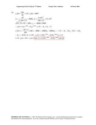
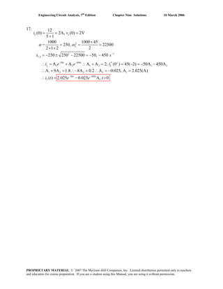
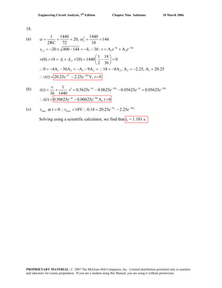
![Engineering Circuit Analysis, 7th
Edition Chapter Nine Solutions 10 March 2006
19. Referring to Fig. 9.43,
L = 1250 mH
so Since α > ωo, this circuit is over damped.
1
1 4rad/s
1
5
2
−
ω = =
α = =
o
LC
s
RC
The capacitor stores 390 J at t = 0−
:
2
1
1
2
2
So (0 ) 125 V (0 )+
=
= = =
c c
c
c c
W C v
W
v v
C
The inductor initially stores zero energy,
so
2 2
1,2
(0 ) (0 ) 0
5 3 8, 2
− +
= =
= −α ± α − ω = − ± = − −
L L
o
i i
S
Thus, 8 2
( ) − −
= +t t
v t Ae Be
Using the initial conditions, (0) 125 [1]= = +v A B
3 8 2
3
(0 )
(0 ) (0 ) (0 ) 0 (0 ) 0
2
(0 ) 125
So (0 ) 62.5 V
2 2
50 10 [ 8 2 ]
(0 ) 62.5 50 10 (8 2 ) [2]
+
+ + + +
+
+
− − −
+ −
+ + = + + =
= − = − = −
= = × − −
= − = − × +
L R c c
c
t t
c
c
v
i i i i
v
i
dv
i C Ae Be
dt
i A B
Solving Eqs. [1] and [2], A = 150 V
B = −25 V
Thus, 8 2
( ) 166.7 41.67 , 0− −
= − >t t
v t e e t
PROPRIETARY MATERIAL. © 2007 The McGraw-Hill Companies, Inc. Limited distribution permitted only to teachers
and educators for course preparation. If you are a student using this Manual, you are using it without permission.](https://image.slidesharecdn.com/xgizwmivsiwpds00swny-signature-f172ed6d5ea07afd7eea979324352a9b3640d1cd0448b6e1a174e81551e308e0-poli-140819203045-phpapp01/85/Engineering-circuit-analysis_solutions_7ed_-hayt-559-320.jpg)
![Engineering Circuit Analysis, 7th
Edition Chapter Nine Solutions 10 March 2006
20. (a) We want a response 4 6− −
= +t t
v Ae Be
1
2 2 2
1
2 2
2
1
5
2
4 5 25
6 5 25
−
α = =
= −α + α − ω = − = − + − ω
= −α − α − ω = − = − − − ω
o o
o o
s
RC
S
S 2
Solving either equation, we obtain ωo = 4.899 rad/s
Since 2
2
1 1
, 833.3 mHω = = =
ω
o
o
L
LC C
+ +
= =R c(b) If .i i(0 ) 10 A and (0 ) 15 A, find A and B
with
3 4 6
3
4 6
(0 ) 10 A, (0 ) (0 ) (0 ) 20 V
(0) 20 [1]
50 10 ( 4 6 )
(0 ) 50 10 ( 4 6 ) 15 [2]
Solving, 210 V, 190 V
Thus, 210 190 , 0
+ + + +
− − −
+ −
− −
= = = =
= + =
= = × − −
= × − − =
= = −
= − >
R R c
t t
c
c
t t
i v v v
v A B
dv
i C Ae Be
dt
i A B
A B
v e e t
PROPRIETARY MATERIAL. © 2007 The McGraw-Hill Companies, Inc. Limited distribution permitted only to teachers
and educators for course preparation. If you are a student using this Manual, you are using it without permission.](https://image.slidesharecdn.com/xgizwmivsiwpds00swny-signature-f172ed6d5ea07afd7eea979324352a9b3640d1cd0448b6e1a174e81551e308e0-poli-140819203045-phpapp01/85/Engineering-circuit-analysis_solutions_7ed_-hayt-560-320.jpg)
![Engineering Circuit Analysis, 7th
Edition Chapter Nine Solutions 10 March 2006
21. Initial conditions:
50
(0 ) (0 ) 0 (0 ) 2 A
25
− + +
= = = =L L Ri i i
(a) (0 ) (0 ) 2(25) 50 V+ −
= = =c cv v
(b) (0 ) (0 ) (0 ) 0 2 2 A+ + +
= − − = − = −c L Ri i i
(c) t > 0: parallel (source-free) RLC circuit
11
4000
2
1
3464 rad/s
−
α = =
ω = =o
s
RC
LC
Since α > ω0, this system is overdamped. Thus,
Solving, we find A = −25 and B = 75
so that 2000 6000
( ) 25 75 , 0− −
= − + >t t
cv t e e t
(d)
(e) 2000 6000
25 75 0 274.7− −
− + = ⇒ =t t
e e μst
using a scientific calculator
2000 6000
6 2000 6000
( )
(5 10 )( 2000 6000 )
(0 ) 0.01 0.03 2 [1]
and (0 ) 50 [2]
− −
− − −
+
+
= +
= = × − −
= − − = −
= + =
t t
c
t t
c
c
c
v t Ae Be
dv
i C Ae Be
dt
i A B
v A B
2 2
2000, 6000
= −α ± α − ω
= − −
o
s1,2
(f) max
25 75 50 V= − + =cv
So, solving |− +2000 6000
25 75− −s st t
e e | = 0.5 in view of the graph in part (d),
we find ts = 1.955 ms using a scientific calculator’s equation solver routine.
PROPRIETARY MATERIAL. © 2007 The McGraw-Hill Companies, Inc. Limited distribution permitted only to teachers
and educators for course preparation. If you are a student using this Manual, you are using it without permission.](https://image.slidesharecdn.com/xgizwmivsiwpds00swny-signature-f172ed6d5ea07afd7eea979324352a9b3640d1cd0448b6e1a174e81551e308e0-poli-140819203045-phpapp01/85/Engineering-circuit-analysis_solutions_7ed_-hayt-561-320.jpg)
![Engineering Circuit Analysis, 7th
Edition Chapter Nine Solutions 10 March 2006
22. Due to the presence of the inductor, (0 ) 0−
=cv . Performing mesh analysis,
1 2
2 1 2
1 2
9 2 2 0 [1]
2 2 3 7 0 [2]
and
− + − =
− + + =
− =
A
A
i i
i i i i
i i i
4.444 H
→i2→i1
Rearranging, we obtain 2i1 – 2i2 = 0 and –4i1 + 6 i2 = 0. Solving, i1 = 13.5 A and i2 = 9 A.
(a) 1 2 2(0 ) 4.5 A and (0 ) 9 A− −
= − = = =A Li i i i i
(b) t > 0:
(0 ) 7 (0 ) 3 (0 ) 2 (0 ) 0
so, (0 ) 0
+ + + +
+
− + − +
=
c A A A
A
v i i i
i
(c) due to the presence of the inductor.(0 ) 0−
=cv
=
around left mesh:
4.444 H
(d)
1 A
7 3(1) 2 0
6
6 V 6
1
− + − + =
= ∴ = = Ω
LC
LC TH
v
v R
(e) 1
2 2
1,2
1
3.333
2
1
3 rad/s
1.881, 4.785
−
α = =
ω = =
= −α ± α −ω = − −
o
o
s
RC
LC
S
1.881 4.785
( )
(0 ) 0 [1]
− −
+
= +
= = +
t t
A
A
i t Ae Be
i A B
Thus,
To find the second equation required to determine the coefficients, we write:
= − −
= − −
L c R
c
A
i i i
dv
C i
dt
3 1.881 4.785
1.881 4.785
25 10 1.881(6 ) 4.785(6 )− − −
− −
⎡ ⎤− × − −
3
(0 ) 9 25 10 [ 1.881(6 ) 4.785(6 )]+ −
= = − × − − − −Li A B A B
or 9 = -0.7178A – 0.2822B [2]
Solving Eqs. [1] and [2], A = −20.66 and B = +20.66
So that i t 4.785 1.881
( ) 20.66[ ]− −
= −t t
A e e
⎣ ⎦
−
t t
t t
A e B e
Ae Be-
=
PROPRIETARY MATERIAL. © 2007 The McGraw-Hill Companies, Inc. Limited distribution permitted only to teachers
and educators for course preparation. If you are a student using this Manual, you are using it without permission.](https://image.slidesharecdn.com/xgizwmivsiwpds00swny-signature-f172ed6d5ea07afd7eea979324352a9b3640d1cd0448b6e1a174e81551e308e0-poli-140819203045-phpapp01/85/Engineering-circuit-analysis_solutions_7ed_-hayt-562-320.jpg)
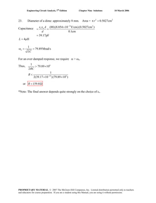
 ( )
3
9.129 10
1 2
t
C
At t = 0, v A .( )1 2 2(0) 0 12 12 VC
Taking the derivative of Eq. [1],
( )
( )
3
9.129 10 3 3
1 19.129 10 9.129 10 12C tdv t
e At A
dt
− ×
⎡ ⎤= − × + − ×⎣ ⎦
and also i i , so( )C R Li= − +
( )3
16
0
(0)1 1 12
0 0 9.129 10 12
12 10 4.565
C C
t
dv v
A
dt C R −
=
⎛ ⎞ ⎛ ⎞
= − + = − + − ×⎜ ⎟⎜ ⎟ × ⎝ ⎠⎝ ⎠
Solving,
, so we may write3
1 109.6 10 VA = − ×
.( ) ( )
3
9.129 10 3
109.6 10 12t
Cv t e t− ×
= − × +
(c) We see from plotting both the analytic result in Probe and the simulated voltage, the
two are in excellent agreement (the curves lie on top of one another).
PROPRIETARY MATERIAL. © 2007 The McGraw-Hill Companies, Inc. Limited distribution permitted only to teachers
and educators for course preparation. If you are a student using this Manual, you are using it without permission.](https://image.slidesharecdn.com/xgizwmivsiwpds00swny-signature-f172ed6d5ea07afd7eea979324352a9b3640d1cd0448b6e1a174e81551e308e0-poli-140819203045-phpapp01/85/Engineering-circuit-analysis_solutions_7ed_-hayt-564-320.jpg)
 ( )
5
3.162 10
1 2
t
Li t e At A− ×
= +
At t = 0, .( )1 2 2(0) 0 10 10 ALi A A A= + = ∴ =
Taking the derivative of Eq. [1],
( )
( )
5
3.162 10 5 5
1 13.162 10 3.162 10 10L tdi t
e At A
dt
− ×
⎡ ⎤= − × + − ×⎣ ⎦ [2]
and also
0
(0) 0L
C
t
di
L v
dt =
= = [3], so
Solving Eqs. [2] and [3],
( )( )5
1 3.162 10 10 = 3.162 10 VA = × × 6
, so we may write
.( ) ( )
5
3.162 10 6
3.162 10 10t
Li t e t− ×
= × +
(c) We see from plotting both the analytic result in Probe and the simulated voltage, the
two are in reasonable agreement (some numerical error is evident).
PROPRIETARY MATERIAL. © 2007 The McGraw-Hill Companies, Inc. Limited distribution permitted only to teachers
and educators for course preparation. If you are a student using this Manual, you are using it without permission.](https://image.slidesharecdn.com/xgizwmivsiwpds00swny-signature-f172ed6d5ea07afd7eea979324352a9b3640d1cd0448b6e1a174e81551e308e0-poli-140819203045-phpapp01/85/Engineering-circuit-analysis_solutions_7ed_-hayt-565-320.jpg)
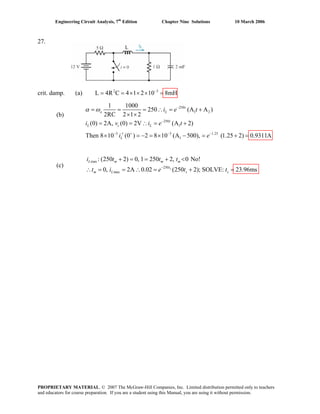
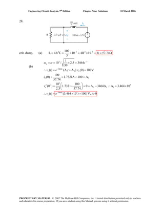
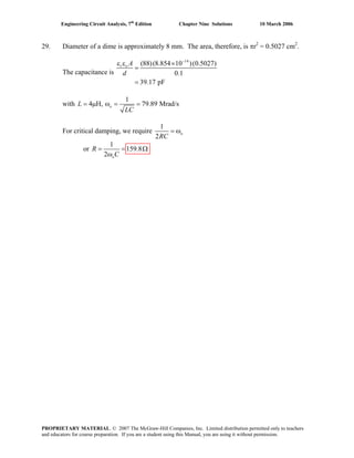
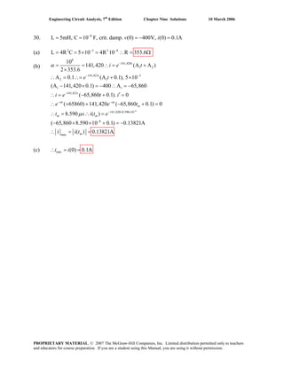
![Engineering Circuit Analysis, 7th
Edition Chapter Nine Solutions 10 March 2006
32.
2
1 2
1 4 1 4 13
1, 26, 26 1 5
2RC 2 2 LC 2
( ) ( cos5 sin5 )
o d
t
cv t e B t B t
α ω ω
−
×
= = = = = = = − =
×
∴ = +
(a) (0 ) (0) 4AL Li i+
= =
(b) (0 ) (0) 0c cv v+
= =
(c)
1
(0 ) (0 ) 0
L
L ci v+ +
′ = =
(d)
(0 )1
(0 ) [ (0 ) (0 )] 4 4 4( 4 0) 16
2
c
c L R
v
v i i
c
+
+ + + ⎡ ⎤
′ = − − = − − = − + = −⎢ ⎥
⎣ ⎦
V/s
(e)
(f)
1 1 2 2
2
( )0 1(B ) B 0, ( ) B sin5 , (0 ) B (5) 16
B 3.2, ( ) 3.2 sin5 V, 0
t
c c
t
c
e v t e t v
v t e t t
− +
−
′∴ = ∴ = = = = −
∴ = − = − >
PROPRIETARY MATERIAL. © 2007 The McGraw-Hill Companies, Inc. Limited distribution permitted only to teachers
and educators for course preparation. If you are a student using this Manual, you are using it without permission.](https://image.slidesharecdn.com/xgizwmivsiwpds00swny-signature-f172ed6d5ea07afd7eea979324352a9b3640d1cd0448b6e1a174e81551e308e0-poli-140819203045-phpapp01/85/Engineering-circuit-analysis_solutions_7ed_-hayt-572-320.jpg)
![Engineering Circuit Analysis, 7th
Edition Chapter Nine Solutions 10 March 2006
35.
(a)
9 3 9
2 8
2 2 6 6
5000 4 4
1 2
5000 4 4
2
9
1 10 1 10
5000, 1.25 10
2RC 2 20 5 LC 1.6 5
125 10 25 10 10,000
( ) (B cos10 B sin10 )
(0) 200V, (0) 10mA ( ) (200cos10 B sin10 )
1 10
(0 ) (0 ) (0)
5
−
−
−
+ +
α = = ω = = = ×
× × ×
ω = ω − α = × − × =
∴ = +
= = ∴ = +
′ = = −
o
d o
t
c
t
c L c
c
c c L
v t e t t
v i v t e t
v
v i i
c
t
9
2 4
2
5000 4 4
2
(0)
20,000
10 200
10 0 10 B 200(5000)
5 20,000
B 100V ( ) (200cos10 100sin10 ) V, 0
−
−
⎡ ⎤
⎢ ⎥
⎣ ⎦
⎛ ⎞
= − = = −⎜ ⎟
⎝ ⎠
∴ = ∴ = + >t
cv t e t t t
(b) 2
5000 4
500 6 6 5000 4
5000 9 6 5000 4
5
1
10 , C
R
[10 ( 200sin 100cos] 5000(200cos 100sin)]
[10 ( 2sin 0.5cos)] 2.5 10 sin10 /
1
(200cos 100sin) 5 10 2.5 10 sin10
20,000
−
−
− −
− −
−
′= − = +
′ = − + − +
= − − = − ×
⎡ ⎤−
∴ = + − × × ×⎢ ⎥
⎣ ⎦
=
sw L L c c
t
c
t t
t t
L
i i i v v
v e
e e t v
i e e t
e 000 4 4
5000 4 4
(0.01cos10 0.0075sin10 )A
10 (10cos10 7.5sin10 )mA, 0−
−
s
∴ = − − >
t
t
sw
t t
i e t t t
PROPRIETARY MATERIAL. © 2007 The McGraw-Hill Companies, Inc. Limited distribution permitted only to teachers
and educators for course preparation. If you are a student using this Manual, you are using it without permission.](https://image.slidesharecdn.com/xgizwmivsiwpds00swny-signature-f172ed6d5ea07afd7eea979324352a9b3640d1cd0448b6e1a174e81551e308e0-poli-140819203045-phpapp01/85/Engineering-circuit-analysis_solutions_7ed_-hayt-575-320.jpg)
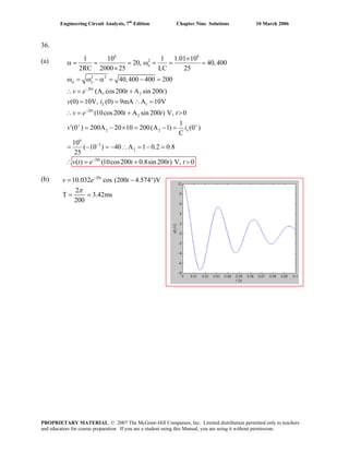
![Engineering Circuit Analysis, 7th
Edition Chapter Nine Solutions 10 March 2006
37. 6 3
1 2 6
4 4
100
1 2
100
1 2
6 6
1
1 10 1
100 , 1.01 10
2RC 2 5 LC
60
101 10 10 100; (0) 6mA
10
(0) 0 ( ) (A cos1000 A sin1000 ), 0
A 0, ( ) A sin1000
1 1
(0 ) (0 ) 10 [ (0 ) (0 )] 10
C 5000
( 6 10
−
−
−
−
+ + + +
−
α = = = ω = = ×
×
∴ω = × − = = =
= ∴ = + >
∴ = =
′ = = − − =
− ×
o
d L
t
c c
t
c
c c c
s
i
v v t e t t t
v t e t
v i i v
3
2 2
100
1 4
4 100
100
1
) 6000 1000A A 6
1
( ) 6 sin1000 V, 0 ( )
10
( ) 10 ( 6) sin1000 A
( ) 0.6 sin1000 mA, 0
−
− −
−
= − = ∴ = −
∴ = − > ∴ = −
= − −
∴ = >
t
c
t
c
t
v t e t t i t
v t e t
i t e t t
PROPRIETARY MATERIAL. © 2007 The McGraw-Hill Companies, Inc. Limited distribution permitted only to teachers
and educators for course preparation. If you are a student using this Manual, you are using it without permission.](https://image.slidesharecdn.com/xgizwmivsiwpds00swny-signature-f172ed6d5ea07afd7eea979324352a9b3640d1cd0448b6e1a174e81551e308e0-poli-140819203045-phpapp01/85/Engineering-circuit-analysis_solutions_7ed_-hayt-577-320.jpg)
![Engineering Circuit Analysis, 7th
Edition Chapter Nine Solutions 10 March 2006
38. We replace the 25-Ω resistor to obtain an underdamped response:
LC
1
and
2RC
1
0 == ωα ; we require α < ω0.
Thus, 3464
R1010
1
6
<
× −
or R > 34.64 mΩ.
For R = 34.64 Ω (1000× the minimum required value), the response is:
v(t) = e-αt
(A cos ωdt + B sin ωdt) where α = 2887 s-1
and ωd = 1914 rad/s.
iL(0+
) = iL(0-
) = 0 and vC(0+
) = vC(0-
) = (2)(25) = 50 V = A.
iL(t) =
dt
dv
dt
dv CL
LL =
= ( ) ( )[ ]tBtAettBttAe dd
t
dddd
t
ωωαωωωω αα
sincos-cossinL ++− −−
iL(0+
) = 0 = [ A-B
3
1050
d
3
αω
−
×
], so that B = 75.42 V.
Thus, v(t) = e-2887t
(50 cos 1914t + 75.42 sin 1914t) V.
From PSpice the settling time using R = 34.64 Ω is approximately 1.6 ms.
Sketch of v(t). PSpice schematic for t > 0 circuit.
PROPRIETARY MATERIAL. © 2007 The McGraw-Hill Companies, Inc. Limited distribution permitted only to teachers
and educators for course preparation. If you are a student using this Manual, you are using it without permission.](https://image.slidesharecdn.com/xgizwmivsiwpds00swny-signature-f172ed6d5ea07afd7eea979324352a9b3640d1cd0448b6e1a174e81551e308e0-poli-140819203045-phpapp01/85/Engineering-circuit-analysis_solutions_7ed_-hayt-578-320.jpg)
![Engineering Circuit Analysis, 7th
Edition Chapter Nine Solutions 10 March 2006
39.
1 1
1
1
2 1 1
/
1 1 2
/2
1
1
(0) 0; (0) 10A
(Acos Bsin ) A 0,
B sin
[ Bsin Bcos ] 0
1
tan , tan
1
T ;
2
B sin B
sin ; let
V
m m d
d
t
d d
t
d
t
d d d
d d
d m
d
m m d m
d
t t
m d m m
m
d m
m
v i
v e t t
v e t
v e t t
t t
t t t
v e t v e
v
t e
α
−α
−α
−
−α −α −απ ω
−απ ω
= =
= ω + ω ∴ =
= ω
′ = −α ω + ω ω =
ω ω
∴ ω = =
α ω α
π
= + = +
ω
= ω = −
ω ∴ = − 2
1
/
2 2
0
2
2
1
2
1
100
1 21
100, 100; ,
2RC R
1 21 100
6 6 441/ R 6R 441
LC R R
21
R 1/ 6 441 10.3781 To keep
100
0.01, chose
2
(0 )
21 0
B B 6 4R 10
10.378 10.
d
m
m
d
d
m
d
m
v
v
e n
n
v
v
v
απ ω
+
=
ω
∴ = α = α = =
π
ω = = ∴ω = − ∴ −
π
⎡ ⎤π⎛ ⎞
R 10.3780
= + = Ω⎢ ⎥⎜ ⎟
⎝ ⎠⎢ ⎥⎣ ⎦
′Ω = ω
⎛ ⎞
= − = +⎜ ⎟
⎝ ⎠
l
l
< =
∴
2
2.02351
1
2 1
B 1.380363
3780
21 21
2.02351; 6 1.380363
10.378 10.378
304.268 sin 1.380363 0.434 ,
71.2926 Computed values show
0.7126 0.01
d
t
m
s m m
v e t v t s
v v
t v v
−
⎛ ⎞
∴ =⎜ ⎟
⎝ ⎠
⎛ ⎞
α = = ω = − =⎜ ⎟
⎝ ⎠
∴
1
2.145sec;
m
= =
=
= = <
PROPRIETARY MATERIAL. © 2007 The McGraw-Hill Companies, Inc. Limited distribution permitted only to teachers
and educators for course preparation. If you are a student using this Manual, you are using it without permission.](https://image.slidesharecdn.com/xgizwmivsiwpds00swny-signature-f172ed6d5ea07afd7eea979324352a9b3640d1cd0448b6e1a174e81551e308e0-poli-140819203045-phpapp01/85/Engineering-circuit-analysis_solutions_7ed_-hayt-579-320.jpg)
![Engineering Circuit Analysis, 7th
Edition Chapter Nine Solutions 10 March 2006
40. (a) For t < 0 s, we see from the circuit that the capacitor and the resistor are shorted by
the presence of the inductor. Hence, iL(0-
) = 4 A and vC(0-
) = 0 V.
When the 4-A source turns off at t = 0 s, we are left with a parallel RLC circuit such that
α = 1/2RC = 0.4 s-1
and ω0 = 5.099 rad/s. Since α < ω0, the response will be
underdamped with ωd = 5.083 rad/s. Assume the form iL(t) = e-αt
(C cos ωdt + D sin ωdt)
for the response.
With iL(0+
) = iL(0-
) = 4 A, we find C = 4 A. To find D, we first note that
vC(t) = vL(t) = L
dt
diL
and so vC(t) = (2/13) [e-αt
(-Cωd sin ωdt + Dωd cos ωdt) - αe-αt
(C cos ωdt + D sin ωdt)]
With vC(0+
) = 0 = (2/13) (5.083D – 0.4C), we obtain D = 0.3148 A.
Thus, iL(t) = e-0.4t
(4 cos 5.083t + 0.3148 sin 5.083t) A and iL(2.5) = 1.473 A.
(b) α = 1/2RC = 4 s-1
and ω0 = 5.099 rad/s. Since α < ω0, the new response will still be
underdamped, but with ωd = 3.162 rad/s. We still may write
vC(t) = (2/13) [e-αt
(-Cωd sin ωdt + Dωd cos ωdt) - αe-αt
(C cos ωdt + D sin ωdt)]
and so with vC(0+
) = 0 = (2/13) (3.162D – 4C), we obtain D = 5.06 A.
Thus, iL(t) = e-4t
(4 cos 3.162t + 5.06 sin 3.162t) A and iL(.25) = 2.358 A.
(c)
We see from the simulation
result below that our hand
calculations are correct; the
slight disagreement is due to
numerical inaccuracy.
Changing the step ceiling
from the 10-ms value
employed to a smaller value
will improve the accuracy.
PROPRIETARY MATERIAL. © 2007 The McGraw-Hill Companies, Inc. Limited distribution permitted only to teachers
and educators for course preparation. If you are a student using this Manual, you are using it without permission.](https://image.slidesharecdn.com/xgizwmivsiwpds00swny-signature-f172ed6d5ea07afd7eea979324352a9b3640d1cd0448b6e1a174e81551e308e0-poli-140819203045-phpapp01/85/Engineering-circuit-analysis_solutions_7ed_-hayt-580-320.jpg)
![Engineering Circuit Analysis, 7th
Edition Chapter Nine Solutions 10 March 2006
41. (a,b) For t < 0 s, we see from the circuit below that the capacitor and the resistor are
shorted by the presence of the inductor. Hence, iL(0-
) = 4 A and vC(0-
) = 0 V.
When the 4-A source turns off at t = 0 s, we are left with a parallel RLC circuit such that
α = 1/2RC = 1 s-1
and ω0 = 5.099 rad/s. Since α < ω0, the response will be underdamped
with ωd = 5 rad/s. Assume the form iL(t) = e-αt
(C cos ωdt + D sin ωdt) for the response.
With iL(0+
) = iL(0-
) = 4 A, we find C = 4 A. To find D, we first note that
vC(t) = vL(t) = L
dt
diL
and so vC(t) = (2/13) [e-αt
(-Cωd sin ωdt + Dωd cos ωdt) - αe-αt
(C cos ωdt + D sin ωdt)]
With vC(0+
) = 0 = (2/13) (5D – 4), we obtain D = 0.8 A.
Thus, iL(t) = e-t
(4 cos 5t + 0.8 sin 5t) A
(c) Using the cursor tool, the settling
time is approximately 4.65 s.
We see that the simulation
result confirms our hand
analysis; there is only a
slight difference due to
numerical error between
the simulation result and
our exact expression.
PROPRIETARY MATERIAL. © 2007 The McGraw-Hill Companies, Inc. Limited distribution permitted only to teachers
and educators for course preparation. If you are a student using this Manual, you are using it without permission.](https://image.slidesharecdn.com/xgizwmivsiwpds00swny-signature-f172ed6d5ea07afd7eea979324352a9b3640d1cd0448b6e1a174e81551e308e0-poli-140819203045-phpapp01/85/Engineering-circuit-analysis_solutions_7ed_-hayt-581-320.jpg)
![Engineering Circuit Analysis, 7th
Edition Chapter Nine Solutions 10 March 2006
42.
2 2
20
1 2 1
20
2
20
2 2
R 80
(0) 50 80 2 210V, (0) 0, 20
2L 4
100
500: 500 20 10
2
( ) (A cos10 A sin10 ) A 210V
1
( ) (210cos10 A sin10 ); (0 ) (0 ) 0
C
0 10A 20(210), A 420 ( ) (210cos10
c L
o d
t
c
t
c c c
t
c
v i
v t e t t
v t e t t v i
v t e t
α
ω ω
−
− + +
−
= + × = = = = =
= = = − =
∴ = + ∴ =
′∴ = + = =
∴ = − = ∴ = +
0.8
20
1 2
2 2
20
20
420sin10 )
(40ms) (210cos0.4 420sin 0.4) 160.40V
Also, (B cos10 B sin10 ),
1 1 1
(0 ) (0 ) [0 (0 )] 210
L 2 2
(0 ) 105 10B B 10.5
( ) 10.5 sin10 A, 0
( ) 80 840 sin
c
t
L
L L c
L
t
L
t
R L
t
v e
i e t t
i v v
i
i t e t t
v t i e
−
−
+ + +
+
−
−
∴ = + =
= +
= = − = ×
′∴ = − = ∴ =
∴ = − >
∴ = =
0.8
20
20
0.8
10 V
(40ms) 840 sin 0.4 146.98V
( ) ( ) ( ) ( )
(40ms) 160.40 146.98 13.420V
[check: ( 210cos 420sin 840sin)
( 210cos10 420sin10 )V, 0
(40ms) ( 210cos 420sin 840
R
L c c R L
t
L
t
L
t
v e
v t v t v t v t v
v e
e t t t
v e
−
−
−
−
∴ = − = −
= − − − ∴
= − + = −
= − − +
= − + >
∴ = − − + 20
0.8
sin)
( 210cos10 420sin10 )V, 0
V (40ms)
(420sin 0.4 210cos0.4) 13.420VChecks]
t
L
e
t t t
e
−
−
=
− + >
∴ =
− = −
PROPRIETARY MATERIAL. © 2007 The McGraw-Hill Companies, Inc. Limited distribution permitted only to teachers
and educators for course preparation. If you are a student using this Manual, you are using it without permission.](https://image.slidesharecdn.com/xgizwmivsiwpds00swny-signature-f172ed6d5ea07afd7eea979324352a9b3640d1cd0448b6e1a174e81551e308e0-poli-140819203045-phpapp01/85/Engineering-circuit-analysis_solutions_7ed_-hayt-582-320.jpg)
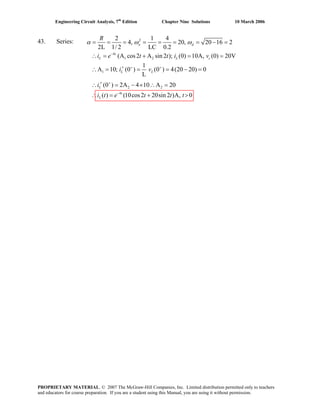
![Engineering Circuit Analysis, 7th
Edition Chapter Nine Solutions 10 March 2006
44. (a)
2
2 2 2
2
4 6 4
10000
1 2
10000
2 1
6
1
R 1 1
crit. damp; L R C
4L LC 4
1 200
L 4 10 0.01H, 10
4 0.02
( ) (A A ); (0) 10V, (0) 0.15A
1
A 10, ( ) (A 0); (0 )
C
(0) 10 ( 0.15) 150,000
Now, (0 ) A
−
−
− +
+
= = = ∴ =
∴ = × × = = = =
∴ = + = − = −
′∴ = − = − = −
= − − =
′ =
o
o
t
c c L
t
c c
L
c
v t e t v i
v t e t v
i
v
α ω
α ω
5
1
10,000
10 150,000 A 50,000
( ) (50,000 10) V, 0−
+ = ∴ =
= − >t
cv t e t t∴
(b) 10,000
3 3
max
( ) [50,000 10,000(50,000 10)]
15
5 50,000 10 0.3ms
50,000
( ) (15 10) 5 0.2489V
(0) 10V 10V
t
c
m m
c m
c c
e t
t t
v t e e
v v
−
− −
′ = − − =∴
= − ∴ = =
v t
∴
(c) ,max 0.2489Vcv =
= − = =
= − ∴ =
PROPRIETARY MATERIAL. © 2007 The McGraw-Hill Companies, Inc. Limited distribution permitted only to teachers
and educators for course preparation. If you are a student using this Manual, you are using it without permission.](https://image.slidesharecdn.com/xgizwmivsiwpds00swny-signature-f172ed6d5ea07afd7eea979324352a9b3640d1cd0448b6e1a174e81551e308e0-poli-140819203045-phpapp01/85/Engineering-circuit-analysis_solutions_7ed_-hayt-584-320.jpg)
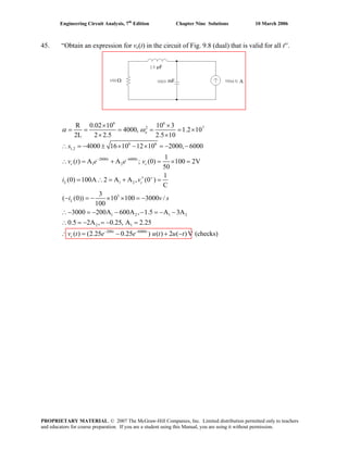
![Engineering Circuit Analysis, 7th
Edition Chapter Nine Solutions 10 March 2006
46. (a) 2 2
1 2
1 2
1 2
2
R 2 1
1, 5, 2
2L 2 LC
(B cos2 B sin 2 ), (0) 0, (0) 10V
B 0, B sin 2
1
(0) (0 ) (0 ) V (0 ) 0 10 2B
1
B 5 5 sin 2 A, 0
o d o
t
L L
t
L
L R c
t
L
i e t t i v
i e t
i v v
i e t t
2
c
ω ω α
−
−
+ + +
−
= = = = = = − =α ω
∴ = + = =
∴ = =
= = − = − =
∴ = ∴ = − >
(b)
1 1
2 2
2 max
max
5[ (2cos2 sin 2 )] 0
2cos2 sin 2 ,tan 2 2
0.5536 , ( ) 2.571A
2 2 0.5536 , 2.124,
( ) 0.5345 2.571A
and 0.5345A
−
′ = − − =
∴ = =
∴ = = −
= × + =
= ∴ =
=
t
L
L
L L
L
t t
t t t
t s i t
t t
i t i
i
π
i e
PROPRIETARY MATERIAL. © 2007 The McGraw-Hill Companies, Inc. Limited distribution permitted only to teachers
and educators for course preparation. If you are a student using this Manual, you are using it without permission.](https://image.slidesharecdn.com/xgizwmivsiwpds00swny-signature-f172ed6d5ea07afd7eea979324352a9b3640d1cd0448b6e1a174e81551e308e0-poli-140819203045-phpapp01/85/Engineering-circuit-analysis_solutions_7ed_-hayt-586-320.jpg)
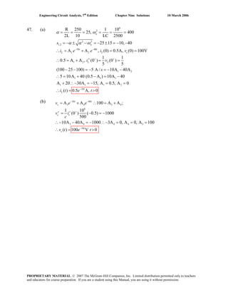
![Engineering Circuit Analysis, 7th
Edition Chapter Nine Solutions 10 March 2006
48. Considering the circuit as it exists for t < 0, we conclude that vC(0-
) = 0 and iL(0-
) = 9/4 =
2.25 A. For t > 0, we are left with a parallel RLC circuit having α = 1/2RC = 0.25 s-1
and
ωo = 1/ LC = 0.3333 rad/s. Thus, we expect an underdamped response with ωd =
0.2205 rad/s:
iL(t) = e-αt
(A cos ωdt + B sin ωdt)
iL(0+
) = iL(0-
) = 2.25 = A
so iL(t) = e–0.25t
(2.25 cos 0.2205t + B sin 0.2205t)
In order to determine B, we must invoke the remaining boundary condition. Noting that
vC(t) = vL(t) = L
dt
diL
= (9)(-0.25)e-0.25t
(2.25 cos 0.2205t + B sin 0.2205t)
+ (9) e-0.25t
[-2.25(0.2205) sin 0.2205t + 0.2205B cos 0.2205t]
vC(0+
) = vC(0-
) = 0 = (9)(-0.25)(2.25) + (9)(0.2205B)
so B = 2.551 and
iL(t) = e-0.25t
[2.25 cos 0.2205t + 2.551 sin 0.2205t] A
Thus, iL(2) = 1.895 A
This answer is borne out by PSpice simulation:
PROPRIETARY MATERIAL. © 2007 The McGraw-Hill Companies, Inc. Limited distribution permitted only to teachers
and educators for course preparation. If you are a student using this Manual, you are using it without permission.](https://image.slidesharecdn.com/xgizwmivsiwpds00swny-signature-f172ed6d5ea07afd7eea979324352a9b3640d1cd0448b6e1a174e81551e308e0-poli-140819203045-phpapp01/85/Engineering-circuit-analysis_solutions_7ed_-hayt-588-320.jpg)
![Engineering Circuit Analysis, 7th
Edition Chapter Nine Solutions 10 March 2006
49. We are presented with a series RLC circuit having
α = R/2L = 4700 s-1
and ωo = 1/ LC = 447.2 rad/s; therefore we expect an
overdamped response with s1 = -21.32 s-1
and s2 = -9379 s-1
.
From the circuit as it exists for t < 0, it is evident that iL(0-
) = 0 and vC(0-
) = 4.7 kV
Thus, vL(t) = A e–21.32t
+ B e-9379t
[1]
With iL(0+
) = iL(0-
) = 0 and iR(0+
) = 0 we conclude that vR(0+
) = 0; this leads to vL(0+
) =
-vC(0-
) = -4.7 kV and hence A + B = -4700 [2]
Since vL = L
dt
di
, we may integrate Eq. [1] to find an expression for the inductor current:
iL(t) = ⎥
⎦
⎤
⎢
⎣
⎡ −− tt
ee 937932.21
9379
B
-
21.32
A
-
L
1
At t = 0+
, iL = 0 so we have 0
9379
B
-
21.32
A
-
10500
1
3-
=⎥
⎦
⎤
⎢
⎣
⎡
×
[3]
Simultaneous solution of Eqs. [2] and [3] yields A = 10.71 and B = -4711. Thus,
vL(t) = 10.71e-21.32t
- 4711 e-9379t
V, t > 0
and the peak inductor voltage magnitude is 4700 V.
PROPRIETARY MATERIAL. © 2007 The McGraw-Hill Companies, Inc. Limited distribution permitted only to teachers
and educators for course preparation. If you are a student using this Manual, you are using it without permission.](https://image.slidesharecdn.com/xgizwmivsiwpds00swny-signature-f172ed6d5ea07afd7eea979324352a9b3640d1cd0448b6e1a174e81551e308e0-poli-140819203045-phpapp01/85/Engineering-circuit-analysis_solutions_7ed_-hayt-589-320.jpg)
![Engineering Circuit Analysis, 7th
Edition Chapter Nine Solutions 10 March 2006
50. With the 144 mJ originally stored via a 12-V battery, we know that the capacitor has a
value of 2 mF. The initial inductor current is zero, and the initial capacitor voltage is 12
V. We begin by seeking a (painful) current response of the form
ibear = Aes1
t
+ Bes2
t
Using our first initial condition, ibear(0+
) = iL(0+
) = iL(0-
) = 0 = A + B
di/dt = As1 es1
t
+ Bs2 es2
t
vL = Ldi/dt = ALs1 es1
t
+ BLs2 es2
t
vL(0+
) = ALs1 + BLs2 = vC(0+
) = vC(0-
) = 12
What else is known? We know that the bear stops reacting at t = 18 μs, meaning that the
current flowing through its fur coat has dropped just below 100 mA by then (not a long
shock).
Thus, A exp[(18×10-6
)s1] + B exp[(18×10-6
)s2] = 100×10-3
Iterating, we find that Rbear = 119.9775 Ω.
This corresponds to A = 100 mA, B = -100 mA, s1 = -4.167 s-1
and s2 = -24×106
s-1
PROPRIETARY MATERIAL. © 2007 The McGraw-Hill Companies, Inc. Limited distribution permitted only to teachers
and educators for course preparation. If you are a student using this Manual, you are using it without permission.](https://image.slidesharecdn.com/xgizwmivsiwpds00swny-signature-f172ed6d5ea07afd7eea979324352a9b3640d1cd0448b6e1a174e81551e308e0-poli-140819203045-phpapp01/85/Engineering-circuit-analysis_solutions_7ed_-hayt-590-320.jpg)
![Engineering Circuit Analysis, 7th
Edition Chapter Nine Solutions 10 March 2006
51. Considering the circuit at t < 0, we note that iL(0-
) = 9/4 = 2.25 A and vC(0-
) = 0.
For a critically damped circuit, we require α = ωo, or
LC
1
RC2
1
= , which, with
L = 9 H and C = 1 F, leads to the requirement that R = 1.5 Ω (so α = 0.3333 s-1
).
The inductor energy is given by wL = ½ L [iL(t)]2
, so we seek an expression for iL(t):
iL(t) = e-αt
(At + B)
Noting that iL(0+
) = iL(0-
) = 2.25, we see that B = 2.25 and hence
iL(t) = e-0.3333t
(At + 2.25)
Invoking the remaining initial condition requires consideration of the voltage across the
capacitor, which is equal in this case to the inductor voltage, given by:
vC(t) = vL(t) =
dt
diL
L = 9(-0.3333) e-0.3333t
(At + 2.25) + 9A e-0.3333t
vC(0+
) = vC(0-
) = 0 = 9(-0.333)(2.25) + 9A so A = 0.7499 amperes and
iL(t) = e-0.3333t
(0.7499t + 2.25) A
Thus, iL(100 ms) = 2.249 A and so wL(100 ms) = 22.76 J
PROPRIETARY MATERIAL. © 2007 The McGraw-Hill Companies, Inc. Limited distribution permitted only to teachers
and educators for course preparation. If you are a student using this Manual, you are using it without permission.](https://image.slidesharecdn.com/xgizwmivsiwpds00swny-signature-f172ed6d5ea07afd7eea979324352a9b3640d1cd0448b6e1a174e81551e308e0-poli-140819203045-phpapp01/85/Engineering-circuit-analysis_solutions_7ed_-hayt-591-320.jpg)
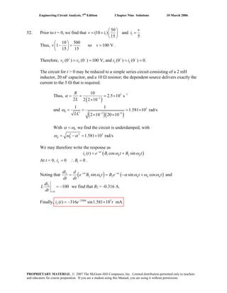
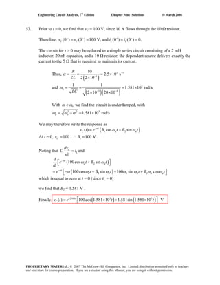
![Engineering Circuit Analysis, 7th
Edition Chapter Nine Solutions 10 March 2006
54. Prior to t = 0, i1 = 10/4 = 2.5 A, v = 7.5 V, and vg = –5 V.
Thus, vC(0+
) = vC(0–
) = 7.5 + 5 = 12.5 V and iL = 0
After t = 0 we are left with a series RLC circuit where 1
4
Li
i = − . We may replace the
dependent current source with a 0.5 Ω resistor. Thus, we have a series RLC circuit with R
= 1.25 Ω, C = 1 F, and L = 3 H.
Thus, 11.25
0.208 s
2 6
R
L
α −
= = =
and 0
1 1
577 mrad/s
3LC
ω = = =
With 0α ω< we find the circuit is underdamped, so that
2 2
0 538 mrad/sdω ω α= − =
We may therefore write the response as
( )1 2( ) cos sint
L di t e B t B tα
dω ω−
= +
At t = 0, i B .10 0 AL = ∴ =
Noting that
0
(0)L
C
t
di
L v and
dt =
= −
( ) [ ]2 2
( ) 12.5
sin sin cos ( 0)
3
t t CL
d d d d
v tdi d
e B t B e t t t
dt dt L
α α
ω α ω ω ω− − −
⎡ ⎤= = − + = =⎣ ⎦ =
,
we find that BB
2 = –7.738 V.
Finally, i t for t > 0 and 2.5 A, t < 00.208
( ) 1.935 sin 0.538 At
L e t−
=
PROPRIETARY MATERIAL. © 2007 The McGraw-Hill Companies, Inc. Limited distribution permitted only to teachers
and educators for course preparation. If you are a student using this Manual, you are using it without permission.](https://image.slidesharecdn.com/xgizwmivsiwpds00swny-signature-f172ed6d5ea07afd7eea979324352a9b3640d1cd0448b6e1a174e81551e308e0-poli-140819203045-phpapp01/85/Engineering-circuit-analysis_solutions_7ed_-hayt-594-320.jpg)
![Engineering Circuit Analysis, 7th
Edition Chapter Nine Solutions 10 March 2006
55. Prior to t = 0, i1 = 10/4 = 2.5 A, v = 7.5 V, and vg = –5 V.
Thus, vC(0+
) = vC(0–
) = 12.5 V and iL = 0
After t = 0 we are left with a series RLC circuit where 1
4
Li
i = − . We may replace the
dependent current source with a 0.5 Ω resistor. Thus, we have a series RLC circuit with R
= 1.25 Ω, C = 1 mF, and L = 3 H.
Thus, 11.25
0.208 s
2 6
R
L
α −
= = =
and
( )
0
3
1 1
18.26 rad/s
3 10LC
ω
−
= = =
×
With 0α ω< we find the circuit is underdamped, so that
2 2
0 18.26 rad/sdω ω α= − =
We may therefore write the response as
( )1 2( ) cos sint
C dv t e B t B tα
dω ω−
= +
At t = 0, v B .112.5 12.5 VC = ∴ =
Noting that
( )
[ ] [
1 2
2 2
cos sin
12.5cos sin 12.5 sin cos
tC
d d
t t
d d d d d
dv d
e B t B t
dt dt
e t B t e t B
α
α α
ω ω
]dtα ω ω ω ω ω
−
− −
⎡ ⎤= +⎣ ⎦
= − + + − + ω
and this expression is equal to 0 at t = 0,
we find that BB
2 = 0.143 V.
Finally, [ ]0.208
( ) 12.5cos18.26 0.143sin18.26 Vt
Cv t for t > 0 and 12.5 V, t < 0e t t−
= +
PROPRIETARY MATERIAL. © 2007 The McGraw-Hill Companies, Inc. Limited distribution permitted only to teachers
and educators for course preparation. If you are a student using this Manual, you are using it without permission.](https://image.slidesharecdn.com/xgizwmivsiwpds00swny-signature-f172ed6d5ea07afd7eea979324352a9b3640d1cd0448b6e1a174e81551e308e0-poli-140819203045-phpapp01/85/Engineering-circuit-analysis_solutions_7ed_-hayt-595-320.jpg)
![Engineering Circuit Analysis, 7th
Edition Chapter Nine Solutions 10 March 2006
56. (a)
6
2
500
1 2 2 2
1
5000 500
1
R 100
Series, driven: 500,
2L 0.2
1 10 10
250,000
LC 40
Crit. damp ( ) 3(1 2) 3,
(0) 3, (0) 300V
3 (A A ) 3 3 A , A
1
(0 ) A 300 [ (0) (0 )] 0
L
A 3000 ( ) 3
o
L
L c
t
L
L c R
t
L
i f
6Ai e t
i v v
e i t e
α
ω
−
+ +
− −
= = =
×
= = =
∴
i v
= − = −
= =
∴ = − + + ∴ = − + =
= − = − =
∴ = ∴ = − +
500
(3000 6), 0
( ) 3 ( ) [ 3 (3000 6)] ( )A
t
t
L
t t
i t u t e t u t−
+ >
(b) 500
(3000 6) 3; by SOLVE, 3.357msot
o oe t t−
+ = =
= − + − + +∴
PROPRIETARY MATERIAL. © 2007 The McGraw-Hill Companies, Inc. Limited distribution permitted only to teachers
and educators for course preparation. If you are a student using this Manual, you are using it without permission.](https://image.slidesharecdn.com/xgizwmivsiwpds00swny-signature-f172ed6d5ea07afd7eea979324352a9b3640d1cd0448b6e1a174e81551e308e0-poli-140819203045-phpapp01/85/Engineering-circuit-analysis_solutions_7ed_-hayt-596-320.jpg)
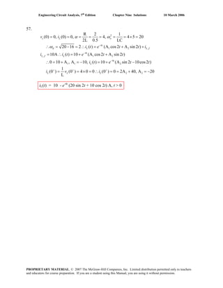
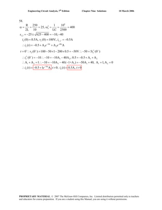
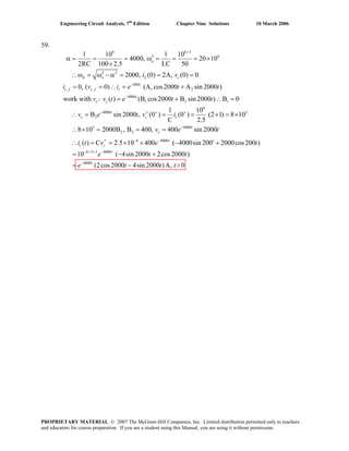
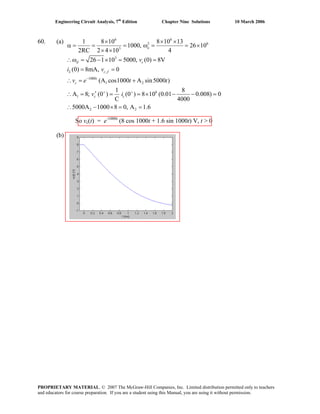
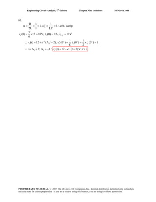
![Engineering Circuit Analysis, 7th
Edition Chapter Nine Solutions 10 March 2006
62. (a)
(b) v u 500 1500
, 3 4
6
3 4
6
3 4
3 4 4 4 3
500 1500
10 ( )V, 10, 10 A A ,
(0) 0, (0) 0 A A 10V, (0 ) 2 10
[ (0) (0 )] 2 10 (0 0) 0 500A 1500A
A 3A 0, add: 2A 10, A 5 A 15
( ) 10 15 5 V, 0
( )
t t
s c f c
c L c
L R
t t
c
R
t v v e e
v i v
i i
v t e e t
i t
− −
+
+
− −
= = = + +
′= = ∴ + = − = ×
− = × − = = − −
∴− − = − = − = ∴ = −
∴ = − + >
500 1500
10 15 5 mA, 0t t
e e t−
= − + >∴
6
6
2 6
1,2
500 1500
1 2
6 6
1 2
1 2
1 10
10 ( ) V : 1000
2RC 2000 0.5
1 2 10 3
0.75 10 500, 1500
LC 8
A A , (0) 10V, (0) 10mA
A 10, (0 ) 2 10 [ (0) (0 )] 2 10
10
0.01 0 500A 1500A 0,
1000
A
s
o
t t
c o L
c L R
v u t
s
v e e v i
A v i i
− −
+ +
= − α = = =
×
× ×
ω = = = × ∴ = − −
∴ = + = =
′∴ + = = × − = ×
⎛ ⎞
− = ∴− − =⎜ ⎟
⎝ ⎠
− 1 2 2 2 1
500 1500
500 1500
3A 0; add: 2A 10, A 5, A 15
( ) 15 5 V 0
( ) 15 5 mA, 0
t t
c
t t
R
v t e e t
i t e e t
− −
− −
− = − = = − =
∴ = − >
∴ = − >
PROPRIETARY MATERIAL. © 2007 The McGraw-Hill Companies, Inc. Limited distribution permitted only to teachers
and educators for course preparation. If you are a student using this Manual, you are using it without permission.](https://image.slidesharecdn.com/xgizwmivsiwpds00swny-signature-f172ed6d5ea07afd7eea979324352a9b3640d1cd0448b6e1a174e81551e308e0-poli-140819203045-phpapp01/85/Engineering-circuit-analysis_solutions_7ed_-hayt-602-320.jpg)
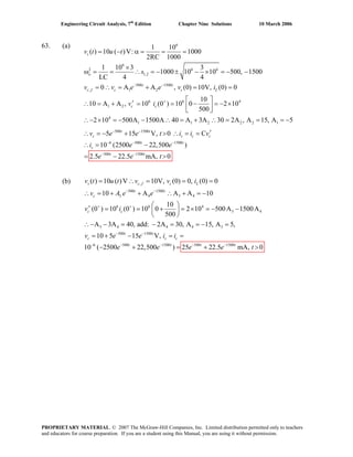
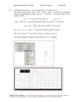
![Engineering Circuit Analysis, 7th
Edition Chapter Nine Solutions 10 March 2006
65. (a) vS(0-
) = vC(0-
) = 2(15) = 30 V
(b) iL(0+
) = iL(0-
) = 15 A
Thus, iC(0+
) = 22 – 15 = 7 A and vS(0+
) = 3(7) + vC(0+
) = 51 V
(c) As t → ∞, the current through the inductor approaches 22 A, so vS(t→ ∞,) = 44 A.
(d) We are presented with a series RLC circuit having α = 5/2 = 2.5 s-1
and ωo = 3.536
rad/s. The natural response will therefore be underdamped with ωd = 2.501 rad/s.
iL(t) = 22 + e-αt
(A cos ωdt + B sin ωdt)
iL(0+
) = iL(0-
) = 15 = 22 + A so A = -7 amperes
Thus, iL(t) = 22 + e-2.5t
(-7 cos 2.501t + B sin 2.501t)
vS(t) = 2 iL(t) +
dt
di
i
dt
di L
L
L
2L += = 44 + 2e-2.5t
(-7cos 2.501t + Bsin 2.501t)
– 2.5e-2.5t
(-7cos 2.501t + Bsin 2.501t) + e-2.5t
[7(2.501) sin 2.501t + 2.501B cos 2.501t)]
vS(t) = 51 = 44 + 2(-7) – 2.5(-7) + 2.501B so B = 1.399 amperes and hence
vS(t) = 44 + 2e-2.5t
(-7cos 2.501t + 1.399sin 2.501t)
-2.5e-2.5t
(-7cos 2.501t + 1.399sin 2.501t) + e-2.5t
[17.51sin 2.501t + 3.499cos 2.501t)]
and vS(t) at t = 3.4 s = 44.002 V. This is borne out by PSpice simulation:
PROPRIETARY MATERIAL. © 2007 The McGraw-Hill Companies, Inc. Limited distribution permitted only to teachers
and educators for course preparation. If you are a student using this Manual, you are using it without permission.](https://image.slidesharecdn.com/xgizwmivsiwpds00swny-signature-f172ed6d5ea07afd7eea979324352a9b3640d1cd0448b6e1a174e81551e308e0-poli-140819203045-phpapp01/85/Engineering-circuit-analysis_solutions_7ed_-hayt-605-320.jpg)
![Engineering Circuit Analysis, 7th
Edition Chapter Nine Solutions 10 March 2006
66. For t < 0, we have 15 A dc flowing, so that iL = 15 A, vC = 30 V, v3Ω = 0 and vS = 30 V.
This is a series RLC circuit with α = R/2L = 2.5 s-1
and ω0 = 3.536 rad/s. We therefore
expect an underdamped response with ωd = 2.501 rad/s.
0 < t < 1 vC(t) = e-αt
(A cos ωdt + B sin ωdt)
vC(0+
) = vC(0-
) = 30 = A so we may write vC(t) = e-2.5t
(30 cos 2.501t + B sin 2.501t)
C
=
dt
dv
-2.5e-2.5t
(30 cos 2.501t + B sin 2.501t)
+ e-2.5t
[-30(2.501)sin 2.501t + 2.501B cos 2.501t]
iC(0+
) =
0
C
+
=tdt
dv
C = 80×10-3
[-2.5(30) + 2.501B] = -iL(0+
) = -iL(0-
) = -15 so B = -44.98 V
Thus, vC(t) = e-2.5t
(30 cos 2.501t – 44.98 sin 2.501t) and
iC(t) = e-2.5t
(-15 cos 2.501t + 2.994 sin 2.501t).
Hence, vS(t) = 3 iC(t) + vC(t) = e-2.5t
(-15 cos 2.501t – 36 sin 2.501t)
Prior to switching, vC(t = 1) = -4.181 V and iL(t = 1) = -iC(t = 1) = -1.134 A.
t > 2: Define t' = t – 1 for notational simplicity. Then, with the fact that vC(∞) = 6 V,
our response will now be vC(t') = e-αt'
(A' cos ωdt' + B' sin ωdt') + 6.
With vC(0+
) = A' + 6 = -4.181, we find that A' = -10.18 V.
iC(0+
) =
0
C
+
=′
′ t
td
dv
C = (80×10-3
)[(-2.5)(-10.18) + 2.501B')] = 3 – iL(0+
) so B' = 10.48 V
Thus, vC(t') = e-2.5t
(-10.18 cos 2.501t' + 10.48 sin 2.501t') and
iC(t') = e-2.5t
(4.133 cos 2.501t' – 0.05919 sin 2.501t').
Hence, vS(t') = 3 iC(t') + vC(t') = e-2.5t
(2.219 cos 2.501t' + 10.36 sin 2.501t')
We see that our hand
calculations are supported by
the PSpice simulation.
PROPRIETARY MATERIAL. © 2007 The McGraw-Hill Companies, Inc. Limited distribution permitted only to teachers
and educators for course preparation. If you are a student using this Manual, you are using it without permission.](https://image.slidesharecdn.com/xgizwmivsiwpds00swny-signature-f172ed6d5ea07afd7eea979324352a9b3640d1cd0448b6e1a174e81551e308e0-poli-140819203045-phpapp01/85/Engineering-circuit-analysis_solutions_7ed_-hayt-606-320.jpg)
![Engineering Circuit Analysis, 7th
Edition Chapter Nine Solutions 10 March 2006
67. It’s probably easiest to begin by sketching the waveform vx:
(a) The source current ( = iL(t) ) = 0 at t = 0-
.
(b) iL(t) = 0 at t = 0+
(c) We are faced with a series RLC circuit having α = R/2L = 2000 rad/s and ω0 = 2828
rad/s. Thus, an underdamped response is expected with ωd = 1999 rad/s.
The general form of the expected response is iL(t) = e-αt
(A cos ωdt + B sin ωdt)
iL(0+
) = iL(0-
) = 0 = A so A = 0. This leaves iL(t) = B e-2000t
sin 1999t
vL(t) = L
dt
diL
= B[(5×10⁻³
)(-2000 e-2000t
sin 1999t + 1999 e-2000t
cos 1999t)]
vL(0+
) = vx(0+
) – vC(0+
) – 20 iL(0+
) = B (5×10⁻³
)(1999) so B = 7.504 A.
Thus, iL(t) = 7.504 e-2000t
sin 1999t and iL(1 ms) = 0.9239 A.
(d) Define t' = t – 1 ms for notational convenience. With no source present, we expect a
new response but with the same general form:
iL(t') = e-2000t'
(A' cos 1999t' + B' sin 1999t')
vL(t) = L
dt
diL
, and this enables us to calculate that vL(t = 1 ms) = -13.54 V. Prior to the
pulse returning to zero volts, -75 + vL + vC + 20 iL = 0 so vC(t' = 0) = 69.97 V.
iL(t' = 0) = A' = 0.9239 and –vx + vL + vC + 20 iL = 0 so that B' = -7.925.
Thus, iL(t') = e-2000 t' (0.9239 cos 1999t' – 7.925 sin 1999t') and
hence iL(t = 2 ms) = iL(t' = 1 ms) = -1.028 A.
1 2 3 4
t (s)
vx (V)
75
PROPRIETARY MATERIAL. © 2007 The McGraw-Hill Companies, Inc. Limited distribution permitted only to teachers
and educators for course preparation. If you are a student using this Manual, you are using it without permission.](https://image.slidesharecdn.com/xgizwmivsiwpds00swny-signature-f172ed6d5ea07afd7eea979324352a9b3640d1cd0448b6e1a174e81551e308e0-poli-140819203045-phpapp01/85/Engineering-circuit-analysis_solutions_7ed_-hayt-607-320.jpg)
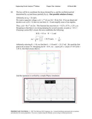
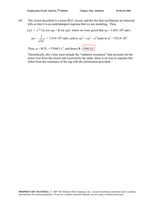
![Engineering Circuit Analysis, 7th
Edition Chapter Nine Solutions 10 March 2006
70. For t < 0, iL(0-
) = 3 A and vC(0-
) = 25(3) = 75 V. This is a series RLC circuit with α =
R/2L = 5000 s-1
and ω0 = 4000 rad/s. We therefore expect an overdamped response with
s1 = -2000 s-1
and s2 = -8000 s-1
. The final value of vC = -50 V.
For t > 0, vC(t) = A e-2000t
+ B e-8000t
- 50
vC(0+
) = vC(0-
) = 75 = A + B – 50
so A + B = 125 [1]
dt
dvC
= -2000 Ae-2000t
– 8000 Be-8000t
iC(0+
) =
+
=0
C
tdt
dv
C = 3 – 5 – iL(0-
) = -5 = -25×10-6
(2000A + 8000B)
Thus, 2000A + 8000B = 5/25×10-6
[2]
Solving Eqs. [1] and [2], we find that A = 133.3 V and B = -8.333 V. Thus,
vC(t) = 133.3 e-2000t
– 8.333 e-8000t
– 50
and vC(1 ms) = -31.96 V. This is confirmed by the PSpice simulation shown below.
PROPRIETARY MATERIAL. © 2007 The McGraw-Hill Companies, Inc. Limited distribution permitted only to teachers
and educators for course preparation. If you are a student using this Manual, you are using it without permission.](https://image.slidesharecdn.com/xgizwmivsiwpds00swny-signature-f172ed6d5ea07afd7eea979324352a9b3640d1cd0448b6e1a174e81551e308e0-poli-140819203045-phpapp01/85/Engineering-circuit-analysis_solutions_7ed_-hayt-610-320.jpg)
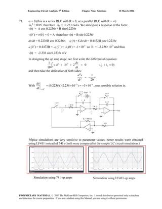
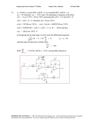
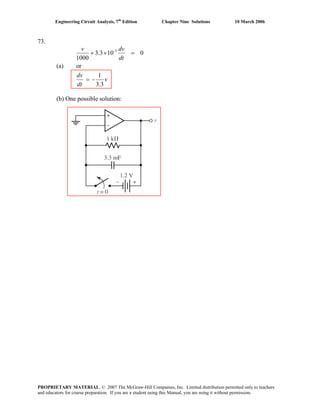
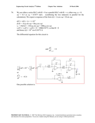
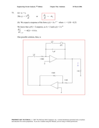
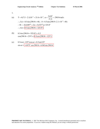
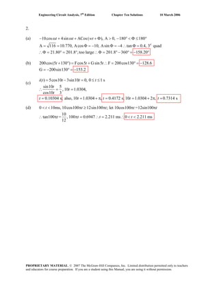

![Engineering Circuit Analysis, 7th
Edition Chapter Ten Solutions 10 March 2006
4. i t = ω( ) Acos( ), and
L( / ) R V cos
L[ Asin ( )] RAcos( ) V cos
LAsin cos LAcos sin RAcos cos RAsin sin
V cos
LAcos RAsin
and sin RAcos V
L
, tan
m
m
m
m
t
di dt i t
t t t
t t t t
t
LA
Thus
− θ
+ = ω
∴ −ω ω −θ + ω − θ = ω
−ω ω θ + ω ω θ+ ω θ+ ω θ
= ω
∴ ω θ = θ
ω θ+ θ =
ω
θ =
( ) ( )
2 2 2 2 2 2
2 2 2
2 2 2 2 2 2
2 2 2
2 2 2
L R
and LA RA V
R L R L
L R
so that A V
R L R L
V
, R L A V and therefore we may write A
R L
m
m
m
m
R
Thus
ω
ω + =
+ ω + ω
⎛ ⎞ω
+ =⎜ ⎟
+ ω + ω⎝ ⎠
+ ω = =
+ ω
*
*
PROPRIETARY MATERIAL. © 2007 The McGraw-Hill Companies, Inc. Limited distribution permitted only to teachers
and educators for course preparation. If you are a student using this Manual, you are using it without permission.](https://image.slidesharecdn.com/xgizwmivsiwpds00swny-signature-f172ed6d5ea07afd7eea979324352a9b3640d1cd0448b6e1a174e81551e308e0-poli-140819203045-phpapp01/85/Engineering-circuit-analysis_solutions_7ed_-hayt-619-320.jpg)
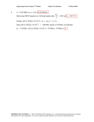
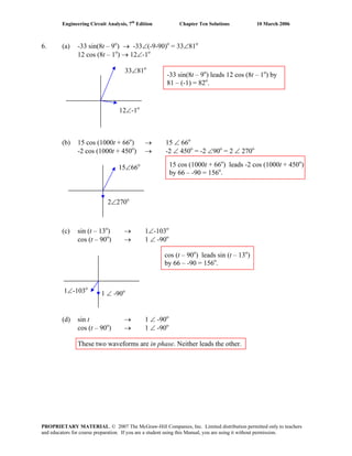
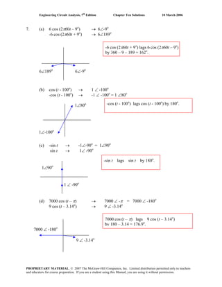
![Engineering Circuit Analysis, 7th
Edition Chapter Ten Solutions 10 March 2006
8. v(t) = V1 cos ωt - V2 sin ωt [1]
We assume this can be written as a single cosine such that
v(t) = Vm cos (ωt + φ) = Vm cos ωt cos φ - Vm sin ωt sin φ [2]
Equating terms on the right hand sides of Eqs. [1] and [2],
V1 cos ωt – V2 sin ωt = (Vm cos φ) cos ωt – (Vm sin φ) sin ωt
yields
V1 = Vm cos φ and V2 = Vm sin φ
Dividing, we find that φ
φ
φ
tan
cosV
sinV
V
V
m
m
1
2
== and φ = tan-1
(V2/ V1)
Next, we see from the above sketch that we may write Vm = V1/ cos φ or
2
2
2
11
1
m
VVV
V
V
+
= = 2
2
2
1 VV +
φ
V2
V1
2
2
2
1 VV +
Thus, we can write v(t) = Vm cos (ωt + φ) = 2
2
2
1 VV + cos [ ωt + tan-1
(V2/ V1)].
PROPRIETARY MATERIAL. © 2007 The McGraw-Hill Companies, Inc. Limited distribution permitted only to teachers
and educators for course preparation. If you are a student using this Manual, you are using it without permission.](https://image.slidesharecdn.com/xgizwmivsiwpds00swny-signature-f172ed6d5ea07afd7eea979324352a9b3640d1cd0448b6e1a174e81551e308e0-poli-140819203045-phpapp01/85/Engineering-circuit-analysis_solutions_7ed_-hayt-623-320.jpg)
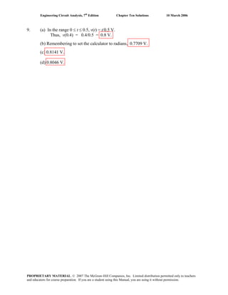
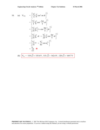
![Engineering Circuit Analysis, 7th
Edition Chapter Ten Solutions 10 March 2006
11. We begin by defining a clockwise current i. Then, KVL yields
–2×10⁻³
cos5t + 10i + vC = 0.
Since C
C
dv
i i C
dt
= = , we may rewrite our KVL equation as
3
30 2 10 cos5C
C
dv
v
dt
−
+ = × t [1]
We anticipate a response of the form vC(t) = Acos(5t + θ). Since 5 sin(5 )Cdv
A t
dt
θ= − + ,
we now may write Eq. [1] as –150Asin(5t + θ) + Acos(5t + θ) = 2×10⁻³
cos5t. Using a
common trigonometric identity, we may combine the two terms on the left hand side into
a single cosine function:
( )
2 2 1 150
150 cos 5 tan 2 10 cos5
A 3
A A t
A
θ − −⎛ ⎞
+ + + = ×⎜ ⎟
⎝ ⎠
t
Equating terms, we find that A = 13.33 μV and θ = –tan–1
150 = –89.62o
. Thus,
vC(t) = 13.33 cos (5t – 89.62o
) μV.
PROPRIETARY MATERIAL. © 2007 The McGraw-Hill Companies, Inc. Limited distribution permitted only to teachers
and educators for course preparation. If you are a student using this Manual, you are using it without permission.](https://image.slidesharecdn.com/xgizwmivsiwpds00swny-signature-f172ed6d5ea07afd7eea979324352a9b3640d1cd0448b6e1a174e81551e308e0-poli-140819203045-phpapp01/85/Engineering-circuit-analysis_solutions_7ed_-hayt-626-320.jpg)
![Engineering Circuit Analysis, 7th
Edition Chapter Ten Solutions 10 March 2006
12. KVL yields
–6cos400t + 100i + vL = 0.
Since 2L
di di
v L
dt dt
= = , we may rewrite our KVL equation as
2 100 6cos400
di
i
dt
+ = t [1]
We anticipate a response of the form i(t) = Acos(400t + θ). Since
400 sin(400 )
di
A t
dt
θ= − + ,
we now may write Eq. [1] as
–800Asin(400t + θ) + 100Acos(400t + θ) = 6 cos400t.
Using a common trigonometric identity, we may combine the two terms on the left hand
side into a single cosine function:
( ) ( )
2 2 1 800
800 100 cos 400 tan 6cos400
100
A
A A t
A
θ −⎛ ⎞
+ + + =⎜ ⎟
⎝ ⎠
t
Equating terms, we find that A = 7.442 mA and θ = –tan–1
8 = –82.88o
. Thus,
i(t) = 7.442 cos (400t – 82.88o
) mV, so 2L
di di
v L
dt dt
= = = 5.954cos (400t + 7.12o
)
PROPRIETARY MATERIAL. © 2007 The McGraw-Hill Companies, Inc. Limited distribution permitted only to teachers
and educators for course preparation. If you are a student using this Manual, you are using it without permission.](https://image.slidesharecdn.com/xgizwmivsiwpds00swny-signature-f172ed6d5ea07afd7eea979324352a9b3640d1cd0448b6e1a174e81551e308e0-poli-140819203045-phpapp01/85/Engineering-circuit-analysis_solutions_7ed_-hayt-627-320.jpg)
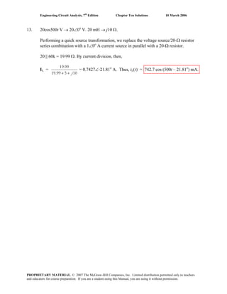
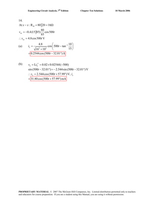
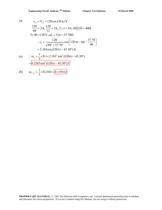
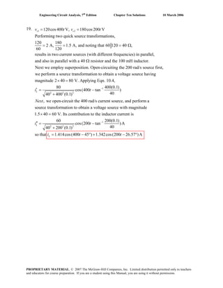
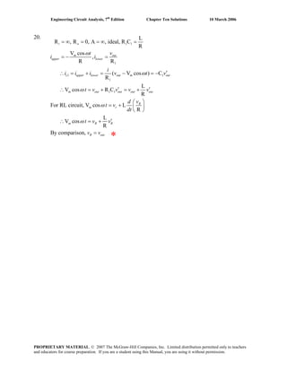
![Engineering Circuit Analysis, 7th
Edition Chapter Ten Solutions 10 March 2006
21. 1
(a) V cos R (ignore I.C)
C
1
V sin R
= +
′∴− = +
∫m
m
t i idt
t i i
C
ω
ω ω
(b)
( )1
ssume Acos( )
A
V sin R Asin ( ) cos( )
C
A A
V sin R Acos sin R Asin cos cos cos sin sin
C C
Equating terms on the left and right side,
A 1
[1] R Asin cos tan so tan 1 CR ,
C CR
−
= + Φ
∴− = − + Φ + + Φ
∴− = − Φ Φ + Φ − Φ
Φ = Φ∴ Φ = Φ =
m
m
i t
t t t
t t t t t
A ω
ω ω ω ω ω
ω ω ω ω ω ω ω ω
ω ω
ω
2 2 2 2 2 2
2 2 2
2 2 2
2 2 2 2 2 2
1
2 2 2
and
CR A 1
[2] V R A
C1 C R 1 C R
CVA R C 1 A
V 1 C R A
C C1 C R 1 C R
CV 1
cos tan
CR1 C R
−
− = − −
+ +
⎡ ⎤+
∴ = = + ∴ =⎢ ⎥
+ +⎣ ⎦
⎛ ⎞
∴ = +⎜ ⎟
+ ⎝ ⎠
m
m
m
m
i t
ω
ω ω
ω ω
ωω
ω ω
ω ω
ω
ω
ωω
-
PROPRIETARY MATERIAL. © 2007 The McGraw-Hill Companies, Inc. Limited distribution permitted only to teachers
and educators for course preparation. If you are a student using this Manual, you are using it without permission.](https://image.slidesharecdn.com/xgizwmivsiwpds00swny-signature-f172ed6d5ea07afd7eea979324352a9b3640d1cd0448b6e1a174e81551e308e0-poli-140819203045-phpapp01/85/Engineering-circuit-analysis_solutions_7ed_-hayt-636-320.jpg)
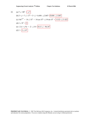
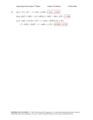
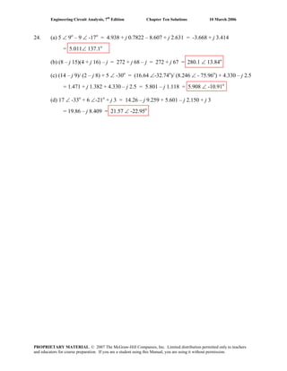
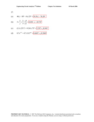
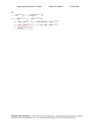
![Engineering Circuit Analysis, 7th
Edition Chapter Ten Solutions 10 March 2006
29.
(10 25 )
(10 25 ) (10 25 )
(10 25 )
(10 25 ) (10 25 )
(10 25 ) (10 25 )
(10 125.62 )
20 A
0.2 [20 ] 40
80
(80 40) , 0.08(80 40) 10
( 32 64) ( 12 64)
65.12 A
j t
L
j t t
L
j t
R
j t j t
s c
j t j t
c s
j t
s
i e
d
v e j e
dt
v e
v j e i j j e
i j e i j e
i e
+ °
+ ° = °
+ °
+ ° + °
+ ° + °
+ °
=
= =
=
= + = +
∴ = − + ∴ = − +
∴ =
PROPRIETARY MATERIAL. © 2007 The McGraw-Hill Companies, Inc. Limited distribution permitted only to teachers
and educators for course preparation. If you are a student using this Manual, you are using it without permission.](https://image.slidesharecdn.com/xgizwmivsiwpds00swny-signature-f172ed6d5ea07afd7eea979324352a9b3640d1cd0448b6e1a174e81551e308e0-poli-140819203045-phpapp01/85/Engineering-circuit-analysis_solutions_7ed_-hayt-644-320.jpg)
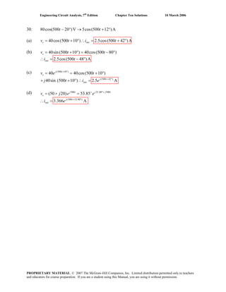

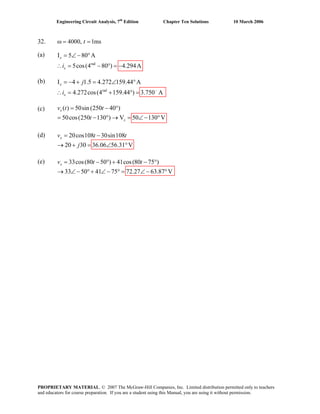
![Engineering Circuit Analysis, 7th
Edition Chapter Ten Solutions 10 March 2006
33. V1 2
3rad
rad rad
10 90 mV, 500; V 8 90 mV,
1200, M by 5, 0.5ms
( 5) [10cos(500 0.5 10 90 )
8cos(1.2 0.5 90 )]
50sin 0.25 40sin 0.6 34.96mV
out
t
v −
= ∠ ° ω = = ∠ °
ω = − =
= − × × + °
+ × + °
= + =
PROPRIETARY MATERIAL. © 2007 The McGraw-Hill Companies, Inc. Limited distribution permitted only to teachers
and educators for course preparation. If you are a student using this Manual, you are using it without permission.](https://image.slidesharecdn.com/xgizwmivsiwpds00swny-signature-f172ed6d5ea07afd7eea979324352a9b3640d1cd0448b6e1a174e81551e308e0-poli-140819203045-phpapp01/85/Engineering-circuit-analysis_solutions_7ed_-hayt-648-320.jpg)
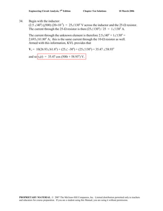
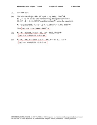
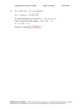
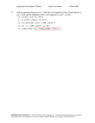
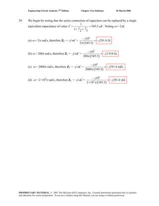
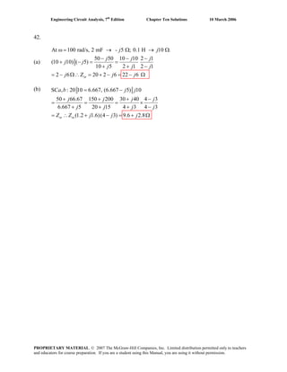
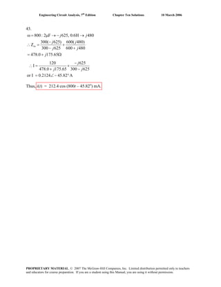
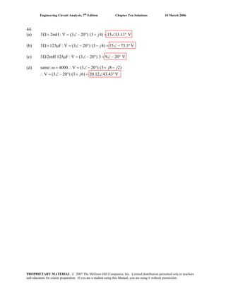
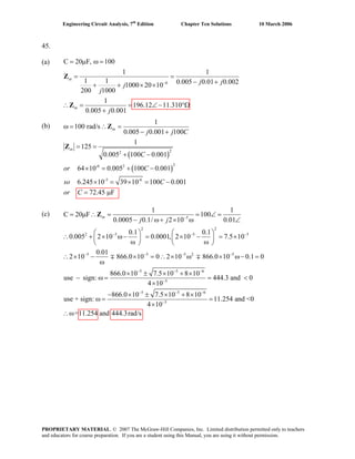
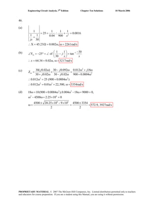
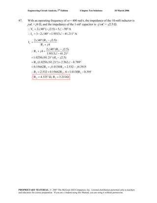
![Engineering Circuit Analysis, 7th
Edition Chapter Ten Solutions 10 March 2006
48. ω = 1200 rad/s.
(a)
2
2
1200
(200 80) (80 200 )[200 ( 80)]
200 (80 ) 40,000 6400 160
X 0 40,000 80 6400 0
1
46,400 80 , 580 1.437 F
1200
in
in
j j x j x j x
j x x x
x x x
x x C
C
ω =
− × + − + −
= =
+ − + − +
= ∴− + − =
∴ = = Ω = ∴ = μ
Z
(b)
2 2
2
2 2 2
2
80X 200X
100
200 (80 X)
6400X 40,000X
10,000
40,000 6400 160X X
0.64X 4X X 160X 46,400
3.64X 160 46,400 0,
160 25,600 675,600 160 837.4
X
7.28 7.28
1
X 93.05 ( 0) C 8.956 F∴ = μ
1200C
in in
j
j
X
−
−
= =
+ −
+
∴ =
+ − +
∴ + = − +
∴ + − =
− ± + − ±
= =
∴ = > =
Z Z
PROPRIETARY MATERIAL. © 2007 The McGraw-Hill Companies, Inc. Limited distribution permitted only to teachers
and educators for course preparation. If you are a student using this Manual, you are using it without permission.](https://image.slidesharecdn.com/xgizwmivsiwpds00swny-signature-f172ed6d5ea07afd7eea979324352a9b3640d1cd0448b6e1a174e81551e308e0-poli-140819203045-phpapp01/85/Engineering-circuit-analysis_solutions_7ed_-hayt-663-320.jpg)
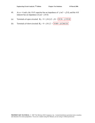
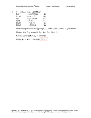
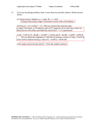
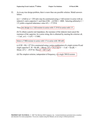
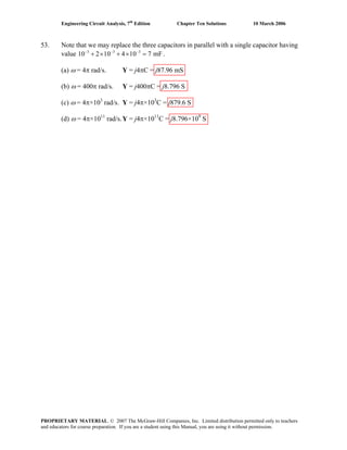
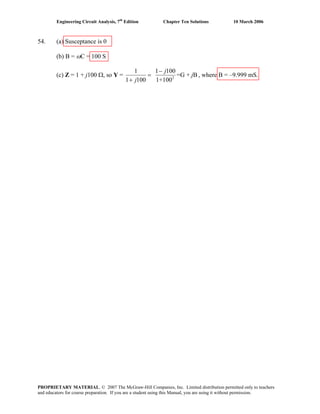
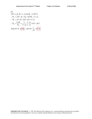
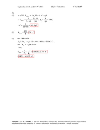
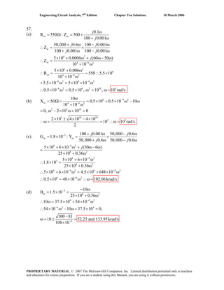
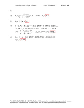
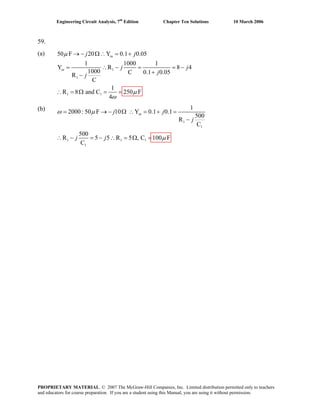
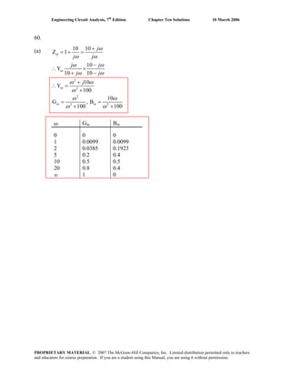
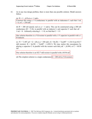
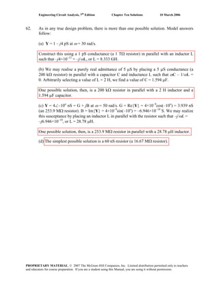
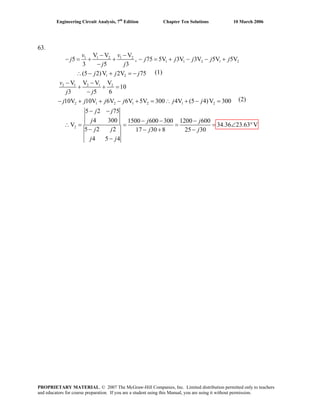
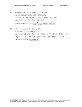
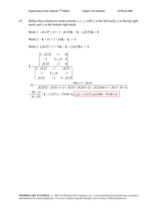
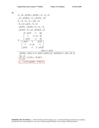
![Engineering Circuit Analysis, 7th
Edition Chapter Ten Solutions 10 March 2006
69.
(a) 1
1
1
1 1
1 1
1
1
1
R , R 0, A V / V 0
V AV
I C (V V )
R
V (1 A C R ) C R V
V
V AV (1 A C R ) C R V
V V
As A , C R
V
o o i
i
s i
f
i f f s
o
o i f f s
o o
(b)
A
C R A
V 1 A C R
f
f
s f
j
j
ω
ω s
j
j j
j j
j
ω
ω ω
ω ω
ω
= ∞ = = − >>
+
= = −
∴ + + =
= − ∴− + + =
∴ = −
+ +
→ ∞ → −
1
1
1 1
1 1
1 1
1
R1
R C
1 1 C RC
R
(V AV )
I (1 C R ) (V V ) C , V AV
R
V (1 A)(1 C R ) V C R C R V ,
V [(1 A)(1 C R ) C R ] C R V
V
[(1 A)(1 C R ) C R ] C R V
A
C R AV
V (1 A)(1
f
f f
f f
f
f
i
f f s i o i
f
i f f s f f i
i f f f f s
o
f f f f s
fo
s
jj
j j
j j j
j j j
j j j
j
j
ωω
ω ω
ω ω ω
ω ω ω
ω ω ω
ω
= =
++
+
= + = − = −
∴ + + = −
+ + + =
∴− + + + =
−
∴ =
+ +
1
1
C RV
As A ,
C R ) C R V 1 C R
fo
f f f s
j
j j
ω
ω ω ω
−
→ ∞ →
+ + f f
PROPRIETARY MATERIAL. © 2007 The McGraw-Hill Companies, Inc. Limited distribution permitted only to teachers
and educators for course preparation. If you are a student using this Manual, you are using it without permission.](https://image.slidesharecdn.com/xgizwmivsiwpds00swny-signature-f172ed6d5ea07afd7eea979324352a9b3640d1cd0448b6e1a174e81551e308e0-poli-140819203045-phpapp01/85/Engineering-circuit-analysis_solutions_7ed_-hayt-684-320.jpg)
![Engineering Circuit Analysis, 7th
Edition Chapter Ten Solutions 10 March 2006
70. Define the nodal voltage v1(t) at the junction between the two dependent sources.
The voltage source may be replaced by a 3∠-3o
V source, the 600-μF capacitor by a
–j/ 0.6 Ω impedance, the 500-μF capacitor by a –j2 Ω impedance, and the inductor by a
j2 Ω impedance.
5V2 + 3V2 =
2-
)-(
6.0/100
3-3- 21
o
1
jj
VVV
+
−
∠
[1]
-5V2 =
( )2 1 2
2 2j j
−
+
−
V V V
[2]
Solving, we find that V2 = 9.81 ∠ – 13.36o
mV.
Converting back to the time domain,
v2(t) = 9.81 cos (103
t – 13.36o
) mV
PROPRIETARY MATERIAL. © 2007 The McGraw-Hill Companies, Inc. Limited distribution permitted only to teachers
and educators for course preparation. If you are a student using this Manual, you are using it without permission.](https://image.slidesharecdn.com/xgizwmivsiwpds00swny-signature-f172ed6d5ea07afd7eea979324352a9b3640d1cd0448b6e1a174e81551e308e0-poli-140819203045-phpapp01/85/Engineering-circuit-analysis_solutions_7ed_-hayt-685-320.jpg)
![Engineering Circuit Analysis, 7th
Edition Chapter Ten Solutions 10 March 2006
71. Define three clockwise mesh currents: i1(t) in the left-most mesh, i2(t) in the bottom right
mesh, and i3(t) in the top right mesh. The 15-μF capacitor is replaced with a –j/ 0.15 Ω
impedance, the inductor is replaced by a j20 Ω impedance, the 74 μF capacitor is
replaced by a –j1.351 Ω impedance, the current source is replaced by a 2∠0o
mA source,
and the voltage source is replaced with a 5∠0o
V source.
Around the 1, 2 supermesh: (1 + j20) I1 + (13 – j1.351) I2 – 5 I3 = 0
and
–I1 + I2 = 2×10⁻³
Mesh 3: 5∠0o
– 5 I2 + (5 – j6.667) I3 = 0
Solving, we find that I1 = 148.0∠179.6o
mA. Converting to the time domain,
i1(t) = 148.0cos (104
t + 179.6o
) μA
Thus, P1Ω = [i1(1 ms)]2 •
1
= (16.15×10⁻³
)(1) W = 16.15 mW.
PROPRIETARY MATERIAL. © 2007 The McGraw-Hill Companies, Inc. Limited distribution permitted only to teachers
and educators for course preparation. If you are a student using this Manual, you are using it without permission.](https://image.slidesharecdn.com/xgizwmivsiwpds00swny-signature-f172ed6d5ea07afd7eea979324352a9b3640d1cd0448b6e1a174e81551e308e0-poli-140819203045-phpapp01/85/Engineering-circuit-analysis_solutions_7ed_-hayt-686-320.jpg)
![Engineering Circuit Analysis, 7th
Edition Chapter Ten Solutions 10 March 2006
72. We define an additional clockwise mesh current i4(t) flowing in the upper right-hand
mesh. The inductor is replaced by a j0.004 Ω impedance, the 750 μF capacitor is
replaced by a –j/ 0.0015 Ω impedance, and the 1000 μF capacitor is replaced by a –j/ 2
Ω impedance. We replace the left voltage source with a a 6 ∠ -13o
V source, and the
right voltage source with a 6 ∠ 0o
V source.
(1 – j/ 0.0015) I1 + j/0.0015I2 – I3 = 6 ∠ –13o
[1]
(0.005 + j/ 0.0015) I1 + (j0.004 – j/0.0015) I2 – j0.004 I4 = 0 [2]
–I1 + (1 – j500) I3 + j500 I4 = –6 ∠ 0o
[3]
–j0.004 I2 + j500I3 + (j0.004 – j500) I4 = 0 [4]
Solving, we find that
I1 = 2.002∠ –6.613o
mA, I2 = 2.038 ∠ –6.500o
mA, and I3 = 5.998 ∠ 179.8o
A.
Converting to the time domain,
i1(t) = 1.44 cos (2t – 6.613o
) mA
i2(t) = 2.038 cos (2t – 6.500o
) mA
i3(t) = 5.998 cos (2t + 179.8o
) A
PROPRIETARY MATERIAL. © 2007 The McGraw-Hill Companies, Inc. Limited distribution permitted only to teachers
and educators for course preparation. If you are a student using this Manual, you are using it without permission.](https://image.slidesharecdn.com/xgizwmivsiwpds00swny-signature-f172ed6d5ea07afd7eea979324352a9b3640d1cd0448b6e1a174e81551e308e0-poli-140819203045-phpapp01/85/Engineering-circuit-analysis_solutions_7ed_-hayt-687-320.jpg)
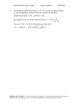
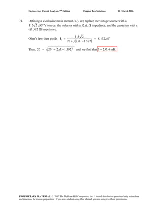
![Engineering Circuit Analysis, 7th
Edition Chapter Ten Solutions 10 March 2006
75. (a) By nodal analysis:
0 = (Vπ – 1)/ Rs + Vπ / RB + Vπ / rπ + jωCπ Vπ + (Vπ – Vout) jωCμ [1]
-gmVπ = (Vout – Vπ) jωCμ + Vout / RC + Vout / RL [2]
Simplify and collect terms:
( )
S
out
BS R
1
C-CC
r
1
R
1
R
1
=
⎥
⎥
⎦
⎤
⎢
⎢
⎣
⎡
++⎟⎟
⎠
⎞
⎜⎜
⎝
⎛
++ VV μπμπ
π
ωω jj [1]
(-gm + jωCμ) Vπ - (jωCμ + 1/RC + 1/RL) Vout = 0 [2]
Define
πr
1
R
1
R
1
R
1
BSS
++=
′
and
′
LR = RC || RL
Then ( ) ⎟
⎟
⎠
⎞
⎜
⎜
⎝
⎛
′
+
′
+
+++
′′
=Δ
SL
22
LS R
C
R
CC
C-CC2C
RR
1- μπμ
μπμμ ωω mgj
And Vout =
( ) ⎟
⎟
⎠
⎞
⎜
⎜
⎝
⎛
′
+
′
+
+++
′′
−
SL
22
LS
SSm
R
C
R
CC
C-CC2C
RR
1-
RCRg
μπμ
μπμμ
μ
ωω
ω
mgj
j
Therefore, ang(Vout) = ⎟⎟
⎠
⎞
⎜⎜
⎝
⎛ −−
2
1
tan
SmRg
Cj μω
-
( )
⎟
⎟
⎟
⎟
⎟
⎟
⎠
⎞
⎜
⎜
⎜
⎜
⎜
⎜
⎝
⎛
++
′′
⎟
⎟
⎠
⎞
⎜
⎜
⎝
⎛
′
+
′
+
+−
−
πμμ
μπμ
μ
ω
ω
CC2C
RR
1-
R
C
R
CC
C
tan
22
LS
SL1
mg
(b)
(c) The output is ~180o
out of phase with the input for f < 105
Hz; only for f = 0 is it
exactly 180o
out of phase with the input.
PROPRIETARY MATERIAL. © 2007 The McGraw-Hill Companies, Inc. Limited distribution permitted only to teachers
and educators for course preparation. If you are a student using this Manual, you are using it without permission.](https://image.slidesharecdn.com/xgizwmivsiwpds00swny-signature-f172ed6d5ea07afd7eea979324352a9b3640d1cd0448b6e1a174e81551e308e0-poli-140819203045-phpapp01/85/Engineering-circuit-analysis_solutions_7ed_-hayt-690-320.jpg)
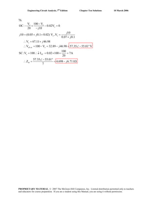
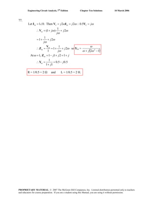
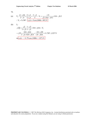
![Engineering Circuit Analysis, 7th
Edition Chapter Ten Solutions 10 March 2006
79.
,OC:V 0 V 1 0 V
SC: I V 2I 1 0 1[0.25( 2I ) I ] 2I
1 (0.5 2)I (0.5 1)I
I1
I 0.4 0.8 0.4 0.8
0.5 1 1 0
1 1 1 1
R 2.5 , 0.8, L 1.25H
0.4 L L 0.8
I 0.4 0.8 0.8944 63.43 A
L ab oc
N L N N N N
N N
N
N N
N N
N N
N
j j j j
j j j
j Y j
j
j
j j
j
ω
= ∴ = ∠ °
↓ ∴ = ∴ ∠ ° = − + +
∴ = − + = +
∴ = = − ∴ = = −
+ ∠ °
∴ = = Ω = = − = =
= − = ∠ − °
PROPRIETARY MATERIAL. © 2007 The McGraw-Hill Companies, Inc. Limited distribution permitted only to teachers
and educators for course preparation. If you are a student using this Manual, you are using it without permission.](https://image.slidesharecdn.com/xgizwmivsiwpds00swny-signature-f172ed6d5ea07afd7eea979324352a9b3640d1cd0448b6e1a174e81551e308e0-poli-140819203045-phpapp01/85/Engineering-circuit-analysis_solutions_7ed_-hayt-694-320.jpg)
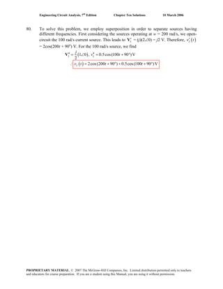
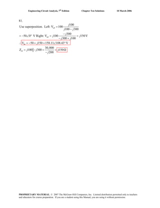
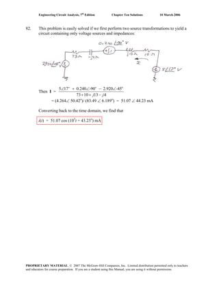
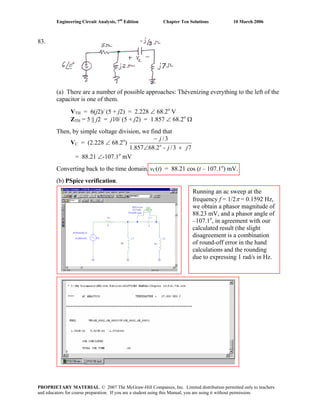
![Engineering Circuit Analysis, 7th
Edition Chapter Ten Solutions 10 March 2006
84. (a) Performing nodal analysis on the circuit,
Node 1: 1 = V1/ 5 + V1/ (-j10) + (V1 – V2)/ (-j5) + (V1 – V2)/ j10 [1]
Node 2: j0.5 = V2/ 10 + (V2 – V1)/ (-j5) + (V2 – V1)/ j10 [2]
Simplifying and collecting terms,
(0.2 + j0.2) V1 – j0.1 V2 = 1 [1]
-j V1 + (1 + j) V2 = j5 [2]
Solving, we find that V2 = VTH = 5.423 ∠ 40.60o
V
ZTH = 10 || [(j10 || -j5) + (5 || -j10)] = 10 || (-j10 + 4 – j2) = 5.882 – j3.529 Ω.
FREQ VM($N 0002,0) VP($N 0002,0)
1.592E+01 4.474E+00 1.165E+02
FREQ VM($N_0005,0) VP($N_0005,0)
1.592E+01 4.473E+00 1.165E+02
(b)
PROPRIETARY MATERIAL. © 2007 The McGraw-Hill Companies, Inc. Limited distribution permitted only to teachers
and educators for course preparation. If you are a student using this Manual, you are using it without permission.](https://image.slidesharecdn.com/xgizwmivsiwpds00swny-signature-f172ed6d5ea07afd7eea979324352a9b3640d1cd0448b6e1a174e81551e308e0-poli-140819203045-phpapp01/85/Engineering-circuit-analysis_solutions_7ed_-hayt-699-320.jpg)
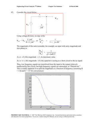
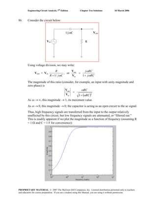
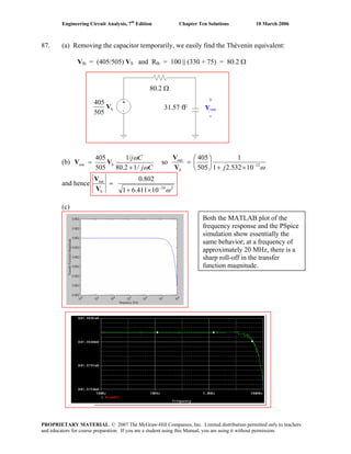
![Engineering Circuit Analysis, 7th
Edition Chapter Ten Solutions 10 March 2006
88. From the derivation, we see that
μ
μ
ω
ω
)CR||(R1
)CR||(R)R||(Rg-
LC
LCLCm
in
out
j
j
+
+
=
V
V
so that
2
1
2
2
LC
LC2
2
2
LC
LC2
2
LC
LC2
m
in
out
C
RR
RR
1
C
RR
RR
RR
RR
g
⎥
⎥
⎥
⎥
⎥
⎦
⎤
⎢
⎢
⎢
⎢
⎢
⎣
⎡
⎟⎟
⎠
⎞
⎜⎜
⎝
⎛
+
+
⎟⎟
⎠
⎞
⎜⎜
⎝
⎛
+
+⎟⎟
⎠
⎞
⎜⎜
⎝
⎛
+
=
μ
μ
ω
ω
V
V
This function has a maximum value of gm (RC || RL) at ω = 0. Thus, the capacitors reduce
the gain at high frequencies; this is the frequency regime at which they begin to act as
short circuits. Therefore, the maximum gain is obtained at frequencies at which the
capacitors may be treated as open circuits. If we do this, we may analyze the circuit
of Fig. 10.25b without the capacitors, which leads to
( )
BBS
B
LC
LC
m
BS
B
LC
LC
m
frequencylowS
out
Rr)Rr(R
Rr
RR
RR
g-
R||rR
R||r
RR
RR
g-
ππ
π
π
π
++⎟⎟
⎠
⎞
⎜⎜
⎝
⎛
+
=
+⎟⎟
⎠
⎞
⎜⎜
⎝
⎛
+
=
V
V
The resistor network comprised of rπ, RS, and RB acts as a voltage divider, leading to a
reduction in the gain of the amplifier. In the situation where rπ || RB >> RS, then it has
minimal effect and the gain will equal its “maximum” value of –gm (RC || RL).
(b) If we set RS = 100 Ω, RL = 8 Ω, RC | max = 10 kΩ and rπgm = 300, then we find that
B
B
m
S
tou
R||r100
R||r
(7.994)g-
π
π
+
=
V
V
We seek to maximize this term within the stated constraints. This requires a large value
of gm, but also a large value of rπ || RB. This parallel combination will be less than the
smaller of the two terms, so even if we allow RB → ∞, we are left with
ππ
π
r100
2398-
r100
rg
(7.994)- m
S
tou
+
=
+
≈
V
V
Considering this simpler expression, it is clear that if we select rπ to be small, (i.e.
rπ << 100), then gm will be large and the gain will have a maximum value of
approximately –23.98.
(c) Referring to our original expression in which the gain Vout/ Vin was computed, we
see that the critical frequency ωC = [(RC || RL) Cμ]-1
. Our selection of maximum RC,
RB → ∞, and rπ << 100 has not affected this frequency.
PROPRIETARY MATERIAL. © 2007 The McGraw-Hill Companies, Inc. Limited distribution permitted only to teachers
and educators for course preparation. If you are a student using this Manual, you are using it without permission.](https://image.slidesharecdn.com/xgizwmivsiwpds00swny-signature-f172ed6d5ea07afd7eea979324352a9b3640d1cd0448b6e1a174e81551e308e0-poli-140819203045-phpapp01/85/Engineering-circuit-analysis_solutions_7ed_-hayt-703-320.jpg)
![Engineering Circuit Analysis, 7th
Edition Chapter Ten Solutions 10 March 2006
89. Considering the ω = 2×10⁴
rad/ s source first, we make the following replacements:
100 cos (2×10⁴
t + 3o
) V → 100 ∠3o
V
33 μF → -j1.515 Ω 112 μH → j2.24 Ω 92 μF → -j0.5435 Ω
Then
(V1´ – 100 ∠ 3o
)/ 47×103
+ V1´/ (-j1.515) + (V1´ – V2´)/ (56×103
+ j4.48) = 0 [1]
(V2´ – V1´)/ (56×103
+ j4.48) + V2´/ (-j0.5435) = 0 [2]
Solving, we find that
V1´ = 3.223 ∠ -87o
mV and V2´ = 31.28 ∠ -177o
nV
Thus, v1´(t) = 3.223 cos (2×10⁴
t – 87o
) mV and v2´(t) = 31.28 cos(2×10⁴
t – 177o
) nV
Considering the effects of the ω = 2×10⁵
rad/ s source next,
100 cos (2×10⁵
t - 3o
) V → 100 ∠-3o
V
33 μF → -j0.1515 Ω 112 μH → j22.4 Ω 92 μF → -j0.05435 Ω
Then
V1"/ -j0.1515 + (V1" – V2")/ (56×103
+ j44.8) = 0 [3]
(V2" – V1")/ (56×103
+ j44.8) + (V2" – 100 ∠ 3o
)/ 47×103
+ V2"/ (-j0.05435) = 0 [4]
Solving, we find that
V1" = 312.8 ∠ 177o
pV and V2" = 115.7 ∠ -93o
μV
Thus,
v1"(t) = 312.8 cos (2×10⁵
t + 177o
) pV and v2"(t) = 115.7 cos(2×10⁵
t – 93o
) μV
Adding, we find
v1(t) = 3.223×10⁻³
cos (2×10⁴
t – 87o
) + 312.8×10⁻¹²
cos (2×10⁵
t + 177o
) V and
v2(t) = 31.28×10⁻⁹
cos(2×10⁴
t – 177o
) + 115.7×10⁻¹²
cos(2×10⁵
t – 93o
) V
PROPRIETARY MATERIAL. © 2007 The McGraw-Hill Companies, Inc. Limited distribution permitted only to teachers
and educators for course preparation. If you are a student using this Manual, you are using it without permission.](https://image.slidesharecdn.com/xgizwmivsiwpds00swny-signature-f172ed6d5ea07afd7eea979324352a9b3640d1cd0448b6e1a174e81551e308e0-poli-140819203045-phpapp01/85/Engineering-circuit-analysis_solutions_7ed_-hayt-704-320.jpg)
![Engineering Circuit Analysis, 7th
Edition Chapter Ten Solutions 10 March 2006
90. For the source operating at ω = 4 rad/s,
7 cos 4t → 7∠ 0o
V, 1 H → j4 Ω, 500 mF → -j0.5 Ω, 3 H → j12 Ω, and 2 F → -j/ 8 Ω.
Then by mesh analysis, (define 4 clockwise mesh currents I1, I2, I3, I4 in the top left, top
right, bottom left and bottom right meshes, respectively):
(9.5 + j4) I1 – j4 I2 – 7 I3 - 4 I4 = 0 [1]
-j4 I1 + (3 + j3.5) I2 – 3 I4 = -7 [2]
-7 I1 + (12 – j/ 8) I3 + j/ 8 I4 = 0 [3]
-3 I2 + j/ 8 I3 + (4 + j11.875) I4 = 0 [4]
Solving, we find that I3 = 365.3 ∠ -166.1o
mA and I4 = 330.97 ∠ 72.66o
mA.
For the source operating at ω = 2 rad/s,
5.5 cos 2t → 5.5∠ 0o
V, 1 H → j2 Ω, 500 mF → -j Ω, 3 H → j6 Ω, and 2 F → -j/ 4 Ω.
Then by mesh analysis, (define 4 clockwise mesh currents IA, IB, IC, ID in the top left, top
right, bottom left and bottom right meshes, respectively):
(9.5 + j2) IA – j2 IB – 7 IC – 4 ID = 0 [1]
-j2 IA + (3 + j) IB – 3 ID = -7 [2]
-7 IA + (12 – j/ 4) IC + j/ 4 ID = 0 [3]
-3 I2 + j/ 4 IC + (4 + j5.75) ID = 0 [4]
Solving, we find that IC = 783.8 ∠ -4.427o
mA and ID = 134 ∠ -25.93o
mA.
V1´ = -j0.25 (I3 – I4) = 0.1517∠131.7o
V and V1" = -j0.25(IC – ID) = 0.1652∠-90.17o
V
V2´ = (1 + j6) I4 = 2.013∠155.2o
V and V2" = (1 + j6) ID = 0.8151∠54.61o
V
Converting back to the time domain,
v1(t) = 0.1517 cos (4t + 131.7o
) + 0.1652 cos (2t - 90.17o
) V
v2(t) = 2.013 cos (4t + 155.2o
) + 0.8151 cos (2t + 54.61o
) V
PROPRIETARY MATERIAL. © 2007 The McGraw-Hill Companies, Inc. Limited distribution permitted only to teachers
and educators for course preparation. If you are a student using this Manual, you are using it without permission.](https://image.slidesharecdn.com/xgizwmivsiwpds00swny-signature-f172ed6d5ea07afd7eea979324352a9b3640d1cd0448b6e1a174e81551e308e0-poli-140819203045-phpapp01/85/Engineering-circuit-analysis_solutions_7ed_-hayt-705-320.jpg)
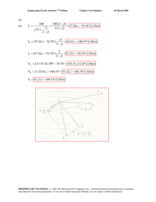
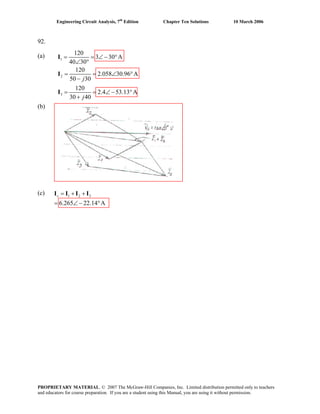
![Engineering Circuit Analysis, 7th
Edition Chapter Ten Solutions 10 March 2006
93.
1 2
1 2 1 2
1 2
2 2 2
I 5A, I 7A
I I 10 0 , I lags V,I leads V
I lags I . Use 2.5A /
[Analytically: 5 7 10
5cos 5sin 7cos 7sin
sin 1.4sin
5 1 1.4 sin 7 1 1sin 10
By SOLVE, 40.54 27.66 ]
in
j j
α β
α α β
α β
β β
β
= =
+ = ∠ °
∠ + ∠ =
= + + +
α β
∴ = −
∴ − + − =
= − ° = °
PROPRIETARY MATERIAL. © 2007 The McGraw-Hill Companies, Inc. Limited distribution permitted only to teachers
and educators for course preparation. If you are a student using this Manual, you are using it without permission.](https://image.slidesharecdn.com/xgizwmivsiwpds00swny-signature-f172ed6d5ea07afd7eea979324352a9b3640d1cd0448b6e1a174e81551e308e0-poli-140819203045-phpapp01/85/Engineering-circuit-analysis_solutions_7ed_-hayt-708-320.jpg)
![Engineering Circuit Analysis, 7th
Edition Chapter Ten Solutions 10 March 2006
94. V1 = 100∠0o
V, |V2| = 140 V, |V1 + V2| = 120 V.
Let 50 V = 1 inch. From the sketch, for ∠V2 positive,
V2 = 140∠122.5o
. We may also have V2 = 140∠-122.5o
V
[Analytically: |100 + 140∠α| = 120
so | 100 + 140 cos α + j140 sin α | = 120
Using the “Solve” routine of a scientific calculator,
α = ±122.88o
.]
PROPRIETARY MATERIAL. © 2007 The McGraw-Hill Companies, Inc. Limited distribution permitted only to teachers
and educators for course preparation. If you are a student using this Manual, you are using it without permission.](https://image.slidesharecdn.com/xgizwmivsiwpds00swny-signature-f172ed6d5ea07afd7eea979324352a9b3640d1cd0448b6e1a174e81551e308e0-poli-140819203045-phpapp01/85/Engineering-circuit-analysis_solutions_7ed_-hayt-709-320.jpg)
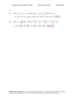
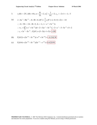
![Engineering Circuit Analysis, 7th
Edition Chapter Eleven Solutions 10 March 2006
4. We assume the circuit has already reached sinusoidal steady state by t = 0.
2.5 kΩ → 2.5 kΩ, 1 H → j1000 Ω, 4 μF → -j250 Ω, 10 kΩ → 10 kΩ
Zeq = j1000 || -j250 || 10000 = 11.10 – j333.0 Ω
Veq = o(20 30)(11.10 333.0)
2.631 50.54 V
2500 11.10 333.0
j
j
∠ −
= ∠ −
+ −
I10k = mA50.54-2631.0
10000
oeq
∠=
V
I1 H = mA140.5-631.2
1000
oeq
∠=
j
V
I4 μF = mA46.9352.10
250
oeq
∠=
− j
V
V2.5k = V55.3774.19
0.33310.112500
)2500)(3020( o
∠=
−+
∠
j
Thus, P2.5k =
[ ] mW97.97
2500
55.37cos74.19
2o
=
P1 H = ( )[ ][ ] mW3.395-)5.140cos(102.63154.50cos631.2 o-3o
=−×−
P4 μF = ( )[ ][ ] mW13.58)cos(39.461010.5254.50cos631.2 o-3o
=×−
P2.5k =
( )[ ] W279.6
10000
54.50cos631.2
2o
μ=
−
FREQ IM(V_PRINT1) IP(V_PRINT1)
1.592E+02 7.896E-03 3.755E+01
FREQ VM(R2_5k,$N_0002)VP(R2_5k,$N_0002)
1.592E+02 1.974E+01 3.755E+01
FREQ IM(V_PRINT2) IP(V_PRINT2)
1.592E+02 2.628E-03 -1.405E+02
FREQ VM(L,0) VP(L,0)
1.592E+02 2.629E+00 -5.054E+01
FREQ IM(V_PRINT11) IP(V_PRINT11)
1.592E+02 1.052E-02 3.946E+01
FREQ IM(V_PRINT12) IP(V_PRINT12)
1.592E+02 2.629E-04 -5.054E+01
PROPRIETARY MATERIAL. © 2007 The McGraw-Hill Companies, Inc. Limited distribution permitted only to teachers
and educators for course preparation. If you are a student using this Manual, you are using it without permission.](https://image.slidesharecdn.com/xgizwmivsiwpds00swny-signature-f172ed6d5ea07afd7eea979324352a9b3640d1cd0448b6e1a174e81551e308e0-poli-140819203045-phpapp01/85/Engineering-circuit-analysis_solutions_7ed_-hayt-713-320.jpg)
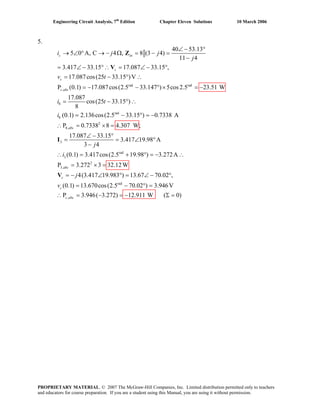
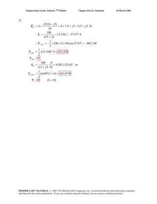
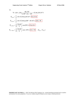
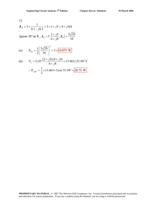
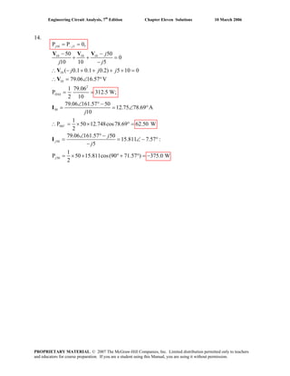
![Engineering Circuit Analysis, 7th
Edition Chapter Eleven Solutions 10 March 2006
15.
20
2 [1]
2 3
0 [2]
2 3
which simplify to
5 14 = 60 [1] and
2 + (3 2) = 0 [2]
Solving,
9.233 83.88 V and 5.122 140.2 V
1
P 9.
2
x x c
c
c c x
x c
x c
x c
gen
and
j
j j
− −
+ =
−
= +
−
−
−
= ∠ − ° = ∠ − °
= ×
V V V
V
V V V
V V
V V
V V
( )233 2 5.122 cos( 83.88 140.2 ) 26.22 W× × − °+ ° =
PROPRIETARY MATERIAL. © 2007 The McGraw-Hill Companies, Inc. Limited distribution permitted only to teachers
and educators for course preparation. If you are a student using this Manual, you are using it without permission.](https://image.slidesharecdn.com/xgizwmivsiwpds00swny-signature-f172ed6d5ea07afd7eea979324352a9b3640d1cd0448b6e1a174e81551e308e0-poli-140819203045-phpapp01/85/Engineering-circuit-analysis_solutions_7ed_-hayt-724-320.jpg)
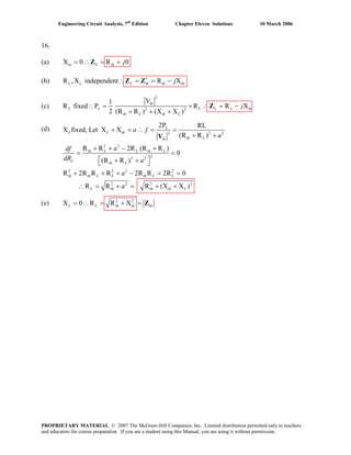
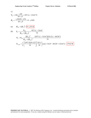
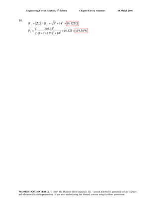
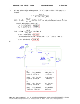
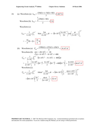
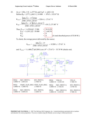
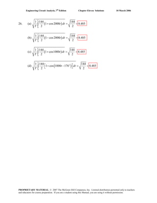
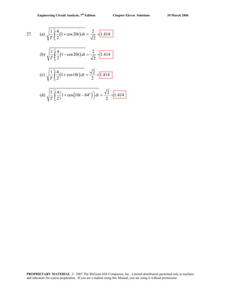
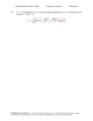
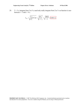
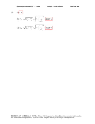
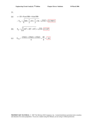
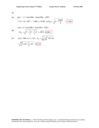
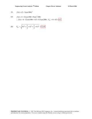
![Engineering Circuit Analysis, 7th
Edition Chapter Eleven Solutions 10 March 2006
34. (a) ieff = ( ) A6.4550)5(10
3
1 2
1
22
=⎥
⎦
⎤
⎢
⎣
⎡
+−+
(b) ieff = [ ] A2.236502020
2
1 2
1
1
0
==⎥
⎦
⎤
⎢
⎣
⎡
+⎟
⎠
⎞⎜
⎝
⎛ +−∫ dtt
(c) ieff = A2.257
2
cos
2
8-
4
2
sin8
1
1
1
0
2
1
1
0
=⎥
⎦
⎤
⎢
⎣
⎡
⎟
⎠
⎞
⎜
⎝
⎛
⎟
⎠
⎞
⎜
⎝
⎛
=⎥
⎦
⎤
⎢
⎣
⎡
⎟⎟
⎠
⎞
⎜⎜
⎝
⎛
⎟
⎠
⎞
⎜
⎝
⎛
∫
t
dtt
π
π
π
PROPRIETARY MATERIAL. © 2007 The McGraw-Hill Companies, Inc. Limited distribution permitted only to teachers
and educators for course preparation. If you are a student using this Manual, you are using it without permission.](https://image.slidesharecdn.com/xgizwmivsiwpds00swny-signature-f172ed6d5ea07afd7eea979324352a9b3640d1cd0448b6e1a174e81551e308e0-poli-140819203045-phpapp01/85/Engineering-circuit-analysis_solutions_7ed_-hayt-743-320.jpg)
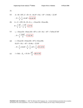
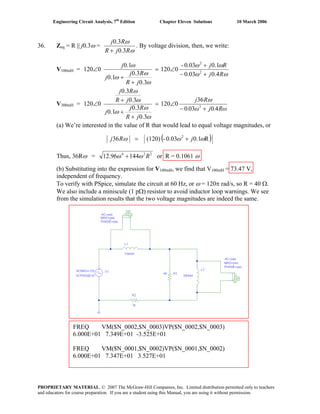
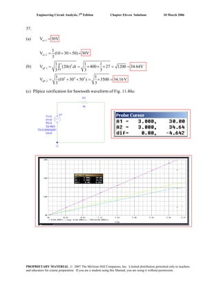
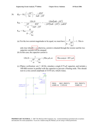
![Engineering Circuit Analysis, 7th
Edition Chapter Eleven Solutions 10 March 2006
39.
0.5( 3)
2
2
1,
0
5
( 3) 3 5
2, 3
3
2 2
2 3
( ) 10 [ ( ) ( 2)] 16 [ ( 3) ( 5)] V
Find eff. value separately
1 20
V 100 8 7.303
5 3
1 256
V 256 ( ) 6.654
5 5
V 7.303 6.654 9.879
1
V 100 256
5
t
eff
t t
eff
eff
t
eff
v t t u t u t e u t u t
t dt
e dt e e
t dt e e
− −
− − −
−
= − − + − − −
= = × =
= = − =
∴ = + =
= +
∫
∫
2 5
0 3
3 3 5
2
1 100
8 256 ( )
5 3
1 800
256(1 ) 9.879VOK
5 3
dt
e e e
e
− −
−
⎡ ⎤
⎢ ⎥⎣ ⎦
⎡ ⎤
= × + −⎢ ⎥⎣ ⎦
⎡ ⎤
= + − =⎢ ⎥⎣ ⎦
∫ ∫
PROPRIETARY MATERIAL. © 2007 The McGraw-Hill Companies, Inc. Limited distribution permitted only to teachers
and educators for course preparation. If you are a student using this Manual, you are using it without permission.](https://image.slidesharecdn.com/xgizwmivsiwpds00swny-signature-f172ed6d5ea07afd7eea979324352a9b3640d1cd0448b6e1a174e81551e308e0-poli-140819203045-phpapp01/85/Engineering-circuit-analysis_solutions_7ed_-hayt-748-320.jpg)
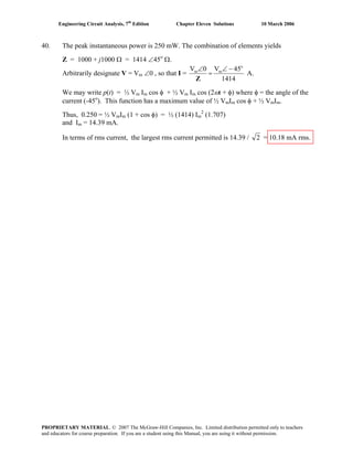
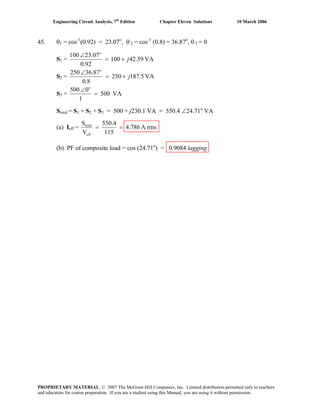
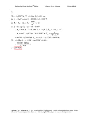
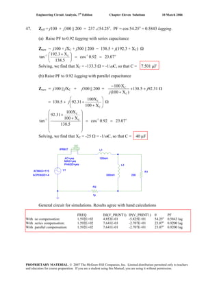
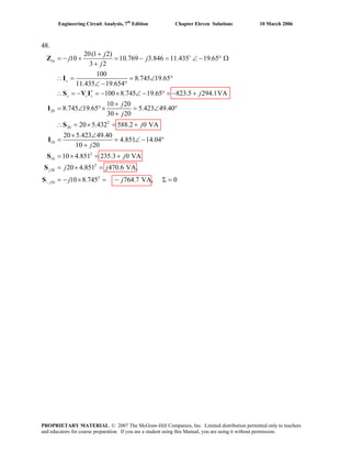
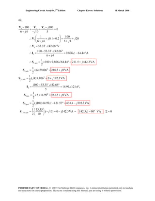
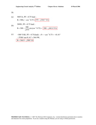
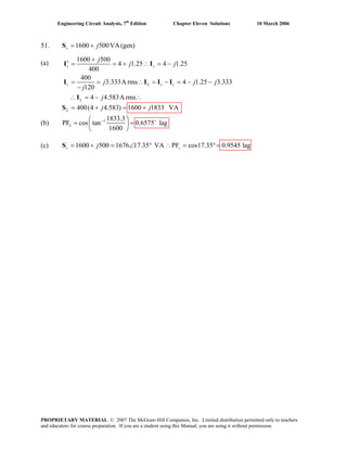
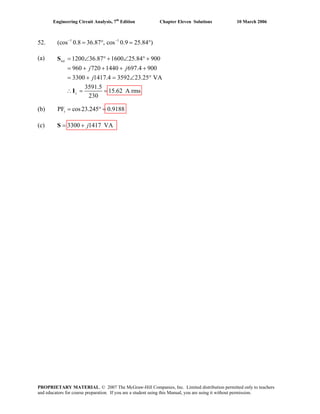

This document contains solutions to chapter 2 problems from the 7th Edition of Engineering Circuit Analysis. It includes 15 problems involving calculations of current, voltage, power, energy, and other circuit analysis variables. The solutions provide the step-by-step working to reach each numeric answer, and include diagrams in some cases. The document is copyrighted and intended only for educators in preparing course materials.


![[Solutions manual] elements of electromagnetics BY sadiku - 3rd](https://cdn.slidesharecdn.com/ss_thumbnails/solutionsmanualelementsofelectromagnetics-sadiku-3rd-150605143138-lva1-app6891-thumbnail.jpg?width=640&height=640&fit=bounds)
![Circuit Network Analysis - [Chapter4] Laplace Transform](https://cdn.slidesharecdn.com/ss_thumbnails/ch4-150613063858-lva1-app6891-thumbnail.jpg?width=640&height=640&fit=bounds)
![RF Module Design - [Chapter 8] Phase-Locked Loops](https://cdn.slidesharecdn.com/ss_thumbnails/rfch8-150613070348-lva1-app6892-thumbnail.jpg?width=640&height=640&fit=bounds)


![Circuit Network Analysis - [Chapter2] Sinusoidal Steady-state Analysis](https://cdn.slidesharecdn.com/ss_thumbnails/ch2-150613063856-lva1-app6892-thumbnail.jpg?width=640&height=640&fit=bounds)