SlideShare a Scribd company logo
1 of 49
Module III
Overview on Energy storage technologies
Electrochemical energy storage
• Primary batteries
• Secondary batteries
• Fuel cells
• Primary and secondary batteries utilise the chemical
components built into them, whereas fuel cells have
chemically bound energy supplied from the outside in the
form of synthetic fuel.
• Unlike secondary batteries, primary batteries cannot be
recharged when the built-in active chemicals have been
used, and therefore strictly they cannot be considered as
genuine energy storage.
Battery
• The battery has two circuits, one external and the other
internal.
• The internal circuit is comprised of the battery cell itself,
and provides the path through which the resultant ions
flow.
• The electrical circuit is closed by adding the external
circuit, thus providing the path through which the
electrons resulting from the oxidation reduction
reactions can flow.
• This external path is provided by the external system
(either a load or an energy source) to which the battery
is connected.
Battery
• The battery comprises of the following components:
– The electrodes
– Two pairs of electrochemically active substances
– The electrolyte
– The separator.
– The container
Battery
Battery
• Open circuit voltage V0 - The electric potential derived from
the chemical reactions by the two pairs of electrochemically
active substances, measured in the full charge state of the
cell when disconnected from any circuit.
• The open-circuit voltage is different from the voltage
measured in the cell during the discharging process, as
commonly presented in manufacturers’ datasheets.
Battery
• The discharge voltage
profile of the cell
depends on many
factors, such as
pressure and
temperature.
• The cell voltage and
the discharge current
rate are related and
determine the energy
capacity.
Battery parameters
• The energy capacity of batteries is defined as the usable
energy at a defined discharge rate(unit is Ah).
• The battery C rating is the measurement of current
which the battery is charged/discharged at. The
capacity of a battery is generally rated at 1C.
• Eg: A 10 Ah battery rated at 2C will give 20 A for 30 min
A 10 Ah battery rated at 0.2Cor C/5 will give 2 A for 5
hours
A 10 Ah battery rated at 0.5Cor C/2 will give 5 A for 2
hours
Battery parameters
• The ratio between the remaining energy capacity and
the rated capacity of the battery (at a defined discharge
rate) determines the state of charge (SoC) of the system.
• The energy efficiency can be formulated in terms of the
cell voltage and the theoretical maximum voltage
produced in the chemical reaction in the cell; the so-
called thermodynamic voltage.
• While charging, the energy efficiency in the cell is
defined as ÎĽc = V/Vth
• While discharging, the energy efficiency in the cell is defined
as ÎĽd = Vth/V
where Vth is the thermodynamic voltage and V is
the voltage between the cell terminals.
Battery parameters
• The discharging efficiency increases with the SoC.
• Likewise, the charging efficiency decays with the SoC.
• Therefore, to maximize the overall efficiency throughout
a full charge and discharge loop, an optimal average
SoC should be calculated.
• This duty is usually assigned to battery management
systems(BMS).
Battery parameters
• The depth of discharge(DoD) is defined as the maximum
fraction or percentage of a battery's capacity which can
be removed from the charged battery on a regular basis.
• Eg: A DoD of 80% means 80% charge can be discharged
during normal operation.
• DoD can also be used to express the currently drained
charge of the battery. Here DoD is the complement of
SoC: as one increases, the other decreases.
Battery parameters
• The specific energy capacity of a battery is
where n is the number of electrons transferred in a chemical reaction,
F is the Faraday constant in coulombs per mole, Vth is the theoretical
thermodynamic voltage of the cell, and ÎŁMi is the sum of the
molecular weights of the reactants of the cell.
• To optimize the specific energy, we must maximize Vth and
minimize ÎŁMi.
• The former is obtained by building up the two pairs of
electrochemically active substances with a highly
electropositive element and a highly electronegative element.
When that is done, the chemical reactions will yield a high
thermodynamic potential Vth.
• The latter is achieved by configuring cells based on reactants
with low atomic weights.
Battery parameters
• The specific power determines the maximum power that
the cell can deliver in relation to its weight.
• It depends on the open-circuit voltage of the cell, V0,
internal resistance Rint and the ohmic resistance of
conductors, Rc.
• This variable internal resistance, usually called the
overpotential, models a voltage drop in the cell and
depends on the amount of current drawn.
Lead-acid battery
• The lead-acid battery is the oldest chemical storage
device.
• The main drawbacks of these are comparatively low
energy density, long charge time and the need for careful
maintenance.
• It consists of alternate pairs of
plates, one lead and the other lead
coated with lead dioxide, immersed
in a dilute solution of sulphuric acid
that serves as an electrolyte.
• During discharge, both electrodes
are converted into lead sulphate.
• Charging restores the electrodes.
Lead-acid battery
• The performance of such a battery deteriorates gradually
because of irreversible physical changes in the electrodes;
ultimately, failure occurs between several hundred and
2000 cycles, depending on battery design and duty cycle.
• The reaction at the electrodes is given
Alkaline electrolyte batteries -
Ni-Zn battery
• The Ni-Zn battery is considered as a possible medium-
term EV system.
• The Ni-Zn cell’s main drawbacks are its short life cycle,
separator stability, temperature control, high cost and
mass production problems.
• Its short life cycle is the result of the high solubility of
the reaction products at the zinc electrodes.
Alkaline electrolyte batteries -
Ni-Fe battery
• The Ni-Fe battery is an alkaline storage battery using
KOH as the electrolyte.
• The main drawback of Ni-Fe batteries for electric vehicle
applications is their low energy density.
• The battery has a low peaking capability and other
drawbacks are low cell voltage and the low hydrogen
overvoltage of the iron electrode, which results in self-
discharge and low cell efficiency.
Alkaline electrolyte batteries -
Li-ion battery
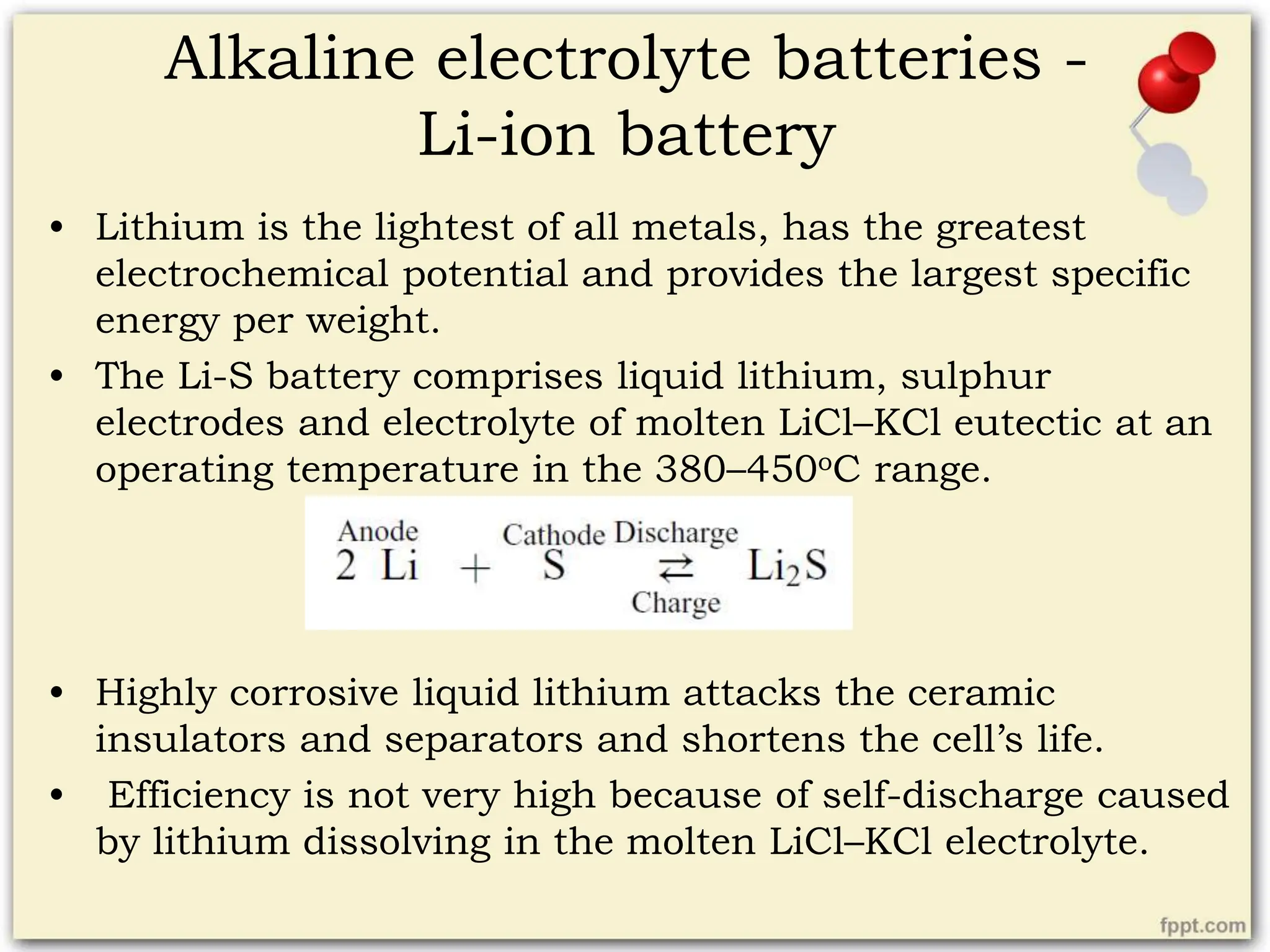
• Lithium is the lightest of all metals, has the greatest
electrochemical potential and provides the largest specific
energy per weight.
• The Li-S battery comprises liquid lithium, sulphur
electrodes and electrolyte of molten LiCl–KCl eutectic at an
operating temperature in the 380–450oC range.
• Highly corrosive liquid lithium attacks the ceramic
insulators and separators and shortens the cell’s life.
• Efficiency is not very high because of self-discharge caused
by lithium dissolving in the molten LiCl–KCl electrolyte.
Alkaline electrolyte batteries -
Li-ion battery
• The use of lithium–aluminium alloys and iron sulphide
as electrodes has led to the development of more
efficient Li-S cells with reasonable energy densities.
• The reactions in the cell can be written as follows:
or
Alkaline electrolyte batteries -
Li-ion battery
• The term lithium-ion is the name of batteries that share
similarities, but have different chemical fundamentals.
– Lithium Cobalt Oxide
– Lithium Manganese Oxide
– Lithium Nickel Manganese
– Lithium Nickel Cobalt Aluminium Oxide
– Lithium Iron Phosphate
– Lithium Titanate
The Flow Battery Energy Storage
System
• Flow batteries differ from conventional ones in the fact
that the electrolyte is not permanently stored in the cells
but, instead, two aqueous electrolytic solutions (A and
B) are contained in separate tanks.
• During the charging process, these aqueous solutions
are pumped through the electrochemical cells, where
the electrochemically active material dissolved in
electrolyte A is oxidized at the anode, and the
electrochemically active material in electrolyte B is
reduced at the cathode.
• The discharge cycle comprises the reverse process.
Flow Battery
The Vanadium Redox Battery
• Both the anode and cathode of the cells are composed of
catalyzed graphite.
• The aqueous electrolyte for both the anodic and the
cathodic regions is based on sulfuric acid, in which
vanadium sulfates are dissolved as active chemical
species.
• The anodic and cathodic regions are separated by a
polymer membrane, which permits ion exchange
between the two electrodes.
The Zinc–Bromine Battery
• The electrodes of ZBB cells are based on a carbon–
plastic composite.
• The separator between the anodic and cathodic regions
is made up of polyolefin sheets.
• The electrolyte is aqueous, containing dissolved zinc
bromide salts.
• Zn is the active chemical species at the anode (the
negative electrode), while Br is located at the cathode
(the positive electrode).
The Polysulfide–Bromide Flow
Battery
• In PSBs, the electrodes are based on a carbon–plastic
composite.
• The separator between the anodic and cathodic regions
is made up of polyolefin sheets.
• The aqueous electrolytes are based on sodium
polysulfide Na2Sy in the anodic region, and sodium
bromide NaBr in the cathodic one.
Flow Battery
• Flow batteries are easily scalable, since the volume of
the stored electrolyte determines the energy capacity of
the system.
• The power capacity depends on the number and size of
the electrochemical cells.
• They are suitable for storing energy over long periods of
time due to their very low self-discharge.
• Flow batteries can be fully discharged without any
damage, and in terms of cyclability, they present better
characteristics than conventional batteries.
• They require very low maintenance.
Fuel cells
• A fuel cell is an electrochemical cell that can
continuously change the chemical energy of a fuel and
oxidant to electrical energy with high efficiency.
• Fuel cells are comprised of two electrodes and an
electrolyte, which enables ion exchange between them.
• The anodic and cathodic regions are separated by a
polymeric membrane.
• To keep the reactions that create electricity going, these
cells need a constant supply of fuel and an oxidizing
agent.
• The types of electrolyte are diverse and determine the
performance of the cell; for example, the pressure of the
hydrogen produced and the operating temperature.
Fuel cells
• Electrolytes can be liquid or solid.
• Conventional electrolyzers use liquid alkaline
electrolytes, while modern ones use solid electrolytes.
The latter type is known as the proton exchange
membrane fuel cell (PEMFC).
• The synthetic fuels such as hydrogen, methanol,
ammonia and methane are used.
Fuel cells
• Fuel cells are distinguished from other secondary
batteries by their external fuel store.
• The mobile positive ions in the electrolyte may be metal
ions, produced by the metal anode supplying electrons
to the external circuit in the battery, while in a fuel cell
they may be HĂľ (H3OĂľ), produced by the hydrogen
supplied to the anode.
• The EMF of such a cell is E – (RT /nF) ln(a1/a2) – Nernst
eqn.
– where n is the number of electrons needed to get one atom or
molecule of X into its ionic form in the electrolyte, and a1 and a2
are the activities at electrodes 1 and 2.
Fuel cells
Fuel cells
• The essential functions of a fuel cell are
1. the charging (or electrolyser) function in which the
chemical AB is electrochemically decomposed to A and B;
2. the storage function in which A and B are held apart
3. the discharge (or fuel-cell) function in which A and B are
reunited, with the simultaneous generation of electricity.
• In secondary batteries, the electrolyser and fuel-cell
functions are combined within the same cell. This is a
convenient arrangement but is not essential.
• Fuel cells are attractive because of their high energy
density, lack of pollution and high cell efficiency.
• A good hydrogen or oxygen conductor has to be used as
the electrolyte.
Superconducting Magnetic Energy
Storage (SMES)
• The energy is stored in a magnetic field created by a DC
current flowing through a superconducting coil at
cryogenic temperatures.
• Superconductor materials present almost negligible
resistance while at cryogenic temperatures, so the
magnetic field in the coil can be created and maintained
with a very small amount of current flowing through it;
very little energy is dissipated by ohmic losses.
• The energy stored is determined by the self-inductance
of the coil L and the square of the electric current I.
Superconducting Magnetic Energy
Storage (SMES)
• There are two types of SMES systems, depending on the
working temperature of the coil: SMES systems based
on high-temperature coils (HTS) and low-temperature
coils (LTS).
• The former work at temperatures around 70 K, while the
latter work at temperatures around 5 K.
• Due to the very low energy consumption of the system’s
cryocoolers, the energy efficiency of SMES systems is
very high, at around 90%.
Superconducting coils
• Technical superconductors are normally made of NbTi
or Nb3Sn multi-filaments embedded in a copper or
aluminium stabilisation matrix.
• At present, Nb3Ti superconductors are mainly used for
reasons of ease of manufacture.
• If the superconductor
becomes normally
conducting, the
current transfers to
the stabilisation
matrix, thus avoiding
destruction of the
superconductor by
overheating.
Superconducting coils
• Since ferromagnetic materials do not apply to inductions
higher than 3T, coils for SMES are usually placed in air
or vacuum with ÎĽ = 1.
• To increase the magnetic energy stored, Wm with a given
current I, which is limited by the applied superconductor,
the total self-inductance L of the storage has to be made
as high as possible by choosing a suitable coil geometry.
• There are three concepts of SMES design:
– circular-shaped single solenoid
– series connection of coaxial solenoids
– circular, oval or D-shaped torus comprising series-connected single
coils.
Cryogenic systems
• The cryogenic system of an SMES device comprises a
refrigerator, where a coolant has to be prepared, and a
cryostat-storage vessel in which a superconducting coil is
placed to be refrigerated and thermally isolated from the
environment.
• The cooling system is usually based on liquid helium as
coolant, either in a helium bath or by forced circulation.
• It ensures that the superconductor temperature does not
exceed its critical value.
• Coil refrigeration and thermal insulation are extremely
difficult technical problems, since low temperatures
(around 1.8 K) are needed to enhance the superconductor’s
current-carrying ability.
SMES
Power extraction
• A superconducting coil is a source of variable direct
current.
• To couple this source to a constant voltage AC power
system, a special power transformation system is
required.
• By adjusting the thyristor’s delay angle, smooth and
rapid change of charge or discharge rate becomes
possible within one cycle of the power system frequency.
• A typical SMES configuration comprises two 6-pulse
thyristor Graetz bridges series-connected to the
superconducting coil on the DC part of the bridge and
coupled through an AC transformer to a power system
on the AC side of the bridge.
Basic circuit of SMES
Superconducting Magnetic Energy
Storage (SMES)
• An attractive feature of such a PTS is its high efficiency:
losses attributable to the solid-state bridge conversion
are estimated to be between 3% and 8% of the total
stored energy.
• When the phase delay angle p is less than 90, the bridge
operates in rectifier mode and acts as a load for the AC
power system.
• If p is set above 90, the average convertor voltage
becomes negative and the bridge becomes a kind of
power source for the AC system. So it operates in
inverter mode.
Superconducting Magnetic Energy
Storage (SMES)
• The major advantage of SMES systems is related to their
ability to inject or absorb vast amounts of energy in a
very short time.
• The cyclability of the system is very high, at up to 105
cycles at 100% of DoD.
• The use of SMES devices is limited to short-time storage
applications, as the self-discharge rates of the system
are relatively high, in the range of 10–15% of the rated
energy capacity per hour.
• It becomes completely discharged in a very short time,
discharging at full load in a matter of minutes or
seconds.
The Supercapacitor Energy Storage
System
• Supercapacitors are based on electrochemical cells that
contain two conductor electrodes, an electrolyte and a
porous membrane that permits the transit of ions
between the two electrodes.
• The main difference between supercapacitors and
batteries lies in the fact that no chemical reactions occur
in the cells, but the energy is stored electrostatically in
the cell.
• In supercapacitors, the electrodes and the electrolyte are
electrically charged. By applying a voltage between the
electrodes, both the electrodes and the electrolyte
become polarized.
The Supercapacitor Energy Storage
System
The Supercapacitor Energy Storage
System
• “Electrical double layers” are formed at the electrode
surfaces.
• The mechanism behind the operating principle of such a
double layer can be explained using the Helmholtz
model.
• The model establishes that the two layers are separated
by a layer of solvent molecules of the electrolyte.
• This layer of solvent molecules actually separates the
positive and negative charges of the electrode and
electrolyte, thus acting as a dielectric.
• Hence the double layer can be taken to resemble a
capacitor.
The Supercapacitor Energy Storage
System
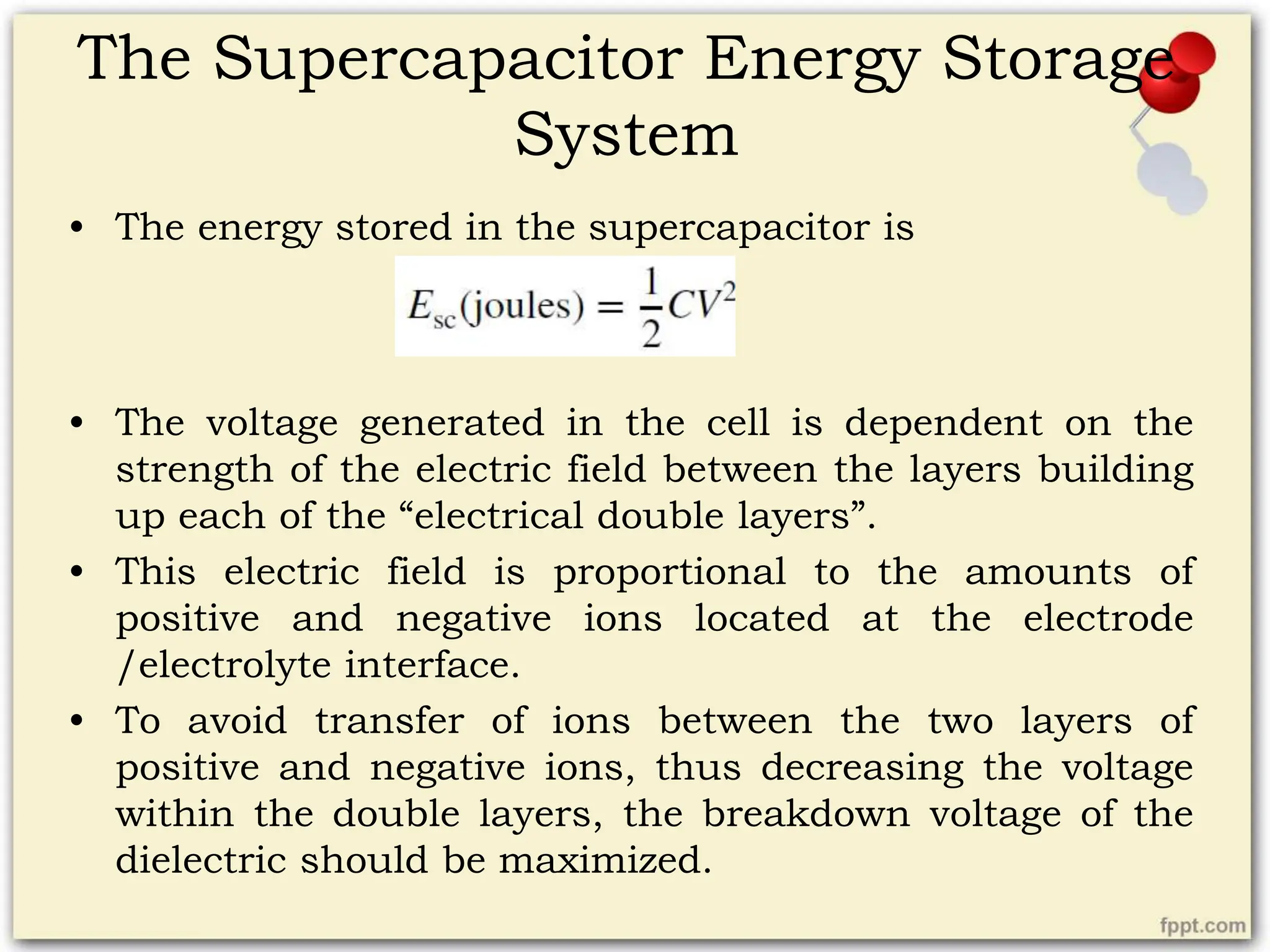
• The energy stored in the supercapacitor is
• The voltage generated in the cell is dependent on the
strength of the electric field between the layers building
up each of the “electrical double layers”.
• This electric field is proportional to the amounts of
positive and negative ions located at the electrode
/electrolyte interface.
• To avoid transfer of ions between the two layers of
positive and negative ions, thus decreasing the voltage
within the double layers, the breakdown voltage of the
dielectric should be maximized.
The Supercapacitor Energy Storage
System
• The selection of the electrolyte is key to ensuring the
maximum energy capacity.
• Both aqueous and organic electrolytes are commonly
found, the latter being the most common type.
• The second factor affecting the energy capacity of
supercapacitors is the capacitance of the cell.
• The capacitance is given by
where 𝜀 is the dielectric constant, 𝜀0 is the permittivity of a vacuum,
A is the effective area of the surface of the electrode, and d is the
dielectric thickness.
The Supercapacitor Energy Storage
System
• In order to maximize the capacitance, different metal-
oxide electrodes, electronically conducting polymer
electrodes and activated carbon electrodes, are used.
• These materials are porous, so as to maximize the
effective area of the electrode in which ions can be
allocated.
• The most common types are the ones based on activated
carbon, since they can lead to supercapacitors with a
high energy density and capacitances around 5000 F.
• The cell represented can be considered to resemble two
capacitors in series.
The Supercapacitor Energy Storage
System
• With reference to the supercapacitor dynamics, one
defining parameter is the so-called charge/discharge
time constant, 𝜏.
• This is given by the product of the equivalent series
resistance (ESR) of the supercapacitor and its
capacitance.
𝜏 = RC
• The ESR weights the losses in the supercapacitor while
charging and discharging.
• The third characteristic parameter for the supercapacitor
is the leakage resistance, which weights the self-
discharge of the cell.
• This resistance is much higher than the ESR.
The Supercapacitor Energy Storage
System
• Supercapacitors are characterized by offering high ramp
power rates, high cyclability, high efficiency and a high
specific power and power density. (10 times more than
for conventional batteries).
• The latter characteristic defines supercapacitors as well
suited for applications that impose major volumetric
restrictions.
• Major drawbacks of the technology are related to its
high self discharge rates and its limited applicability to
situations where high power and energy are needed.
• As a short-timescale ESS, supercapacitors are
unsuitable in that they are expensive in comparison
with other competitors such as flywheels.

More Related Content

What's hot

Laser micromachining seminar ppt
Laser micromachining  seminar pptLaser micromachining  seminar ppt
Laser micromachining seminar pptanil chaurasiya
 
Electron Beam Welding
Electron Beam WeldingElectron Beam Welding
Electron Beam Weldingfaheem maqsood
 
Posters for Exhibition
Posters for ExhibitionPosters for Exhibition
Posters for ExhibitionMohit Rajput
 
Laser and its applications
Laser and its applicationsLaser and its applications
Laser and its applicationsHabiba Arain
 
Arc welding types( carbon,TIG &MIG )
Arc welding types( carbon,TIG &MIG )Arc welding types( carbon,TIG &MIG )
Arc welding types( carbon,TIG &MIG )Pravinkumar
 
Wire arc additive manufacturing
Wire arc additive manufacturingWire arc additive manufacturing
Wire arc additive manufacturingDheerajKPanicker
 
Piezoelectric Materials
Piezoelectric MaterialsPiezoelectric Materials
Piezoelectric MaterialsMohammad Tawfik
 
Image attendance system
Image attendance systemImage attendance system
Image attendance systemMayank Garg
 
Electromagnetic bomb
Electromagnetic bombElectromagnetic bomb
Electromagnetic bombrj246
 
Micromachining Technology Seminar Presentation
Micromachining Technology Seminar PresentationMicromachining Technology Seminar Presentation
Micromachining Technology Seminar PresentationOrange Slides
 
Micro machining and classification, and Electro chemical micro machining Elec...
Micro machining and classification, and Electro chemical micro machining Elec...Micro machining and classification, and Electro chemical micro machining Elec...
Micro machining and classification, and Electro chemical micro machining Elec...Mustafa Memon
 
Micro Electrochemical Machining
Micro Electrochemical MachiningMicro Electrochemical Machining
Micro Electrochemical MachiningArbajAli
 
Ultrasonic Micro-machining
Ultrasonic Micro-machining Ultrasonic Micro-machining
Ultrasonic Micro-machining Amartya Roy
 
Multiferroic materials
Multiferroic materialsMultiferroic materials
Multiferroic materialsghulamalisajid
 
Geothermal energy technologies
Geothermal energy technologiesGeothermal energy technologies
Geothermal energy technologiesAkepati S. Reddy
 
ICTON 2014 - Third-and Fifth-order Optical Nonlinearities Characterization Us...
ICTON 2014 - Third-and Fifth-order Optical Nonlinearities Characterization Us...ICTON 2014 - Third-and Fifth-order Optical Nonlinearities Characterization Us...
ICTON 2014 - Third-and Fifth-order Optical Nonlinearities Characterization Us...Valentin Besse
 
Artificial Intelligence in Power Systems
Artificial Intelligence in Power SystemsArtificial Intelligence in Power Systems
Artificial Intelligence in Power Systemsmanogna gwen
 

What's hot (20)

Laser micromachining seminar ppt
Laser micromachining  seminar pptLaser micromachining  seminar ppt
Laser micromachining seminar ppt
 
Electron Beam Welding
Electron Beam WeldingElectron Beam Welding
Electron Beam Welding
 
Posters for Exhibition
Posters for ExhibitionPosters for Exhibition
Posters for Exhibition
 
Laser and its applications
Laser and its applicationsLaser and its applications
Laser and its applications
 
Arc welding types( carbon,TIG &MIG )
Arc welding types( carbon,TIG &MIG )Arc welding types( carbon,TIG &MIG )
Arc welding types( carbon,TIG &MIG )
 
Wire arc additive manufacturing
Wire arc additive manufacturingWire arc additive manufacturing
Wire arc additive manufacturing
 
Piezoelectric Materials
Piezoelectric MaterialsPiezoelectric Materials
Piezoelectric Materials
 
Image attendance system
Image attendance systemImage attendance system
Image attendance system
 
Electromagnetic bomb
Electromagnetic bombElectromagnetic bomb
Electromagnetic bomb
 
Laser micro machining
Laser micro machining Laser micro machining
Laser micro machining
 
Micromachining Technology Seminar Presentation
Micromachining Technology Seminar PresentationMicromachining Technology Seminar Presentation
Micromachining Technology Seminar Presentation
 
Micro machining and classification, and Electro chemical micro machining Elec...
Micro machining and classification, and Electro chemical micro machining Elec...Micro machining and classification, and Electro chemical micro machining Elec...
Micro machining and classification, and Electro chemical micro machining Elec...
 
FIBER OPTIC SENSORS
FIBER OPTIC SENSORSFIBER OPTIC SENSORS
FIBER OPTIC SENSORS
 
Micro Electrochemical Machining
Micro Electrochemical MachiningMicro Electrochemical Machining
Micro Electrochemical Machining
 
Ultrasonic Micro-machining
Ultrasonic Micro-machining Ultrasonic Micro-machining
Ultrasonic Micro-machining
 
Multiferroic materials
Multiferroic materialsMultiferroic materials
Multiferroic materials
 
Geothermal energy technologies
Geothermal energy technologiesGeothermal energy technologies
Geothermal energy technologies
 
Optical fiber sensors.ppt
Optical fiber sensors.pptOptical fiber sensors.ppt
Optical fiber sensors.ppt
 
ICTON 2014 - Third-and Fifth-order Optical Nonlinearities Characterization Us...
ICTON 2014 - Third-and Fifth-order Optical Nonlinearities Characterization Us...ICTON 2014 - Third-and Fifth-order Optical Nonlinearities Characterization Us...
ICTON 2014 - Third-and Fifth-order Optical Nonlinearities Characterization Us...
 
Artificial Intelligence in Power Systems
Artificial Intelligence in Power SystemsArtificial Intelligence in Power Systems
Artificial Intelligence in Power Systems
 

Similar to Energy storage systems notes module 3 ktu

MODULE - I : BATTERY TECHNOLOGY
MODULE - I : BATTERY TECHNOLOGYMODULE - I : BATTERY TECHNOLOGY
MODULE - I : BATTERY TECHNOLOGYrashmi m rashmi
 
battery.pdf
battery.pdfbattery.pdf
battery.pdfDarkGenius1
 
Energy storage systems for electric & hybrid vehicles
Energy storage systems for electric & hybrid vehiclesEnergy storage systems for electric & hybrid vehicles
Energy storage systems for electric & hybrid vehiclesS.K. Biradar
 
Energy storage systems for electric & hybrid vehicles
Energy storage systems for electric & hybrid vehiclesEnergy storage systems for electric & hybrid vehicles
Energy storage systems for electric & hybrid vehiclesCollege Of Engineering Pune
 
ev module 3.ppt.and notes of EV to kno6a
ev module 3.ppt.and notes of EV to kno6aev module 3.ppt.and notes of EV to kno6a
ev module 3.ppt.and notes of EV to kno6aAshokM259975
 
Battery Technology.pptx
Battery Technology.pptxBattery Technology.pptx
Battery Technology.pptxAprameya2
 
GROUP-1-AT212.pptx
GROUP-1-AT212.pptxGROUP-1-AT212.pptx
GROUP-1-AT212.pptxJesselynCea
 
Capacitor and Supercapacitor.pptx
Capacitor and Supercapacitor.pptxCapacitor and Supercapacitor.pptx
Capacitor and Supercapacitor.pptxShubhamPrajapati715991
 
Lecture 6 BATTERIES 2023.pptx
Lecture 6 BATTERIES 2023.pptxLecture 6 BATTERIES 2023.pptx
Lecture 6 BATTERIES 2023.pptxAdityaVashist12
 
Automobile 2 and 11 marks unit v
Automobile 2 and 11 marks unit vAutomobile 2 and 11 marks unit v
Automobile 2 and 11 marks unit vDasarathan Thandapani
 
Nuclear battery-A power point presentation
Nuclear battery-A power point presentationNuclear battery-A power point presentation
Nuclear battery-A power point presentationAditiPramanik
 
BATTERY.pptx presentation Introduction to Electric vehicles
BATTERY.pptx presentation Introduction to Electric vehiclesBATTERY.pptx presentation Introduction to Electric vehicles
BATTERY.pptx presentation Introduction to Electric vehiclesAlistairPinto
 
Basic cells and batteries
Basic cells and batteriesBasic cells and batteries
Basic cells and batteriesdesmondprince
 
UNIT-V-EV .pptx
UNIT-V-EV .pptxUNIT-V-EV .pptx
UNIT-V-EV .pptxSengolrajan
 
Lecture 2 construction of lead acid battery 2
Lecture 2 construction of lead acid battery   2Lecture 2 construction of lead acid battery   2
Lecture 2 construction of lead acid battery 2manfredhaule
 
UltraCapacitor
UltraCapacitorUltraCapacitor
UltraCapacitordhimancool
 

Similar to Energy storage systems notes module 3 ktu (20)

MODULE - I : BATTERY TECHNOLOGY
MODULE - I : BATTERY TECHNOLOGYMODULE - I : BATTERY TECHNOLOGY
MODULE - I : BATTERY TECHNOLOGY
 
battery.pdf
battery.pdfbattery.pdf
battery.pdf
 
Electrochemical energy storage
Electrochemical energy storageElectrochemical energy storage
Electrochemical energy storage
 
Energy storage systems for electric & hybrid vehicles
Energy storage systems for electric & hybrid vehiclesEnergy storage systems for electric & hybrid vehicles
Energy storage systems for electric & hybrid vehicles
 
Energy storage systems for electric & hybrid vehicles
Energy storage systems for electric & hybrid vehiclesEnergy storage systems for electric & hybrid vehicles
Energy storage systems for electric & hybrid vehicles
 
ev module 3.ppt.and notes of EV to kno6a
ev module 3.ppt.and notes of EV to kno6aev module 3.ppt.and notes of EV to kno6a
ev module 3.ppt.and notes of EV to kno6a
 
Battery Technology.pptx
Battery Technology.pptxBattery Technology.pptx
Battery Technology.pptx
 
Batteries
BatteriesBatteries
Batteries
 
GROUP-1-AT212.pptx
GROUP-1-AT212.pptxGROUP-1-AT212.pptx
GROUP-1-AT212.pptx
 
Capacitor and Supercapacitor.pptx
Capacitor and Supercapacitor.pptxCapacitor and Supercapacitor.pptx
Capacitor and Supercapacitor.pptx
 
Lecture 6 BATTERIES 2023.pptx
Lecture 6 BATTERIES 2023.pptxLecture 6 BATTERIES 2023.pptx
Lecture 6 BATTERIES 2023.pptx
 
Automobile 2 and 11 marks unit v
Automobile 2 and 11 marks unit vAutomobile 2 and 11 marks unit v
Automobile 2 and 11 marks unit v
 
Nuclear battery-A power point presentation
Nuclear battery-A power point presentationNuclear battery-A power point presentation
Nuclear battery-A power point presentation
 
Energy Storage.pdf
Energy Storage.pdfEnergy Storage.pdf
Energy Storage.pdf
 
Batteries and their types
Batteries and their typesBatteries and their types
Batteries and their types
 
BATTERY.pptx presentation Introduction to Electric vehicles
BATTERY.pptx presentation Introduction to Electric vehiclesBATTERY.pptx presentation Introduction to Electric vehicles
BATTERY.pptx presentation Introduction to Electric vehicles
 
Basic cells and batteries
Basic cells and batteriesBasic cells and batteries
Basic cells and batteries
 
UNIT-V-EV .pptx
UNIT-V-EV .pptxUNIT-V-EV .pptx
UNIT-V-EV .pptx
 
Lecture 2 construction of lead acid battery 2
Lecture 2 construction of lead acid battery   2Lecture 2 construction of lead acid battery   2
Lecture 2 construction of lead acid battery 2
 
UltraCapacitor
UltraCapacitorUltraCapacitor
UltraCapacitor
 

Recently uploaded

Introduction to Multiple Access Protocol.pptx
Introduction to Multiple Access Protocol.pptxIntroduction to Multiple Access Protocol.pptx
Introduction to Multiple Access Protocol.pptxupamatechverse
 
(ANVI) Koregaon Park Call Girls Just Call 7001035870 [ Cash on Delivery ] Pun...
(ANVI) Koregaon Park Call Girls Just Call 7001035870 [ Cash on Delivery ] Pun...(ANVI) Koregaon Park Call Girls Just Call 7001035870 [ Cash on Delivery ] Pun...
(ANVI) Koregaon Park Call Girls Just Call 7001035870 [ Cash on Delivery ] Pun...ranjana rawat
 
Porous Ceramics seminar and technical writing
Porous Ceramics seminar and technical writingPorous Ceramics seminar and technical writing
Porous Ceramics seminar and technical writingrakeshbaidya232001
 
Decoding Kotlin - Your guide to solving the mysterious in Kotlin.pptx
Decoding Kotlin - Your guide to solving the mysterious in Kotlin.pptxDecoding Kotlin - Your guide to solving the mysterious in Kotlin.pptx
Decoding Kotlin - Your guide to solving the mysterious in Kotlin.pptxJoĂŁo Esperancinha
 
MANUFACTURING PROCESS-II UNIT-2 LATHE MACHINE
MANUFACTURING PROCESS-II UNIT-2 LATHE MACHINEMANUFACTURING PROCESS-II UNIT-2 LATHE MACHINE
MANUFACTURING PROCESS-II UNIT-2 LATHE MACHINESIVASHANKAR N
 
Introduction and different types of Ethernet.pptx
Introduction and different types of Ethernet.pptxIntroduction and different types of Ethernet.pptx
Introduction and different types of Ethernet.pptxupamatechverse
 
High Profile Call Girls Nashik Megha 7001305949 Independent Escort Service Na...
High Profile Call Girls Nashik Megha 7001305949 Independent Escort Service Na...High Profile Call Girls Nashik Megha 7001305949 Independent Escort Service Na...
High Profile Call Girls Nashik Megha 7001305949 Independent Escort Service Na...Call Girls in Nagpur High Profile
 
Structural Analysis and Design of Foundations: A Comprehensive Handbook for S...
Structural Analysis and Design of Foundations: A Comprehensive Handbook for S...Structural Analysis and Design of Foundations: A Comprehensive Handbook for S...
Structural Analysis and Design of Foundations: A Comprehensive Handbook for S...Dr.Costas Sachpazis
 
Processing & Properties of Floor and Wall Tiles.pptx
Processing & Properties of Floor and Wall Tiles.pptxProcessing & Properties of Floor and Wall Tiles.pptx
Processing & Properties of Floor and Wall Tiles.pptxpranjaldaimarysona
 
(ANJALI) Dange Chowk Call Girls Just Call 7001035870 [ Cash on Delivery ] Pun...
(ANJALI) Dange Chowk Call Girls Just Call 7001035870 [ Cash on Delivery ] Pun...(ANJALI) Dange Chowk Call Girls Just Call 7001035870 [ Cash on Delivery ] Pun...
(ANJALI) Dange Chowk Call Girls Just Call 7001035870 [ Cash on Delivery ] Pun...ranjana rawat
 
Analog to Digital and Digital to Analog Converter
Analog to Digital and Digital to Analog ConverterAnalog to Digital and Digital to Analog Converter
Analog to Digital and Digital to Analog ConverterAbhinavSharma374939
 
SPICE PARK APR2024 ( 6,793 SPICE Models )
SPICE PARK APR2024 ( 6,793 SPICE Models )SPICE PARK APR2024 ( 6,793 SPICE Models )
SPICE PARK APR2024 ( 6,793 SPICE Models )Tsuyoshi Horigome
 
Coefficient of Thermal Expansion and their Importance.pptx
Coefficient of Thermal Expansion and their Importance.pptxCoefficient of Thermal Expansion and their Importance.pptx
Coefficient of Thermal Expansion and their Importance.pptxAsutosh Ranjan
 
VIP Call Girls Service Kondapur Hyderabad Call +91-8250192130
VIP Call Girls Service Kondapur Hyderabad Call +91-8250192130VIP Call Girls Service Kondapur Hyderabad Call +91-8250192130
VIP Call Girls Service Kondapur Hyderabad Call +91-8250192130Suhani Kapoor
 
Model Call Girl in Narela Delhi reach out to us at 🔝8264348440🔝
Model Call Girl in Narela Delhi reach out to us at 🔝8264348440🔝Model Call Girl in Narela Delhi reach out to us at 🔝8264348440🔝
Model Call Girl in Narela Delhi reach out to us at 🔝8264348440🔝soniya singh
 
(MEERA) Dapodi Call Girls Just Call 7001035870 [ Cash on Delivery ] Pune Escorts
(MEERA) Dapodi Call Girls Just Call 7001035870 [ Cash on Delivery ] Pune Escorts(MEERA) Dapodi Call Girls Just Call 7001035870 [ Cash on Delivery ] Pune Escorts
(MEERA) Dapodi Call Girls Just Call 7001035870 [ Cash on Delivery ] Pune Escortsranjana rawat
 
VIP Call Girls Service Hitech City Hyderabad Call +91-8250192130
VIP Call Girls Service Hitech City Hyderabad Call +91-8250192130VIP Call Girls Service Hitech City Hyderabad Call +91-8250192130
VIP Call Girls Service Hitech City Hyderabad Call +91-8250192130Suhani Kapoor
 
OSVC_Meta-Data based Simulation Automation to overcome Verification Challenge...
OSVC_Meta-Data based Simulation Automation to overcome Verification Challenge...OSVC_Meta-Data based Simulation Automation to overcome Verification Challenge...
OSVC_Meta-Data based Simulation Automation to overcome Verification Challenge...Soham Mondal
 
APPLICATIONS-AC/DC DRIVES-OPERATING CHARACTERISTICS
APPLICATIONS-AC/DC DRIVES-OPERATING CHARACTERISTICSAPPLICATIONS-AC/DC DRIVES-OPERATING CHARACTERISTICS
APPLICATIONS-AC/DC DRIVES-OPERATING CHARACTERISTICSKurinjimalarL3
 

Recently uploaded (20)

Introduction to Multiple Access Protocol.pptx
Introduction to Multiple Access Protocol.pptxIntroduction to Multiple Access Protocol.pptx
Introduction to Multiple Access Protocol.pptx
 
(ANVI) Koregaon Park Call Girls Just Call 7001035870 [ Cash on Delivery ] Pun...
(ANVI) Koregaon Park Call Girls Just Call 7001035870 [ Cash on Delivery ] Pun...(ANVI) Koregaon Park Call Girls Just Call 7001035870 [ Cash on Delivery ] Pun...
(ANVI) Koregaon Park Call Girls Just Call 7001035870 [ Cash on Delivery ] Pun...
 
Porous Ceramics seminar and technical writing
Porous Ceramics seminar and technical writingPorous Ceramics seminar and technical writing
Porous Ceramics seminar and technical writing
 
Decoding Kotlin - Your guide to solving the mysterious in Kotlin.pptx
Decoding Kotlin - Your guide to solving the mysterious in Kotlin.pptxDecoding Kotlin - Your guide to solving the mysterious in Kotlin.pptx
Decoding Kotlin - Your guide to solving the mysterious in Kotlin.pptx
 
MANUFACTURING PROCESS-II UNIT-2 LATHE MACHINE
MANUFACTURING PROCESS-II UNIT-2 LATHE MACHINEMANUFACTURING PROCESS-II UNIT-2 LATHE MACHINE
MANUFACTURING PROCESS-II UNIT-2 LATHE MACHINE
 
Introduction and different types of Ethernet.pptx
Introduction and different types of Ethernet.pptxIntroduction and different types of Ethernet.pptx
Introduction and different types of Ethernet.pptx
 
High Profile Call Girls Nashik Megha 7001305949 Independent Escort Service Na...
High Profile Call Girls Nashik Megha 7001305949 Independent Escort Service Na...High Profile Call Girls Nashik Megha 7001305949 Independent Escort Service Na...
High Profile Call Girls Nashik Megha 7001305949 Independent Escort Service Na...
 
Structural Analysis and Design of Foundations: A Comprehensive Handbook for S...
Structural Analysis and Design of Foundations: A Comprehensive Handbook for S...Structural Analysis and Design of Foundations: A Comprehensive Handbook for S...
Structural Analysis and Design of Foundations: A Comprehensive Handbook for S...
 
9953056974 Call Girls In South Ex, Escorts (Delhi) NCR.pdf
9953056974 Call Girls In South Ex, Escorts (Delhi) NCR.pdf9953056974 Call Girls In South Ex, Escorts (Delhi) NCR.pdf
9953056974 Call Girls In South Ex, Escorts (Delhi) NCR.pdf
 
Processing & Properties of Floor and Wall Tiles.pptx
Processing & Properties of Floor and Wall Tiles.pptxProcessing & Properties of Floor and Wall Tiles.pptx
Processing & Properties of Floor and Wall Tiles.pptx
 
(ANJALI) Dange Chowk Call Girls Just Call 7001035870 [ Cash on Delivery ] Pun...
(ANJALI) Dange Chowk Call Girls Just Call 7001035870 [ Cash on Delivery ] Pun...(ANJALI) Dange Chowk Call Girls Just Call 7001035870 [ Cash on Delivery ] Pun...
(ANJALI) Dange Chowk Call Girls Just Call 7001035870 [ Cash on Delivery ] Pun...
 
Analog to Digital and Digital to Analog Converter
Analog to Digital and Digital to Analog ConverterAnalog to Digital and Digital to Analog Converter
Analog to Digital and Digital to Analog Converter
 
SPICE PARK APR2024 ( 6,793 SPICE Models )
SPICE PARK APR2024 ( 6,793 SPICE Models )SPICE PARK APR2024 ( 6,793 SPICE Models )
SPICE PARK APR2024 ( 6,793 SPICE Models )
 
Coefficient of Thermal Expansion and their Importance.pptx
Coefficient of Thermal Expansion and their Importance.pptxCoefficient of Thermal Expansion and their Importance.pptx
Coefficient of Thermal Expansion and their Importance.pptx
 
VIP Call Girls Service Kondapur Hyderabad Call +91-8250192130
VIP Call Girls Service Kondapur Hyderabad Call +91-8250192130VIP Call Girls Service Kondapur Hyderabad Call +91-8250192130
VIP Call Girls Service Kondapur Hyderabad Call +91-8250192130
 
Model Call Girl in Narela Delhi reach out to us at 🔝8264348440🔝
Model Call Girl in Narela Delhi reach out to us at 🔝8264348440🔝Model Call Girl in Narela Delhi reach out to us at 🔝8264348440🔝
Model Call Girl in Narela Delhi reach out to us at 🔝8264348440🔝
 
(MEERA) Dapodi Call Girls Just Call 7001035870 [ Cash on Delivery ] Pune Escorts
(MEERA) Dapodi Call Girls Just Call 7001035870 [ Cash on Delivery ] Pune Escorts(MEERA) Dapodi Call Girls Just Call 7001035870 [ Cash on Delivery ] Pune Escorts
(MEERA) Dapodi Call Girls Just Call 7001035870 [ Cash on Delivery ] Pune Escorts
 
VIP Call Girls Service Hitech City Hyderabad Call +91-8250192130
VIP Call Girls Service Hitech City Hyderabad Call +91-8250192130VIP Call Girls Service Hitech City Hyderabad Call +91-8250192130
VIP Call Girls Service Hitech City Hyderabad Call +91-8250192130
 
OSVC_Meta-Data based Simulation Automation to overcome Verification Challenge...
OSVC_Meta-Data based Simulation Automation to overcome Verification Challenge...OSVC_Meta-Data based Simulation Automation to overcome Verification Challenge...
OSVC_Meta-Data based Simulation Automation to overcome Verification Challenge...
 
APPLICATIONS-AC/DC DRIVES-OPERATING CHARACTERISTICS
APPLICATIONS-AC/DC DRIVES-OPERATING CHARACTERISTICSAPPLICATIONS-AC/DC DRIVES-OPERATING CHARACTERISTICS
APPLICATIONS-AC/DC DRIVES-OPERATING CHARACTERISTICS
 

Energy storage systems notes module 3 ktu

  • 1. Module III Overview on Energy storage technologies
  • 2. Electrochemical energy storage • Primary batteries • Secondary batteries • Fuel cells • Primary and secondary batteries utilise the chemical components built into them, whereas fuel cells have chemically bound energy supplied from the outside in the form of synthetic fuel. • Unlike secondary batteries, primary batteries cannot be recharged when the built-in active chemicals have been used, and therefore strictly they cannot be considered as genuine energy storage.
  • 3. Battery • The battery has two circuits, one external and the other internal. • The internal circuit is comprised of the battery cell itself, and provides the path through which the resultant ions flow. • The electrical circuit is closed by adding the external circuit, thus providing the path through which the electrons resulting from the oxidation reduction reactions can flow. • This external path is provided by the external system (either a load or an energy source) to which the battery is connected.
  • 4. Battery • The battery comprises of the following components: – The electrodes – Two pairs of electrochemically active substances – The electrolyte – The separator. – The container
  • 6. Battery • Open circuit voltage V0 - The electric potential derived from the chemical reactions by the two pairs of electrochemically active substances, measured in the full charge state of the cell when disconnected from any circuit. • The open-circuit voltage is different from the voltage measured in the cell during the discharging process, as commonly presented in manufacturers’ datasheets.
  • 7. Battery • The discharge voltage profile of the cell depends on many factors, such as pressure and temperature. • The cell voltage and the discharge current rate are related and determine the energy capacity.
  • 8. Battery parameters • The energy capacity of batteries is defined as the usable energy at a defined discharge rate(unit is Ah). • The battery C rating is the measurement of current which the battery is charged/discharged at. The capacity of a battery is generally rated at 1C. • Eg: A 10 Ah battery rated at 2C will give 20 A for 30 min A 10 Ah battery rated at 0.2Cor C/5 will give 2 A for 5 hours A 10 Ah battery rated at 0.5Cor C/2 will give 5 A for 2 hours
  • 9. Battery parameters • The ratio between the remaining energy capacity and the rated capacity of the battery (at a defined discharge rate) determines the state of charge (SoC) of the system. • The energy efficiency can be formulated in terms of the cell voltage and the theoretical maximum voltage produced in the chemical reaction in the cell; the so- called thermodynamic voltage. • While charging, the energy efficiency in the cell is defined as ÎĽc = V/Vth • While discharging, the energy efficiency in the cell is defined as ÎĽd = Vth/V where Vth is the thermodynamic voltage and V is the voltage between the cell terminals.
  • 10. Battery parameters • The discharging efficiency increases with the SoC. • Likewise, the charging efficiency decays with the SoC. • Therefore, to maximize the overall efficiency throughout a full charge and discharge loop, an optimal average SoC should be calculated. • This duty is usually assigned to battery management systems(BMS).
  • 11. Battery parameters • The depth of discharge(DoD) is defined as the maximum fraction or percentage of a battery's capacity which can be removed from the charged battery on a regular basis. • Eg: A DoD of 80% means 80% charge can be discharged during normal operation. • DoD can also be used to express the currently drained charge of the battery. Here DoD is the complement of SoC: as one increases, the other decreases.
  • 12. Battery parameters • The specific energy capacity of a battery is where n is the number of electrons transferred in a chemical reaction, F is the Faraday constant in coulombs per mole, Vth is the theoretical thermodynamic voltage of the cell, and ÎŁMi is the sum of the molecular weights of the reactants of the cell. • To optimize the specific energy, we must maximize Vth and minimize ÎŁMi. • The former is obtained by building up the two pairs of electrochemically active substances with a highly electropositive element and a highly electronegative element. When that is done, the chemical reactions will yield a high thermodynamic potential Vth. • The latter is achieved by configuring cells based on reactants with low atomic weights.
  • 13. Battery parameters • The specific power determines the maximum power that the cell can deliver in relation to its weight. • It depends on the open-circuit voltage of the cell, V0, internal resistance Rint and the ohmic resistance of conductors, Rc. • This variable internal resistance, usually called the overpotential, models a voltage drop in the cell and depends on the amount of current drawn.
  • 14. Lead-acid battery • The lead-acid battery is the oldest chemical storage device. • The main drawbacks of these are comparatively low energy density, long charge time and the need for careful maintenance. • It consists of alternate pairs of plates, one lead and the other lead coated with lead dioxide, immersed in a dilute solution of sulphuric acid that serves as an electrolyte. • During discharge, both electrodes are converted into lead sulphate. • Charging restores the electrodes.
  • 15. Lead-acid battery • The performance of such a battery deteriorates gradually because of irreversible physical changes in the electrodes; ultimately, failure occurs between several hundred and 2000 cycles, depending on battery design and duty cycle. • The reaction at the electrodes is given
  • 16. Alkaline electrolyte batteries - Ni-Zn battery • The Ni-Zn battery is considered as a possible medium- term EV system. • The Ni-Zn cell’s main drawbacks are its short life cycle, separator stability, temperature control, high cost and mass production problems. • Its short life cycle is the result of the high solubility of the reaction products at the zinc electrodes.
  • 17. Alkaline electrolyte batteries - Ni-Fe battery • The Ni-Fe battery is an alkaline storage battery using KOH as the electrolyte. • The main drawback of Ni-Fe batteries for electric vehicle applications is their low energy density. • The battery has a low peaking capability and other drawbacks are low cell voltage and the low hydrogen overvoltage of the iron electrode, which results in self- discharge and low cell efficiency.
  • 18. Alkaline electrolyte batteries - Li-ion battery • Lithium is the lightest of all metals, has the greatest electrochemical potential and provides the largest specific energy per weight. • The Li-S battery comprises liquid lithium, sulphur electrodes and electrolyte of molten LiCl–KCl eutectic at an operating temperature in the 380–450oC range. • Highly corrosive liquid lithium attacks the ceramic insulators and separators and shortens the cell’s life. • Efficiency is not very high because of self-discharge caused by lithium dissolving in the molten LiCl–KCl electrolyte.
  • 19. Alkaline electrolyte batteries - Li-ion battery • The use of lithium–aluminium alloys and iron sulphide as electrodes has led to the development of more efficient Li-S cells with reasonable energy densities. • The reactions in the cell can be written as follows: or
  • 20. Alkaline electrolyte batteries - Li-ion battery • The term lithium-ion is the name of batteries that share similarities, but have different chemical fundamentals. – Lithium Cobalt Oxide – Lithium Manganese Oxide – Lithium Nickel Manganese – Lithium Nickel Cobalt Aluminium Oxide – Lithium Iron Phosphate – Lithium Titanate
  • 21. The Flow Battery Energy Storage System • Flow batteries differ from conventional ones in the fact that the electrolyte is not permanently stored in the cells but, instead, two aqueous electrolytic solutions (A and B) are contained in separate tanks. • During the charging process, these aqueous solutions are pumped through the electrochemical cells, where the electrochemically active material dissolved in electrolyte A is oxidized at the anode, and the electrochemically active material in electrolyte B is reduced at the cathode. • The discharge cycle comprises the reverse process.
  • 23. The Vanadium Redox Battery • Both the anode and cathode of the cells are composed of catalyzed graphite. • The aqueous electrolyte for both the anodic and the cathodic regions is based on sulfuric acid, in which vanadium sulfates are dissolved as active chemical species. • The anodic and cathodic regions are separated by a polymer membrane, which permits ion exchange between the two electrodes.
  • 24. The Zinc–Bromine Battery • The electrodes of ZBB cells are based on a carbon– plastic composite. • The separator between the anodic and cathodic regions is made up of polyolefin sheets. • The electrolyte is aqueous, containing dissolved zinc bromide salts. • Zn is the active chemical species at the anode (the negative electrode), while Br is located at the cathode (the positive electrode).
  • 25. The Polysulfide–Bromide Flow Battery • In PSBs, the electrodes are based on a carbon–plastic composite. • The separator between the anodic and cathodic regions is made up of polyolefin sheets. • The aqueous electrolytes are based on sodium polysulfide Na2Sy in the anodic region, and sodium bromide NaBr in the cathodic one.
  • 26. Flow Battery • Flow batteries are easily scalable, since the volume of the stored electrolyte determines the energy capacity of the system. • The power capacity depends on the number and size of the electrochemical cells. • They are suitable for storing energy over long periods of time due to their very low self-discharge. • Flow batteries can be fully discharged without any damage, and in terms of cyclability, they present better characteristics than conventional batteries. • They require very low maintenance.
  • 27. Fuel cells • A fuel cell is an electrochemical cell that can continuously change the chemical energy of a fuel and oxidant to electrical energy with high efficiency. • Fuel cells are comprised of two electrodes and an electrolyte, which enables ion exchange between them. • The anodic and cathodic regions are separated by a polymeric membrane. • To keep the reactions that create electricity going, these cells need a constant supply of fuel and an oxidizing agent. • The types of electrolyte are diverse and determine the performance of the cell; for example, the pressure of the hydrogen produced and the operating temperature.
  • 28. Fuel cells • Electrolytes can be liquid or solid. • Conventional electrolyzers use liquid alkaline electrolytes, while modern ones use solid electrolytes. The latter type is known as the proton exchange membrane fuel cell (PEMFC). • The synthetic fuels such as hydrogen, methanol, ammonia and methane are used.
  • 29. Fuel cells • Fuel cells are distinguished from other secondary batteries by their external fuel store. • The mobile positive ions in the electrolyte may be metal ions, produced by the metal anode supplying electrons to the external circuit in the battery, while in a fuel cell they may be HĂľ (H3OĂľ), produced by the hydrogen supplied to the anode. • The EMF of such a cell is E – (RT /nF) ln(a1/a2) – Nernst eqn. – where n is the number of electrons needed to get one atom or molecule of X into its ionic form in the electrolyte, and a1 and a2 are the activities at electrodes 1 and 2.
  • 31. Fuel cells • The essential functions of a fuel cell are 1. the charging (or electrolyser) function in which the chemical AB is electrochemically decomposed to A and B; 2. the storage function in which A and B are held apart 3. the discharge (or fuel-cell) function in which A and B are reunited, with the simultaneous generation of electricity. • In secondary batteries, the electrolyser and fuel-cell functions are combined within the same cell. This is a convenient arrangement but is not essential. • Fuel cells are attractive because of their high energy density, lack of pollution and high cell efficiency. • A good hydrogen or oxygen conductor has to be used as the electrolyte.
  • 32. Superconducting Magnetic Energy Storage (SMES) • The energy is stored in a magnetic field created by a DC current flowing through a superconducting coil at cryogenic temperatures. • Superconductor materials present almost negligible resistance while at cryogenic temperatures, so the magnetic field in the coil can be created and maintained with a very small amount of current flowing through it; very little energy is dissipated by ohmic losses. • The energy stored is determined by the self-inductance of the coil L and the square of the electric current I.
  • 33. Superconducting Magnetic Energy Storage (SMES) • There are two types of SMES systems, depending on the working temperature of the coil: SMES systems based on high-temperature coils (HTS) and low-temperature coils (LTS). • The former work at temperatures around 70 K, while the latter work at temperatures around 5 K. • Due to the very low energy consumption of the system’s cryocoolers, the energy efficiency of SMES systems is very high, at around 90%.
  • 34. Superconducting coils • Technical superconductors are normally made of NbTi or Nb3Sn multi-filaments embedded in a copper or aluminium stabilisation matrix. • At present, Nb3Ti superconductors are mainly used for reasons of ease of manufacture. • If the superconductor becomes normally conducting, the current transfers to the stabilisation matrix, thus avoiding destruction of the superconductor by overheating.
  • 35. Superconducting coils • Since ferromagnetic materials do not apply to inductions higher than 3T, coils for SMES are usually placed in air or vacuum with ÎĽ = 1. • To increase the magnetic energy stored, Wm with a given current I, which is limited by the applied superconductor, the total self-inductance L of the storage has to be made as high as possible by choosing a suitable coil geometry. • There are three concepts of SMES design: – circular-shaped single solenoid – series connection of coaxial solenoids – circular, oval or D-shaped torus comprising series-connected single coils.
  • 36. Cryogenic systems • The cryogenic system of an SMES device comprises a refrigerator, where a coolant has to be prepared, and a cryostat-storage vessel in which a superconducting coil is placed to be refrigerated and thermally isolated from the environment. • The cooling system is usually based on liquid helium as coolant, either in a helium bath or by forced circulation. • It ensures that the superconductor temperature does not exceed its critical value. • Coil refrigeration and thermal insulation are extremely difficult technical problems, since low temperatures (around 1.8 K) are needed to enhance the superconductor’s current-carrying ability.
  • 37. SMES
  • 38. Power extraction • A superconducting coil is a source of variable direct current. • To couple this source to a constant voltage AC power system, a special power transformation system is required. • By adjusting the thyristor’s delay angle, smooth and rapid change of charge or discharge rate becomes possible within one cycle of the power system frequency. • A typical SMES configuration comprises two 6-pulse thyristor Graetz bridges series-connected to the superconducting coil on the DC part of the bridge and coupled through an AC transformer to a power system on the AC side of the bridge.
  • 40. Superconducting Magnetic Energy Storage (SMES) • An attractive feature of such a PTS is its high efficiency: losses attributable to the solid-state bridge conversion are estimated to be between 3% and 8% of the total stored energy. • When the phase delay angle p is less than 90, the bridge operates in rectifier mode and acts as a load for the AC power system. • If p is set above 90, the average convertor voltage becomes negative and the bridge becomes a kind of power source for the AC system. So it operates in inverter mode.
  • 41. Superconducting Magnetic Energy Storage (SMES) • The major advantage of SMES systems is related to their ability to inject or absorb vast amounts of energy in a very short time. • The cyclability of the system is very high, at up to 105 cycles at 100% of DoD. • The use of SMES devices is limited to short-time storage applications, as the self-discharge rates of the system are relatively high, in the range of 10–15% of the rated energy capacity per hour. • It becomes completely discharged in a very short time, discharging at full load in a matter of minutes or seconds.
  • 42. The Supercapacitor Energy Storage System • Supercapacitors are based on electrochemical cells that contain two conductor electrodes, an electrolyte and a porous membrane that permits the transit of ions between the two electrodes. • The main difference between supercapacitors and batteries lies in the fact that no chemical reactions occur in the cells, but the energy is stored electrostatically in the cell. • In supercapacitors, the electrodes and the electrolyte are electrically charged. By applying a voltage between the electrodes, both the electrodes and the electrolyte become polarized.
  • 43. The Supercapacitor Energy Storage System
  • 44. The Supercapacitor Energy Storage System • “Electrical double layers” are formed at the electrode surfaces. • The mechanism behind the operating principle of such a double layer can be explained using the Helmholtz model. • The model establishes that the two layers are separated by a layer of solvent molecules of the electrolyte. • This layer of solvent molecules actually separates the positive and negative charges of the electrode and electrolyte, thus acting as a dielectric. • Hence the double layer can be taken to resemble a capacitor.
  • 45. The Supercapacitor Energy Storage System • The energy stored in the supercapacitor is • The voltage generated in the cell is dependent on the strength of the electric field between the layers building up each of the “electrical double layers”. • This electric field is proportional to the amounts of positive and negative ions located at the electrode /electrolyte interface. • To avoid transfer of ions between the two layers of positive and negative ions, thus decreasing the voltage within the double layers, the breakdown voltage of the dielectric should be maximized.
  • 46. The Supercapacitor Energy Storage System • The selection of the electrolyte is key to ensuring the maximum energy capacity. • Both aqueous and organic electrolytes are commonly found, the latter being the most common type. • The second factor affecting the energy capacity of supercapacitors is the capacitance of the cell. • The capacitance is given by where 𝜀 is the dielectric constant, 𝜀0 is the permittivity of a vacuum, A is the effective area of the surface of the electrode, and d is the dielectric thickness.
  • 47. The Supercapacitor Energy Storage System • In order to maximize the capacitance, different metal- oxide electrodes, electronically conducting polymer electrodes and activated carbon electrodes, are used. • These materials are porous, so as to maximize the effective area of the electrode in which ions can be allocated. • The most common types are the ones based on activated carbon, since they can lead to supercapacitors with a high energy density and capacitances around 5000 F. • The cell represented can be considered to resemble two capacitors in series.
  • 48. The Supercapacitor Energy Storage System • With reference to the supercapacitor dynamics, one defining parameter is the so-called charge/discharge time constant, 𝜏. • This is given by the product of the equivalent series resistance (ESR) of the supercapacitor and its capacitance. 𝜏 = RC • The ESR weights the losses in the supercapacitor while charging and discharging. • The third characteristic parameter for the supercapacitor is the leakage resistance, which weights the self- discharge of the cell. • This resistance is much higher than the ESR.
  • 49. The Supercapacitor Energy Storage System • Supercapacitors are characterized by offering high ramp power rates, high cyclability, high efficiency and a high specific power and power density. (10 times more than for conventional batteries). • The latter characteristic defines supercapacitors as well suited for applications that impose major volumetric restrictions. • Major drawbacks of the technology are related to its high self discharge rates and its limited applicability to situations where high power and energy are needed. • As a short-timescale ESS, supercapacitors are unsuitable in that they are expensive in comparison with other competitors such as flywheels.