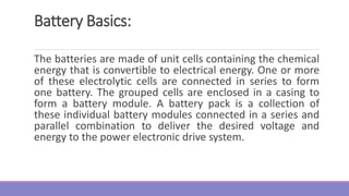
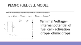
The document provides information on different types of batteries that can be used for electric vehicles (EVs) and hybrid electric vehicles (HEVs). It discusses the basics of lead-acid batteries, nickel-cadmium batteries, nickel-metal hydride batteries, lithium-ion batteries, lithium polymer batteries, sodium-sulfur batteries, and zinc-air batteries. For each battery type, it describes the basic chemistry and reactions that occur during charging and discharging, as well as their advantages and disadvantages for use in EVs and HEVs.

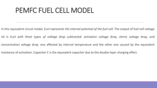
![Battery Basics:
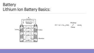
3. Electrolyte: The electrolyte is the medium that permits ionic conduction between positive and
negative electrodes of a cell. The electrolyte must have high and selective conductivity for the ions that
take part in electrode reactions, but it must be a nonconductor for electrons in order to avoid self-
discharge of batteries. The electrolyte may be liquid, gel, or solid material. Also, the electrolyte can be
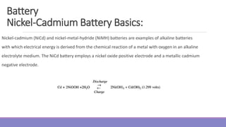
acidic or alkaline, depending on the type of battery. Traditional batteries such as lead-acid and nickel
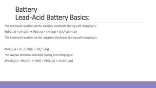
cadmium use liquid electrolytes. In lead-acid batteries, the electrolyte is the aqueous solution of sulfuric
acid [H₂SO (aq)], Advanced batteries currently under development for EVs, such as sealed lead-acid,
nickel metal-hydride (NiMH), and lithium-ion batteries use an electrolyte that is gel, paste, or resin.
Lithium-polymer batteries use a solid electrolyte.
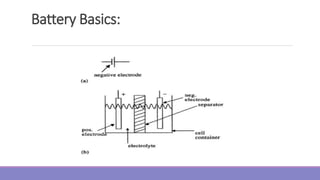
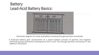
4. Separator: The separator is the electrically insulating layer of material that physically separates
electrodes of opposite polarity. Separators must be permeable to the ions of the electrolyte and may
also have the function of storing or immobilizing the electrolyte. Present day separators are made from
synthetic polymers.](https://image.slidesharecdn.com/evmodule3-240113090728-b98f4a1c/85/ev-module-3-ppt-and-notes-of-EV-to-kno6a-10-320.jpg)


![[NALL OCR] HALL, Basil (1824). Extracts from a journal written on the coasts ...](https://cdn.slidesharecdn.com/ss_thumbnails/nallocrhallbasil1824-260202221936-b93ec330-thumbnail.jpg?width=640&height=640&fit=bounds)


