Download to read offline


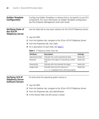


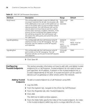


This user guide provides instructions for configuring and maintaining the 3Com VCX IP Telephony Solution components, including the VCX IP Telephony Server, VCX Data Server, XML Accounting Server, SIP Call Processor, IP Messaging System, SIP Phone Downloader, Common Agent, and OS Entity. The guide is intended for operators and administrators and assumes knowledge of telecommunications, VoIP technology, Linux, databases, networking, and system administration. It describes tasks such as installing licenses, backing up configurations, upgrading software, enabling traps, and performing maintenance on the various VCX components.