EMG-Based Prosthetic
Arm ControlUsing
Arduino
Done by :
Adrian Motha
Antony Sebastian
AR Devanandhan
Guided By :
Mr Abhishek Viswakumar
Interim
Presentation(50%)
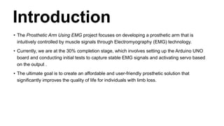
Introduction
• The ProstheticArm Using EMG project focuses on developing a prosthetic arm that is
intuitively controlled by muscle signals through Electromyography (EMG) technology.
• Currently, we are at the 30% completion stage, which involves setting up the Arduino UNO
board and conducting initial tests to capture stable EMG signals and activating servo based
on the output .
• The ultimate goal is to create an affordable and user-friendly prosthetic solution that
significantly improves the quality of life for individuals with limb loss.
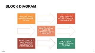
BLOCK DIAGRAM
IMPULSE FROM
HANDUSING EMG
SIGNAL
EMG SENSOR
MODULE TO READ
THE IMPULSE
ANALOG SIGNAL
WILLL BE
TRANSMITTED TO
ARDUINO
SERVO MOTORS
WILL RECIEVE
INSTRUCTION
FROM ARDUINO
PROSTHETIC
HAND IS READY
TO MOVE
3/3/2025 5
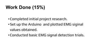
Work Done (15%)
•Completedinitial project research.
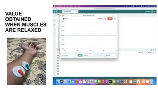
•Set up the Arduino and plotted EMG siginal
values obtained.
•Conducted basic EMG signal detection trials.
8.
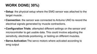
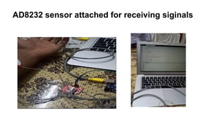
WORK DONE( 30%)
•Setup: the physical setup where the EMG sensor was attached to the
target muscle .
• Connection: the sensor was connected to Arduino UNO to record the
electrical signals generated by muscle contractions.
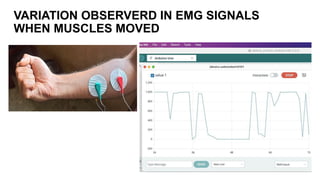
• Configuration Trials: attempted different settings on the sensor and
microcontroller to get usable data. This could involve adjusting the
sensitivity, electrode positioning, or testing on different muscles.
• Servo Activation:The servo motors where activated according to
emg output
9.
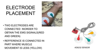
• TWO ELECTRODESARE
CONNECTED INORDER TO
OBTAIN THE EMG SIGINALS(RED
AND GREEN)
• REFFERENCE IS CONNECTED IN
PART WHERE MUSCLE
MOVEMENT IS LESS (YELLOW)
ELECTRODE
PLACEMENT
AD8232 SENSOR
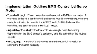
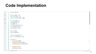
Implementation Outline: EMG-ControlledServo
Motor
• Threshold Logic: The code continuously reads the EMG sensor value. If
the value exceeds a set threshold (indicating muscle contraction), the servo
motor is activated to move to the ACTIVE ANGLE. If it falls below the
threshold, the servo returns to the REST ANGLE.
• Adjustable Threshold: The threshold value might need fine-tuning
depending on the EMG sensor’s sensitivity and the strength of the muscle
signals.
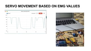
• Debugging: The monitor EMG values in real-time, which is useful for
setting the threshold correctly.
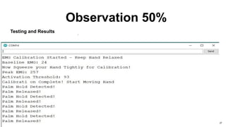
WORK DONE( 50%)
1.EMG Signal Acquisition and Processing
2. Calibration System
3. Servo Motor Control (SG90)
4. Basic Hand Grasping Simulation
3/3/2025 15
16.
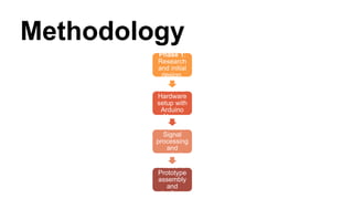
Methodology 50%
1. EMGSensor:Muscle Signal Input: Bioelectrical Acquisition
• The initial stage involves the acquisition of bioelectrical signals through an EMG
sensor.
• This sensor detects the electrical activity generated by muscle contractions,
providing the fundamental input for the prosthetic arm's control.
• Higher muscle contractions produce higher voltage readings, allowing you to
control the arm movements.
• Placement and sensor quality are critical for accurate data collection.
16
17.
Methodology 50%
2. SignalProcessing
• Raw EMG signals are subject to noise and variability, necessitating signal
processing.
• This stage involves signal conditioning, including amplification and filtering,
followed by Exponential Moving Average (EMA) smoothing.
• This process enhances the signal-to-noise ratio, ensuring reliable control.
smoothedEMG = alpha * newReading + (1 - alpha) * smoothedEMG
• alpha: The smoothing factor (0.1)
• newReading: The raw analog value from the EMG sensor.
• smoothedEMG: The stabilized signal value.
17
18.
Methodology 50%
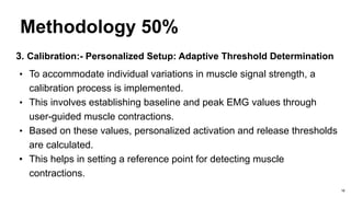
3. Calibration:-Personalized Setup: Adaptive Threshold Determination
• To accommodate individual variations in muscle signal strength, a
calibration process is implemented.
• This involves establishing baseline and peak EMG values through
user-guided muscle contractions.
• Based on these values, personalized activation and release thresholds
are calculated.
• This helps in setting a reference point for detecting muscle
contractions.
18
19.
Methodology 50%
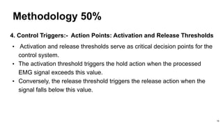
4. ControlTriggers:- Action Points: Activation and Release Thresholds
• Activation and release thresholds serve as critical decision points for the
control system.
• The activation threshold triggers the hold action when the processed
EMG signal exceeds this value.
• Conversely, the release threshold triggers the release action when the
signal falls below this value.
19
20.
Methodology 50%
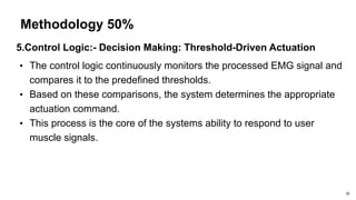
5.Control Logic:-Decision Making: Threshold-Driven Actuation
• The control logic continuously monitors the processed EMG signal and
compares it to the predefined thresholds.
• Based on these comparisons, the system determines the appropriate
actuation command.
• This process is the core of the systems ability to respond to user
muscle signals.
20
21.
Methodology 50%
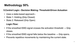
5.Control Logic:-Decision Making: Threshold-Driven Actuation
• Uses a state-based approach:-
• State 1: Holding (Grip Closed)
• State 2: Released (Grip Open)
Logic Flow:
• If the smoothed EMG signal crosses the activation threshold → Grip
closes.
• If the smoothed EMG signal falls below the baseline → Grip opens.
• Prevents repetitive movements by maintaining the current state.
21
22.
Methodology 50%
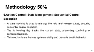
6.Action Control:-StateManagement: Sequential Control
Execution
• A state machine is used to manage the hold and release states, ensuring
sequential control execution.
• The is Holding flag tracks the current state, preventing conflicting or
concurrent actions.
• This mechanism enhances system stability and prevents erratic behavior.
22
23.
Methodology 50%
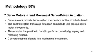
7.Servo Motors:-HandMovement Servo-Driven Actuation
• Servo motors provide the actuation mechanism for the prosthetic hand.
• The control system translates actuation commands into precise servo
motor movements.
• This enables the prosthetic hand to perform controlled grasping and
releasing actions.
• Convert electrical signals into mechanical movement.
23
24.
Methodology
24
Lorem 1
Lorem ipsumdolor sit
amet, consectetur
adipiscing elit. Duis sit
amet odio vel purus
bibendum luctus.
Morbi iaculis dapibus
tristique. In hac nec
habitasse platea
ipsum
dictumst. Mauris nec
convallis quam dolor
at. Morbi iaculis nec
dolor lorem dapibus.
Lorem 2
Lorem ipsum dolor sit
amet, consectetur
adipiscing elit. Duis sit
amet odio vel purus
bibendum luctus.
Morbi iaculis dapibus
tristique. In hac nec
habitasse platea
ipsum
dictumst. Mauris nec
convallis quam dolor
at. Morbi iaculis nec
dolor lorem dapibus.
Lorem 3
Lorem ipsum dolor sit
amet, consectetur
adipiscing elit. Duis sit
amet odio vel purus
bibendum luctus.
Morbi iaculis dapibus
tristique. In hac nec
habitasse platea
ipsum
dictumst. Mauris nec
convallis quam dolor
at. Morbi iaculis nec
dolor lorem dapibus.
Lorem 5
Lorem ipsum dolor sit
amet, consectetur
adipiscing elit. Duis sit
amet odio vel purus
bibendum luctus.
Morbi iaculis dapibus
tristique. In hac nec
habitasse platea
ipsum
dictumst. Mauris nec
convallis quam dolor
at. Morbi iaculis nec
dolor lorem dapibus.
Lorem 4
Lorem ipsum dolor sit
amet, consectetur
adipiscing elit. Duis sit
amet odio vel purus
bibendum luctus.
Morbi iaculis dapibus
tristique. In hac nec
habitasse platea
ipsum
dictumst. Mauris nec
convallis quam dolor
at. Morbi iaculis nec
dolor lorem dapibus.
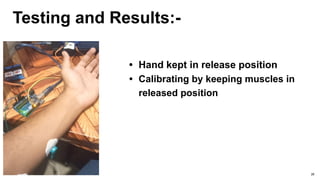
Testing and Results:-
•Hand kept in release position
• Calibrating by keeping muscles in
released position
28
29.
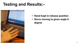
Testing and Results:-
•Hand kept in release position
• Servo moving to given angle 0
degree
29
30.
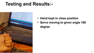
Testing and Results:-
•Hand kept in close position
• Servo moving to given angle 180
degree
30
31.
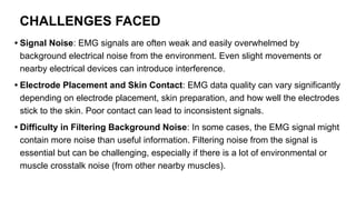
CHALLENGES FACED
• SignalNoise: EMG signals are often weak and easily overwhelmed by
background electrical noise from the environment. Even slight movements or
nearby electrical devices can introduce interference.
• Electrode Placement and Skin Contact: EMG data quality can vary significantly
depending on electrode placement, skin preparation, and how well the electrodes
stick to the skin. Poor contact can lead to inconsistent signals.
• Difficulty in Filtering Background Noise: In some cases, the EMG signal might
contain more noise than useful information. Filtering noise from the signal is
essential but can be challenging, especially if there is a lot of environmental or
muscle crosstalk noise (from other nearby muscles).
32.
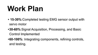
Work Plan
• 15-30%:Completedtesting EMG sensor output with
servo motor
•30-60%:Signal Acquisition, Processing, and Basic
Control Implemented
•60-100%: Integrating components, refining controls,
and testing.
33.
MONTHLY WORK PLAN
•SEPTEMPER 2024 OCTOBER 2024 NOVEMBER 2024 JANUARY 2025 FEBERUARY 2025 MARCH
2025
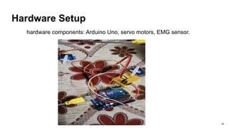
DESIGN OVERVIEW
EMG SIGNAL
PLOTTING WITH
EXTERNAL DATA SET
TESTING EMG
SIGINALS WITH
SERVO MOTOR
BUILDING
MECHANICAL
ARM
INTERGRATING
COMPONENTS
TESTING AND
REFINENING
CONTROLS
34.
Work Division
WORK DONETEAM MEMBER
Hardware Assembly ANTONY SEBASTIAN
Software Development ADRIAN MOTHA
Testing and Calibration
DEVANANDHAN
35.
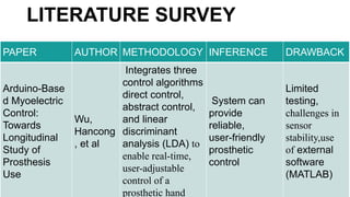
LITERATURE SURVEY
PAPER AUTHORMETHODOLOGY INFERENCE DRAWBACK
Arduino-Base
d Myoelectric
Control:
Towards
Longitudinal
Study of
Prosthesis
Use
Wu,
Hancong
, et al
Integrates three
control algorithms
direct control,
abstract control,
and linear
discriminant
analysis (LDA) to
enable real-time,
user-adjustable
control of a
prosthetic hand
System can
provide
reliable,
user-friendly
prosthetic
control
Limited
testing,
challenges in
sensor
stability,use
of external
software
(MATLAB)
36.
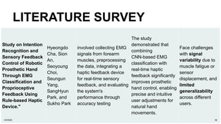
LITERATURE SURVEY
Study onIntention
Recognition and
Sensory Feedback
Control of Robotic
Prosthetic Hand
Through EMG
Classification and
Proprioceptive
Feedback Using
Rule-based Haptic
Device."
Hyeongdo
Cha, Sion
An,
Seoyoung
Choi,
Seungun
Yang,
SangHyun
Park, and
Sukho Park
involved collecting EMG
signals from forearm
muscles, preprocessing
the data, integrating a
haptic feedback device
for real-time sensory
feedback, and evaluating
the system's
performance through
accuracy testing
The study
demonstrated that
combining
CNN-based EMG
classification with
real-time haptic
feedback significantly
improves prosthetic
hand control, enabling
precise and intuitive
user adjustments for
natural hand
movements.
Face challenges
with signal
variability due to
muscle fatigue or
sensor
displacement, and
limited
generalizability
across different
users.
3/3/2025 36
37.
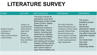
LITERATURE SURVEY
PAPER AUTHORMETHODOLOGY INFERENCE DRAWBACK
Human-Centered
Evaluation of
EMG-Based
Upper-Limb Prosthetic
Control Modes
Yunmei Liu,
Joseph Berman,
Albert Dodson,
Junho Park,
Maryam
Zahabi, He
Huang, Jaime
Ruiz, and David
B. Kaber.
The study involved 36
participants using three
EMG-based control modes
(Direct Control, Pattern
Recognition, and
Continuous Control) to
perform tasks. Various
metrics, including task
performance, cognitive
workload, and usability,
were measured using
eye-tracking and surveys.
Analysis of these metrics
assessed the impact of
each control mode on
upper-limb prosthetic use.
The study found that
Pattern Recognition and
Continuous Control modes
generally offered better
task performance and
lower cognitive load than
Direct Control, especially
in tasks requiring precise
angle adjustments.
The study's
limitations include
the use of
able-bodied
participants instead
of amputees, which
may affect real-world
application insights,
and a
non-randomized
task order,
potentially
influencing results.
38.
References
• S. Hasan,et. al., “Wearable Mind Thoughts Controlled Open Source 3D Printed Arm with
Embedded Sensor Feedback System”, CHIRA 2018 - 2nd International Conference on
Computer-Human Interaction Research and Applications, 2018.
• Ivan I. Borisov et. al., “Prototyping of EMG — Controlled Prosthetic Hand with Sensory
System”, IFAC-Papers OnLine, Elsevier, Volume 50, Issue 1, 2017, pp. 16027-16031. S.
Sudharshan et. Al
• ., “Design and Development of EMG Controlled Prosthetics Limb”, Procedia Engineering,
Elsevier, Vol. 38, 2012, pp. 3547 — 3551. Linda Resnik et. Al.
• “Evaluation of EMG pattern recognition for upper limb prosthesis control: a case study in
comparison with direct myoelectric control”, Journal of NeuroEngineering and
Rehabilitation, Vol. 15, No. 23, 2018.
• Ke Xu et. al., “A prosthetic arm based on EMG pattern recognition”, IEEE International
Conference on Robotics and Biomimetics, 2016.