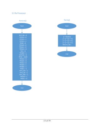
______________________________________________________________________________
-1 of 19-
University of Manitoba
ECE 3730: Principles of Embedded System Design
Assignment 08
Developed by
Chukwuemeka Emeto: 7691553
Bu Aishah Ahmed : 7679633
Ishan Soni: 7706295
______________________________________________________________________________
-2 of 19-
March 30, 2016
Contents
1 Introduction.................................................................................................................................. 3
1.1 Contribution........................................................................................................................................3
2 Wiring Diagram ........................................................................................................................... 4
3 Flow Charts.................................................................................................................................. 7
3.1 Noise injection, Throughput Calculation and LCD Display..................................................................7
3.2 Tx Processor......................................................................................................................................10
3.3 Rx Processor......................................................................................................................................13
4 Test Plan and Procedure............................................................................................................. 16
4.1 Introduction ......................................................................................................................................16
4.2 Items to be Tested/Not Tested.........................................................................................................16
4.3 Procedure..........................................................................................................................................17
5 Video.......................................................................................................................................... 18
6 Design Considerations ............................................................................................................... 18
7 Conclusion ................................................................................................................................. 19
References..................................................................................................................................... 19
______________________________________________________________________________
-3 of 19-
1 Introduction
This report includes two major parts of which one major part involves the design of a system
capable of sending data from one PIC16F877A microcontroller to another via a FIFO. The
second part involves the system detecting a single bit error using parity check. In the event of an
error, the receiver microcontroller sends a retransmit command to the sender microcontroller and
this increases the error count. In situations like this, there is hardly ever any error and this is why
a bit error injector was used to inject errors. Each time the probability of an error is increased on
the bit injector, the receiver sends a retransmit to the sender and the error count increases.
Making the probability of error zero from the bit injector stops the error count and the retransmit
from increasing further.
1.1 Contribution
Chukwuemeka Emeto built the circuit and contributed in writing and editing/trouble shooting
some parts of the code as well as creating some of the required flow charts and compiling the
report. Ahmed Bu Aishah equally contributed in building, writing and editing/trouble shooting
some parts of the code as well as contributing to compile the report. Ishan Soni contributed in
making most of the required flow charts and also helped in compiling the report for the
assignment.
The design challenge was achieved by following Professor Ferens notes and Paul white’s
presentation and explanation on how to go about doing the assignment. The receiver and sender
part of the circuit were built separately and tested individually before finally testing both of them
with the bit injector circuit to ensure all the requirements of the project were met.
______________________________________________________________________________
-4 of 19-
2 Wiring Diagram
Sender Connection
N/B: Pins 9 – 13 and 16-19 of the FIFO aren’t used for the sender connection
Receives noise
injection
Parity bit of
sender
______________________________________________________________________________
-5 of 19-
Receiver Connection
N/B: Pins 1-7 and 24-27 of the FIFO aren’t used for the receiver connection
Parity bit of
receiver
______________________________________________________________________________
-6 of 19-
Noise Connections
Noise injection
source
______________________________________________________________________________
-7 of 19-
3 Flow Charts
3.1 Noise injection, Throughput Calculation and LCD Display
The Data rates for both the receiver and sender are the same in this project and the major reason
for this is that both clock cycles in the receiver and sender were adjusted to give the same data
rates.
Receiver throughput = 5120
Sender through put = 5120
Start
ADCON0 = 0b01000001
ADCON1 = 0b10001110
End
ATDInit(void)
Start
Start A/D Conversion
ADCON0bits.GO_DONE
= 1
While(ADCON0bits.GO_DONE = 1) Return(u8)ADRESL
End
Y
N
getADC(void)
______________________________________________________________________________
-8 of 19-
Start
u32 randonCounter = 0
u16 prob[11] = [values…..]
If(TMR2IF == True)
Ra4 = 1 (Remove bit error)
milliSecondCounter++
randonCounter++
If (randomCounter == 500)
RA5 = !RA5
randomCounter = 0
if(myRandomNumber >
prob[value])
errorCount++
RA4 = 0
TMR2IF = False
If(INTF == True)
If (clockwise)
If (value == TOP_LIMIT)
Value = 0
Value++ If(value == 0)
Value--
Value = TOP_LIMIT
IMTF = False
End
Return
myInterruptFunction()
Y
Y
Y
Y
Y Y
N
N
N
N
N
Y
N
______________________________________________________________________________
-9 of 19-
Start
U32 secoundsCounter = 0
u8 seed = 0
char string1[20]
portInit()
LCDInit()
ATDInit()
seed = getADC()
srand(seed)
timer2Init()
While(1)
myRandomNumber = rand()
if(milliSecondsCounter >= 1000)
secondsCounter++
milliSecondsCounter = 0
sprintf(string1, "T:%lu P:%u%%",secondsCounter, 10*value)
clearDisplay()
setDisplayLine(1, 0)
writeString(string1)
sprintf(string1, "E:%lu", errorCount)
setDisplayLine(2, 0)
writeString(string1)
End
Main
Y
Y
N
______________________________________________________________________________
-10 of 19-
3.2 Tx Processor
Fifo init()
Start
1 = Disable
0 = Enable
Fifo Write = 1
Fifo read = 1
Fifo reset = 0
Fifo reset = 1
End
Fifo write ()
Start
While (Fifo_NOT_Full)
PORTC = i++
Enable Write = 0
Disable Write = 1
End
N
Y
Fifo write ()
Start
While (Fifo_NOT_Full)
PORTC = i++
Enable Write = 0
Disable Write = 1
End
N
Y
______________________________________________________________________________
-11 of 19-
Start
INTCON = 0
PCFG3 = 0
PCFG2 = 1
PCFG1 = 1
TRISD = 0
TRISA0 = 0
TRISA1 = 0
TRISA2 = 0
RA2 = 0
TRISB0 = 1
INTEDG = 0
TRISC = 0x00
TRISA3 = 0
TRISA5 = 0
TRISE2 = 0
TRISE0 = 1
TRISB0 = 1
TRISE1 = 1
FIFO_Wn = 1
FIFO_Rn = 1
FIFO_RSn = 1
TRISA4 = 0
TRISE1 = 1
End
Portinit()
Start
p = theData
p = p ^ (p >> 4)
p = p ^ (p >> 2)
p = p ^ (p >> 1)
Return p & 1
End
Parity()
______________________________________________________________________________
-12 of 19-
Start
If INTF == 1
FIFO_Wn = 0;
FIFO_Rn = 1;
While (FIFO_NOT_FULL)
FIFO_D = i++
calcparity = Call function [Parity(FIFO_D)]
RA4 = calcparity;
FIFO_Wn = 0;
FIFO_Wn = 1
count++;
INTF = 0
If TMR2IF == 1
oneSecondCounter++
TMR2IF = 0
End
Y
Y
Y
N
N
N
myISR()
Start
portInit()
LCDInit()
FIFOReset()
timer2Init()
setDisplayLine(1, 0)
writeString("Throughput=")
setDisplayLine(2, 0)
writeString("RTnumber =");
Enable Interrupts
INTF = 0
TMR2IF = 0
INTE = 1
TMR2IE = 1
PEIE = 1
GIE = 1
delay(200)
INTF = 1;
While(1)
If (RE1 ==1)
retrans++
FIFOReset()
INTF = 1
If (oneSecondCounter == 19
ltoa(myNum, count, 10)
setDisplayLine(1, 11)
writeString(myNum)
ltoa(myNum, retrans, 10)
setDisplayLine(2, 11)
writeString(myNum)
prevCount = count
count = 0
oneSecondCounter = 0
End
Y
Y
N
N
main
______________________________________________________________________________
-13 of 19-
3.3 Rx Processor
Start
INTCON = 0
PCFG3 = 0
PCFG2 = 1
PCFG1 = 1
TRISD = 0
TRISA0 = 0
TRISA1 = 0
TRISA2 = 0
RA2 = 0
TRISB0 = 1
INTEDG = 0
TRISC = 0x00
TRISA3 = 0
TRISA5 = 0
TRISE2 = 0
TRISE0 = 1
TRISB0 = 1
TRISE1 = 1
FIFO_Wn = 1
FIFO_Rn = 1
FIFO_RSn = 1
TRISA4 = 1
TRISE1 = 0
End
Portinit()
Start
p = theData
p = p ^ (p >> 4)
p = p ^ (p >> 2)
p = p ^ (p >> 1)
Return p & 1
End
Parity()
______________________________________________________________________________
-14 of 19-
Start
portInit()
LCDInit()
FIFOReset()
timer2Init()
setDisplayLine(1, 0)
writeString("Throughput=")
setDisplayLine(2, 0)
writeString("errorCount =")
Enable Interrupts
INTF = 0
TMR2IF = 0
INTE = 1
TMR2IE = 1
PEIE = 1
GIE = 1
While(1)
If (smellinguy ==1)
RE = 1
Smellinguy = 0
If (oneSecondCounter == 19
ltoa(myNum, count, 10)
setDisplayLine(1, 11)
writeString(myNum)
ltoa(myNum, retrans, 10)
setDisplayLine(2, 11)
writeString(myNum)
prevCount = count
count = 0
oneSecondCounter = 0
End
Y
Y
N
N
main
Start
Fifo read
While(Fifo Not Empty)
Enable Read
Fifo_Rn = 0
Dummy = PORTC
Disable Read
Fifo_Rn = 1
END
______________________________________________________________________________
-15 of 19-
Start
If INTF == 1
If F IFO_NOT_EMPTY
While (FIF O_NOT_EMPTY)
FIF O_Rn = 1
Dummy = FIF O_Q
If(dummy !=
expectedValue++)
errorCount++
smellingguy = 1
storeparity = RA4
calcparity = Parity(dummy);
If(calcparity != storeparity)
errorCount++
smellingguy = 1
FIF O_Rn = 1
If (smellinguy ==1)
RE1 = 0
Count+= 256
INTF = 0
If TMR2IF == 1
oneSecondCounter++
TM R2IF = 0
End
myISR()
Y
Y
Y
Y
Y
Y
Y
N
N
N
N
N
N N
______________________________________________________________________________
-16 of 19-
4 Test Plan and Procedure
4.1 Introduction
The Test plan and Procedure successfully explains in detail the different items that were tested in
this project and how the tests were carried out as well as when and who tested these different
items. The procedure also helps understand in detail how to run the project and test it to make
sure it meets the specific requirements.
4.2 Items to be Tested/Not Tested
Item to Test Test Description Date Responsible
Receiving of data
From FIFO using
the desired
PIC16F877A
Displaying data on
LCD for receiver
circuit
Run the desired code for the
Receiver circuit so as to
prepare the circuit to read
from a FIFO using the desired
microcontroller(PIC16F877A)
Run the desired code for the
Receiver circuit and this
should show the throughput
22 March 2016
22 March 2016
Chukwuemeka
Emeto, Ahmed Bu
Aishah
Chukwuemeka
Emeto
Transmission
of data be-
tween two
PIC16F877A
Displaying data on
LCD for receiver
circuit
Parity Function
Error Injector
Run the desired code for the
Sender circuit, this now sends
data to the receiver circuit,
recall that the receiver circuit
has already been prepared,
therefore the receiver circuit
now receives the sent data
from the sender
Run the desired code for the
sender circuit and this should
successfully display the
throughput value
Run the modified sender and
receiver code that includes the
parity, this should calculate
the required parity
Run the modified sender and
receiver circuit with the error
bit injector connected,
22 March 2016
22 March 2016
31 March 2016
31 March 2016
Chukwuemeka
Emeto, Ahmed Bu
Aishah
Chukwuemeka
Emeto, Ahmed Bu
Aishah
Chukwuemeka
Emeto, Ahmed Bu
Aishah
Chukwuemeka
Emeto, Ahmed Bu
Aishah
______________________________________________________________________________
-17 of 19-
Retransmitting
Throughput value
increasing the probability of
the error should successfully
increase the error count on the
Receiver
Run the modified sender and
receiver circuit with the error
injector, a retransmit signal
should be sent each time a
wrong packet is detected
Running the modified sender
code and the receiver code
should reduce the throughput
value by one quarter
31 March, 2016
31 March, 2016
Chukwuemeka
Emeto, Ahmed Bu
Aishah
Chukwuemeka
Emeto, Ahmed Bu
Aisha
4.3 Procedure
Instruction Pass/Fail
1 Connect the board and design the circuit as shown in the schematic P
2 Connect the board to a PC and open the MPLAB X IDE P
3 Open the required codes for both the sender and receiver circuit P
4 Debug each code respectively to ensure there are no errors P
5 Run the code for the receiver circuit with the board connected to the
receiver circuit alone
P
6 Should successfully display “throughput” on the LCD P
7 Run the code for the sender circuit with the board connected to the
sender circuit alone
P
8 Should successfully display the throughput value that is being sent on
the LCD of the sender as well the throughput value being received on
the LCD of the receiver.
P
9 Modify the previous receiver and sender code to check for parity and
each time a retransmission occurs. Debug the code when done to ensure
there are no errors
P
10 Build the required Bit injector circuit as showed on the schematic and
test the circuit by turning the rotary switch and this should increase the
error probability
P
11 Connect the Bit injector as a source of noise to the receiver circuit P
12 Assign RE1(retransmit pin) as an output for the receiver and an input for
the transmitter
P
13 Connect the parity pins of the receiver and the sender circuit P
14 Run the sender and receiver code with the bit injector probability set to
zero and this should give you a throughput value that is the same for
both the receiver and sender as well as an error and a retransmit of zero
P
______________________________________________________________________________
-18 of 19-
15 Increase the error probability and this should decrease the throughput of
the receiver as well as increase the retransmit and the error count
P
16 Set the error probability back to zero, this should stop the retransmit and
the error count
P
5 Video
A drop box link to the video is attached below
https://www.dropbox.com/s/pufssgrb7qqlg1g/Project%205%20video.MOV?dl=0
6 Design Considerations
1. For this project, the class of noise being considered are random single errors
2. The noise is generated from an open drain of a PN junction instead of a synthetic noise by
another microcontroller because that of a microcontroller is very predictable whereas, that of a
PN junction is very random and cannot be predicted. The main advantage of using the PN
junction is due to its random nature and the disadvantage of that from a microcontroller is the
predictability nature of the noise.
3. An Automatic repeat request (ARQ) error correction is being considered for this project
4. For this project, the parity function is using the XOR logic gate for the first two bites, then the
answer is used for the next bite, and this goes on till the last bite and finally returns a zero or a
one. If a one is being returned, the least significant bit equals a one and it senses an error else, the
least significant bit equals a zero. One limitation of using parity bits as error detectors is that they
cannot detect all form of errors.
5. The control panel should be between the Rx and Tx because these gives more options when it
comes to receiving and sending data.
6. The throughput counter is incremented for every clock cycle and for every byte and the
throughput itself is calculated for every byte. This is done in this manner to give a more stable
and accurate value of the throughput. The throughput is displayed and updated on the LCD and
this is done every one second. The above factors do not affect the throughput itself because the
throughput is updated immediately after it displays and this happens continuously till there is no
more voltage supply to the circuit.
______________________________________________________________________________
-19 of 19-
7. The throughput compromises for no noise by sending bigger packets than it did previously and
this is how it is maximized. The throughput is optimized by sending smaller packets when there
is no noise. One factor affecting the different times is adjusting the clock cycle of the micro
controller, this will definitely increase or decrease the packet transmission time depending on
how the clock cycle is being adjusted. The throughput will definitely take longer to send the
smaller packets than the bigger ones because there are more smaller packets than they are bigger
ones. Getting an error will also increase the time it takes for transmission. A size of a packet
should be 256 and should have a 9-bit word. The packet size is also shorter when the noise level
increases because there are more errors and this causes lesser packet size. The packet size is
longer when the noise level decreases because there are less errors and therefore more good
packets.
7 Conclusion
After successfully building the required sender, receiver and bit injector error circuit with each
respective LCD, writing the code for the sender and receiver and using the given code for the bit
injector error circuit, debugging the code and finally implementing and running the code through
the MPLAB X IDE, the receiver circuit successfully received its respective information from the
sender and they both had the same throughput value which was one requirement of the project,
the receiver also detected errors from the bit injector when the probability was increased which
was another requirement of the project, a retransmit signal was sent from the receiver to the
sender each time the receiver received a bad byte, also another requirement of the project, and
finally, increasing the error probability increased the error count and the number of signals being
retransmitted while taking the error probability stopped the retransmit signal and the error count.
Therefore, all the requirements for the project were met.
References
[1].W. Kinsner, ECE4240 Microprocessor Interfacing For Real Time Systems, Final Lab Report
Guide (2014)
[2]. W. Kinsner, ECE3730 PRINCIPLES OF EMBEDDED SYSTEMS DESIGN, Project 4
manual, Dual-Microcontroller FIFO Data Transfer with Emulated Random Noise Injected into
the Data Channel, ECE3730Project4Mv311.pdf

Emeto_Chukwuemeka_7691553_A8

  • 1.
    ______________________________________________________________________________ -1 of 19- Universityof Manitoba ECE 3730: Principles of Embedded System Design Assignment 08 Developed by Chukwuemeka Emeto: 7691553 Bu Aishah Ahmed : 7679633 Ishan Soni: 7706295
  • 2.
    ______________________________________________________________________________ -2 of 19- March30, 2016 Contents 1 Introduction.................................................................................................................................. 3 1.1 Contribution........................................................................................................................................3 2 Wiring Diagram ........................................................................................................................... 4 3 Flow Charts.................................................................................................................................. 7 3.1 Noise injection, Throughput Calculation and LCD Display..................................................................7 3.2 Tx Processor......................................................................................................................................10 3.3 Rx Processor......................................................................................................................................13 4 Test Plan and Procedure............................................................................................................. 16 4.1 Introduction ......................................................................................................................................16 4.2 Items to be Tested/Not Tested.........................................................................................................16 4.3 Procedure..........................................................................................................................................17 5 Video.......................................................................................................................................... 18 6 Design Considerations ............................................................................................................... 18 7 Conclusion ................................................................................................................................. 19 References..................................................................................................................................... 19
  • 3.
    ______________________________________________________________________________ -3 of 19- 1Introduction This report includes two major parts of which one major part involves the design of a system capable of sending data from one PIC16F877A microcontroller to another via a FIFO. The second part involves the system detecting a single bit error using parity check. In the event of an error, the receiver microcontroller sends a retransmit command to the sender microcontroller and this increases the error count. In situations like this, there is hardly ever any error and this is why a bit error injector was used to inject errors. Each time the probability of an error is increased on the bit injector, the receiver sends a retransmit to the sender and the error count increases. Making the probability of error zero from the bit injector stops the error count and the retransmit from increasing further. 1.1 Contribution Chukwuemeka Emeto built the circuit and contributed in writing and editing/trouble shooting some parts of the code as well as creating some of the required flow charts and compiling the report. Ahmed Bu Aishah equally contributed in building, writing and editing/trouble shooting some parts of the code as well as contributing to compile the report. Ishan Soni contributed in making most of the required flow charts and also helped in compiling the report for the assignment. The design challenge was achieved by following Professor Ferens notes and Paul white’s presentation and explanation on how to go about doing the assignment. The receiver and sender part of the circuit were built separately and tested individually before finally testing both of them with the bit injector circuit to ensure all the requirements of the project were met.
  • 4.
    ______________________________________________________________________________ -4 of 19- 2Wiring Diagram Sender Connection N/B: Pins 9 – 13 and 16-19 of the FIFO aren’t used for the sender connection Receives noise injection Parity bit of sender
  • 5.
    ______________________________________________________________________________ -5 of 19- ReceiverConnection N/B: Pins 1-7 and 24-27 of the FIFO aren’t used for the receiver connection Parity bit of receiver
  • 6.
  • 7.
    ______________________________________________________________________________ -7 of 19- 3Flow Charts 3.1 Noise injection, Throughput Calculation and LCD Display The Data rates for both the receiver and sender are the same in this project and the major reason for this is that both clock cycles in the receiver and sender were adjusted to give the same data rates. Receiver throughput = 5120 Sender through put = 5120 Start ADCON0 = 0b01000001 ADCON1 = 0b10001110 End ATDInit(void) Start Start A/D Conversion ADCON0bits.GO_DONE = 1 While(ADCON0bits.GO_DONE = 1) Return(u8)ADRESL End Y N getADC(void)
  • 8.
    ______________________________________________________________________________ -8 of 19- Start u32randonCounter = 0 u16 prob[11] = [values…..] If(TMR2IF == True) Ra4 = 1 (Remove bit error) milliSecondCounter++ randonCounter++ If (randomCounter == 500) RA5 = !RA5 randomCounter = 0 if(myRandomNumber > prob[value]) errorCount++ RA4 = 0 TMR2IF = False If(INTF == True) If (clockwise) If (value == TOP_LIMIT) Value = 0 Value++ If(value == 0) Value-- Value = TOP_LIMIT IMTF = False End Return myInterruptFunction() Y Y Y Y Y Y N N N N N Y N
  • 9.
    ______________________________________________________________________________ -9 of 19- Start U32secoundsCounter = 0 u8 seed = 0 char string1[20] portInit() LCDInit() ATDInit() seed = getADC() srand(seed) timer2Init() While(1) myRandomNumber = rand() if(milliSecondsCounter >= 1000) secondsCounter++ milliSecondsCounter = 0 sprintf(string1, "T:%lu P:%u%%",secondsCounter, 10*value) clearDisplay() setDisplayLine(1, 0) writeString(string1) sprintf(string1, "E:%lu", errorCount) setDisplayLine(2, 0) writeString(string1) End Main Y Y N
  • 10.
    ______________________________________________________________________________ -10 of 19- 3.2Tx Processor Fifo init() Start 1 = Disable 0 = Enable Fifo Write = 1 Fifo read = 1 Fifo reset = 0 Fifo reset = 1 End Fifo write () Start While (Fifo_NOT_Full) PORTC = i++ Enable Write = 0 Disable Write = 1 End N Y Fifo write () Start While (Fifo_NOT_Full) PORTC = i++ Enable Write = 0 Disable Write = 1 End N Y
  • 11.
    ______________________________________________________________________________ -11 of 19- Start INTCON= 0 PCFG3 = 0 PCFG2 = 1 PCFG1 = 1 TRISD = 0 TRISA0 = 0 TRISA1 = 0 TRISA2 = 0 RA2 = 0 TRISB0 = 1 INTEDG = 0 TRISC = 0x00 TRISA3 = 0 TRISA5 = 0 TRISE2 = 0 TRISE0 = 1 TRISB0 = 1 TRISE1 = 1 FIFO_Wn = 1 FIFO_Rn = 1 FIFO_RSn = 1 TRISA4 = 0 TRISE1 = 1 End Portinit() Start p = theData p = p ^ (p >> 4) p = p ^ (p >> 2) p = p ^ (p >> 1) Return p & 1 End Parity()
  • 12.
    ______________________________________________________________________________ -12 of 19- Start IfINTF == 1 FIFO_Wn = 0; FIFO_Rn = 1; While (FIFO_NOT_FULL) FIFO_D = i++ calcparity = Call function [Parity(FIFO_D)] RA4 = calcparity; FIFO_Wn = 0; FIFO_Wn = 1 count++; INTF = 0 If TMR2IF == 1 oneSecondCounter++ TMR2IF = 0 End Y Y Y N N N myISR() Start portInit() LCDInit() FIFOReset() timer2Init() setDisplayLine(1, 0) writeString("Throughput=") setDisplayLine(2, 0) writeString("RTnumber ="); Enable Interrupts INTF = 0 TMR2IF = 0 INTE = 1 TMR2IE = 1 PEIE = 1 GIE = 1 delay(200) INTF = 1; While(1) If (RE1 ==1) retrans++ FIFOReset() INTF = 1 If (oneSecondCounter == 19 ltoa(myNum, count, 10) setDisplayLine(1, 11) writeString(myNum) ltoa(myNum, retrans, 10) setDisplayLine(2, 11) writeString(myNum) prevCount = count count = 0 oneSecondCounter = 0 End Y Y N N main
  • 13.
    ______________________________________________________________________________ -13 of 19- 3.3Rx Processor Start INTCON = 0 PCFG3 = 0 PCFG2 = 1 PCFG1 = 1 TRISD = 0 TRISA0 = 0 TRISA1 = 0 TRISA2 = 0 RA2 = 0 TRISB0 = 1 INTEDG = 0 TRISC = 0x00 TRISA3 = 0 TRISA5 = 0 TRISE2 = 0 TRISE0 = 1 TRISB0 = 1 TRISE1 = 1 FIFO_Wn = 1 FIFO_Rn = 1 FIFO_RSn = 1 TRISA4 = 1 TRISE1 = 0 End Portinit() Start p = theData p = p ^ (p >> 4) p = p ^ (p >> 2) p = p ^ (p >> 1) Return p & 1 End Parity()
  • 14.
    ______________________________________________________________________________ -14 of 19- Start portInit() LCDInit() FIFOReset() timer2Init() setDisplayLine(1,0) writeString("Throughput=") setDisplayLine(2, 0) writeString("errorCount =") Enable Interrupts INTF = 0 TMR2IF = 0 INTE = 1 TMR2IE = 1 PEIE = 1 GIE = 1 While(1) If (smellinguy ==1) RE = 1 Smellinguy = 0 If (oneSecondCounter == 19 ltoa(myNum, count, 10) setDisplayLine(1, 11) writeString(myNum) ltoa(myNum, retrans, 10) setDisplayLine(2, 11) writeString(myNum) prevCount = count count = 0 oneSecondCounter = 0 End Y Y N N main Start Fifo read While(Fifo Not Empty) Enable Read Fifo_Rn = 0 Dummy = PORTC Disable Read Fifo_Rn = 1 END
  • 15.
    ______________________________________________________________________________ -15 of 19- Start IfINTF == 1 If F IFO_NOT_EMPTY While (FIF O_NOT_EMPTY) FIF O_Rn = 1 Dummy = FIF O_Q If(dummy != expectedValue++) errorCount++ smellingguy = 1 storeparity = RA4 calcparity = Parity(dummy); If(calcparity != storeparity) errorCount++ smellingguy = 1 FIF O_Rn = 1 If (smellinguy ==1) RE1 = 0 Count+= 256 INTF = 0 If TMR2IF == 1 oneSecondCounter++ TM R2IF = 0 End myISR() Y Y Y Y Y Y Y N N N N N N N
  • 16.
    ______________________________________________________________________________ -16 of 19- 4Test Plan and Procedure 4.1 Introduction The Test plan and Procedure successfully explains in detail the different items that were tested in this project and how the tests were carried out as well as when and who tested these different items. The procedure also helps understand in detail how to run the project and test it to make sure it meets the specific requirements. 4.2 Items to be Tested/Not Tested Item to Test Test Description Date Responsible Receiving of data From FIFO using the desired PIC16F877A Displaying data on LCD for receiver circuit Run the desired code for the Receiver circuit so as to prepare the circuit to read from a FIFO using the desired microcontroller(PIC16F877A) Run the desired code for the Receiver circuit and this should show the throughput 22 March 2016 22 March 2016 Chukwuemeka Emeto, Ahmed Bu Aishah Chukwuemeka Emeto Transmission of data be- tween two PIC16F877A Displaying data on LCD for receiver circuit Parity Function Error Injector Run the desired code for the Sender circuit, this now sends data to the receiver circuit, recall that the receiver circuit has already been prepared, therefore the receiver circuit now receives the sent data from the sender Run the desired code for the sender circuit and this should successfully display the throughput value Run the modified sender and receiver code that includes the parity, this should calculate the required parity Run the modified sender and receiver circuit with the error bit injector connected, 22 March 2016 22 March 2016 31 March 2016 31 March 2016 Chukwuemeka Emeto, Ahmed Bu Aishah Chukwuemeka Emeto, Ahmed Bu Aishah Chukwuemeka Emeto, Ahmed Bu Aishah Chukwuemeka Emeto, Ahmed Bu Aishah
  • 17.
    ______________________________________________________________________________ -17 of 19- Retransmitting Throughputvalue increasing the probability of the error should successfully increase the error count on the Receiver Run the modified sender and receiver circuit with the error injector, a retransmit signal should be sent each time a wrong packet is detected Running the modified sender code and the receiver code should reduce the throughput value by one quarter 31 March, 2016 31 March, 2016 Chukwuemeka Emeto, Ahmed Bu Aishah Chukwuemeka Emeto, Ahmed Bu Aisha 4.3 Procedure Instruction Pass/Fail 1 Connect the board and design the circuit as shown in the schematic P 2 Connect the board to a PC and open the MPLAB X IDE P 3 Open the required codes for both the sender and receiver circuit P 4 Debug each code respectively to ensure there are no errors P 5 Run the code for the receiver circuit with the board connected to the receiver circuit alone P 6 Should successfully display “throughput” on the LCD P 7 Run the code for the sender circuit with the board connected to the sender circuit alone P 8 Should successfully display the throughput value that is being sent on the LCD of the sender as well the throughput value being received on the LCD of the receiver. P 9 Modify the previous receiver and sender code to check for parity and each time a retransmission occurs. Debug the code when done to ensure there are no errors P 10 Build the required Bit injector circuit as showed on the schematic and test the circuit by turning the rotary switch and this should increase the error probability P 11 Connect the Bit injector as a source of noise to the receiver circuit P 12 Assign RE1(retransmit pin) as an output for the receiver and an input for the transmitter P 13 Connect the parity pins of the receiver and the sender circuit P 14 Run the sender and receiver code with the bit injector probability set to zero and this should give you a throughput value that is the same for both the receiver and sender as well as an error and a retransmit of zero P
  • 18.
    ______________________________________________________________________________ -18 of 19- 15Increase the error probability and this should decrease the throughput of the receiver as well as increase the retransmit and the error count P 16 Set the error probability back to zero, this should stop the retransmit and the error count P 5 Video A drop box link to the video is attached below https://www.dropbox.com/s/pufssgrb7qqlg1g/Project%205%20video.MOV?dl=0 6 Design Considerations 1. For this project, the class of noise being considered are random single errors 2. The noise is generated from an open drain of a PN junction instead of a synthetic noise by another microcontroller because that of a microcontroller is very predictable whereas, that of a PN junction is very random and cannot be predicted. The main advantage of using the PN junction is due to its random nature and the disadvantage of that from a microcontroller is the predictability nature of the noise. 3. An Automatic repeat request (ARQ) error correction is being considered for this project 4. For this project, the parity function is using the XOR logic gate for the first two bites, then the answer is used for the next bite, and this goes on till the last bite and finally returns a zero or a one. If a one is being returned, the least significant bit equals a one and it senses an error else, the least significant bit equals a zero. One limitation of using parity bits as error detectors is that they cannot detect all form of errors. 5. The control panel should be between the Rx and Tx because these gives more options when it comes to receiving and sending data. 6. The throughput counter is incremented for every clock cycle and for every byte and the throughput itself is calculated for every byte. This is done in this manner to give a more stable and accurate value of the throughput. The throughput is displayed and updated on the LCD and this is done every one second. The above factors do not affect the throughput itself because the throughput is updated immediately after it displays and this happens continuously till there is no more voltage supply to the circuit.
  • 19.
    ______________________________________________________________________________ -19 of 19- 7.The throughput compromises for no noise by sending bigger packets than it did previously and this is how it is maximized. The throughput is optimized by sending smaller packets when there is no noise. One factor affecting the different times is adjusting the clock cycle of the micro controller, this will definitely increase or decrease the packet transmission time depending on how the clock cycle is being adjusted. The throughput will definitely take longer to send the smaller packets than the bigger ones because there are more smaller packets than they are bigger ones. Getting an error will also increase the time it takes for transmission. A size of a packet should be 256 and should have a 9-bit word. The packet size is also shorter when the noise level increases because there are more errors and this causes lesser packet size. The packet size is longer when the noise level decreases because there are less errors and therefore more good packets. 7 Conclusion After successfully building the required sender, receiver and bit injector error circuit with each respective LCD, writing the code for the sender and receiver and using the given code for the bit injector error circuit, debugging the code and finally implementing and running the code through the MPLAB X IDE, the receiver circuit successfully received its respective information from the sender and they both had the same throughput value which was one requirement of the project, the receiver also detected errors from the bit injector when the probability was increased which was another requirement of the project, a retransmit signal was sent from the receiver to the sender each time the receiver received a bad byte, also another requirement of the project, and finally, increasing the error probability increased the error count and the number of signals being retransmitted while taking the error probability stopped the retransmit signal and the error count. Therefore, all the requirements for the project were met. References [1].W. Kinsner, ECE4240 Microprocessor Interfacing For Real Time Systems, Final Lab Report Guide (2014) [2]. W. Kinsner, ECE3730 PRINCIPLES OF EMBEDDED SYSTEMS DESIGN, Project 4 manual, Dual-Microcontroller FIFO Data Transfer with Emulated Random Noise Injected into the Data Channel, ECE3730Project4Mv311.pdf