Download to read offline


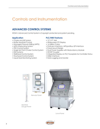


Worldwide Oilfield Machine (WOM) specializes in advanced control systems for the oil and gas industry, providing safety-focused products including choke control systems and emergency shutdown systems. The company emphasizes quality management and compliance with industry standards, ensuring customer satisfaction and continuous improvement. WOM has a global presence with strong infrastructure, allowing for effective management of quality and service delivery.