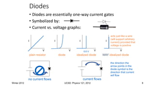
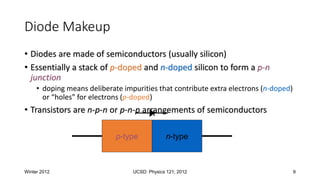
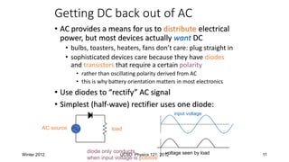
Electronics Overview
Basic Circuits, Power Supplies,
Transistors, Cable Impedance
diode bridge
Winter 2012 UCSD: Physics 121; 2012 3
Basic Circuit Analysis
• What we won’t do:
• common electronics-class things: RLC, filters, detailed analysis
• What we will do:
• set out basic relations
• look at a few examples of fundamental importance (mostly resistive circuits)
• look at diodes, voltage regulation, transistors
• discuss impedances (cable, output, etc.)
Winter 2012 UCSD: Physics 121; 2012 4
The Basic Relations
• V is voltage (volts: V); I is current (amps: A); R is resistance (ohms: );
C is capacitance (farads: F); L is inductance (henrys: H)
• Ohm’s Law: V = IR; V = ; V = L(dI/dt)
• Power: P = IV = V2/R = I2R
• Resistors and inductors in series add
• Capacitors in parallel add
• Resistors and inductors in parallel, and capacitors in series add
according to:
Winter 2012 UCSD: Physics 121; 2012 5
Example: Voltage divider
• Voltage dividers are a classic way to set a
voltage
• Works on the principle that all charge
flowing through the first resistor goes
through the second
• so V  R-value
• provided any load at output is negligible:
otherwise some current goes there too
• So Vout = V(R2/(R1 + R2))
• R2 here is a variable resistor, or
potentiometer, or “pot”
• typically three terminals: R12 is fixed, tap
slides along to vary R13 and R23, though
R13 + R23 = R12 always
1
2
3
R1
R2
V Vout
Winter 2012 UCSD: Physics 121; 2012 6
Real Batteries: Output Impedance
• A power supply (battery) is characterized by a voltage
(V) and an output impedance (R)
• sometimes called source impedance
• Hooking up to load: Rload, we form a voltage divider, so
that the voltage applied by the battery terminal is
actually Vout = V(Rload/(R+Rload))
• thus the smaller R is, the “stiffer” the power supply
• when Vout sags with higher load current, we call this
“droop”
• Example: If 10.0 V power supply droops by 1% (0.1 V)
when loaded to 1 Amp (10  load):
• internal resistance is 0.1 
• called output impedance or source impedance
• may vary with load, though (not a real resistor)
V
R
D-cell example: 6A
out of 1.5 V battery
indicates 0.25  output
impedance
Winter 2012 UCSD: Physics 121; 2012 7
Power Supplies and Regulation
• A power supply typically starts with a transformer
• to knock down the 340 V peak-to-peak (120 V AC) to something
reasonable/manageable
• We will be using a center-tap transformer
• (A’  B’) = (winding ratio)(A  B)
• when A > B, so is A’ > B’
• geometry of center tap (CT) guarantees it is midway between A’ and B’
(frequently tie this to ground so that A’ = B’)
• note that secondary side floats: no ground reference built-in
A
B
A’
CT
B’
AC input AC output
Winter 2012 UCSD: Physics 121; 2012 8
Diodes
• Diodes are essentially one-way current gates
• Symbolized by:
• Current vs. voltage graphs:
V
I
V
I
V
I
V
I
0.6 V
plain resistor diode idealized diode WAY idealized diode
no current flows current flows
the direction the
arrow points in the
diode symbol is the
direction that current
will flow
acts just like a wire
(will support arbitrary
current) provided that
voltage is positive
Winter 2012 UCSD: Physics 121; 2012 9
Diode Makeup
• Diodes are made of semiconductors (usually silicon)
• Essentially a stack of p-doped and n-doped silicon to form a p-n
junction
• doping means deliberate impurities that contribute extra electrons (n-doped)
or “holes” for electrons (p-doped)
• Transistors are n-p-n or p-n-p arrangements of semiconductors
p-type n-type
Winter 2012 UCSD: Physics 121; 2012 10
LEDs: Light-Emitting Diodes
• Main difference is material is more exotic than silicon used in ordinary
diodes/transistors
• typically 2-volt drop instead of 0.6 V drop
• When electron flows through LED, loses energy by emitting a photon of light
rather than vibrating lattice (heat)
• LED efficiency is 30% (compare to incandescent bulb at 10%)
• Must supply current-limiting resistor in series:
• figure on 2 V drop across LED; aim for 1–10 mA of current
Winter 2012 UCSD: Physics 121; 2012 11
Getting DC back out of AC
• AC provides a means for us to distribute electrical
power, but most devices actually want DC
• bulbs, toasters, heaters, fans don’t care: plug straight in
• sophisticated devices care because they have diodes
and transistors that require a certain polarity
• rather than oscillating polarity derived from AC
• this is why battery orientation matters in most electronics
• Use diodes to “rectify” AC signal
• Simplest (half-wave) rectifier uses one diode:
AC source load
input voltage
voltage seen by load
diode only conducts
when input voltage is positive

Electronics_ diode circuits_concept.pptx

  • 2.
    Electronics Overview Basic Circuits,Power Supplies, Transistors, Cable Impedance diode bridge
  • 3.
    Winter 2012 UCSD:Physics 121; 2012 3 Basic Circuit Analysis • What we won’t do: • common electronics-class things: RLC, filters, detailed analysis • What we will do: • set out basic relations • look at a few examples of fundamental importance (mostly resistive circuits) • look at diodes, voltage regulation, transistors • discuss impedances (cable, output, etc.)
  • 4.
    Winter 2012 UCSD:Physics 121; 2012 4 The Basic Relations • V is voltage (volts: V); I is current (amps: A); R is resistance (ohms: ); C is capacitance (farads: F); L is inductance (henrys: H) • Ohm’s Law: V = IR; V = ; V = L(dI/dt) • Power: P = IV = V2/R = I2R • Resistors and inductors in series add • Capacitors in parallel add • Resistors and inductors in parallel, and capacitors in series add according to:
  • 5.
    Winter 2012 UCSD:Physics 121; 2012 5 Example: Voltage divider • Voltage dividers are a classic way to set a voltage • Works on the principle that all charge flowing through the first resistor goes through the second • so V  R-value • provided any load at output is negligible: otherwise some current goes there too • So Vout = V(R2/(R1 + R2)) • R2 here is a variable resistor, or potentiometer, or “pot” • typically three terminals: R12 is fixed, tap slides along to vary R13 and R23, though R13 + R23 = R12 always 1 2 3 R1 R2 V Vout
  • 6.
    Winter 2012 UCSD:Physics 121; 2012 6 Real Batteries: Output Impedance • A power supply (battery) is characterized by a voltage (V) and an output impedance (R) • sometimes called source impedance • Hooking up to load: Rload, we form a voltage divider, so that the voltage applied by the battery terminal is actually Vout = V(Rload/(R+Rload)) • thus the smaller R is, the “stiffer” the power supply • when Vout sags with higher load current, we call this “droop” • Example: If 10.0 V power supply droops by 1% (0.1 V) when loaded to 1 Amp (10  load): • internal resistance is 0.1  • called output impedance or source impedance • may vary with load, though (not a real resistor) V R D-cell example: 6A out of 1.5 V battery indicates 0.25  output impedance
  • 7.
    Winter 2012 UCSD:Physics 121; 2012 7 Power Supplies and Regulation • A power supply typically starts with a transformer • to knock down the 340 V peak-to-peak (120 V AC) to something reasonable/manageable • We will be using a center-tap transformer • (A’  B’) = (winding ratio)(A  B) • when A > B, so is A’ > B’ • geometry of center tap (CT) guarantees it is midway between A’ and B’ (frequently tie this to ground so that A’ = B’) • note that secondary side floats: no ground reference built-in A B A’ CT B’ AC input AC output
  • 8.
    Winter 2012 UCSD:Physics 121; 2012 8 Diodes • Diodes are essentially one-way current gates • Symbolized by: • Current vs. voltage graphs: V I V I V I V I 0.6 V plain resistor diode idealized diode WAY idealized diode no current flows current flows the direction the arrow points in the diode symbol is the direction that current will flow acts just like a wire (will support arbitrary current) provided that voltage is positive
  • 9.
    Winter 2012 UCSD:Physics 121; 2012 9 Diode Makeup • Diodes are made of semiconductors (usually silicon) • Essentially a stack of p-doped and n-doped silicon to form a p-n junction • doping means deliberate impurities that contribute extra electrons (n-doped) or “holes” for electrons (p-doped) • Transistors are n-p-n or p-n-p arrangements of semiconductors p-type n-type
  • 10.
    Winter 2012 UCSD:Physics 121; 2012 10 LEDs: Light-Emitting Diodes • Main difference is material is more exotic than silicon used in ordinary diodes/transistors • typically 2-volt drop instead of 0.6 V drop • When electron flows through LED, loses energy by emitting a photon of light rather than vibrating lattice (heat) • LED efficiency is 30% (compare to incandescent bulb at 10%) • Must supply current-limiting resistor in series: • figure on 2 V drop across LED; aim for 1–10 mA of current
  • 11.
    Winter 2012 UCSD:Physics 121; 2012 11 Getting DC back out of AC • AC provides a means for us to distribute electrical power, but most devices actually want DC • bulbs, toasters, heaters, fans don’t care: plug straight in • sophisticated devices care because they have diodes and transistors that require a certain polarity • rather than oscillating polarity derived from AC • this is why battery orientation matters in most electronics • Use diodes to “rectify” AC signal • Simplest (half-wave) rectifier uses one diode: AC source load input voltage voltage seen by load diode only conducts when input voltage is positive

Editor's Notes