The article presents an effective driver distraction warning system utilizing fast image recognition to assess driver distraction and detect obstacles on the road. It introduces novel methods for analyzing facial features and eye gestures to evaluate distraction levels and promptly relay information to the driver and their manager. The study also describes a comprehensive monitoring system with an experimental device to test the effectiveness of the developed algorithms and solutions.
![Int J Elec & Comp Eng ISSN: 2088-8708
Effective driver distraction warning system incorporating fast image … (Van Binh Nguyen)
1573
Several works utilize eye images to assess the driver's fatigue state. For example, Horng et al. [1]
proposed a vision-based real-time driver fatigue detection system that locates the driver's face using skin
color characteristics, employs an edge detection method to identify eye regions, and uses the obtained eye
images for sleepiness detection, generating warning alarms for the driver. However, this system must run on
a personal computer and faces challenges in rapid application within a car. Another non-intrusive prototype
computer vision system monitors a driver's vigilance in real-time, based on a hardware system for acquiring
driver images. It uses an active infrared (IR) illuminator to monitor eyelid movements and facial pose,
characterizing the driver's level of vigilance [2]. Nevertheless, this system is tailored to a specific individual
rather than being applicable to a broader range of drivers. Rahman et al. [3] proposed an eye blink
monitoring algorithm that uses eye feature points to determine the state of the eye and activates an alarm.
However, this article does not account for specific blinking patterns and facial expressions. Another
embedded monitoring system was introduced to detect symptoms of driver drowsiness by exploiting the
bright pupils' phenomenon. The algorithm detects and tracks the driver's eyes, but encounters issues with
light poles being misclassified as eyes due to their shape and size [4]. Flores et al. [5] presented a system
designed to track and analyze the face to determine a drowsiness index. It operates under different light
conditions. However, the system still exhibits a high percentage of error and false alarms, indicating a need
for improvement. Similar directions of research can be found in other publications [6]–[8].
Other works combine eye images with additional facial features to assess sleepiness status.
Kumar et al. [9] presented an analysis of a fusion method for eye blinking and yawning detection based on
changes in mouth features. The algorithm employs OpenCV with the Haar cascade function for detecting
facial features and the active contour method for lip activity. However, this research does not consider head
movement to enhance the proposed method's accuracy. Teyeb et al. [10] developed a drowsy detection
system using image processing to analyze eye blinking status for measuring eye closure period and head
posture determination. However, the method for determining the angle of head inclination is not optimal,
particularly in cases of the head tilted forward. Khunpisuth et al. [11] addressed driver drowsiness by
creating an experiment to evaluate the level of sleepiness. Using the Haar cascade classifier, the frequency of
head tilting and eye blinking was used to warn driver drowsy status. However, various light conditions might
impact the accuracy of the proposed method. Similar combinations were explored in another study [12].
Several contributions to fatigue detection involve the incorporation of various facial factors.
Saradadevi and Bajaj presented driver fatigue determination based on monitoring the mouth [13]. The
method locates and tracks the driver's mouth using a cascade of classifiers for faces. Support vector machines
are used to train face images. It is evident that combining more eye elements and head movement is
necessary for better results. Another work proposed an efficient system for evaluating fatigue using face and
yawning extraction based on support vector machines and circular Hough transform for mouth detection [14].
The system does not require any training data and could work with a low-cost webcam under various lighting
conditions. Tawari et al. [15] presented a system which tracks facial features and analyzes their geometric
configuration to estimate the head pose using a 3D model. Liu et al. [16] presented a space-time restrained
AdaBoost method to increase the detection rates. In this work, a space-time restriction strategy is designed to
restrain the detection window and scale of the AdaBoost method to reduce false-detection cases. Recently,
another drowsiness detection system by analyzing the driver's face with a standard camera was proposed
[17]. In this case, a set of facial landmark locations are detected by a fuzzy inference system (FIS). This is a
relatively accurate proposal but still not complete for practical application. Akrout and Mahdi [18] proposed
work to recognize driver behavior by determining the characteristics of the face. This is a fusion system
based on the detection of yawn, somnolence, and 3D head pose estimation. However, the results of the study
are still influenced by lighting conditions.
In cases where the driver has specific factors, such as wearing glasses or staying in low-light
conditions, different approaches are also suggested. Assari and Rahmati [19] proposed and implemented a
infrared light based hardware system. They follow face detection steps, with facial components considered
the most important and effective for drowsiness detection. Ahmad and Borole [20] implemented a system
using the object identifier within the MATLAB vision toolbox, which detects face, mouth, nose, eyes. In this
system, yawning is determined and considered based on the mouth opening portion. The algorithms are
formulated under various categories, such as a normal driver, a driver with glasses under different light
situations. Li and Zhou [21] presented a wearable eye tracker that detects both the 2D position and diameter
of a pupil based on its light absorption feature. This research uses infrared lights to illuminate the eye from
different directions, while photodiodes sense the reflected light, which are used to infer the pupil information.
The system can exploit characteristics of various eye movement stages and can be applied for drowsiness
detection.
Several recent studies have adopted a neural network approach to detect short periods of sleepiness.
Doppala et al. [22] proposed a drowsiness identification system by capturing image frames of the driver's
face from the video stream. In this study, a deep convolutional neural network (D-CNN) model is suggested](https://image.slidesharecdn.com/v3531595ijecedby-240405053412-1dc95d88/85/Effective-driver-distraction-warning-system-incorporating-fast-image-recognition-methods-2-320.jpg)
![ ISSN: 2088-8708
Int J Elec & Comp Eng, Vol. 14, No. 2, April 2024: 1572-1582
1574
to detect drowsiness under various circumstances, such as drivers with and without glasses. In another
system, the driver is alerted when they are drowsy using convolutional neural networks (CNN) [23].
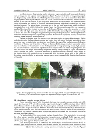
In addition to detecting the state of a drowsy face, determining the direction of the vehicle's
movement on the road and detecting obstacles also helps warn of unexpected incidents. Nugraha et al. [24]
used the you only look once network (YOLO) as the object detector and polynomial regression as the road
guidance. Kemsaram et al. [25] presented a neural network to detect lane markings, objects, using a
monocular. Another work presented a lane detection algorithm based on the combined CNN with the random
sample consensus (RANSAC) approach [26]. It can be seen that the works mentioned are partially or
incompletely resolved for drowsiness detection and driver warning systems.
In order to improve the accuracy and speed of facial information processing, as well as the detection
of objects on the road, this study introduces new approaches. Two cameras are used to directly observe the
driver's face and objects on the road, employing rapid image processing methods to recognize and assess the
driver's drowsy situation. This image processing method utilizes a novel approach to determine benchmark
points and characteristic white areas on the face and in the eyes. Additionally, lanes, obstacles, and traffic
signs are identified to assess the level of danger to vehicles and drivers. In the event of distraction, an on-
board warning system will trigger a signal to alert the driver. Simultaneously, the driver's information will be
transmitted to the monitoring system or the vehicle management department.
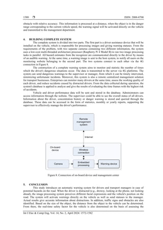
The article comprises three main parts. Section 2 introduces a method to identify distractions based
on benchmarks and white areas of the face. The image separation method, applying the fast image
recognition algorithm, is proposed in section 3. Section 4 provides a description of the complete monitoring
system, outlining the practical application of the results. Finally, Section 5 contains conclusions.
2. FACE IMAGE RECOGNITION ALGORITHM
The observations and studies clearly indicate that the most prominent signs of driver distraction are
the tilt of the head and eye gestures. In such cases, the eyes tend to remain closed for a longer duration than
during regular blinking, and the head is typically bent or slightly tilted for an extended period. The position
of the head may suggest that the driver is either distracted due to drowsiness or focused on objects not on the
road ahead. The algorithm for determining the head tilt and eye-closed state is illustrated in Figure 1. The
process involves analyzing the original camera image to ascertain the position of the driver's head.
Subsequently, the degree of head tilt and eye closure is transmitted to the evaluation and analysis block. In
situations of potential danger, both the on-board warning system and the remote management alert are
activated.
Figure 1. Distracted state identification process
2.1. Determine head tilt angle
To assess facial features, it is essential to determine the position of the head in the image. Digital
camera images undergo preprocessing steps, including conversion to grayscale and filtering image noise. The
resulting image is then input into the initial face recognition model. Face recognition can be achieved through
various methods, such as the AdaBoost classification algorithm using Haar-like features, which is available
in the OpenCV library. Additionally, methods like histogram of oriented gradients and linear support vector
machine, pre-trained for face detection, can be applied. Deep learning algorithms are also employed for
locating face coordinates in images.](https://image.slidesharecdn.com/v3531595ijecedby-240405053412-1dc95d88/85/Effective-driver-distraction-warning-system-incorporating-fast-image-recognition-methods-3-320.jpg)
![ ISSN: 2088-8708
Int J Elec & Comp Eng, Vol. 14, No. 2, April 2024: 1572-1582
1576
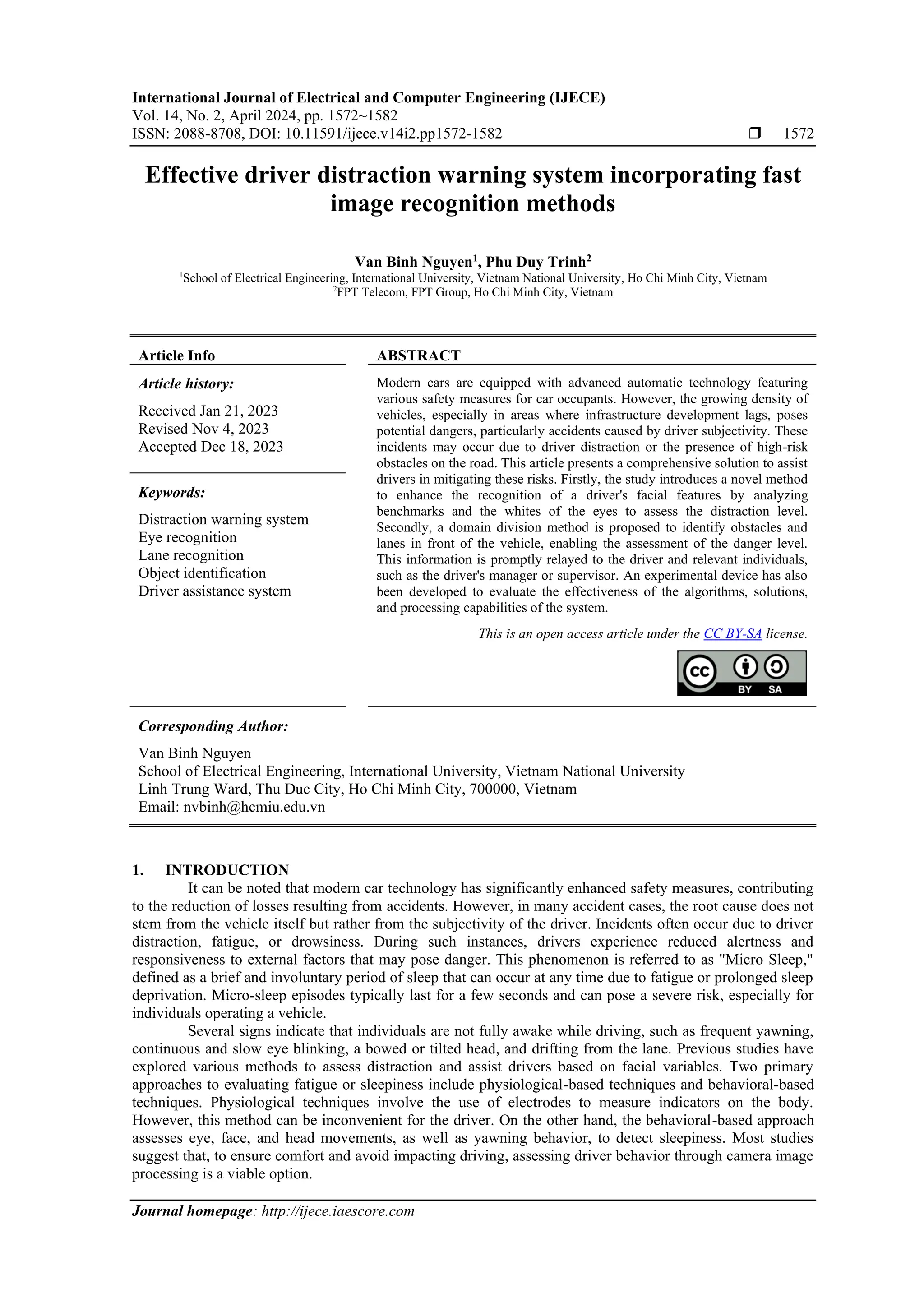
(a) (b)
(c) (d)
Figure 3. Results of identifying facial points with different tilt states of the head, including (a) normal head
state, (b) forward head tilt state, (c) slight head tilt to the left, and (d) strong head tilt to the left
2.2. Eye state recognition
In most cases, a medium-quality camera can be used to receive images of the eye for recognition
algorithms. In case of necessity, different types of cameras can be used to improve the results of eye status
assessment such as infrared cameras [17], or glasses with specialized cameras [21]. The work in this paper
implements an algorithm for analyzing eye states using a standard camera in normal lighting conditions.
Many methods have been presented to automatically detect blinks in a sequence of images in a
video. Nevertheless, a major drawback of previous approaches is their dependency on various factors when
setting up the recognition model. These approaches are influenced by factors such as camera angle, image
resolution, light source hitting the eye, or movements of the driver being detected. To address this problem,
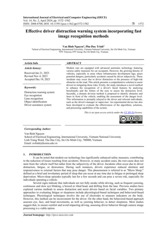
this study continues to use the points identified, as shown in Figure 2. From the position coordinates of the
recognized eye landmarks, determining the state of sleepiness is possible by relying on the longer duration of
the blinking state. Each person has a different blink pattern in terms of how fast they open and close their
eyes, how wide the eyes are when opened and closed, and the blink cycle or average time between blinks.
Normally, a blink lasts about 100 to 400 ms. In this study, blinks lasting more than 1,200 ms are considered
distracting.
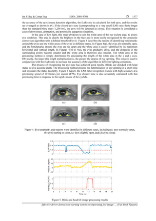
The proposed method in this study leverages the performance of the facial Landmark detector to
recognize the position of the eye and the contour of the eye on the image frame. It identifies the bright sclera
area of the eye, as the sclera region has the advantage of having the highest brightness on the face, making it
more easily detected, especially in low-light conditions. From landmark points, the algorithm calculates the
eye aspect ratio (EAR) to estimate the eye's open state. The EAR ratio based on eye height and width is
calculated using (2). The positions of the points to determine this ratio are shown in Figure 4. For different
eye states, the benchmark points will shift accordingly. The denominator part of the formula is multiplied by
the factor k. This is a factor that depends on eye shape. If the eye opening is small, the k-factor is usually set
to less than 1. This is to improve the sensitivity of the eye state assessment.
𝐸𝐴𝑅1 =
|𝑦4−𝑦3|+|𝑦6−𝑦5|
𝑘|𝑥2−𝑥1|
(2)
𝐸𝐴𝑅2 =
|𝑦10−𝑦9|+|𝑦12−𝑦11|
𝑘|𝑥8−𝑥7|
(3)
𝐸𝐴𝑅 =
𝐸𝐴𝑅1+𝐸𝐴𝑅2
2
(4)
With the calculation of the eye-opening characteristic by EAR, the calculated value is less affected
by the position and relative tilt of the head. Different individuals will have different EAR rates. To increase](https://image.slidesharecdn.com/v3531595ijecedby-240405053412-1dc95d88/85/Effective-driver-distraction-warning-system-incorporating-fast-image-recognition-methods-5-320.jpg)

![Int J Elec & Comp Eng ISSN: 2088-8708
Effective driver distraction warning system incorporating fast image … (Van Binh Nguyen)
1581
direction of the vehicle's movement. Research results show that the system adapts well in normal conditions
with medium light with fast response speed. In low-light conditions, the application of white area recognition
gives positive results, improving the system's reliability. The widespread application of this system greatly
reduces the risks from the driver's subjectivity, as well as from unusual factors on the road.
REFERENCES
[1] W.-B. Horng, C.-Y. Chen, Y. Chang, and C.-H. Fan, “Driver fatigue detection based on eye tracking and dynamic template
matching,” in IEEE International Conference on Networking, Sensing and Control, 2004, 2004, pp. 7–12, doi:
10.1109/ICNSC.2004.1297400.
[2] L. M. Bergasa, J. Nuevo, M. A. Sotelo, and M. Vazquez, “Real-time system for monitoring driver vigilance,” in IEEE Intelligent
Vehicles Symposium, 2004, pp. 78–83, doi: 10.1109/IVS.2004.1336359.
[3] A. Rahman, M. Sirshar, and A. Khan, “Real time drowsiness detection using eye blink monitoring,” in 2015 National Software
Engineering Conference (NSEC), Dec. 2015, pp. 1–7, doi: 10.1109/NSEC.2015.7396336.
[4] S. Vitabile, A. De Paola, and F. Sorbello, “A real-time non-intrusive FPGA-based drowsiness detection system,” Journal of
Ambient Intelligence and Humanized Computing, vol. 2, no. 4, pp. 251–262, Dec. 2011, doi: 10.1007/s12652-011-0049-z.
[5] M. J. Flores, J. M. Armingol, and A. de la Escalera, “Real-time warning system for driver drowsiness detection using visual
information,” Journal of Intelligent & Robotic Systems, vol. 59, no. 2, pp. 103–125, Aug. 2010, doi: 10.1007/s10846-009-9391-1.
[6] J. Xu, J. Min, and J. Hu, “Real‐time eye tracking for the assessment of driver fatigue,” Healthcare Technology Letters, vol. 5,
no. 2, pp. 54–58, Apr. 2018, doi: 10.1049/htl.2017.0020.
[7] M. W. Johns, A. Tucker, R. Chapman, K. Crowley, and N. Michael, “Monitoring eye and eyelid movements by infrared
reflectance oculography to measure drowsiness in drivers,” Somnologie - Schlafforschung und Schlafmedizin, vol. 11, no. 4,
pp. 234–242, Dec. 2007, doi: 10.1007/s11818-007-0311-y.
[8] L. Lin et al., “Driver fatigue detection based on eye state,” Technology and Health Care, vol. 23, no. s2, pp. S453–S463, Jun.
2015, doi: 10.3233/THC-150982.
[9] N. Kumar, N. C. Barwar, and N. Kuamr, “Analysis of real time driver fatigue detection based on eye and yawning,” International
Journal of Computer Science and Information Technologies, vol. 5, no. 6, pp. 7821–7826, 2014.
[10] I. Teyeb, O. Jemai, M. Zaied, and C. Ben Amar, “A novel approach for drowsy driver detection using head posture estimation and
eyes recognition system based on wavelet network,” in IISA 2014, The 5th International Conference on Information, Intelligence,
Systems and Applications, Jul. 2014, pp. 379–384, doi: 10.1109/IISA.2014.6878809.
[11] O. Khunpisuth, T. Chotchinasri, V. Koschakosai, and N. Hnoohom, “Driver drowsiness detection using eye-closeness detection,”
in 2016 12th International Conference on Signal-Image Technology & Internet-Based Systems (SITIS), 2016, pp. 661–668, doi:
10.1109/SITIS.2016.110.
[12] Q. Ji and X. Yang, “Real-time eye, gaze, and face pose tracking for monitoring driver vigilance,” Real-Time Imaging, vol. 8,
no. 5, pp. 357–377, Oct. 2002, doi: 10.1006/rtim.2002.0279.
[13] M. Saradadevi and P. Bajaj, “Driver fatigue detection using mouth and yawning analysis,” International journal of Computer
science and network security, vol. 8, no. 6, pp. 183–188, 2008.
[14] N. Alioua, A. Amine, and M. Rziza, “Driver’s fatigue detection based on yawning extraction,” International Journal of Vehicular
Technology, vol. 2014, pp. 1–7, Aug. 2014, doi: 10.1155/2014/678786.
[15] A. Tawari, S. Martin, and M. M. Trivedi, “Continuous head movement estimator for driver assistance: Issues, algorithms, and on-
road evaluations,” IEEE Transactions on Intelligent Transportation Systems, vol. 15, no. 2, pp. 818–830, Apr. 2014, doi:
10.1109/TITS.2014.2300870.
[16] T. Liu, “Driver’s face detection using space-time restrained Adaboost method,” KSII Transactions on Internet and Information
Systems, 2012, doi: 10.3837/tiis.2012.09.021.
[17] G. Salzillo, C. Natale, G. B. Fioccola, and E. Landolfi, “Evaluation of driver drowsiness based on real-time face analysis,” in
2020 IEEE International Conference on Systems, Man, and Cybernetics (SMC), Oct. 2020, pp. 328–335, doi:
10.1109/SMC42975.2020.9283133.
[18] B. Akrout and W. Mahdi, “A novel approach for driver fatigue detection based on visual characteristics analysis,” Journal of
Ambient Intelligence and Humanized Computing, vol. 14, no. 1, pp. 527–552, Jan. 2023, doi: 10.1007/s12652-021-03311-9.
[19] M. A. Assari and M. Rahmati, “Driver drowsiness detection using face expression recognition,” in 2011 IEEE International
Conference on Signal and Image Processing Applications (ICSIPA), Nov. 2011, pp. 337–341, doi:
10.1109/ICSIPA.2011.6144162.
[20] R. Ahmad and J. N. Borole, “Drowsy driver identification using eye blink detection,” IJISET-International Journal of Computer
Science and Information Technologies, vol. 6, no. 1, pp. 270–274, 2015.
[21] T. Li and X. Zhou, “Battery-free eye tracker on glasses,” in Proceedings of the 24th Annual International Conference on Mobile
Computing and Networking, Oct. 2018, pp. 67–82, doi: 10.1145/3241539.3241578.
[22] B. P. Doppala, B. Vamsi, D. Bhattacharyya, and J. N. Rao, “A machine intelligence model to detect drowsiness for preventing
road accidents,” in 2022 International Conference on Applied Artificial Intelligence and Computing (ICAAIC), May 2022,
pp. 406–411, doi: 10.1109/ICAAIC53929.2022.9793256.
[23] A. V. Sant, A. S. Naik, A. Sarkar, and V. Dixit, “Driver drowsiness detection and alert system: a solution for ride-hailing and
logistics companies,” in 2021 IEEE Pune Section International Conference (PuneCon), Dec. 2021, pp. 1–5, doi:
10.1109/PuneCon52575.2021.9686546.
[24] B. T. Nugraha, S.-F. Su, and Fahmizal, “Towards self-driving car using convolutional neural network and road lane detector,” in
2017 2nd International Conference on Automation, Cognitive Science, Optics, Micro Electro--Mechanical System, and
Information Technology (ICACOMIT), Oct. 2017, pp. 65–69, doi: 10.1109/ICACOMIT.2017.8253388.
[25] N. Kemsaram, A. Das, and G. Dubbelman, “An integrated framework for autonomous driving: object detection, lane detection,
and free space detection,” in 2019 Third World Conference on Smart Trends in Systems Security and Sustainablity (WorldS4), Jul.
2019, pp. 260–265, doi: 10.1109/WorldS4.2019.8904020.
[26] J. Kim and M. Lee, “Robust lane detection based on convolutional neural network and random sample consensus,” in Neural
Information Processing: 21st International Conference, ICONIP 2014, Kuching, Malaysia, November 3-6, 2014. Proceedings,
Part I 21, 2014, pp. 454–461.](https://image.slidesharecdn.com/v3531595ijecedby-240405053412-1dc95d88/85/Effective-driver-distraction-warning-system-incorporating-fast-image-recognition-methods-10-320.jpg)