1. Install the motherboard into the computer case and secure it using screws.
2. Install the processor and cooling fan onto the CPU socket.
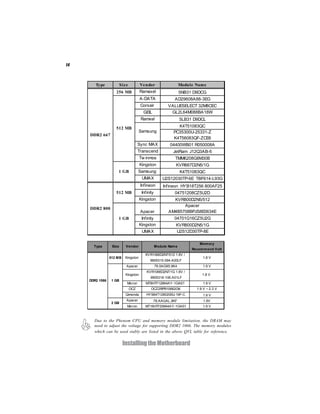
3. Install memory modules into the DIMM slots.
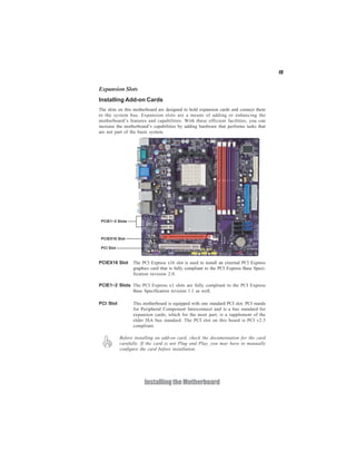
4. Install expansion cards such as graphics cards into the PCI and PCIe slots.
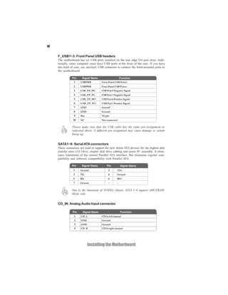
5. Connect power cables, front panel connectors, and drives to the motherboard.
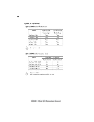
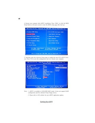
6. Configure BIOS settings before installing the operating system.


![28
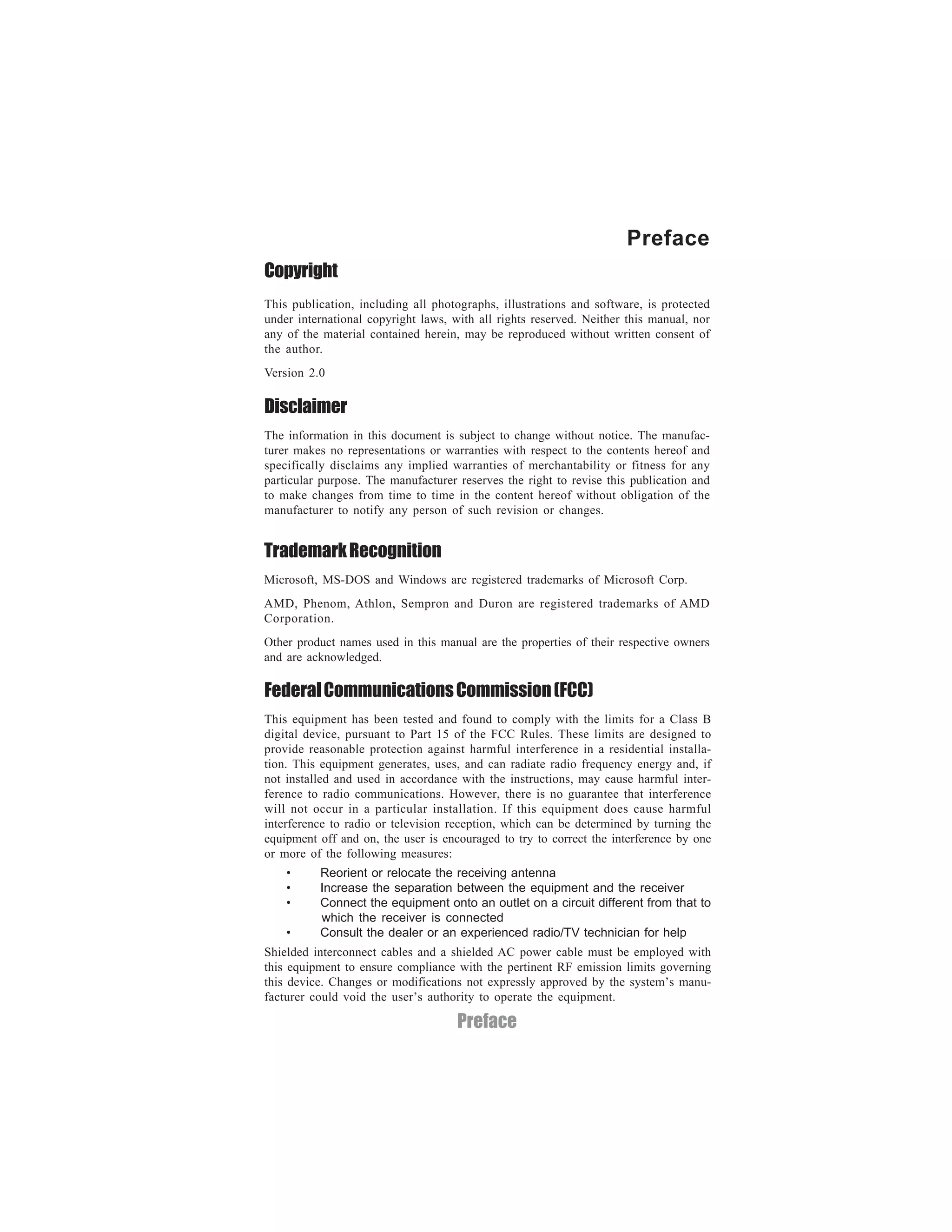
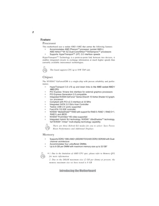
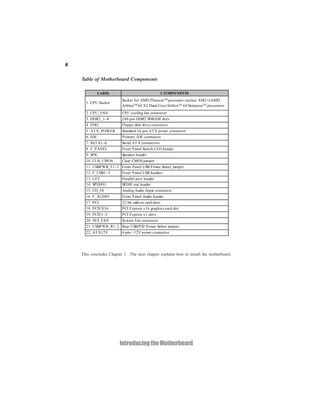
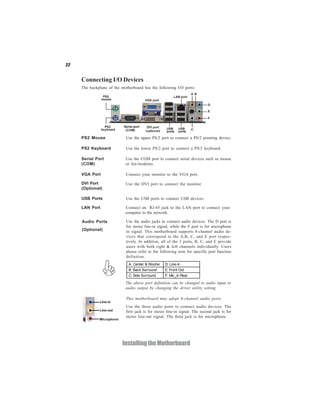
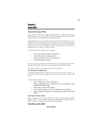
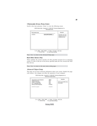
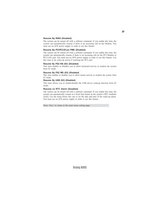
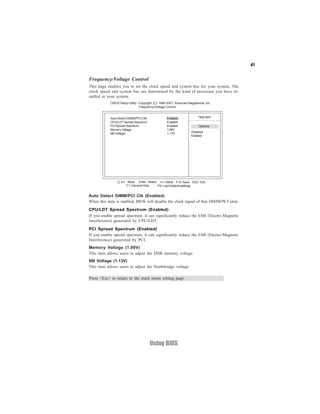
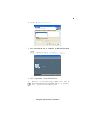
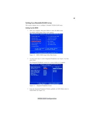
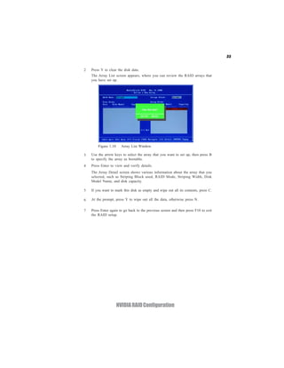
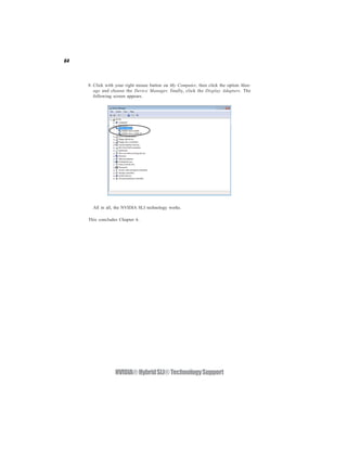
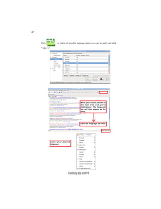
Press the delete key to access the BIOS Setup Utility.
CMOS Setup Utility -- Copyright (C) 1985-2007, American Megatrends, Inc.
Standard CMOS Setup Frequency/Voltage Control
Advanced Setup Load Default Settings
Advanced Chipset Setup Supervisor Password
Integrated Peripherals User Password
Power Management Setup Save & Exit Setup
PCI/PnP Setup Exit Without Saving
PC Health Status
< > : Move Enter : Select +/-/: Value F10: Save ESC: Exit
F1:General Help F9: Load Default settings
v02.61 (C)Copyright 1985-2007, American Mega trends, Inc.
Resetting the Default CMOS Values
When powering on for the first time, the POST screen may show a “CMOS
Settings Wrong” message. This standard message will appear following a clear
CMOS data at factory by the manufacturer. You simply need to Load Default
Settings to reset the default CMOS values.
Note: Changes to system hardware such as different CPU, memories, etc. may also
trigger this message.
CMOS Setup Utility -- Copyright (C) 1985-2007, American Megatrends, Inc.
Standard CMOS Setup Frequenvy/Voltage Control
Advanced Setup Load Default Settings
Advanced Chipset Setup Supervisor Password
Integrated Peripherals User Password
Power Management Setup Load Default Settings? Setup
Save & Exit
PCI/PnP Setup Exit Without Saving
PC Health Status [Ok] [Cancel]
: Move Enter : Select +/-/: Value F10: Save ESC: Exit
F1:General Help F9: Load Default Settings
v02.61 (C)Copyright 1985-2007, American Mega trends, Inc.
Using BIOS](https://image.slidesharecdn.com/ecsgf8200sm-m3manuala-100427155225-phpapp02/85/Ecs-gf8200-sm-m3-manuala-32-320.jpg)
![30
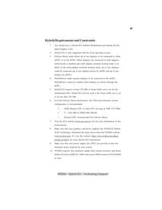
For the purpose of better product maintenance, the manufacture reserves
the right to change the BIOS items presented in this manual. The BIOS
setup screens shown in this chapter are for reference only and may differ
from the actual BIOS. Please visit the manufacture’s website for updated
manual.
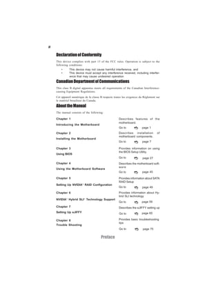
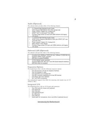
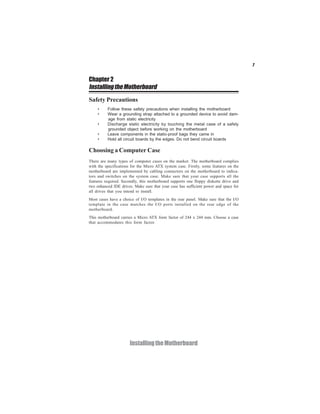
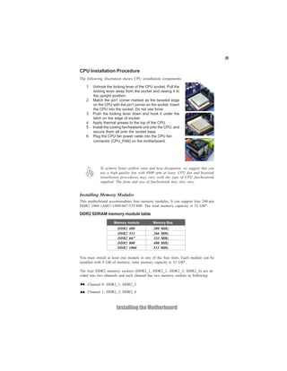
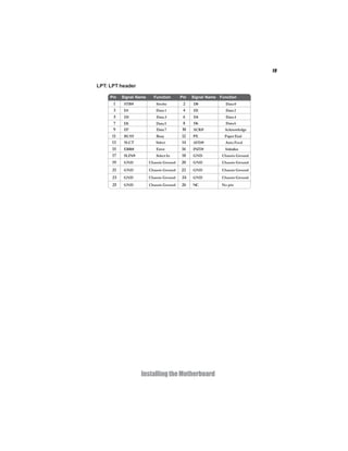
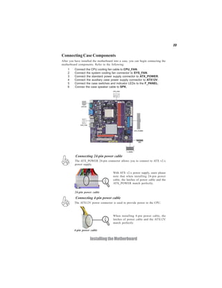
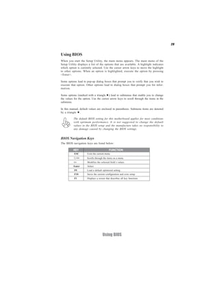
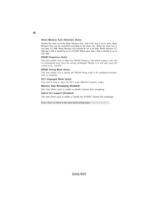
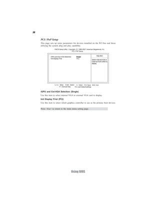
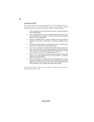
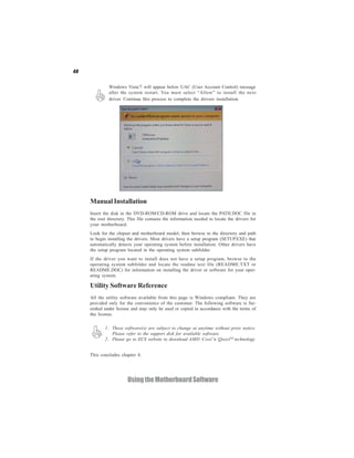
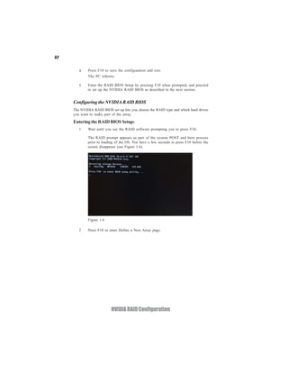
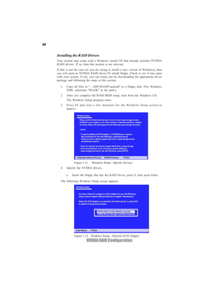
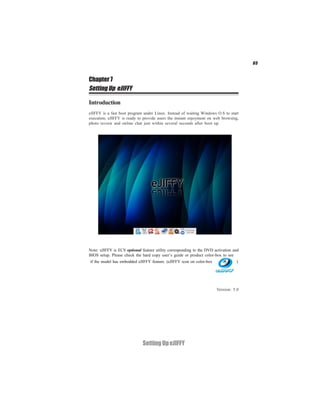
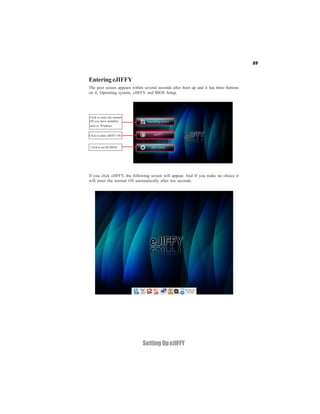
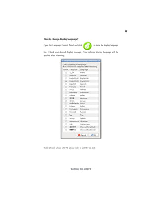
Standard CMOS Setup
This option displays basic information about your system.
CMOS Setup Utility -- Copyright (C) 1985-2007, American Megatrends, Inc.
Standard CMOS Setup
Date Tue 03/10/2008 Help Item
Time 00:06:58
User [Enter], [TAB]
SATA 1 Not Detected
or [SHIFT-TAB] to
SATA 2 Not Detected
select a field.
SATA 3 Not Detected
SATA 4 Not Detected
Use [+] or [-] to
Primary IDE Master Not Detected
configure system Date.
Primary IDE Slave Not Detected
IDE BusMaster Enabled
Drive A: 1.44 MB 31/2”
< > : Move Enter : Select +/-/: Value F10: Save ESC: Exit
F1: General Help F9: Load Default settings
Date & Time
The Date and Time items show the current date and time on the computer. If you are
running a Windows OS, these items are automatically updated whenever you make
changes to the Windows Date and Time Properties utility.
SATA 1~4/Primary IDE Master/Slave
Your computer has one IDE channel which can be installed with one or two devices
(Master and Slave). In addition, this motherboard supports six SATA channels and
each channel allows one SATA device to be installed. Use these items to configure
each device on the IDE channel.
CMOS SETUP UTILITY - Copyright (C) 1985-2007, American Megatrends, Inc.
SATA 1
SATA 1
Help Item
Device : Not Detected
Select the type
Type Auto of device connected
LBA/Large Mode Auto to the system.
Block Mode Auto
PIO Mode Auto
DMA Mode Auto
S.M.A.R.T Auto
32Bit Data Transfer Enabled
< > : Move Enter : Select +/-/: Value F10: Save ESC: Exit
F1: General Help F9: Load Default settings
Using BIOS](https://image.slidesharecdn.com/ecsgf8200sm-m3manuala-100427155225-phpapp02/85/Ecs-gf8200-sm-m3-manuala-34-320.jpg)
![42
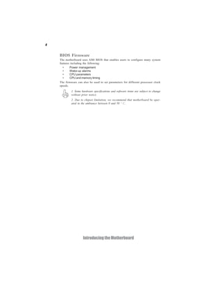
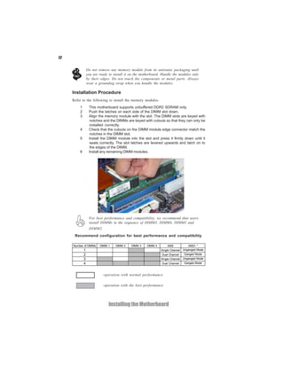
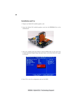
Load Default Settings
This option opens a dialog box to ask if you are sure to install optimized defaults or
not. You select [OK], and then <Enter>, the Setup Utility loads all default values; or
select [Cancel], and then <Enter>, the Setup Utility does not load default values.
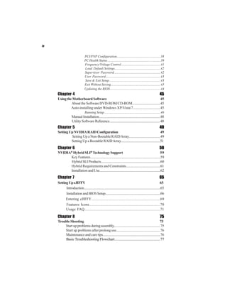
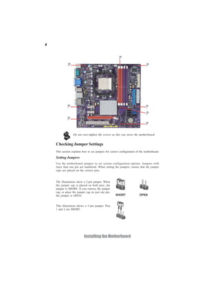
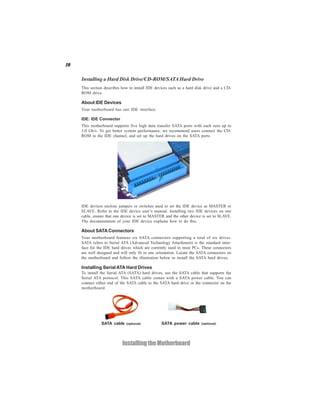
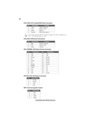
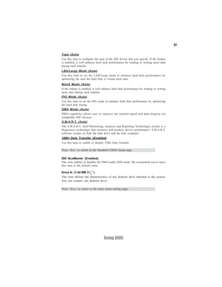
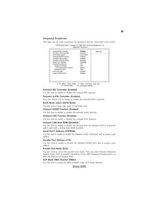
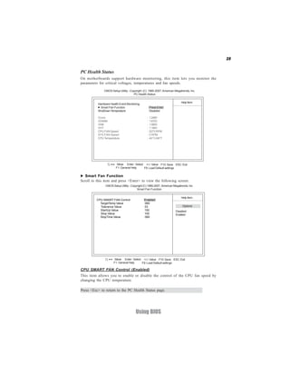
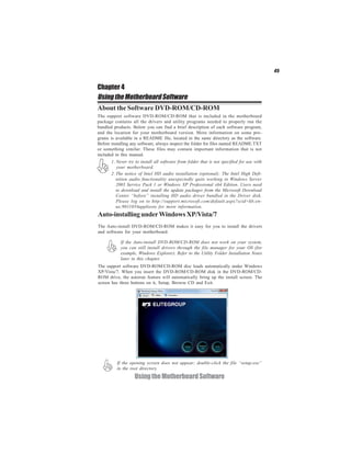
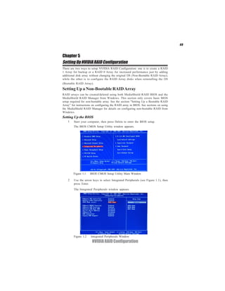
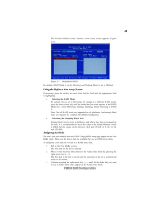
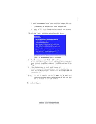
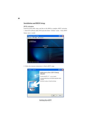
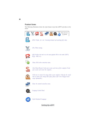
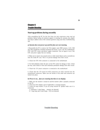
Supervisor Password
This page helps you install or change a password.
CMOS Setup Utility - Copyright (C) 1985-2007, American Megatrends, Inc.
Supervisor Password
Help item
Supervisor Password :Not Installed
Change Supervisor Password Press Enter Install or Change the
password.
< > : Move Enter : Select +/-/: Value F10: Save ESC: Exit
F1: General Help F9: Load Default settings
Supervisor Password (Not Installed)
This item indicates whether a supervisor password has been set. If the password has
been installed, Installed displays. If not, Not Installed displays.
Change Supervisor Password (Press Enter)
You can select this option and press <Enter> to access the sub menu. You can use the
sub menu to change the supervisor password.
Press <Esc> to return to the main menu setting page.
Using BIOS](https://image.slidesharecdn.com/ecsgf8200sm-m3manuala-100427155225-phpapp02/85/Ecs-gf8200-sm-m3-manuala-46-320.jpg)
![43
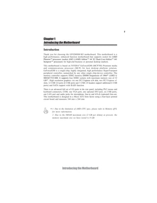
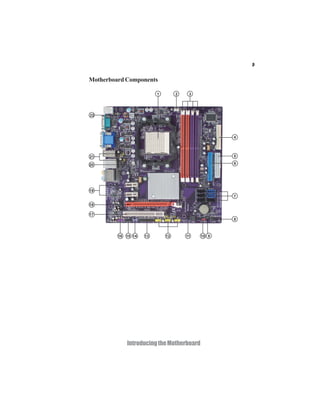
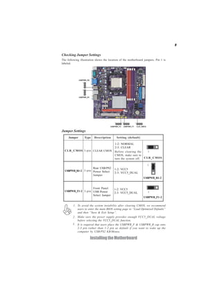
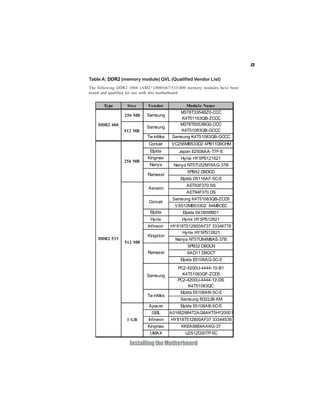
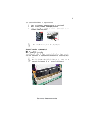
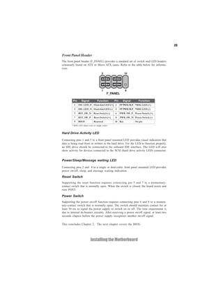
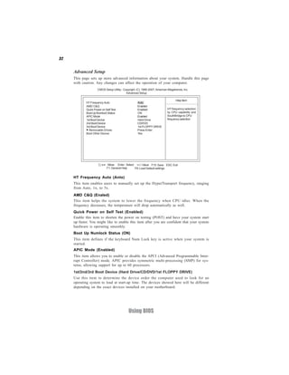
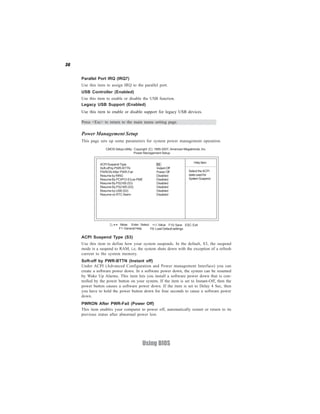
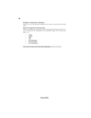
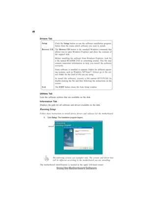
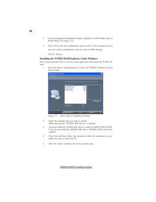
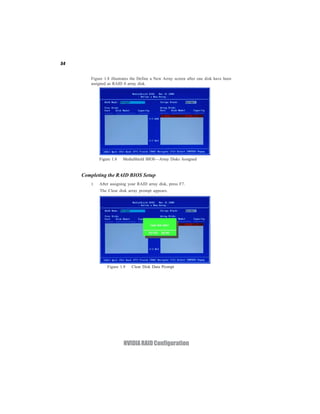
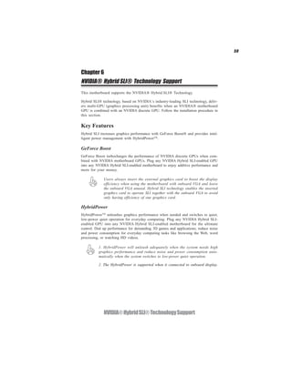
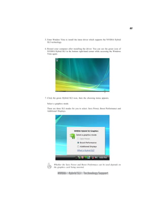
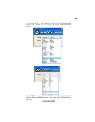
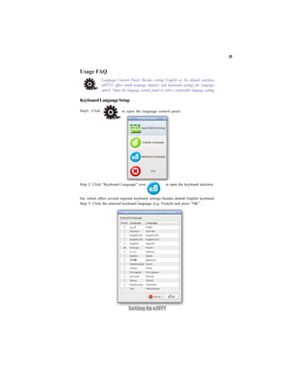
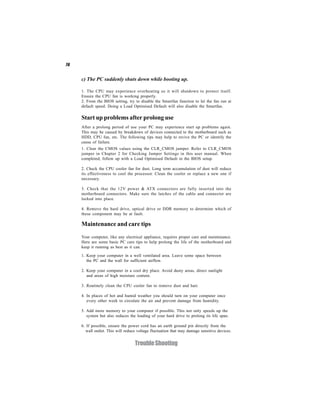
User Password
This page helps you install or change a password.
CMOS Setup Utility - Copyright (C) 1985-2007, American Megatrends, Inc.
User Password
User Password : Not Installed Help item
Change User Password Press Enter Install or Change the
password.
< > : Move Enter : Select +/-/: Value F10: Save ESC: Exit
F1: General Help F9: Load Default settings
User Password (Not Installed)
This item indicates whether a user password has been set. If the password has been
installed, Installed displays. If not, Not Installed displays.
Change User Password (Press Enter)
You can select this option and press <Enter> to access the sub menu. You can use the
sub menu to change the user password. This item will show if the supervisor password
is set.
Press <Esc> to return to the main menu setting page.
Save & Exit Setup
Highlight this item and press <Enter> to save the changes that you have made in the
Setup Utility and exit the Setup Utility. When the Save and Exit dialog box appears,
select [OK] to save and exit, or select [Cancel] to return to the main menu.
Exit Without Saving
Highlight this item and press <Enter> to discard any changes that you have made in
the Setup Utility and exit the Setup Utility. When the Exit Without Saving dialog
box appears, select [OK] to discard changes and exit, or select [Cancel] to return to
the main menu.
If you have made settings that you do not want to save, use the “Exit Without
Saving” item and select [OK] to discard any changes you have made.
Using BIOS](https://image.slidesharecdn.com/ecsgf8200sm-m3manuala-100427155225-phpapp02/85/Ecs-gf8200-sm-m3-manuala-47-320.jpg)


![Subrogation othman bin hashim v kkw auto centre [2012] hc](https://cdn.slidesharecdn.com/ss_thumbnails/subrogationothmanbinhashimvkkwautocentre2012hc-140312201244-phpapp01-thumbnail.jpg?width=640&height=640&fit=bounds)


