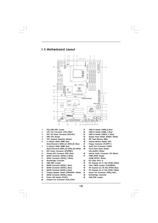
This document is the user manual for the ASRock 770 Extreme3 motherboard. It includes specifications for the motherboard such as the CPU, chipset, memory, expansion slots, audio, LAN, rear I/O, connectors, BIOS features, and support software. The manual provides instructions on installing the motherboard components like the CPU, memory, and expansion cards. It also covers BIOS setup and configuring settings like the overclocking features and fan controls.
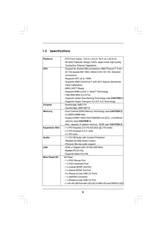
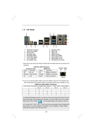
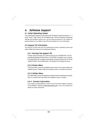
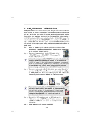
![1. High Definition Audio supports Jack Sensing, but the panel wire on
the chassis must support HDA to function correctly. Please follow the
instruction in our manual and chassis manual to install your system.
2. If you use AC’97 audio panel, please install it to the front panel audio
header as below:
A. Connect Mic_IN (MIC) to MIC2_L.
B. Connect Audio_R (RIN) to OUT2_R and Audio_L (LIN) to OUT2_L.
C. Connect Ground (GND) to Ground (GND).
D. MIC_RET and OUT_RET are for HD audio panel only. You don’t
need to connect them for AC’97 audio panel.
E. Enter BIOS Setup Utility. Enter Advanced Settings, and then select
Chipset Configuration. Set the Front Panel Control option from
[Auto] to [Enabled].
F. Enter Windows system. Click the icon on the lower right hand
taskbar to enter Realtek HD Audio Manager.
For Windows® XP / XP 64-bit OS:
Click “Audio I/O”, select “Connector Settings” , choose
“Disable front panel jack detection”, and save the change by
clicking “OK”.
For Windows® 7 / 7 64-bit / VistaTM / VistaTM 64-bit OS:
Click the right-top “Folder” icon , choose “Disable front
panel jack detection”, and save the change by clicking “OK”.
G. To activate the front mic.
For Windows® XP / XP 64-bit OS:
Please select “Front Mic” as default record device.
If you want to hear your voice through front mic, please deselect "Mute"
icon in “Front Mic” of “Playback” portion.
For Windows® 7 / 7 64-bit / VistaTM / VistaTM 64-bit OS:
Go to the "Front Mic" Tab in the Realtek Control panel.
Click "Set Default Device" to make the Front Mic as the default record
device.
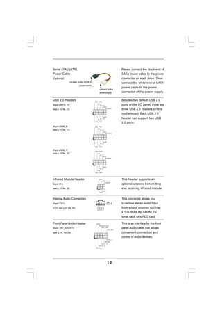
System Panel Header PLED+ This header accommodates
PLED-
(9-pin PANEL1) PWRBTN#
GND
several system front panel
(see p.10 No. 24) functions.
1
DUMMY
RESET#
GND
HDLED-
HDLED+
20](https://image.slidesharecdn.com/manual770extreme3-110621134401-phpapp01/85/Manual-770-extreme3-20-320.jpg)
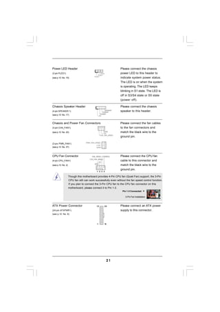
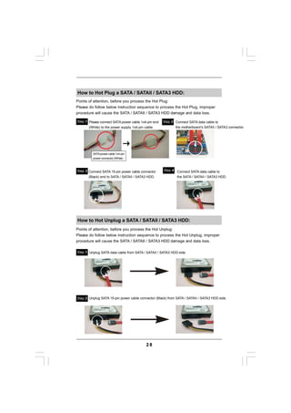
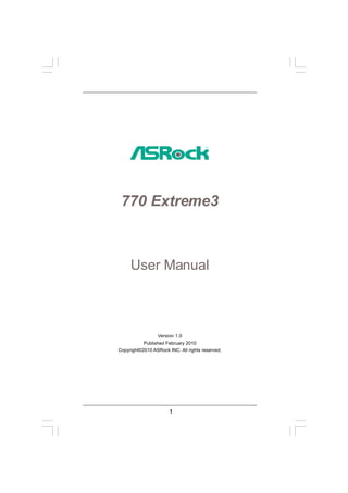
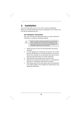
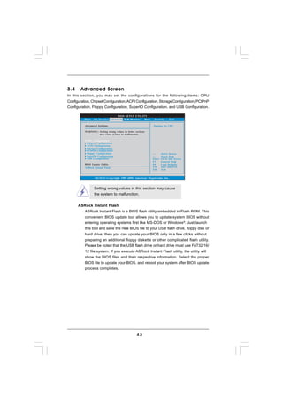
![2.13 Driver Installation Guide
To install the drivers to your system, please insert the support CD to your optical
drive first. Then, the drivers compatible to your system can be auto-detected and
listed on the support CD driver page. Please follow the order from up to bottom
side to install those required drivers. Therefore, the drivers you install can work
properly.
2.14 Installing Windows ® 7 / 7 64-bit / Vista TM /
Vista TM 64-bit / XP / XP 64-bit With RAID Functions
If you want to install Windows® 7 / 7 64-bit / VistaTM / VistaTM 64-bit / XP / XP 64-bit on
a RAID disk composed of 2 or more SATA / SATAII HDDs with RAID functions, please
follow below procedures according to the OS you install.
2.14.1 Installing Windows ® XP / XP 64-bit With RAID
Functions
Functions
If you want to install Windows® XP / XP 64-bit on a RAID disk composed of 2 or more
SATA / SATAII HDDs with RAID functions, please follow below steps.
STEP 1: Set up BIOS.
A. Enter BIOS SETUP UTILITY Advanced screen Storage
Configuration.
B. Set the “SATA Operation Mode” option to [RAID].
STEP 2: Make a SATA / SATAII Driver Diskette.
A. Insert the ASRock Support CD into your optical drive to boot your system.
B. During POST at the beginning of system boot-up, press <F11> key, and
then a window for boot devices selection appears. Please select CD-ROM
as the boot device.
C. When you see the message on the screen, “Generate Serial ATA driver
diskette [YN]?”, press <Y>.
D. Then you will see these messages,
Please insert a blank
formatted diskette into floppy
drive A:
press any key to start
Please insert a floppy diskette into the floppy drive, and press any key.
E. The system will start to format the floppy diskette and copy SATA / SATAII
drivers into the floppy diskette.
29](https://image.slidesharecdn.com/manual770extreme3-110621134401-phpapp01/85/Manual-770-extreme3-29-320.jpg)
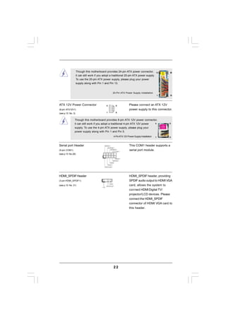
![STEP 3: Use “RAID Installation Guide” to set RAID configuration.
Before you start to configure RAID function, you need to check the RAID installation
guide in the Support CD for proper configuration. Please refer to the BIOS RAID installation
guide part of the document in the following path in the Support CD:
.. RAID Installation Guide
STEP 4: Install Windows® XP / XP 64-bit OS on your system.
After step 1, 2, 3, you can start to install Windows® XP / XP 64-bit OS on your system.
At the beginning of Windows ® setup, press F6 to install a third-party RAID driver.
When prompted, insert the SATA / SATAII driver diskette containing the AMD RAID
driver. After reading the floppy disk, the driver will be presented. Select the driver to
install according to the OS you install. (Select “AMD AHCI Compatible RAID Controller-
x86 platform” for Windows® XP, or “AMD AHCI Compatible RAID Controller-x64 platform”
for Windows® XP 64-bit.)
NOTE. If you install Windows® XP / XP 64-bit on IDE HDDs and want to manage
(create, convert, delete, or rebuild) RAID functions on SATA / SATAII HDDs, you still
need to set up “SATA Operation Mode” to [RAID] first. Then, please set the RAID
configuration by using the Windows RAID installation guide in the following path in
the Support CD:
.. RAID Installation Guide
2.14.2 Installing Windows ® 7 / 7 64-bit / Vista TM /
Vista TM 64-bit With RAID Functions
If you want to install Windows® 7 / 7 64-bit / VistaTM / VistaTM 64-bit on a RAID disk
composed of 2 or more SATA / SATAII HDDs with RAID functions, please follow
below steps.
STEP 1: Set up BIOS.
A. Enter BIOS SETUP UTILITY Advanced screen Storage
Configuration.
B. Set the “SATA Operation Mode” option to [RAID].
STEP 2: Use “RAID Installation Guide” to set RAID configuration.
Before you start to configure RAID function, you need to check the RAID installation
guide in the Support CD for proper configuration. Please refer to the BIOS RAID installation
guide part of the document in the following path in the Support CD:
.. RAID Installation Guide
STEP 3: Install Windows® 7 / 7 64-bit / VistaTM / VistaTM 64-bit OS on your
system.
Insert the Windows® 7 / 7 64-bit / VistaTM / VistaTM 64-bit optical disk into the optical
drive to boot your system, and follow the instruction to install Windows® 7 / 7 64-bit
/ VistaTM / VistaTM 64-bit OS on your system. When you see “Where do you want to
install Windows?” page, please insert the ASRock Support CD into your optical drive,
and click the “Load Driver” button on the left on the bottom to load the AMD RAID
30](https://image.slidesharecdn.com/manual770extreme3-110621134401-phpapp01/85/Manual-770-extreme3-30-320.jpg)
![drivers. AMD RAID drivers are in the following path in our Support CD:
.. I386 (For Windows® VistaTM OS)
.. AMD64 (For Windows® VistaTM 64-bit OS)
After that, please insert Windows® VistaTM / Windows® VistaTM 64-bit optical disk into
the optical drive again to continue the installation.
NOTE1. If you install Windows® 7 / 7 64-bit / VistaTM / VistaTM 64-bit on IDE HDDs and want
to manage (create, convert, delete, or rebuild) RAID functions on SATA / SATAII
HDDs, you still need to set up “SATA Operation Mode” to [RAID] in BIOS first. Then,
please set the RAID configuration by using the Windows RAID installation guide in
the following path in the Support CD:
.. RAID Installation Guide
NOTE2. Currently, if you install Windows® 7 / 7 64-bit / VistaTM / VistaTM 64-bit on IDE HDDs
and there are no SATA / SATAII device used, please set up “SATA Operation Mode”
to [IDE] in BIOS.
2.15 Installing Windows ® 7 / 7 64-bit / Vista TM /
Vista TM 64-bit / XP / XP 64-bit Without RAID Functions
If you want to install Windows® 7 / 7 64-bit / VistaTM / VistaTM 64-bit / XP / XP 64-bit OS
on your SATA / SATAII HDDs without RAID functions, please follow below procedures
according to the OS you install.
2.15.1 Installing Windows ® XP / XP 64-bit Without RAID
Functions
Functions
If you want to install Windows® XP / XP 64-bit on your SATA / SATAII HDDs without
RAID functions, please follow below steps.
Using SATA / SATAII HDDs with NCQ and Hot Plug functions
STEP 1: Set Up BIOS.
A. Enter BIOS SETUP UTILITY Advanced screen Storage
Configuration.
B. Set the “SATA Operation Mode” option to [IDE].
STEP 2: Make a SATA / SATAII driver diskette.
Make a SATA / SATAII driver diskette by following section 2.14.1 step 2 on page
29.
STEP 3: Set Up BIOS.
A. Enter BIOS SETUP UTILITY Advanced screen Storage
Configuration.
B. Set the “SATA Operation Mode” option to [AHCI].
31](https://image.slidesharecdn.com/manual770extreme3-110621134401-phpapp01/85/Manual-770-extreme3-31-320.jpg)
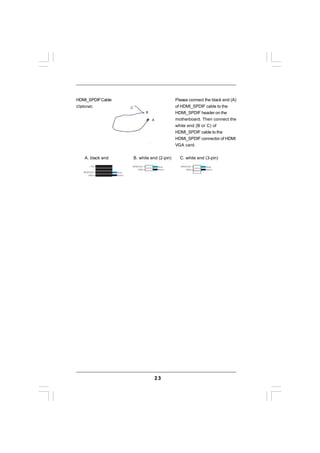
![STEP 4: Install Windows® XP / XP 64-bit OS on your system.
You can start to install Windows® XP / XP 64-bit OS on your system. At the beginning
of Windows® setup, press F6 to install a third-party AHCI driver. When prompted,
insert the SATA / SATAII driver diskette containing the AMD AHCI driver. After reading
the floppy disk, the driver will be presented. Select the driver to install according to
the OS you install. (Select “AMD AHCI Compatible RAID Controller-x86 platform” for
Windows® XP, or “AMD AHCI Compatible RAID Controller-x64 platform” for Windows®
XP 64-bit.)
Using SATA / SATAII HDDs without NCQ and Hot Plug functions
STEP 1: Set up BIOS.
A. Enter BIOS SETUP UTILITY Advanced screen Storage
Configuration.
B. Set the “SATA Operation Mode” option to [IDE].
STEP 2: Install Windows® XP / XP 64-bit OS on your system.
2.15.2 Installing Windows ® 7 / 7 64-bit / Vista TM /
Vista TM 64-bit Without RAID Functions
If you want to install Windows® 7 / 7 64-bit / VistaTM / VistaTM 64-bit on your SATA /
SATAII HDDs without RAID functions, please follow below steps.
Using SATA / SATAII HDDs with NCQ and Hot Plug functions
STEP 1: Set Up BIOS.
A. Enter BIOS SETUP UTILITY Advanced screen Storage
Configuration.
B. Set the “SATA Operation Mode” option to [AHCI].
STEP 2: Install Windows® 7 / 7 64-bit / VistaTM / VistaTM 64-bit OS on your
system.
Using SATA / SATAII HDDs without NCQ and Hot Plug functions
STEP 1: Set up BIOS.
A. Enter BIOS SETUP UTILITY Advanced screen Storage
Configuration.
B. Set the “SATA Operation Mode” option to [IDE].
STEP 2: Install Windows® 7 / 7 64-bit / VistaTM / VistaTM 64-bit OS on your
system.
32](https://image.slidesharecdn.com/manual770extreme3-110621134401-phpapp01/85/Manual-770-extreme3-32-320.jpg)
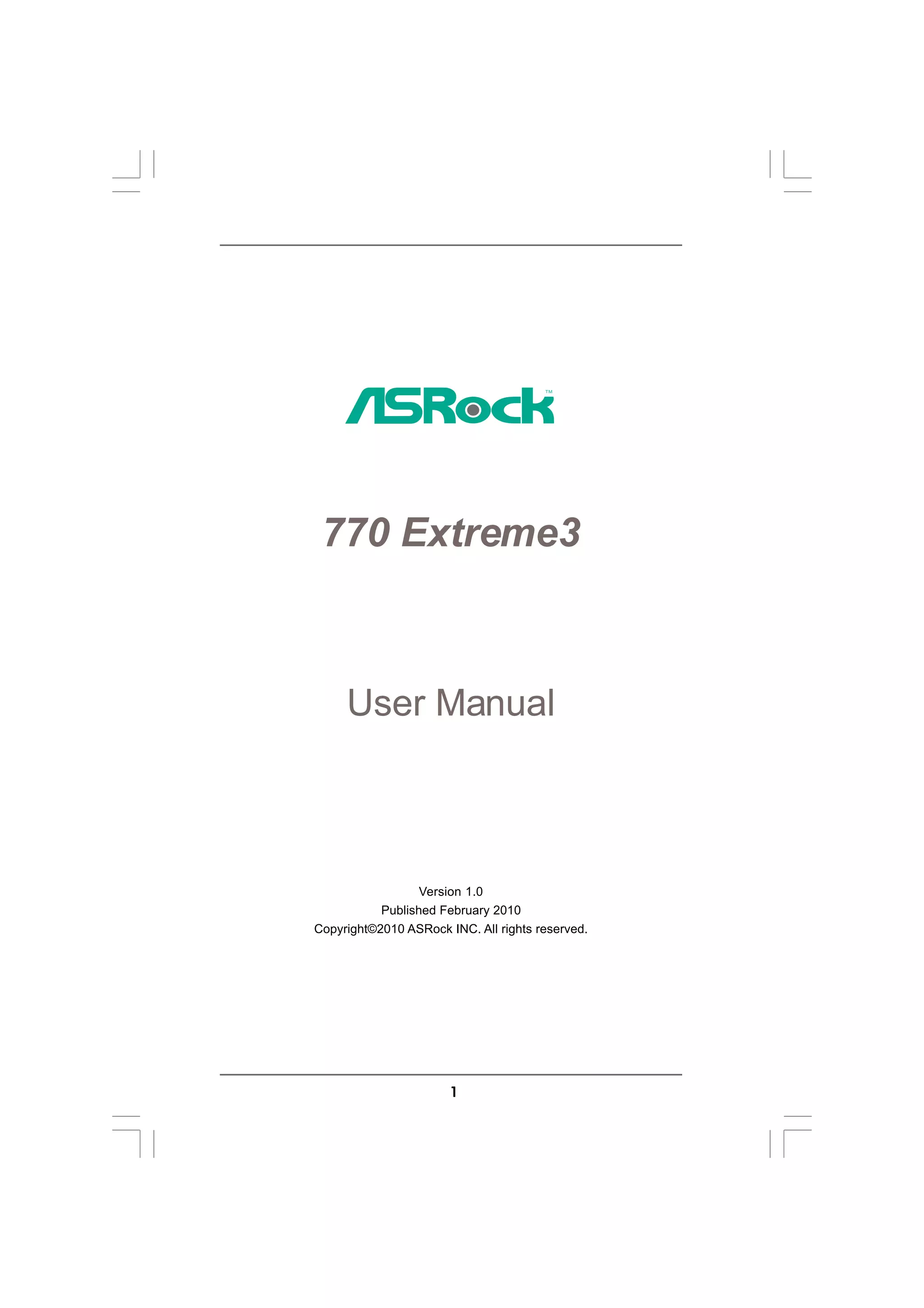
![Technology
2.16 Untied Overclocking Technology
This motherboard supports Untied Overclocking Technology, which means during
overclocking, FSB enjoys better margin due to fixed PCI / PCIE buses. Before you
enable Untied Overclocking function, please enter “Overclock Mode” option of BIOS
setup to set the selection from [Auto] to [CPU, PCIE, Async.]. Therefore, CPU FSB is
untied during overclocking, but PCI / PCIE buses are in the fixed mode so that FSB can
operate under a more stable overclocking environment.
Please refer to the warning on page 8 for the possible overclocking risk
before you apply Untied Overclocking Technology.
33](https://image.slidesharecdn.com/manual770extreme3-110621134401-phpapp01/85/Manual-770-extreme3-33-320.jpg)
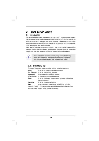
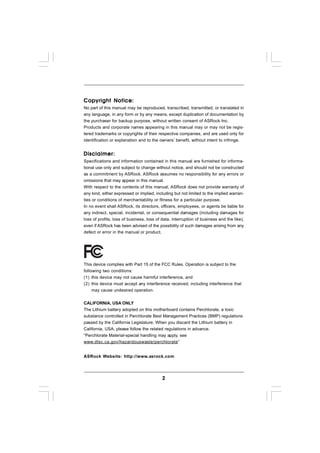
![3.1.2 Navigation Keys
Please check the following table for the function description of each navigation
key.
Navigation Key(s) Function Description
/ Moves cursor left or right to select Screens
/ Moves cursor up or down to select items
+ / - To change option for the selected items
<Enter> To bring up the selected screen
<F1> To display the General Help Screen
<F9> To load optimal default values for all the settings
<F10> To save changes and exit the BIOS SETUP UTILITY
<ESC> To jump to the Exit Screen or exit the current screen
3.2 Main Screen
When you enter the BIOS SETUP UTILITY, the Main screen will appear and display
the system overview.
BIOS SETUP UTILITY
Main OC Tweaker Advanced H/W Monitor Boot Security Exit
System Overview
Use [Enter], [TAB]
System Time [17:00:09] or [SHIFT-TAB] to
System Date [Tue 02/09/2010] select a field.
BIOS Version : A770 Extreme3 P1.00
Processor Type : AMD Phenom(tm) II X4 600e Use [+] or [-] to
Processor (64bit) configure system Time.
Processor Speed : 2200MHz
Microcode Update : 100F52/1000086
L1 Cache Size : 512KB
L2 Cache Size : 2048KB Select Screen
Select Item
Total Memory : 1024MB +- Change Field
Single-Channel Memory Mode Tab Select Field
DDR3_A1 : 1024MB/667MHz DDR3_1333 F1 General Help
DDR3_B1 : None F9 Load Defaults
DDR3_A2 : None F10 Save and Exit
DDR3_B2 : None ESC Exit
v02.54 (C) Copyright 1985-2005, American Megatrends, Inc.
System Time [Hour:Minute:Second]
Use this item to specify the system time.
System Date [Day Month/Date/Year]
Use this item to specify the system date.
35](https://image.slidesharecdn.com/manual770extreme3-110621134401-phpapp01/85/Manual-770-extreme3-35-320.jpg)
![Tweak
weaker
3.3 OC Tweaker Screen
In the OC Tweaker screen, you can set up overclocking features.
BIOS SETUP UTILITY
Main OC Tweaker Advanced H/W Monitor Boot Security Exit
EZ Overclocking
Overclocking may cause
Load Optimized CPU OC Setting [Press Enter] damage to your CPU and
motherboard.
CPU Configuration It should be done at
your own risk and
Overclock Mode [Auto]
expense.
CPU Frequency (MHZ) [200]
CPU DOC Frequency (MHZ) [Auto]
PCIE Frequency (MHz) [100]
Spread Spectrum [Auto]
Boot Failure Guard [Enabled]
Boot Failure Guard Count [3] Select Screen
Advanced Clock Calibration [Disabled] Select Item
CPU Active Core Control [All Cores] Enter Go to Sub Screen
F1 General Help
Processor Maximum Frequency x10.5 2100 MHZ F9 Load Defaults
North Bridge Maximum Frequency x9.0 18 00 MHz
Processor Maximum Voltage 1.2500 V F10 Save and Exit
Multiplier/Voltage Change [Auto] ESC Exit
v02.54 (C) Copyright 1985-2005, American Megatrends, Inc.
EZ Overclocking
Load Optimized CPU OC Setting
You can use this option to load the optiomized CPU overclocking setting.
Configuration options: [Press Enter], [Default], [5% (2310MHz)] to [50%
(3300MHz)]. Please note that overclocking may cause damage to your
CPU and motherboard. It should be done at your own risk and expense.
CPU Configuration
Overclock Mode
Use this to select Overclock Mode. The default value is [Auto]. Configura-
tion options: [Auto], [CPU, PCIE, Sync.], [CPU, PCIE, Async.] and [Optimized].
CPU Frequency (MHz)
Use this option to adjust CPU frequency.
CPU DOC Frequency (MHz)
Use this option to adjust CPU DOC frequency.
PCIE Frequency (MHz)
Use this option to adjust PCIE frequency.
Spread Spectrum
This item should always be [Auto] for better system stability.
Boot Failure Guard
Enable or disable the feature of Boot Failure Guard.
Boot Failure Guard Count
Enable or disable the feature of Boot Failure Guard Count.
36](https://image.slidesharecdn.com/manual770extreme3-110621134401-phpapp01/85/Manual-770-extreme3-36-320.jpg)
![Advanced Clock Calibration
This allows you to adjust Advanced Clock Calibration feature. The default
value is [Disabled]. Configuration options: [Disabled], [Auto], [All Cores] and
[Per Core]. If you select [All Cores], you will see the option “Value (All
Cores)”. Configuration options: [+12%] to [-12%]. If you select [Per Core],
you will see the options “Value (Core 0)”, “Value (Core 1)”, “Value (Core 2)
” and “Value (Core 3)”. Configuration options: [+12%] to [-12%].
CPU Active Core Control
This allows you to adjust CPU Active Core Control feature. The configura-
tion options depend on the CPU core you adopt. The default value is [All
Cores].
Processor Maximum Frequency
It will display Processor Maximum Frequency for reference.
North Bridge Maximum Frequency
It will display North Bridge Maximum Frequency for reference.
Processor Maximum Voltage
It will display Processor Maximum Voltage for reference.
Multiplier/Voltage Change
This item is set to [Auto] by default. If it is set to [Manual], you may adjust the
value of Processor Frequency and Processor Voltage. However, it is
recommended to keep the default value for system stability.
BIOS SETUP UTILITY
Main OC Tweaker Advanced H/W Monitor Boot Security Exit
EZ Overclocking
Overclocking may cause
Load Optimized CPU OC Setting [Press Enter] damage to your CPU and
motherboard.
CPU Configuration It should be done at
your own risk and
Overclock Mode [Auto]
expense.
CPU Frequency (MHZ) [200]
CPU DOC Frequency (MHZ) [Auto]
PCIE Frequency (MHz) [100]
Spread Spectrum [Auto]
Boot Failure Guard [Enabled]
Boot Failure Guard Count [3] Select Screen
Advanced Clock Calibration [Disabled] Select Item
CPU Active Core Control [All Cores] Enter Go to Sub Screen
F1 General Help
Processor Maximum Frequency x10.5 2100 MHZ F9 Load Defaults
North Bridge Maximum Frequency x9.0 18 00 MHz
Processor Maximum Voltage 1.2500 V F10 Save and Exit
Multiplier/Voltage Change [Manual] ESC Exit
v02.54 (C) Copyright 1985-2005, American Megatrends, Inc.
CPU Frequency Multiplier
For safety and system stability, it is not recommended to adjust the value of
this item.
CPU Voltage
It allows you to adjust the value of CPU voltage. However, for safety and
system stability, it is not recommended to adjust the value of this item.
NB Frequency Multiplier
For safety and system stability, it is not recommended to adjust the value of
this item.
37](https://image.slidesharecdn.com/manual770extreme3-110621134401-phpapp01/85/Manual-770-extreme3-37-320.jpg)
![NB Voltage
It allows you to adjust the value of NB voltage. However, for safety and
system stability, it is not recommended to adjust the value of this item.
HT Bus Speed
This feature allows you selecting Hyper-Transport bus speed. Configura-
tion options: [Auto], [x1 200MHz] to [x10 2000MHz].
HT Bus Width
This feature allows you selecting Hyper-Transport bus width. Configura-
tion options: [Auto], [8 Bit] and [16 Bit].
CPU Thermal Throttle
Use this item to enable CPU internal thermal control mechanism to keep the
CPU from overheated. Configuration options: [Disabled], [Auto], [12.5%],
[25%], [37.5%], [50%], [62.5%], [75%] and [87.5%]. The default value is
[Auto].
Memory Configuration
Memory Clock
This item can be set by the code using [Auto]. You can set one of the
standard values as listed: [400MHz DDR3_800], [533MHz DDR3_1066],
[667MHz DDR3_1333] and [800MHz DDR3_1600].
DRAM Voltage
Use this to select DRAM voltage. Configuration options: [Auto], [1.300V] to
[2.050V]. The default value is [Auto].
Memory Timing
BIOS SETUP UTILITY
OC Tweaker
DRAM Configuration
Memory Controller Mode [Unganged]
Power Down Enable [Disabled]
Bank Interleaving [Auto]
Channel Interleaving [HASH 2]
CAS Latency (CL) 9 [Auto]
TRCD 12 [Auto]
TRP 12 [Auto]
TRAS 30 [Auto]
TRTP 5 [Auto] Select Screen
TRRD 4 [Auto] Select Item
TWTR 5 [Auto] +- Change Option
TWR 10 [Auto] F1 General Help
TRC 33 [Auto] F9 Load Defaults
TRWTWB 8 [Auto] F10 Save and Exit
TRWTTO 7 [Auto] ESC Exit
TWRRD 2 [Auto]
v02.54 (C) Copyright 1985-2003, American Megatrends, Inc.
Memory Controller Mode
It allows you to adjust the memory controller mode. Configuration options:
[Unganged] and [Ganged]. The default value is [Unganged].
Power Down Enable
Use this item to enable or disable DDR power down mode.
38](https://image.slidesharecdn.com/manual770extreme3-110621134401-phpapp01/85/Manual-770-extreme3-38-320.jpg)
![Bank Interleaving
Interleaving allows memory accesses to be spread out over banks on the
same node, or accross nodes, decreasing access contention.
Channel Interleaving
It allows you to enable Channel Memory Interleaving. Configuration options:
[Disabled], [Address bits 6], [Address bits 12], [Address bits 6], [HASH 1]
and [HASH 2]. The default value is [HASH 2].
CAS Latency (CL)
Use this item to adjust the means of memory accessing. Configuration
options: [Auto], [4CLK] to [12CLK]. The default value is [Auto].
TRCD
Use this to adjust TRCD values. Configuration options: [Auto], [5CLK] to
[12CLK]. The default value is [Auto].
TRP
Use this to adjust TRP values. Configuration options: [Auto], [5CLK] to
[12CLK]. The default value is [Auto].
TRAS
Use this to adjust TRAS values. Configuration options: [Auto], [15CLK] to
[30CLK]. The default value is [Auto].
TRTP
Use this to adjust TRTP values. Configuration options: [Auto], [4CLK] to
[7CLK]. The default value is [Auto].
TRRD
Use this to adjust TRRD values. Configuration options: [Auto], [4CLK] to
[7CLK]. The default value is [Auto].
TWTR
Use this to adjust TWTR values. Configuration options: [Auto], [4CLK] to
[7CLK]. The default value is [Auto].
TWR
Use this to adjust TWR values. Configuration options: [Auto], [5CLK] to
[12CLK]. The default value is [Auto].
TRC
Use this to adjust TRC values. Configuration options: [Auto], [11CLK] to
[42CLK]. The default value is [Auto].
TRWTWB
Use this to adjust TRWTWB values. Configuration options: [Auto], [3CLK] to
[18CLK]. The default value is [Auto].
TRWTTO
Use this to adjust TRWTTD values. Configuration options: [Auto], [3CLK] to
[17CLK]. The default value is [Auto].
39](https://image.slidesharecdn.com/manual770extreme3-110621134401-phpapp01/85/Manual-770-extreme3-39-320.jpg)
![TWRRD
Use this to adjust TWRRD values. Configuration options: [Auto], [2CLK] to
[10CLK]. The default value is [Auto].
TWRWR
Use this to adjust TWRWR values. Configuration options: [Auto], [2CLK] to
[10CLK]. The default value is [Auto].
TRDRD
Use this to adjust TRWTTD values. Configuration options: [Auto], [3CLK] to
[10CLK]. The default value is [Auto].
TRFC0
Use this to adjust TRFC0 values. Configuration options: [Auto], [90ns],
[110ns], [160ns], [300ns] and [350ns]. The default value is [Auto].
TRFC1
Use this to adjust TRFC1 values. Configuration options: [Auto], [90ns],
[110ns], [160ns], [300ns] and [350ns]. The default value is [Auto].
MA Timing
Use this to adjust values for MA timing. Configuration options: [Auto], [2T],
[1T]. The default value is [Auto].
CHA ADDR/CMD Delay
Use this to adjust values for CHA ADDR/CMD Delay feature. Configuration
options: [Auto], [No Delay], [1/64CLK] to [31/64CLK]. The default value is
[Auto].
CHA ADDR/CMD Setup
Use this to adjust values for CHA ADDR/CMD Setup feature. Configuration
options: [Auto], [1/2CLK] and [1CLK]. The default value is [Auto].
CHA CS/ODT Delay
Use this to adjust values for CHA CS/ODT Delay feature. Configuration
options: [Auto], [No Delay], [1/64CLK] to [31/64CLK]. The default value is
[Auto].
CHA CS/ODT Setup
Use this to adjust values for CHA CS/ODT Setup feature. Configuration
options: [Auto], [1/2CLK] and [1CLK]. The default value is [Auto].
CHB ADDR/CMD Delay
Use this to adjust values for CHB ADDR/CMD Delay feature. Configuration
options: [Auto], [No Delay], [1/64CLK] to [31/64CLK]. The default value is
[Auto].
CHB ADDR/CMD Setup
Use this to adjust values for CHB ADDR/CMD Setup feature. Configuration
options: [Auto], [1/2CLK] and [1CLK]. The default value is [Auto].
40](https://image.slidesharecdn.com/manual770extreme3-110621134401-phpapp01/85/Manual-770-extreme3-40-320.jpg)
![CHB CS/ODT Delay
Use this to adjust values for CHB CS/ODT Delay feature. Configuration
options: [Auto], [No Delay], [1/64CLK] to [31/64CLK]. The default value is
[Auto].
CHB CS/ODT Setup
Use this to adjust values for CHB CS/ODT Setup feature. Configuration
options: [Auto], [1/2CLK] and [1CLK]. The default value is [Auto].
CHA CKE Drive
Use this to adjust values for CHA CKE Drive. Configuration options: [Auto],
[1.00x], [1.25x], [1.50x] and [2.00x]. The default value is [Auto].
CHA CS/ODT Drive
Use this to adjust values for CHA CS/ODT Drive. Configuration options:
[Auto], [1.00x], [1.25x], [1.50x] and [2.00x]. The default value is [Auto].
CHA ADDR/CMD Drive
Use this to adjust values for CHA ADDR/CMD Drive. Configuration options:
[Auto], [1.00x], [1.25x], [1.50x] and [2.00x]. The default value is [Auto].
CHA CLK Drive
Use this to adjust values for CHA CLK Drive. Configuration options: [Auto],
[0.75x], [1.00x], [1.25x] and [1.50x]. The default value is [Auto].
CHA DATA Drive
Use this to adjust values for CHA DATA Drive. Configuration options: [Auto],
[0.75x], [1.00x], [1.25x] and [1.50x]. The default value is [Auto].
CHA DQS Drive
Use this to adjust values for CHA DQS Drive. Configuration options: [Auto],
[0.75x], [1.00x], [1.25x] and [1.50x]. The default value is [Auto].
CHA Processor ODT
Use this to adjust values for CHA Processor ODT. Configuration options:
[Auto], [240 ohms], [120 ohms] and [60 ohms]. The default value is [Auto].
CHB CKE Drive
Use this to adjust values for CHB CKE Drive. Configuration options: [Auto],
[1.00x], [1.25x], [1.50x] and [2.00x]. The default value is [Auto].
CHB CS/ODT Drive
Use this to adjust values for CHB CS/ODT Drive. Configuration options:
[Auto], [1.00x], [1.25x], [1.50x] and [2.00x]. The default value is [Auto].
CHB ADDR/CMD Drive
Use this to adjust values for CHB ADDR/CMD Drive. Configuration options:
[Auto], [1.00x], [1.25x], [1.50x] and [2.00x]. The default value is [Auto].
CHB CLK Drive
Use this to adjust values for CHB CLK Drive. Configuration options: [Auto],
[0.75x], [1.00x], [1.25x] and [1.50x]. The default value is [Auto].
41](https://image.slidesharecdn.com/manual770extreme3-110621134401-phpapp01/85/Manual-770-extreme3-41-320.jpg)
![CHB DATA Drive
Use this to adjust values for CHB DATA Drive. Configuration options: [Auto],
[0.75x], [1.00x], [1.25x] and [1.50x]. The default value is [Auto].
CHB DQS Drive
Use this to adjust values for CHB DQS Drive. Configuration options: [Auto],
[0.75x], [1.00x], [1.25x] and [1.50x]. The default value is [Auto].
CHB Processor ODT
Use this to adjust values for CHB Processor ODT. Configuration options:
[Auto], [240 ohms], [120 ohms] and [60 ohms]. The default value is [Auto].
Would you like to save current setting user defaults?
In this option, you are allowed to load and save three user defaults
according to your own requirements.
42](https://image.slidesharecdn.com/manual770extreme3-110621134401-phpapp01/85/Manual-770-extreme3-42-320.jpg)
![3.4.1 CPU Configuration
BIOS SETUP UTILITY
Advanced
CPU Configuration Enabling this function
may reduce CPU voltage
Cool ‘n’ Quiet [Auto] and memory freq., and
Secure Virtual Machine [Enabled] lead to system
Enhanced Halt State [Disabled] stability or
L3 Cache Allocation [Auto] compatibility issue
with some memory
modules or power
supplies. Please set
this item to [Disabled]
if above issue occurs.
Select Screen
Select Item
+- Change Option
F1 General Help
F9 Load Defaults
F10 Save and Exit
ESC Exit
v02.54 (C) Copyright 1985-2003, American Megatrends, Inc.
Cool ‘n’ Quiet
Use this item to enable or disable AMD’s Cool ‘n’ QuietTM technology. The
default value is [Auto]. Configuration options: [Auto], [Enabled] and
[Disabled]. If you install Windows® VistaTM and want to enable this function,
please set this item to [Enabled]. Please note that enabling this function may
reduce CPU voltage and memory frequency, and lead to system stability or
compatibility issue with some memory modules or power supplies. Please
set this item to [Disable] if above issue occurs.
Secure Virtual Machine
When this option is set to [Enabled], a VMM (Virtual Machine Architecture)
can utilize the additional hardware capabilities provided by AMD-V. The
default value is [Enabled]. Configuration options: [Enabled] and [Disabled].
Enhance Halt State
All processors support the Halt State (C1). The C1 state is supported
through the native processor instructions HLT and MWAIT and requires no
hardware support from the chipset. In the C1 power state, the processor
maintains the context of the system caches.
L3 Cache Allocation
The default value is [Auto]. Configuration options: [Auto], [BSP Only] and
[All Cores].
44](https://image.slidesharecdn.com/manual770extreme3-110621134401-phpapp01/85/Manual-770-extreme3-44-320.jpg)
![3.4.2 Chipset Configuration
BIOS SETUP UTILITY
Advanced
Chipset Settings Auto/Enable/Disable
Onboard HD Audio.
Onboard HD Audio [Auto]
Front Panel [Enabled]
OnBoard Lan [Enabled]
Primary Graphics Adapter [PCI]
Select Screen
Select Item
+- Change Option
F1 General Help
F9 Load Defaults
F10 Save and Exit
ESC Exit
v02.54 (C) Copyright 1985-2003, American Megatrends, Inc.
Onboard HD Audio
Select [Auto], [Enabled] or [Disabled] for the onboard HD Audio feature. If
you select [Auto], the onboard HD Audio will be disabled when PCI Sound
Card is plugged.
Front Panel
Select [Auto] or [Disabled] for the onboard HD Audio Front Panel.
OnBoard Lan
This allows you to enable or disable the onboard Lan feature.
Primary Graphics Adapter
This item will switch the PCI Bus scanning order while searching for video
card. It allows you to select the type of Primary VGA in case of multiple
video controllers. The default value of this feature is [PCI]. Configuration
options: [PCI] and [PCI Express].
45](https://image.slidesharecdn.com/manual770extreme3-110621134401-phpapp01/85/Manual-770-extreme3-45-320.jpg)
![3.4.3 ACPI Configuration
BIOS SETUP UTILITY
Advanced
ACPI Settings Select auto-detect or
disable the STR
Suspend To RAM [Auto] feature.
Check Ready Bit [Auto]
Away Mode Support [Disabled]
Restore on AC / Power Loss [Power Off]
Ring-In Power On [Disabled]
PCI Devices Power On [Disabled]
PS / 2 Keyboard Power On [Disabled]
RTC Alarm Power On [Disabled] Select Screen
Select Item
ACPI HPET Table [Disabled] +- Change Option
F1 General Help
F9 Load Defaults
F10 Save and Exit
ESC Exit
v02.54 (C) Copyright 1985-2003, American Megatrends, Inc.
Suspend to RAM
Use this item to select whether to auto-detect or disable the Suspend-to-
RAM feature. Select [Auto] will enable this feature if the OS supports it.
Check Ready Bit
Use this item to enable or disable the feature Check Ready Bit.
Away Mode Support
Use this item to enable or disable Away Mode support under Windows® XP
Media Center OS. The default value is [Disabled].
Restore on AC/Power Loss
This allows you to set the power state after an unexpected AC/power
loss. If [Power Off] is selected, the AC/power remains off when the
power recovers. If [Power On] is selected, the AC/power resumes
and the system starts to boot up when the power recovers.
Ring-In Power On
Use this item to enable or disable Ring-In signals to turn on the system from
the power-soft-off mode.
PCI Devices Power On
Use this item to enable or disable PCI devices to turn on the system from the
power-soft-off mode.
PS/2 Keyboard Power On
Use this item to enable or disable PS/2 keyboard to turn on the system from
the power-soft-off mode.
RTC Alarm Power On
Use this item to enable or disable RTC (Real Time Clock) to power on the
system.
ACPI HPET Table
Use this item to enable or disable ACPI HPET Table. The default value is
[Disabled]. Please set this option to [Enabled] if you plan to use this
motherboard to submit Windows® VistaTM certification.
46](https://image.slidesharecdn.com/manual770extreme3-110621134401-phpapp01/85/Manual-770-extreme3-46-320.jpg)
![3.4.4 Storage Configuration
BIOS SETUP UTILITY
Advanced
Configure onboard
Storage Configuration serial ATA
controller.
Onboard SATA Controller [Enabled]
SATA Operation Mode [IDE]
Marvell SATA3 Controller [Enabled]
Marvell SATA3 Operation Mode [IDE]
IDE1 Master [Hard Disk]
IDE1 Slave [Not Detected]
SATAII_1 [Not Detected]
SATAII_2 [Not Detected]
SATAII_3 [Not Detected] Select Screen
SATAII_4 [Not Detected] Select Item
ESATA1 [Not Detected] +- Change Option
Marvell SATA3_1 [Not Detected] F1 General Help
Marvell SATA3_2 [Not Detected] F9 Load Defaults
F10 Save and Exit
ESC Exit
v02.54 (C) Copyright 1985-2003, American Megatrends, Inc.
Onboard SATA Controller
Use this item to enable or disable the “Onboard SATA Controller” feature.
SATA Operation Mode
Use this item to adjust SATA Operation Mode. The default value of this
option is [IDE]. If you want to operate RAID function on SATA / SATAII HDDs,
please select [RAID]. Configuration options: [AHCI], [RAID] and [IDE].
Marvell SATA3 Controller
Use this item to enable or disable Marvell SATA3 controller. The default
value is [Enabled].
Marvell SATA3 Operation Mode
Use this item to select Marvell SATA3 operation mode. Configuration mode:
[IDE] and [AHCI]. The default value is [IDE].
IDE Device Configuration
You may set the IDE configuration for the device that you specify. We will
use the “IDE1 Master” as the example in the following instruction, which can
be applied to the configurations of “IDE1 Slave” as well.
BIOS SETUP UTILITY
Advanced
IDE Master Select the type
of device connected
Device :Hard Disk to the system.
Vendor :MAXTOR 6L080J4
Size :80.0 GB
LBA Mode :Supported
Block Mode :16Sectors
PIO Mode :4
Async DMA :MultiWord DMA-2
Ultra DMA :Ultra DMA-6
S.M.A.R.T. :Supported
Type [Auto] Select Screen
LBA/Large Mode [Auto]
[Auto]
Select Item
Block (Multi-Sector Transfer)
PIO Mode [Auto] +- Change Option
DMA Mode [Auto] F1 General Help
S.M.A.R.T. [Disabled] F9 Load Defaults
32Bit Data Transfer [Disabled] F10 Save and Exit
ESC Exit
v02.54 (C) Copyright 1985-2003, American Megatrends, Inc.
47](https://image.slidesharecdn.com/manual770extreme3-110621134401-phpapp01/85/Manual-770-extreme3-47-320.jpg)
![TYPE
Use this item to configure the type of the IDE device that you specify.
Configuration options: [Not Installed], [Auto], [CD/DVD], and [ARMD].
[Not Installed]: Select [Not Installed] to disable the use of IDE device.
[Auto]: Select [Auto] to automatically detect the hard disk drive.
After selecting the hard disk information into BIOS, use a disk
utility, such as FDISK, to partition and format the new IDE hard
disk drives. This is necessary so that you can write or read data
from the hard disk. Make sure to set the partition of the Primary
IDE hard disk drives to active.
[CD/DVD]:This is used for IDE CD/DVD drives.
[ARMD]: This is used for IDE ARMD (ATAPI Removable Media Device),
such as MO.
LBA/Large Mode
Use this item to select the LBA/Large mode for a hard disk > 512 MB under
DOS and Windows; for Netware and UNIX user, select [Disabled] to
disable the LBA/Large mode.
Block (Multi-Sector Transfer)
The default value of this item is [Auto]. If this feature is enabled, it will
enhance hard disk performance by reading or writing more data during
each transfer.
PIO Mode
Use this item to set the PIO mode to enhance hard disk performance by
optimizing the hard disk timing.
DMA Mode
DMA capability allows the improved transfer-speed and data-integrity for
compatible IDE devices.
S.M.A.R.T.
Use this item to enable or disable the S.M.A.R.T. (Self-Monitoring, Analysis,
and Reporting Technology) feature. Configuration options: [Disabled], [Auto],
[Enabled].
32Bit Data Transfer
Use this item to enable 32-bit access to maximize the IDE hard disk data
transfer rate.
48](https://image.slidesharecdn.com/manual770extreme3-110621134401-phpapp01/85/Manual-770-extreme3-48-320.jpg)
![3.4.5 PCIPnP Configuration
BIOS SETUP UTILITY
Advanced
Advanced PCI / PnP Settings Value in units of PCI
clocks for PCI device
latency timer
PCI Latency Timer [32]
register.
PCI IDE BusMaster [Enabled]
Select Screen
Select Item
+- Change Option
F1 General Help
F9 Load Defaults
F10 Save and Exit
ESC Exit
v02.54 (C) Copyright 1985-2003, American Megatrends, Inc.
Setting wrong values in this section may cause
the system to malfunction.
PCI Latency Timer
The default value is 32. It is recommended to keep the default value unless
the installed PCI expansion cards’ specifications require other settings.
PCI IDE BusMaster
Use this item to enable or disable the PCI IDE BusMaster feature.
49](https://image.slidesharecdn.com/manual770extreme3-110621134401-phpapp01/85/Manual-770-extreme3-49-320.jpg)
![3.4.6 Floppy Configuration
In this section, you may configure the type of your floppy drive.
BIOS SETUP UTILITY
Advanced
Floppy Configuration Select the type of
floppy drive
Floppy A [1.44 MB 31 2"] connected to the
system.
Select Screen
Select Item
+- Change Option
F1 General Help
F9 Load Defaults
F10 Save and Exit
ESC Exit
v02.54 (C) Copyright 1985-2003, American Megatrends, Inc.
3.4.7 Super IO Configuration
BIOS SETUP UTILITY
Advanced
Configure Super IO Chipset Allow BIOS to Enable
or Disable Floppy
OnBoard Floppy Controller [Enabled] Controller.
Serial Port Address [3F8 / IRQ4]
Infrared Port Address [Disabled]
Select Screen
Select Item
+- Change Option
F1 General Help
F9 Load Defaults
F10 Save and Exit
ESC Exit
v02.54 (C) Copyright 1985-2003, American Megatrends, Inc.
OnBoard Floppy Controller
Use this item to enable or disable floppy drive controller.
Serial Port Address
Use this item to set the address for the onboard serial port or disable it.
Configuration options: [Disabled], [3F8 / IRQ4], [2F8 / IRQ3], [3E8 / IRQ4],
[2E8 / IRQ3].
Infrared Port Address
Use this item to set the address for the onboard infrared port or disable it.
Configuration options: [Disabled], [2F8 / IRQ3], and [2E8 / IRQ3].
50](https://image.slidesharecdn.com/manual770extreme3-110621134401-phpapp01/85/Manual-770-extreme3-50-320.jpg)
![3.4.8 USB Configuration
BIOS SETUP UTILITY
Advanced
USB Configuration To enable or disable
the onboard USB
USB Controller [Enabled] controllers.
USB 2.0 Support [Enabled]
Legacy USB Support [Enabled]
Select Screen
Select Item
+- Change Option
F1 General Help
F9 Load Defaults
F10 Save and Exit
ESC Exit
v02.54 (C) Copyright 1985-2003, American Megatrends, Inc.
USB Controller
Use this item to enable or disable the use of USB controller.
USB 2.0 Support
Use this item to enable or disable the USB 2.0 support.
Legacy USB Support
Use this option to select legacy support for USB devices. There are four
configuration options: [Enabled], [Auto], [Disabled] and [BIOS Setup
Only]. The default value is [Enabled]. Please refer to below descriptions
for the details of these four options:
[Enabled] - Enables support for legacy USB.
[Auto] - Enables legacy support if USB devices are connected.
[Disabled] - USB devices are not allowed to use under legacy OS and
BIOS setup when [Disabled] is selected. If you have USB compatibility
issue, it is recommended to select [Disabled] to enter OS.
[BIOS Setup Only] - USB devices are allowed to use only under BIOS
setup and Windows / Linux OS.
51](https://image.slidesharecdn.com/manual770extreme3-110621134401-phpapp01/85/Manual-770-extreme3-51-320.jpg)
![3.5 Hardware Health Event Monitoring Screen
In this section, it allows you to monitor the status of the hardware on your system,
including the parameters of the CPU temperature, motherboard temperature, CPU fan
speed, chassis fan speed, and the critical voltage.
BIOS SETUP UTILITY
Main OC Tweaker Advanced H/W Monitor Boot Security Exit
Enable/Disable
Hardware Health Event Monitoring CPU Quiet Fan
Function.
CPU Temperature : 37 C / 98 F
M / B Temperature : 27 C / 80 F
CPU Fan Speed : 4722 RPM
Chassis Fan Speed : N/A
Power Fan Speed : N/A
Vcore : 1.216V
+ 3.30V : 3.248V Select Screen
+ 5.00V : 5.136V Select Item
+ 12.00V : 12.091V F1 General Help
F9 Load Defaults
CPU Quiet Fan [Disabled] F10 Save and Exit
ESC Exit
v02.54 (C) Copyright 1985-2003, American Megatrends, Inc.
CPU Quiet Fan
This item allows you to identify the temperature of CPU fan. If you set this
option as [Disabled], the CPU fan will operate in full speed. If you set this
option as [Enabled], you will find the items “Target CPU Temperature” and
“Target Fan Speed” appear to allow you adjusting them. The default value
is [Disabled]. You are allowed to enable this function only when you install
4-pin CPU fan.
Target CPU Temperature
The target temperature will be between 45 C/113 F and 65 C/149 F.
The default value is [50 C/122 F].
Target Fan Speed
Use this option to set the target fan speed. You can freely adjust the
target fan speed according to the target CPU temperature that you
choose. Configuration options: [Level 1], [Level 2], [Level 3], [Level 4],
[Level 5], [Level 6] [Level 7], [Level 8] and [Level 9].
52](https://image.slidesharecdn.com/manual770extreme3-110621134401-phpapp01/85/Manual-770-extreme3-52-320.jpg)
![3.6 Boot Screen
In this section, it will display the available devices on your system for you to config-
ure the boot settings and the boot priority.
BIOS SETUP UTILITY
Main OC Tweaker Advanced H/W Monitor Boot Security Exit
Boot Settings Configure Settings
during System Boot.
Boot Settings Configuration
1st Boot Device [1st Floppy Device]
2nd Boot Device [HDD: PM - HDS722580VL]
3rd Boot Device [CD / DVD: 3S - CD - ROM C]
4th Boot Device [USB]
Hard Disk Drives
Removable Drives
CD/DVD Drives Select Screen
Select Item
Enter Go to Sub Screen
F1 General Help
F9 Load Defaults
F10 Save and Exit
ESC Exit
v02.54 (C) Copyright 1985-2005, American Megatrends, Inc.
3 . 6 . 1 Boot Settings Configuration
BIOS SETUP UTILITY
Boot
Boot Settings Configuration Disabled: Displays
normal POST messages.
Full Screen Logo [Enabled] Enabled: Displays OEM
AddOn ROM Display [Enabled] Logo instead of POST
Boot Logo [Auto] messages.
Boot From Onboard LAN [Disabled]
Bootup Num-Lock [On]
Select Screen
Select Item
+- Change Option
F1 General Help
F9 Load Defaults
F10 Save and Exit
ESC Exit
v02.54 (C) Copyright 1985-2003, American Megatrends, Inc.
Full Screen Logo
Use this item to enable or disable OEM Logo. The default value is [Enabled].
AddOn ROM Display
Use this option to adjust AddOn ROM Display. If you enable the option
“Full Screen Logo” but you want to see the AddOn ROM information when
the system boots, please select [Enabled]. Configuration options: [Enabled]
and [Disabled]. The default value is [Enabled].
53](https://image.slidesharecdn.com/manual770extreme3-110621134401-phpapp01/85/Manual-770-extreme3-53-320.jpg)
![Boot Logo
Use this option to select logo in POST screen. This option only appears
when you enable the option “Full Screen Logo”. Configuration options:
[Auto], [EuP], [Scenery] and [ASRock]. The default value is [Auto].
Currently, the option [Auto] is set to Aircraft.
Boot From Onboard LAN
Use this item to enable or disable the Boot From Onboard LAN feature.
Boot Up Num-Lock
If this item is set to [On], it will automatically activate the Numeric Lock
function after boot-up.
3 . 7 Security Screen
In this section, you may set or change the supervisor/user password for the system.
For the user password, you may also clear it.
BIOS SETUP UTILITY
Main OC Tweaker Advanced H/W Monitor Boot Security Exit
Security Settings Install or Change the
password.
Supervisor Password : Not Installed
User Password : Not Installed
Change Supervisor Password
Change User Password
Select Screen
Select Item
Enter Change
F1 General Help
F9 Load Defaults
F10 Save and Exit
ESC Exit
v02.54 (C) Copyright 1985-2005, American Megatrends, Inc.
54](https://image.slidesharecdn.com/manual770extreme3-110621134401-phpapp01/85/Manual-770-extreme3-54-320.jpg)
![3.8 Exit Screen
BIOS SETUP UTILITY
Main OC Tweaker Advanced H/W Monitor Boot Security Exit
Exit Options
Exit system setup
after saving the
Save Changes and Exit changes.
Discard Changes and Exit
Discard Changes F10 key can be used
for this operation.
Load BIOS Defaults
Load Performance Setup Default (IDE/SATA)
Load Performance Setup AHCI Mode
Load Performance Setup RAID Mode
Load Power Saving Setup Default Select Screen
Select Item
Enter Go to Sub Screen
F1 General Help
F9 Load Defaults
F10 Save and Exit
ESC Exit
v02.54 (C) Copyright 1985-2005, American Megatrends, Inc.
Save Changes and Exit
When you select this option, it will pop-out the following message, “Save
configuration changes and exit setup?” Select [OK] to save the changes
and exit the BIOS SETUP UTILITY.
Discard Changes and Exit
When you select this option, it will pop-out the following message, “Dis-
card changes and exit setup?” Select [OK] to exit the BIOS SETUP UTILITY
without saving any changes.
Discard Changes
When you select this option, it will pop-out the following message, “Dis-
card changes?” Select [OK] to discard all changes.
Load BIOS Defaults
Load BIOS default values for all the setup questions. F9 key can be used
for this operation.
Load Performance Setup Default (IDE/SATA)
This performance setup default may not be compatible with all system
configurations. If system boot failure occurs after loading, please resume
optimal default settings. F5 key can be used for this operation.
Load Performance Setup AHCI Mode
This performance setup AHCI mode may not be compatible with all system
configurations. If system boot failure occurs after loading, please resume
optimal default settings. F3 key can be used for this operation.
Load Performance Setup RAID Mode
This performance setup RAID mode may not be compatible with all system
configurations. If system boot failure occurs after loading, please resume
optimal default settings. F4 key can be used for this operation.
Load Power Saving Setup Default
Load power saving setup default. F6 key can be used for this operation.
55](https://image.slidesharecdn.com/manual770extreme3-110621134401-phpapp01/85/Manual-770-extreme3-55-320.jpg)