Download to read offline
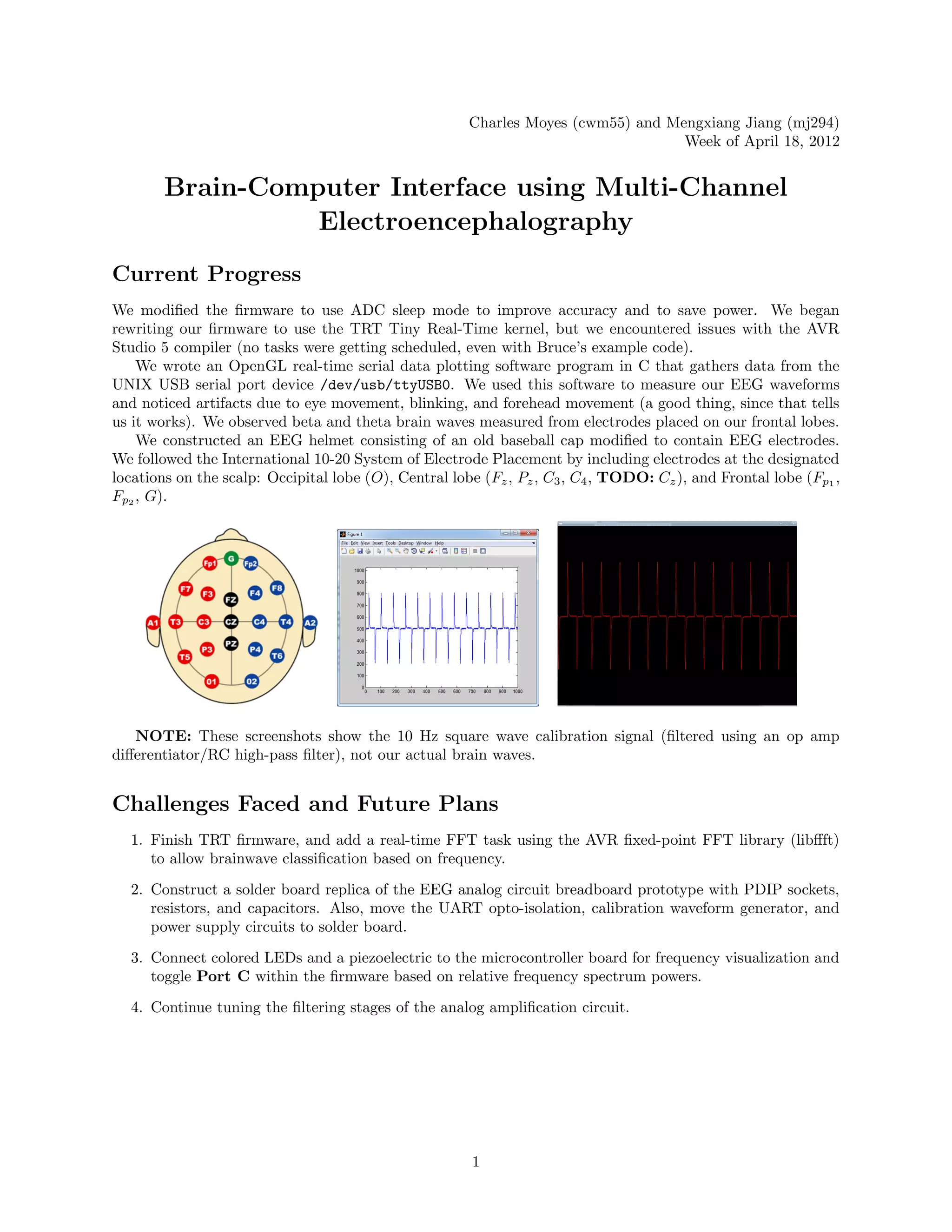

The document summarizes the current progress, challenges, and future plans of a project to create a brain-computer interface using multi-channel electroencephalography. It discusses modifying the firmware to improve accuracy and save power, constructing an EEG helmet with electrodes in standard positions, observing beta and theta brain waves, and facing issues with the real-time kernel. It also outlines plans to finish the firmware, construct a solder board, connect LEDs and a piezo for frequency visualization, and continue tuning the analog circuit.


