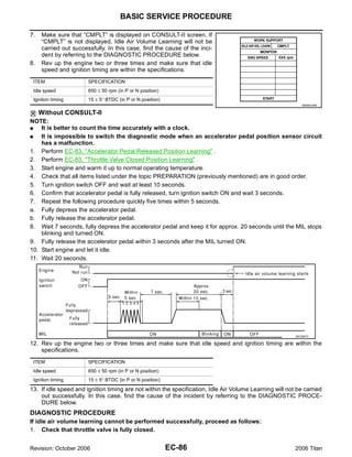
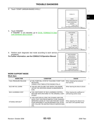
1. The document provides technical information about the engine control system for a vehicle, including diagnostic trouble codes (DTCs), testing procedures, component descriptions, and wiring diagrams.
2. It describes the various engine control systems such as the multiport fuel injection system, electronic ignition system, air conditioning cut control, and lists DTCs related to sensors like the mass air flow sensor and oxygen sensors.
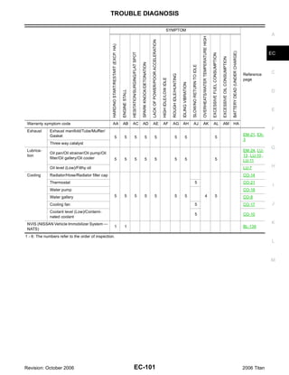
3. The document provides troubleshooting guides for technicians to diagnose issues, with sections on basic inspection, DTC inspection priority, symptom matrix, sensor reference values, and procedures for checking individual components.


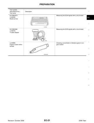


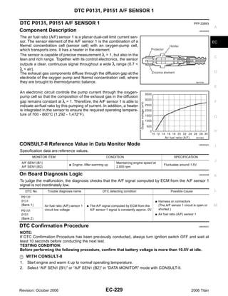
![ON BOARD REFUELING VAPOR RECOVERY (ORVR)
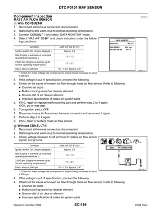
Component Inspection UBS00NA2
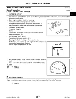
REFUELING EVAP VAPOR CUT VALVE A
With CONSULT-II
1. Remove fuel tank. Refer to FL-11, "FUEL TANK" .
2. Drain fuel from the tank as follows: EC
a. Remove fuel feed hose located on the fuel gauge retainer.
b. Connect a spare fuel hose, one side to fuel gauge retainer where the hose was removed and the other
side to a fuel container. C
c. Drain fuel using “FUEL PUMP RELAY” in “ACTIVE TEST” mode with CONSULT-II.
3. Check refueling EVAP vapor cut valve for being stuck to close as follows.
D
Blow air into the refueling EVAP vapor cut valve (from the end of EVAP/ORVR line hose), and check that
the air flows freely into the tank.
4. Check refueling EVAP vapor cut valve for being stuck to open as follows.
E
a. Connect vacuum pump to hose end.
b. Remove fuel gauge retainer with fuel gauge unit.
Always replace O-ring with new one.
F
c. Put fuel tank upside down.
d. Apply vacuum pressure to hose end [−13.3 kPa (−100 mmHg, −3.94 inHg)] with fuel gauge retainer
remaining open and check that the pressure is applicable.
G
H
I
J
K
BBIA0401E
L
Without CONSULT-II
1. Remove fuel tank. Refer to FL-11, "FUEL TANK" .
M
2. Drain fuel from the tank as follows:
a. Remove fuel gauge retainer.
b. Drain fuel from the tank using a handy pump into a fuel container.
3. Check refueling EVAP vapor cut valve for being stuck to close as follows.
Blow air into the refueling EVAP vapor cut valve (from the end of EVAP/ORVR line hose), and check that
the air flows freely into the tank.
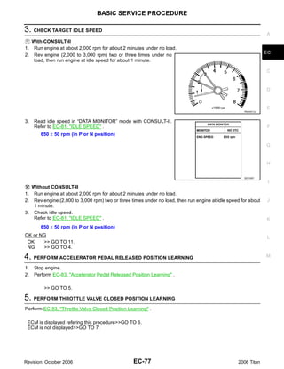
4. Check refueling EVAP vapor cut valve for being stuck to open as follows.
a. Connect vacuum pump to hose end.
b. Remove fuel gauge retainer with fuel gauge unit.
Always replace O-ring with new one.
c. Put fuel tank upside down.
Revision: October 2006 EC-43 2006 Titan](https://image.slidesharecdn.com/ec-110402131317-phpapp02/85/Ec-43-320.jpg)
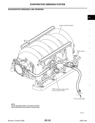
![ON BOARD REFUELING VAPOR RECOVERY (ORVR)
d. Apply vacuum pressure to hose end [−13.3 kPa (−100 mmHg, −3.94 inHg)] with fuel gauge retainer
remaining open and check that the pressure is applicable.
BBIA0401E
Revision: October 2006 EC-44 2006 Titan](https://image.slidesharecdn.com/ec-110402131317-phpapp02/85/Ec-44-320.jpg)


![ON BOARD DIAGNOSTIC (OBD) SYSTEM
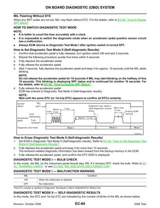
How to Read DTC and 1st Trip DTC
DTC and 1st trip DTC can be read by the following methods. A
With CONSULT-II
With GST
CONSULT-II or GST (Generic Scan Tool) Examples: P0340, P0850, P1148, etc. EC
These DTCs are prescribed by SAE J2012.
(CONSULT-II also displays the malfunctioning component or system.)
No Tools C
The number of blinks of the MIL in the Diagnostic Test Mode II (Self-Diagnostic Results) indicates the DTC.
Example: 0340, 0850, 1148, etc.
These DTCs are controlled by NISSAN.
D
G 1st trip DTC No. is the same as DTC No.
G Output of a DTC indicates a malfunction. However, GST or the Diagnostic Test Mode II do not indi-
cate whether the malfunction is still occurring or has occurred in the past and has returned to nor-
mal. CONSULT-II can identify malfunction status as shown below. Therefore, using CONSULT-II (if E
available) is recommended.
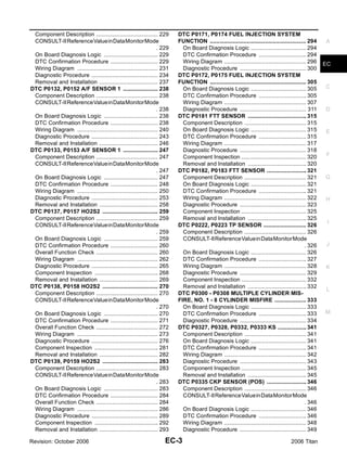
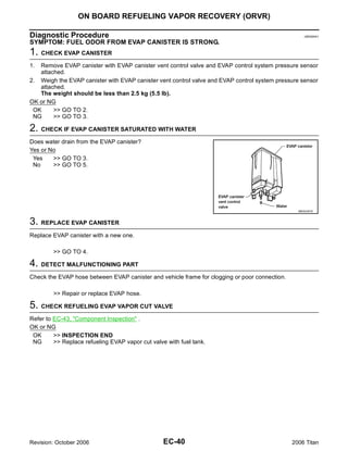
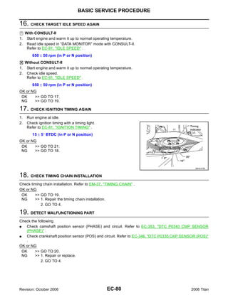
A sample of CONSULT-II display for DTC and 1st trip DTC is shown below. DTC or 1st trip DTC of a malfunc-
tion is displayed in SELF-DIAGNOSTIC RESULTS mode of CONSULT-II. Time data indicates how many times F
the vehicle was driven after the last detection of a DTC.
If the DTC is being detected currently, the time data will be [0].
If a 1st trip DTC is stored in the ECM, the time data will be [1t]. G
H
I
J
PBIB0911E
FREEZE FRAME DATA AND 1ST TRIP FREEZE FRAME DATA
The ECM records the driving conditions such as fuel system status, calculated load value, engine coolant tem- K
perature, short term fuel trim, long term fuel trim, engine speed, vehicle speed, absolute throttle position, base
fuel schedule and intake air temperature at the moment a malfunction is detected.
Data which are stored in the ECM memory, along with the 1st trip DTC, are called 1st trip freeze frame data. L
The data, stored together with the DTC data, are called freeze frame data and displayed on CONSULT-II or
GST. The 1st trip freeze frame data can only be displayed on the CONSULT-II screen, not on the GST. For
details, see EC-124, "Freeze Frame Data and 1st Trip Freeze Frame Data" .
Only one set of freeze frame data (either 1st trip freeze frame data or freeze frame data) can be stored in the M
ECM. 1st trip freeze frame data is stored in the ECM memory along with the 1st trip DTC. There is no priority
for 1st trip freeze frame data and it is updated each time a different 1st trip DTC is detected. However, once
freeze frame data (2nd trip detection/MIL on) is stored in the ECM memory, 1st trip freeze frame data is no
longer stored. Remember, only one set of freeze frame data can be stored in the ECM. The ECM has the fol-
lowing priorities to update the data.
Priority Items
Freeze frame data Misfire — DTC: P0300 - P0308
1
Fuel Injection System Function — DTC: P0171, P0172, P0174, P0175
2 Except the above items (Includes A/T related items)
3 1st trip freeze frame data
For example, the EGR malfunction (Priority: 2) was detected and the freeze frame data was stored in the 2nd
trip. After that when the misfire (Priority: 1) is detected in another trip, the freeze frame data will be updated
from the EGR malfunction to the misfire. The 1st trip freeze frame data is updated each time a different mal-
function is detected. There is no priority for 1st trip freeze frame data. However, once freeze frame data is
stored in the ECM memory, 1st trip freeze data is no longer stored (because only one freeze frame data or 1st
Revision: October 2006 EC-53 2006 Titan](https://image.slidesharecdn.com/ec-110402131317-phpapp02/85/Ec-53-320.jpg)


![ON BOARD DIAGNOSTIC (OBD) SYSTEM
G The time required for each diagnosis varies with road surface conditions, weather, altitude, individual driv-
ing habits, etc. A
Zone A refers to the range where the time, required for the diagnosis under normal conditions*, is the
shortest.
Zone B refers to the range where the diagnosis can still be performed if the diagnosis is not completed
EC
within zone A.
*: Normal conditions refer to the following:
G Sea level
C
G Flat road
G Ambient air temperature: 20 - 30°C (68 - 86°F)
G Diagnosis is performed as quickly as possible under normal conditions. D
Under different conditions [For example: ambient air temperature other than 20 - 30°C (68 - 86°F)], diag-
nosis may also be performed.
Pattern 1: E
G The engine is started at the engine coolant temperature of −10 to 35°C (14 to 95°F)
(where the voltage between the ECM terminal 73 and ground is 3.0 - 4.3V).
G The engine must be operated at idle speed until the engine coolant temperature is greater than F
70°C (158°F) (where the voltage between the ECM terminal 73 and ground is lower than 1.4V).
G The engine is started at the fuel tank temperature of warmer than 0°C (32°F) (where the voltage
between the ECM terminal 107 and ground is less than 4.1V).
G
Pattern 2:
G When steady-state driving is performed again even after it is interrupted, each diagnosis can be con-
ducted. In this case, the time required for diagnosis may be extended. H
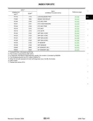
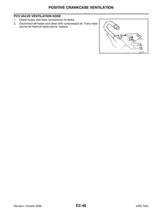
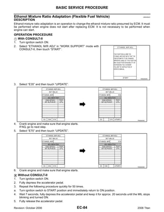
Pattern 3:
G Operate vehicle following the driving pattern shown in the figure.
G Release the accelerator pedal during decelerating vehicle speed I
from 90 km/h (56 MPH) to 0 km/h (0 MPH).
Pattern 4:
G The accelerator pedal must be held very steady during steady- J
state driving.
G If the accelerator pedal is moved, the test must be conducted all
over again. K
*1: Depress the accelerator pedal until vehicle speed is 90 km/h (56
MPH), then release the accelerator pedal and keep it released for PBIB2244E
more than 10 seconds. Depress the accelerator pedal until vehicle L
speed is 90 km/h (56 MPH) again.
*2: Checking the vehicle speed with GST is advised.
M
Suggested Transmission Gear Position
Set the selector lever in the D position with the overdrive switch turned ON.
Revision: October 2006 EC-59 2006 Titan](https://image.slidesharecdn.com/ec-110402131317-phpapp02/85/Ec-59-320.jpg)

![ON BOARD DIAGNOSTIC (OBD) SYSTEM
Test value (GST display)
Item Self-diagnostic test item DTC Test limit Conversion A
TID CID
P0032 57H 10H Max. 5 mV
Air fuel ratio (A/F) sensor 1 heater (Bank 1)
P0031 58H 90H Min. 5 mV EC
P0052 59H 11H Max. 5 mV
Air fuel ratio (A/F) sensor 1 heater (Bank 2)
HO2S P0051 5AH 91H Min. 5 mV
HEATER P0038 2DH 0AH Max. 20 mV C
Heated oxygen sensor 2 heater (Bank 1)
P0037 2EH 8AH Min. 20 mV
P0058 2FH 0BH Max. 20 mV
Heated oxygen sensor 2 heater (Bank 2) D
P0057 30H 8BH Min. 20 mV
HOW TO ERASE EMISSION-RELATED DIAGNOSTIC INFORMATION
E
How to Erase DTC
WITH CONSULT-II
The emission related diagnostic information in the ECM can be erased by selecting “ERASE” in the “SELF-
DIAG RESULTS” mode with CONSULT-II. F
If DTCs are displayed for both ECM and TCM (Transmission control module), they need to be erased individu-
ally from the ECM and TCM (Transmission control module).
NOTE: G
If the DTC is not for A/T related items (see EC-8, "INDEX FOR DTC" ), skip steps 2 through 4.
1. If the ignition switch stays ON after repair work, be sure to turn ignition switch OFF once. Wait at least 10
seconds and then turn it ON (engine stopped) again. H
2. Turn CONSULT-II ON and touch “A/T”.
3. Touch “SELF-DIAG RESULTS”.
4. Touch “ERASE”. [The DTC in the TCM (Transmission control module) will be erased.] Then touch “BACK” I
twice.
5. Touch “ENGINE”.
J
6. Touch “SELF-DIAG RESULTS”.
7. Touch “ERASE”. (The DTC in the ECM will be erased.)
K
L
M
Revision: October 2006 EC-61 2006 Titan](https://image.slidesharecdn.com/ec-110402131317-phpapp02/85/Ec-61-320.jpg)


![ON BOARD DIAGNOSTIC (OBD) SYSTEM
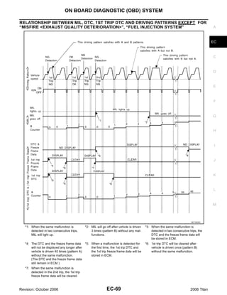
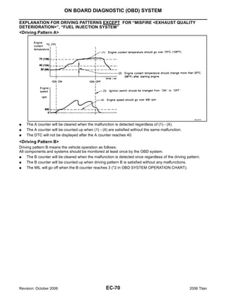
EXPLANATION FOR DRIVING PATTERNS FOR “MISFIRE <EXHAUST QUALITY DETERIORA-
TION>”, “FUEL INJECTION SYSTEM”
<Driving Pattern B>
Driving pattern B means the vehicle operation as follows:
All components and systems should be monitored at least once by the OBD system.
G The B counter will be cleared when the malfunction is detected once regardless of the driving pattern.
G The B counter will be counted up when driving pattern B is satisfied without any malfunction.
G The MIL will go off when the B counter reaches 3. (*2 in “OBD SYSTEM OPERATION CHART”)
<Driving Pattern C>
Driving pattern C means the vehicle operation as follows:
The following conditions should be satisfied at the same time:
Engine speed: (Engine speed in the freeze frame data) ±375 rpm
Calculated load value: (Calculated load value in the freeze frame data) x (1±0.1) [%]
Engine coolant temperature (T) condition:
G When the freeze frame data shows lower than 70°C (158°F), T should be lower than 70°C (158°F).
G When the freeze frame data shows higher than or equal to 70°C (158°F), T should be higher than or equal
to 70°C (158°F).
Example:
If the stored freeze frame data is as follows:
Engine speed: 850 rpm, Calculated load value: 30%, Engine coolant temperature: 80°C (176°F)
To be satisfied with driving pattern C, the vehicle should run under the following conditions:
Engine speed: 475 - 1,225 rpm, Calculated load value: 27 - 33%, Engine coolant temperature: more than 70°C
(158°F)
G The C counter will be cleared when the malfunction is detected regardless of vehicle conditions above.
G The C counter will be counted up when vehicle conditions above is satisfied without the same malfunction.
G The DTC will not be displayed after C counter reaches 80.
G The 1st trip DTC will be cleared when C counter is counted once without the same malfunction after DTC
is stored in ECM.
Revision: October 2006 EC-68 2006 Titan](https://image.slidesharecdn.com/ec-110402131317-phpapp02/85/Ec-68-320.jpg)


![TROUBLE DIAGNOSIS
ECM Harness Connector Terminal Layout UBS00NAR
A
EC
C
MBIB0045E D
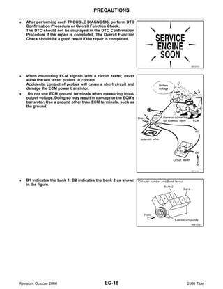
ECM Terminals and Reference Value UBS00NAS
PREPARATION E
1. ECM is located in the engine room passenger side behind bat-
tery.
2. Remove ECM harness connector.
F
G
H
BBIA0386E
3. When disconnecting ECM harness connector, loosen it with
levers as far as they will go as shown in the figure. I
4. Connect a break-out box (SST) and Y-cable adapter (SST)
between the ECM and ECM harness connector.
G Use extreme care not to touch 2 pins at one time.
J
G Data is for comparison and may not be exact.
K
BBIA0387E
L
ECM INSPECTION TABLE
Specification data are reference values and are measured between each terminal and ground.
Pulse signal is measured by CONSULT-II. M
CAUTION:
Do not use ECM ground terminals when measuring input/output voltage. Doing so may result in dam-
age to the ECMs transistor. Use a ground other than ECM terminals, such as the ground.
TER-
WIRE
MINAL ITEM CONDITION DATA (DC Voltage)
COLOR
NO.
[Engine is running]
1 B ECM ground Body ground
G Idle speed
Approximately 5V
[Engine is running]
A/F sensor 1 heater
2 O/B G Warm-up condition
(bank 1)
G Idle speed
PBIB1584E
Revision: October 2006 EC-111 2006 Titan](https://image.slidesharecdn.com/ec-110402131317-phpapp02/85/Ec-111-320.jpg)
![TROUBLE DIAGNOSIS
TER-
WIRE
MINAL ITEM CONDITION DATA (DC Voltage)
COLOR
NO.
Throttle control motor relay BATTERY VOLTAGE
3 L [Ignition switch: ON]
power supply (11 - 14V)
0 - 14V
[Ignition switch: ON]
G Engine: Stopped
4 L/W Throttle control motor (Close)
G Selector lever: D
G Accelerator pedal: Fully released
PBIB1104E
0 - 14V
[Ignition switch: ON]
G Engine: Stopped
5 L/B Throttle control motor (Open)
G Selector lever: D
G Accelerator pedal: Fully depressed
PBIB1105E
[Engine is running]
G Engine speed: Below 3,600 rpm after the
following conditions are met.
– Engine: After warming up 0 - 1.0V
– Keeping the engine speed between 3,500
Heated oxygen sensor 2 and 4,000 rpm for 1 minute and at idle for 1
6 GR
heater (bank 1) minute under no load
[Ignition switch: ON]
G Engine: Stopped BATTERY VOLTAGE
[Engine is running] (11 - 14V)
G Engine speed: Above 3,600 rpm
[Engine is running]
0.5 - 4.5V
Power steering pressure sen- G Steering wheel: Being turned
12 R
sor [Engine is running]
0.4 - 0.8V
G Steering wheel: Not being turned
Approximately 10V
[Engine is running]
G Warm-up condition
G Idle speed
NOTE:
The pulse cycle changes depending on rpm
at idle
PBIB1041E
Crankshaft position sensor
13 O
(POS)
Approximately 10V
[Engine is running]
G Engine speed: 2,000 rpm
PBIB1042E
Revision: October 2006 EC-112 2006 Titan](https://image.slidesharecdn.com/ec-110402131317-phpapp02/85/Ec-112-320.jpg)
![TROUBLE DIAGNOSIS
TER-
WIRE
MINAL ITEM CONDITION DATA (DC Voltage) A
COLOR
NO.
1.0 - 4.0V
[Engine is running] EC
G Warm-up condition
G Idle speed
NOTE: C
The pulse cycle changes depending on rpm
at idle
Camshaft position sensor PBIB1039E
14 Y D
(PHASE)
1.0 - 4.0V
[Engine is running] E
G Engine speed: 2,000 rpm
F
PBIB1040E
[Engine is running]
15 W Knock sensor (bank 1) Approximately 2.5V
G Idle speed G
16 BR/R Approximately 3.1V
[Engine is running]
35 BR/G Approximately 2.6V
A/F sensor 1 (bank 1) G Warm-up condition H
56 LG/B Approximately 2.3V
G Idle speed
75 P/B Approximately 2.3V
BATTERY VOLTAGE
I
[Engine is running] (11 - 14V)
G Warm-up condition
G Idle speed J
NOTE:
The pulse cycle changes depending on rpm
at idle
21 O/L Fuel injector No. 5 K
22 BR Fuel injector No. 3 SEC984C
23 GR/W Fuel injector No. 1 BATTERY VOLTAGE
44 O Fuel injector No. 7
(11 - 14V) L
[Engine is running]
G Warm-up condition
G Engine speed: 2,000 rpm
M
SEC985C
Approximately 5V
[Engine is running]
A/F sensor 1 heater
24 BR/W G Warm-up condition
(bank 2)
G Idle speed
PBIB1584E
Revision: October 2006 EC-113 2006 Titan](https://image.slidesharecdn.com/ec-110402131317-phpapp02/85/Ec-113-320.jpg)
![TROUBLE DIAGNOSIS
TER-
WIRE
MINAL ITEM CONDITION DATA (DC Voltage)
COLOR
NO.
[Engine is running]
G Engine speed: Below 3,600 rpm after the
following conditions are met.
– Engine: After warming up 0 - 1.0V
– Keeping the engine speed between 3,500
Heated oxygen sensor 2 and 4,000 rpm for 1 minute and at idle for 1
25 O/G
heater (bank 2) minute under no load
[Ignition switch: ON]
G Engine: Stopped BATTERY VOLTAGE
[Engine is running] (11 - 14V)
G Engine speed: Above 3,600 rpm
EVAP control system pres-
32 L [Ignition switch: ON] Approximately 1.8 - 4.8V
sure sensor
Approximately 0 - 4.8V
34 R/B Intake air temperature sensor [Engine is running] Output voltage varies with intake
air temperature.
[Engine is running]
36 W Knock sensor (bank 2) Approximately 2.5V
G Idle speed
[Ignition switch: ON]
G More than a few seconds after turning igni- Approximately 0V
tion switch ON
[Ignition switch: ON]
Fuel pump control module
38 L G For a few seconds after turning ignition
(FPCM) check
switch ON
4 - 6V
[Engine is running]
G Warm-up condition
G Idle speed
[When cranking engine] 0 - 0.5V
Fuel pump control module [Engine is running]
39 L/Y
(FPCM) G Warm-up condition 8 - 12V
G Idle speed
BATTERY VOLTAGE
[Engine is running] (11 - 14V)
G Warm-up condition
G Idle speed
NOTE:
The pulse cycle changes depending on rpm
at idle
40 Y/G Fuel injector No. 6
41 P Fuel injector No. 4 SEC984C
42 L Fuel injector No. 2 BATTERY VOLTAGE
63 G Fuel injector No. 8
(11 - 14V)
[Engine is running]
G Warm-up condition
G Engine speed: 2,000 rpm
SEC985C
Revision: October 2006 EC-114 2006 Titan](https://image.slidesharecdn.com/ec-110402131317-phpapp02/85/Ec-114-320.jpg)
![TROUBLE DIAGNOSIS
TER-
WIRE
MINAL ITEM CONDITION DATA (DC Voltage) A
COLOR
NO.
BATTERY VOLTAGE
(11 - 14V) EC
[Engine is running]
G Idle speed
G Accelerator pedal: Not depressed even C
slightly, after engine starting
EVAP canister purge volume SEC990C D
45 L/Y
control solenoid valve BATTERY VOLTAGE
(11 - 14V)
E
[Engine is running]
G Engine speed: About 2,000 rpm (More than
100 seconds after starting engine)
F
SEC991C
G
0 - 0.3V
[Engine is running]
G Warm-up condition
G Idle speed H
NOTE:
The pulse cycle changes depending on rpm
46 L/R Ignition signal No. 7 at idle I
60 GR/R Ignition signal No. 5 SEC986C
61 O/W Ignition signal No. 3
0.1 - 0.6V
62 Y/R Ignition signal No. 1
J
[Engine is running]
G Warm-up condition
G Engine speed: 2,500 rpm K
SEC987C
Sensor power supply L
47 Y [Ignition switch: ON] Approximately 5V
(Throttle position sensor)
Sensor power supply
48 SB (EVAP control system pres- [Ignition switch: ON] Approximately 5V M
sure sensor)
Sensor power supply
49 R/Y [Ignition switch: ON] Approximately 5V
(Refrigerant pressure sensor)
[Ignition switch: ON]
G Engine: Stopped
More than 0.36V
G Selector lever: D
G Accelerator pedal: Fully released
50 B Throttle position sensor 1
[Ignition switch: ON]
G Engine: Stopped
Less than 4.75V
G Selector lever: D
G Accelerator pedal: Fully depressed
Revision: October 2006 EC-115 2006 Titan](https://image.slidesharecdn.com/ec-110402131317-phpapp02/85/Ec-115-320.jpg)
![TROUBLE DIAGNOSIS
TER-
WIRE
MINAL ITEM CONDITION DATA (DC Voltage)
COLOR
NO.
[Engine is running]
G Warm-up condition 1.0 - 1.3V
G Idle speed
51 W Mass air flow sensor
[Engine is running]
G Warm-up condition 1.7 - 2.1V
G Engine speed: 2,500 rpm
[Engine is running]
G Revving engine from idle to 3,000 rpm
quickly after the following conditions are
Heated oxygen sensor 2 met.
55 R 0 - Approximately 1.0V
(bank 1) – Engine: After warming up
– Keeping the engine speed between 3,500
and 4,000 rpm for 1 minute and at idle for 1
minute under no load
57 L/P Approximately 2.6V
[Engine is running]
58 GR/G Approximately 2.3V
A/F sensor 1 (bank 2) G Warm-up condition
76 G/L Approximately 3.1V
G Idle speed
77 BR/B Approximately 2.3V
0 - 0.3V
[Engine is running]
G Warm-up condition
G Idle speed
NOTE:
The pulse cycle changes depending on rpm
65 G/R Ignition signal No. 8 at idle
79 V/W Ignition signal No. 6 SEC986C
80 W/R Ignition signal No. 4
0.1 - 0.6V
81 W/G Ignition signal No. 2
[Engine is running]
G Warm-up condition
G Engine speed: 2,500 rpm
SEC987C
[Engine is running]
Sensor ground
66 R G Warm-up condition Approximately 0V
(Throttle position sensor)
G Idle speed
[Engine is running]
67 B Sensor ground G Warm-up condition Approximately 0V
G Idle speed
Sensor power supply
68 W/L [Ignition switch: ON] Approximately 5V
(PSP sensor)
[Ignition switch: ON]
G Engine: Stopped
Less than 4.75V
G Selector lever: D
G Accelerator pedal: Fully released
69 W Throttle position sensor 2
[Ignition switch: ON]
G Engine: Stopped
More than 0.36V
G Selector lever: D
G Accelerator pedal: Fully depressed
Revision: October 2006 EC-116 2006 Titan](https://image.slidesharecdn.com/ec-110402131317-phpapp02/85/Ec-116-320.jpg)
![TROUBLE DIAGNOSIS
TER-
WIRE
MINAL ITEM CONDITION DATA (DC Voltage) A
COLOR
NO.
[Engine is running]
G Warm-up condition EC
70 B/W Refrigerant pressure sensor 1.0 - 4.0V
G Both A/C switch and blower switch: ON
(Compressor: Operates.)
Approximately 0 - 4.8V C
Engine coolant temperature
73 Y/B [Engine is running] Output voltage varies with
sensor
engine coolant temperature.
[Engine is running] D
G Revving engine from idle to 3,000 rpm
quickly after the following conditions are
Heated oxygen sensor 2 met.
74 L 0 - Approximately 1.0V E
(bank 2) – Engine: After warming up
– Keeping the engine speed between 3,500
and 4,000 rpm for 1 minute and at idle for 1
minute under no load F
[Engine is running]
Sensor ground
78 B/W G Warm-up condition Approximately 0V
(Heated oxygen sensor 2)
G Idle speed G
[Engine is running]
Sensor ground
82 B/R G Warm-up condition Approximately 0V
(APP sensor 1) H
G Idle speed
[Engine is running]
Sensor ground
83 G/W G Warm-up condition Approximately 0V
(APP sensor 2) I
G Idle speed
[Ignition switch: ON] Approximately 5V - Battery volt-
85 G/W Data link connector
G CONSULT-II or GST: Disconnected age (11 - 14V) J
Approximately 1.1 - 2.3V
86 P CAN communication line [Ignition switch: ON] Output voltage varies with the
communication status
K
Sensor power supply
90 L [Ignition switch: ON] Approximately 5V
(APP sensor 1)
Sensor power supply L
91 W/R [Ignition switch: ON] Approximately 5V
(APP sensor 2)
Approximately 2.6 - 3.2V
94 L CAN communication line [Ignition switch: ON] Output voltage varies with the
communication status. M
[Ignition switch: ON]
G Engine: Stopped 0.25 - 0.50V
Accelerator pedal position G Accelerator pedal: Fully released
98 G/R
sensor 2 [Ignition switch: ON]
G Engine: Stopped 2.0 - 2.5V
G Accelerator pedal: Fully depressed
Revision: October 2006 EC-117 2006 Titan](https://image.slidesharecdn.com/ec-110402131317-phpapp02/85/Ec-117-320.jpg)
![TROUBLE DIAGNOSIS
TER-
WIRE
MINAL ITEM CONDITION DATA (DC Voltage)
COLOR
NO.
[Ignition switch: ON]
Approximately 4V
G ASCD steering switch: OFF
[Ignition switch: ON]
Approximately 0V
G MAIN switch: Pressed
[Ignition switch: ON]
99 G/Y ASCD steering switch Approximately 1V
G CANCEL switch: Pressed
[Ignition switch: ON]
Approximately 3V
G RESUME/ACCELERATE switch: Pressed
[Ignition switch: ON]
Approximately 2V
G SET/COAST switch: Pressed
[Ignition switch: OFF]
Approximately 0V
G Brake pedal: Fully released
101 R/W Stop lamp switch
[Ignition switch: OFF] BATTERY VOLTAGE
G Brake pedal: Slightly depressed (11 - 14V)
[Ignition switch: ON]
Approximately 0V
G Selector lever: P or N
102 GR/R PNP switch
[Ignition switch: ON] BATTERY VOLTAGE
G Except the above gear position (11 - 14V)
BATTERY VOLTAGE
[Ignition switch: OFF]
104 O Throttle control motor relay (11 - 14V)
[Ignition switch: ON] 0 - 1.0V
[Ignition switch: ON]
G Engine: Stopped 0.5 - 1.0V
Accelerator pedal position G Accelerator pedal: Fully released
106 BR/W
sensor 1 [Ignition switch: ON]
G Engine: Stopped 4.2 - 4.8V
G Accelerator pedal: Fully depressed
Approximately 0 - 4.8V
107 V/R Fuel tank temperature sensor [Engine is running] Output voltage varies with fuel
tank temperature.
[Ignition switch: ON]
Approximately 0V
G Brake pedal: Slightly depressed
108 BR/W ASCD brake switch
[Ignition switch: ON] BATTERY VOLTAGE
G Brake pedal: Fully released (11 - 14V)
[Ignition switch: OFF] 0V
109 L/W Ignition switch BATTERY VOLTAGE
[Ignition switch: ON]
(11 - 14V)
[Engine is running]
[Ignition switch: OFF]
0 - 1.5V
G For a few seconds after turning ignition
ECM relay switch OFF
111 W/B
(Self shut-off)
[Ignition switch: OFF]
BATTERY VOLTAGE
G More than a few seconds after turning igni- (11 - 14V)
tion switch OFF
Revision: October 2006 EC-118 2006 Titan](https://image.slidesharecdn.com/ec-110402131317-phpapp02/85/Ec-118-320.jpg)
![TROUBLE DIAGNOSIS
TER-
WIRE
MINAL ITEM CONDITION DATA (DC Voltage) A
COLOR
NO.
[Ignition switch: ON]
G For 1 second after turning ignition switch EC
0 - 1.5V
ON
113 GR Fuel pump relay [Engine is running]
[Ignition switch: ON] C
BATTERY VOLTAGE
G More than 1 second after turning ignition (11 - 14V)
switch ON
115 B [Engine is running] D
ECM ground Body ground
116 B/W G Idle speed
EVAP canister vent control BATTERY VOLTAGE
117 L/Y [Ignition switch: ON]
valve (11 - 14V) E
119 BR BATTERY VOLTAGE
Power supply for ECM [Ignition switch: ON]
120 BR (11 - 14V)
Power supply for ECM BATTERY VOLTAGE F
121 W [Ignition switch: OFF]
(Back-up) (11 - 14V)
: Average voltage for pulse signal (Actual pulse signal can be confirmed by oscilloscope.)
G
H
I
J
K
L
M
Revision: October 2006 EC-119 2006 Titan](https://image.slidesharecdn.com/ec-110402131317-phpapp02/85/Ec-119-320.jpg)


![TROUBLE DIAGNOSIS
WORK ITEM CONDITION USAGE
EVAP SYSTEM CLOSE CLOSE THE EVAP CANISTER VENT CONTROL VALVE IN When detecting EVAP vapor leak
ORDER TO MAKE EVAP SYSTEM CLOSE UNDER THE point of EVAP system
FOLLOWING CONDITIONS.
G IGN SW ON
G ENGINE NOT RUNNING
G AMBIENT TEMPERATURE IS ABOVE 0°C (32°F).
G NO VACUUM AND NO HIGH PRESSURE IN EVAP SYS-
TEM
G FUEL TANK TEMP. IS MORE THAN 0°C (32°F).
G WITHIN 10 MINUTES AFTER STARTING “EVAP SYS-
TEM CLOSE”
G WHEN TRYING TO EXECUTE “EVAP SYSTEM CLOSE”
UNDER THE CONDITION EXCEPT ABOVE, CONSULT-
II WILL DISCONTINUE IT AND DISPLAY APPROPRI-
ATE INSTRUCTION.
NOTE:
WHEN STARTING ENGINE, CONSULT-II MAY DISPLAY
“BATTERY VOLTAGE IS LOW. CHARGE BATTERY”,
EVEN IN USING CHARGED BATTERY.
VIN REGISTRATION G IN THIS MODE, VIN IS REGISTERED IN ECM When registering VIN in ECM
TARGET IDLE RPM ADJ*1 G IDLE CONDITION When setting target idle speed
TARGET IGN TIM ADJ*1 G IDLE CONDITION When adjusting target ignition tim-
ing
*1: This function is not necessary in the usual service procedure.
*2: For Flexible Fuel Vehicle
SELF-DIAG RESULTS MODE
Self Diagnostic Item
Regarding items of DTC and 1st trip DTC, refer to EC-49, "EMISSION-RELATED DIAGNOSTIC INFORMA-
TION ITEMS" .
Freeze Frame Data and 1st Trip Freeze Frame Data
Freeze frame data
Description
item*
DIAG TROUBLE
G The engine control component part/control system has a trouble code, it is displayed as PXXXX. (Refer to
CODE
EC-8, "INDEX FOR DTC" .)
[PXXXX]
FUEL SYS-B1 G “Fuel injection system status” at the moment a malfunction is detected is displayed.
G One mode in the following is displayed.
Mode2: Open loop due to detected system malfunction
FUEL SYS-B2 Mode3: Open loop due to driving conditions (power enrichment, deceleration enleanment)
Mode4: Closed loop - using oxygen sensor(s) as feedback for fuel control
Mode5: Open loop - has not yet satisfied condition to go to closed loop
CAL/LD VALUE [%] G The calculated load value at the moment a malfunction is detected is displayed.
COOLANT TEMP
G The engine coolant temperature at the moment a malfunction is detected is displayed.
[°C] or [°F]
L-FUEL TRM-B1 [%] G “Long-term fuel trim” at the moment a malfunction is detected is displayed.
G The long-term fuel trim indicates much more gradual feedback compensation to the base fuel schedule
L-FUEL TRM-B2 [%]
than short-term fuel trim.
S-FUEL TRM-B1 [%] G “Short-term fuel trim” at the moment a malfunction is detected is displayed.
G The short-term fuel trim indicates dynamic or instantaneous feedback compensation to the base fuel
S-FUEL TRM-B2 [%] schedule.
ENGINE SPEED
G The engine speed at the moment a malfunction is detected is displayed.
[rpm]
Revision: October 2006 EC-124 2006 Titan](https://image.slidesharecdn.com/ec-110402131317-phpapp02/85/Ec-124-320.jpg)
![TROUBLE DIAGNOSIS
Freeze frame data
Description
item* A
VEHICL SPEED
G The vehicle speed at the moment a malfunction is detected is displayed.
[km/h] or [mph]
ABSOL TH-P/S EC
G The throttle valve opening at the moment a malfunction is detected is displayed.
[%]
B/FUEL SCHDL
G The base fuel schedule at the moment a malfunction is detected is displayed.
[msec] C
INT/A TEMP SE
G The intake air temperature at the moment a malfunction is detected is displayed.
[°C] or [°F]
*: The item is the same as that of 1st trip freeze frame data. D
DATA MONITOR MODE
Monitored Item E
×: Applicable
ECM
Monitored item MAIN
INPUT Description Remarks
[Unit] SIGNALS F
SIGNALS
G Accuracy becomes poor if engine speed
G Indicates the engine speed computed drops below the idle rpm.
from the signal of the crankshaft position
ENG SPEED [rpm] × × G If the signal is interrupted while the G
sensor (POS) and camshaft position
sensor (PHASE). engine is running, an abnormal value
may be indicated.
MAS A/F SE-B1 [V] × ×
G The signal voltage of the mass air flow G When the engine is stopped, a certain H
sensor is displayed. value is indicated.
G Base fuel schedule indicates the fuel
B/FUEL SCHDL injection pulse width programmed into
× I
[msec] ECM, prior to any learned on board cor-
rection.
A/F ALPHA-B1 [%] × G When the engine is stopped, a certain
G The mean value of the air-fuel ratio feed- value is indicated. J
back correction factor per cycle is indi-
A/F ALPHA-B2 [%] × cated. G This data also includes the data for the
air-fuel ratio learning control.
G When the engine coolant temperature K
G The engine coolant temperature (deter-
sensor is open or short-circuited, ECM
COOLAN TEMP/S mined by the signal voltage of the
× × enters fail-safe mode. The engine cool-
[°C] or [°F] engine coolant temperature sensor) is
ant temperature determined by the
displayed. L
ECM is displayed.
A/F SEN1 (B1) [V] × × G The A/F signal computed from the input
A/F SEN1 (B2) [V] × signal of the A/F sensor 1 is displayed.
M
HO2S2 (B1) [V] × G The signal voltage of the heated oxygen
HO2S2 (B2) [V] × sensor 2 is displayed.
HO2S2 MNTR (B1) G Display of heated oxygen sensor 2 sig-
×
[RICH/LEAN] nal:
RICH: means the amount of oxygen
after three way catalyst is relatively G When the engine is stopped, a certain
HO2S2 MNTR (B2) small. value is indicated.
× LEAN: means the amount of oxygen
[RICH/LEAN]
after three way catalyst is relatively
large.
G The vehicle speed computed from the
VHCL SPEED SE
× × vehicle speed signal sent from combina-
[km/h] or [mph]
tion meter is displayed.
BATTERY VOLT G The power supply voltage of ECM is dis-
× ×
[V] played.
Revision: October 2006 EC-125 2006 Titan](https://image.slidesharecdn.com/ec-110402131317-phpapp02/85/Ec-125-320.jpg)
![TROUBLE DIAGNOSIS
ECM
Monitored item MAIN
INPUT Description Remarks
[Unit] SIGNALS
SIGNALS
ACCEL SEN 1 [V] × × G ACCEL SEN 2 signal is converted by
G The accelerator pedal position sensor
ECM internally. Thus, it differs from
ACCEL SEN 2 [V] × signal voltage is displayed.
ECM terminal voltage signal.
THRTL SEN 1 [V] × × G THRTL SEN 2 signal is converted by
G The throttle position sensor signal volt-
ECM internally. Thus, it differs from
THRTL SEN 2 [V] × age is displayed.
ECM terminal voltage signal.
G The fuel temperature (determined by the
FUEL T/TMP SE
× signal voltage of the fuel tank tempera-
[°C] or [°F]
ture sensor) is displayed.
G The intake air temperature (determined
INT/A TEMP SE
× × by the signal voltage of the intake air
[°C] or [°F]
temperature sensor) is indicated.
EVAP SYS PRES G The signal voltage of EVAP control sys-
×
[V] tem pressure sensor is displayed.
FPCM DR VOLT G The voltage between fuel pump and
[V]* FPCM is displayed.
FUEL LEVEL SE G The signal voltage of the fuel level sen-
×
[V] sor is displayed.
G Indicates start signal status [ON/OFF]
START SIGNAL computed by the ECM according to the G After starting the engine, [OFF] is dis-
× ×
[ON/OFF] signals of engine speed and battery volt- played regardless of the starter signal.
age.
G Indicates idle position [ON/OFF] com-
CLSD THL POS
× × puted by ECM according to the acceler-
[ON/OFF]
ator pedal position sensor signal.
G Indicates [ON/OFF] condition of the air
AIR COND SIG
× × conditioner switch as determined by the
[ON/OFF]
air conditioner signal.
G Indicates [ON/OFF] condition from the
P/N POSI SW
× × park/neutral position (PNP) switch sig-
[ON/OFF]
nal.
G [ON/OFF] condition of the power steer-
PW/ST SIGNAL ing system (determined by the signal
× ×
[ON/OFF] voltage of the power steering pressure
sensor signal) is indicated.
G Indicates [ON/OFF] condition from the
LOAD SIGNAL electrical load signal.
× ×
[ON/OFF] ON: Lighting switch is in 2nd position.
OFF: Lighting switch is OFF.
IGNITION SW G Indicates [ON/OFF] condition from igni-
×
[ON/OFF] tion switch signal.
HEATER FAN SW G Indicates [ON/OFF] condition from
×
[ON/OFF] heater fan switch signal.
BRAKE SW G Indicates [ON/OFF] condition from the
×
[ON/OFF] stop lamp switch signal.
INJ PULSE-B1
× G Indicates the actual fuel injection pulse
[msec] G When the engine is stopped, a certain
width compensated by ECM according
INJ PULSE-B2 computed value is indicated.
to the input signals.
[msec]
IGN TIMING G Indicates the ignition timing computed G When the engine is stopped, a certain
×
[BTDC] by ECM according to the input signals. value is indicated.
G “Calculated load value” indicates the
CAL/LD VALUE [%] value of the current air flow divided by
peak air flow.
Revision: October 2006 EC-126 2006 Titan](https://image.slidesharecdn.com/ec-110402131317-phpapp02/85/Ec-126-320.jpg)
![TROUBLE DIAGNOSIS
ECM
Monitored item MAIN
INPUT Description Remarks A
[Unit] SIGNALS
SIGNALS
G Indicates the mass air flow computed by
MASS AIRFLOW
ECM according to the signal voltage of EC
[g·m/s]
the mass air flow sensor.
G Indicates the EVAP canister purge vol-
ume control solenoid valve control value
computed by the ECM according to the
C
PURG VOL C/V
[%] input signals.
G The opening becomes larger as the
value increases. D
G The air conditioner relay control condi-
AIR COND RLY
× tion (determined by ECM according to
[ON/OFF]
the input signals) is indicated. E
G Indicates the fuel pump relay control
FUEL PUMP RLY
× condition determined by ECM according
[ON/OFF]
to the input signals.
F
G The control condition of the fuel pump
FPCM control module (FPCM) (determined by
×
[HI/LOW]* the ECM according to the input signals)
is indicated. G
G The control condition of the EVAP canis-
ter vent control valve (determined by
VENT CONT/V ECM according to the input signals) is H
[ON/OFF] indicated.
ON: Closed
OFF: Open
G Indicates the throttle control motor relay I
THRTL RELAY
× control condition determined by the
[ON/OFF]
ECM according to the input signals.
G The control condition of the cooling fan J
(determined by ECM according to the
COOLING FAN
× input signals) is indicated.
[HI/OFF]
HI: High speed operation
OFF: Stop K
HO2S2 HTR (B1)
[ON/OFF] G Indicates [ON/OFF] condition of heated
oxygen sensor 2 heater determined by L
HO2S2 HTR (B2) ECM according to the input signals.
[ON/OFF]
G Indicates the engine speed computed
I/P PULLY SPD M
from the turbine revolution sensor sig-
[rpm]
nal.
VEHICLE SPEED G Indicates the vehicle speed computed
[km/h] or [MPH] from the revolution sensor signal.
G Display the condition of idle air volume
learning
IDL A/V LEARN YET: Idle Air Volume Learning has not
[YET/CMPLT] been performed yet.
CMPLT: Idle Air Volume Learning has
already been performed successfully.
TRVL AFTER MIL
G Distance traveled while MIL is activated.
[km] or [mile]
A/F S1 HTR (B1) G A/F sensor 1 heater control value com-
[%] puted by ECM according to the input sig-
nals.
A/F S1 HTR (B2) G The current flow to the heater becomes
[%]
larger as the value increases.
Revision: October 2006 EC-127 2006 Titan](https://image.slidesharecdn.com/ec-110402131317-phpapp02/85/Ec-127-320.jpg)
![TROUBLE DIAGNOSIS
ECM
Monitored item MAIN
INPUT Description Remarks
[Unit] SIGNALS
SIGNALS
AC PRESS SEN G The signal voltage from the refrigerant
[V] pressure sensor is displayed.
G The vehicle speed computed from the
VHCL SPEED SE
vehicle speed signal sent from combina-
[km/h] or [mph]
tion meter is displayed.
SET VHCL SPD
G The preset vehicle speed is displayed.
[km/h] or [mph]
MAIN SW G Indicates [ON/OFF] condition from MAIN
[ON/OFF] switch signal.
CANCEL SW G Indicates [ON/OFF] condition from CAN-
[ON/OFF] CEL switch signal.
RESUME/ACC SW G Indicates [ON/OFF] condition from
[ON/OFF] RESUME/ACCELERATE switch signal.
SET SW G Indicates [ON/OFF] condition from SET/
[ON/OFF] COAST switch signal.
BRAKE SW1 G Indicates [ON/OFF] condition from
[ON/OFF] ASCD brake switch signal.
BRAKE SW2 G Indicates [ON/OFF] condition of stop
[ON/OFF] lamp switch signal.
G Indicates the vehicle cruise condition.
NON: Vehicle speed is maintained at the
VHCL SPD CUT ASCD set speed.
[NON/CUT] CUT: Vehicle speed increased to exces-
sively high compared with the ASCD set
speed, and ASCD operation is cut off.
G Indicates the vehicle cruise condition.
NON: Vehicle speed is maintained at the
LO SPEED CUT ASCD set speed.
[NON/CUT] CUT: Vehicle speed decreased to exces-
sively low compared with the ASCD set
speed, and ASCD operation is cut off.
G Indicates [ON/OFF] condition of A/T O/D
AT OD MONITOR
according to the input signal from the
[ON/OFF]
TCM.
AT OD CANCEL G Indicates [ON/OFF] condition of A/T O/D
[ON/OFF] cancel signal sent from the TCM.
G Indicates [ON/OFF] condition of
CRUISE LAMP
CRUISE lamp determined by the ECM
[ON/OFF]
according to the input signals.
G Indicates [ON/OFF] condition of SET
SET LAMP
lamp determined by the ECM according
[ON/OFF]
to the input signals.
G Ethanol mixture ratio presumed by the
ETHANOL M/R
ECM according to the input signals is
[%]*
displayed.
Voltage [V]
Frequency [msec], G Only # is displayed if item is unable to
[Hz] or [%] be measured.
DUTY-HI G Voltage, frequency, duty cycle or pulse G Figures with #s are temporary ones.
width measured by the probe. They are the same figures as an actual
DUTY-LOW piece of data which was just previously
PLS WIDTH-HI measured.
PLS WIDTH-LOW
*: For Flexible Fuel Vehicle
Revision: October 2006 EC-128 2006 Titan](https://image.slidesharecdn.com/ec-110402131317-phpapp02/85/Ec-128-320.jpg)
![TROUBLE DIAGNOSIS
NOTE:
Any monitored item that does not match the vehicle being diagnosed is deleted from the display automatically. A
DATA MONITOR (SPEC) MODE
Monitored Item
EC
ECM
Monitored item MAIN
INPUT Description Remarks
[Unit] SIGNALS
SIGNALS
G Indicates the engine speed computed
C
from the signal of the crankshaft position
ENG SPEED [rpm] × ×
sensor (POS) and camshaft position
sensor (PHASE). D
G The signal voltage of the mass air flow G When engine is running specification
MAS A/F SE-B1 [V] × ×
sensor specification is displayed. range is indicated.
G Base fuel schedule indicates the fuel E
B/FUEL SCHDL injection pulse width programmed into G When engine is running specification
×
[msec] ECM, prior to any learned on board cor- range is indicated.
rection.
G When engine is running specification
F
G The mean value of the air-fuel ratio feed- range is indicated.
A/F ALPHA-B1 [%]
× back correction factor per cycle is indi-
A/F ALPHA-B2 [%] G This data also includes the data for
cated.
the air-fuel ratio learning control. G
NOTE:
Any monitored item that does not match the vehicle being diagnosed is deleted from the display automatically.
H
ACTIVE TEST MODE
Test Item
TEST ITEM CONDITION JUDGEMENT CHECK ITEM (REMEDY) I
G Engine: Return to the original G Harness and connectors
FUEL INJEC- trouble condition If trouble symptom disappears, see
G Fuel injector
TION G Change the amount of fuel injec- CHECK ITEM.
G Air fuel ratio (A/F) sensor 1 J
tion using CONSULT-II.
G Engine: Return to the original
trouble condition
IGNITION TIM- If trouble symptom disappears, see K
G Timing light: Set G Perform Idle Air Volume Learning.
ING CHECK ITEM.
G Retard the ignition timing using
CONSULT-II.
L
G Engine: After warming up, idle G Harness and connectors
the engine. G Compression
POWER BAL- G A/C switch: OFF G Fuel injector
Engine runs rough or dies. M
ANCE G Selector lever: P or N G Power transistor
G Cut off each injector signal one at G Spark plug
a time using CONSULT-II. G Ignition coil
G Ignition switch: ON G Harness and connectors
COOLING FAN*1 G Turn the cooling fan HI and OFF Cooling fan moves and stops. G Cooling fan motor
using CONSULT-II. G IPDM E/R
G Engine: Return to the original G Harness and connectors
ENG COOLANT trouble condition If trouble symptom disappears, see G Engine coolant temperature sen-
TEMP G Change the engine coolant tem- CHECK ITEM. sor
perature using CONSULT-II. G Fuel injector
G Ignition switch: ON
(Engine stopped)
FUEL PUMP Fuel pump relay makes the operat- G Harness and connectors
RELAY G Turn the fuel pump relay ON and ing sound. G Fuel pump relay
OFF using CONSULT-II and lis-
ten to operating sound.
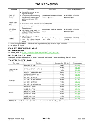
Revision: October 2006 EC-129 2006 Titan](https://image.slidesharecdn.com/ec-110402131317-phpapp02/85/Ec-129-320.jpg)


![TROUBLE DIAGNOSIS FOR INTERMITTENT INCIDENT
TROUBLE DIAGNOSIS FOR INTERMITTENT INCIDENT PFP:00006
Description UBS00NB1
Intermittent incidents may occur. In many cases, the malfunction resolves itself (the part or circuit function
returns to normal without intervention). It is important to realize that the symptoms described in the customer's
complaint often do not recur on (1st trip) DTC visits. Realize also that the most frequent cause of intermittent
incidents occurrences is poor electrical connections. Because of this, the conditions under which the incident
occurred may not be clear. Therefore, circuit checks made as part of the standard diagnostic procedure may
not indicate the specific malfunctioning area.
Common Intermittent Incidents Report Situations
STEP in Work Flow Situation
2 The CONSULT-II is used. The SELF-DIAG RESULTS screen shows time data other than [0] or [1t].
3 or 4 The symptom described by the customer does not recur.
5 (1st trip) DTC does not appear during the DTC Confirmation Procedure.
10 The Diagnostic Procedure for PXXXX does not indicate the malfunctioning area.
Diagnostic Procedure UBS00NB2
1. INSPECTION START
Erase (1st trip) DTCs. Refer to EC-61, "HOW TO ERASE EMISSION-RELATED DIAGNOSTIC INFORMA-
TION" .
>> GO TO 2.
2. CHECK GROUND TERMINALS
Check ground terminals for corroding or loose connection.
Refer to EC-156, "Ground Inspection" .
OK or NG
OK >> GO TO 3.
NG >> Repair or replace.
3. SEARCH FOR ELECTRICAL INCIDENT
Perform GI-27, "How to Perform Efficient Diagnosis for an Electrical Incident" , “INCIDENT SIMULATION
TESTS”.
OK or NG
OK >> GO TO 4.
NG >> Repair or replace.
4. CHECK CONNECTOR TERMINALS
Refer to GI-24, "How to Check Terminal" , “HOW TO PROBE CONNECTORS”, “How to Check Enlarged Con-
tact Spring of Terminal”.
OK or NG
OK >> INSPECTION END
NG >> Repair or replace connector.
Revision: October 2006 EC-150 2006 Titan](https://image.slidesharecdn.com/ec-110402131317-phpapp02/85/Ec-150-320.jpg)

![POWER SUPPLY AND GROUND CIRCUIT
Specification data are reference values and are measured between each terminal and ground.
CAUTION:
Do not use ECM ground terminals when measuring input/output voltage. Doing so may result in dam-
age to the ECM's transistor. Use a ground other than ECM terminals, such as the ground.
TER-
WIRE
MINAL ITEM CONDITION DATA (DC Voltage)
COLOR
NO.
[Engine is running]
1 B ECM ground Body ground
G Idle speed
[Ignition switch: OFF] 0V
109 L/W Ignition switch BATTERY VOLTAGE
[Ignition switch: ON]
(11 - 14V)
[Engine is running]
[Ignition switch: OFF]
0 - 1.5V
G For a few seconds after turning ignition
ECM relay switch OFF
111 W/B
(Self shut-off)
[Ignition switch: OFF]
BATTERY VOLTAGE
G More than a few seconds after turning igni- (11 - 14V)
tion switch OFF
115 B [Engine is running]
ECM ground Body ground
116 B/W G Idle speed
119 BR BATTERY VOLTAGE
Power supply for ECM [Ignition switch: ON]
120 BR (11 - 14V)
Diagnostic Procedure UBS00NB4
1. INSPECTION START
Start engine.
Is engine running?
Yes or No
Yes >> GO TO 8.
No >> GO TO 2.
2. CHECK ECM POWER SUPPLY CIRCUIT-I
1. Turn ignition switch OFF and then ON.
2. Check voltage between ECM terminal 109 and ground with
CONSULT-II or tester.
Voltage: Battery voltage
OK or NG
OK >> GO TO 4.
NG >> GO TO 3.
MBIB0015E
3. DETECT MALFUNCTIONING PART
Check the following.
G 10A fuse
G Harness for open or short between ECM and fuse
>> Repair harness or connectors.
Revision: October 2006 EC-152 2006 Titan](https://image.slidesharecdn.com/ec-110402131317-phpapp02/85/Ec-152-320.jpg)


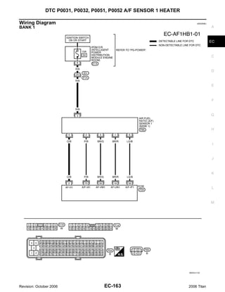
![DTC P0031, P0032, P0051, P0052 A/F SENSOR 1 HEATER
Specification data are reference values and are measured between each terminal and ground.
Pulse signal is measured by CONSULT-II.
CAUTION:
Do not use ECM ground terminals when measuring input/output voltage. Doing so may result in dam-
age to the ECM's transistor. Use a ground other than ECM terminals, such as the ground.
TER-
WIRE
MINAL ITEM CONDITION DATA (DC Voltage)
COLOR
NO.
Approximately 5V
[Engine is running]
A/F sensor 1 heater
2 O/B G Warm-up condition
(bank 1)
G Idle speed
PBIB1584E
16 BR/R Approximately 3.1V
[Engine is running]
35 BR/G Approximately 2.6V
A/F sensor 1 (bank 1) G Warm-up condition
56 LG/B Approximately 2.3V
G Idle speed
75 P/B Approximately 2.3V
: Average voltage for pulse signal (Actual pulse signal can be confirmed by oscilloscope.)
Revision: October 2006 EC-164 2006 Titan](https://image.slidesharecdn.com/ec-110402131317-phpapp02/85/Ec-164-320.jpg)

![DTC P0031, P0032, P0051, P0052 A/F SENSOR 1 HEATER
Specification data are reference values and are measured between each terminal and ground.
Pulse signal is measured by CONSULT-II.
CAUTION:
Do not use ECM ground terminals when measuring input/output voltage. Doing so may result in dam-
age to the ECM's transistor. Use a ground other than ECM terminals, such as the ground.
TER-
WIRE
MINAL ITEM CONDITION DATA (DC Voltage)
COLOR
NO.
Approximately 5V
[Engine is running]
A/F sensor 1 heater
24 BR/W G Warm-up condition
(bank 2)
G Idle speed
PBIB1584E
57 L/P Approximately 2.6V
[Engine is running]
58 GR/G Approximately 2.3V
A/F sensor 1 (bank 2) G Warm-up condition
76 G/L Approximately 3.1V
G Idle speed
77 BR/B Approximately 2.3V
: Average voltage for pulse signal (Actual pulse signal can be confirmed by oscilloscope.)
Diagnostic Procedure UBS00NBK
1. CHECK GROUND CONNECTIONS
1. Turn ignition switch OFF.
2. Loosen and retighten three ground screws on the body.
Refer to EC-156, "Ground Inspection" .
BBIA0354E
OK or NG
OK >> GO TO 2.
NG >> Repair or replace ground connections.
Revision: October 2006 EC-166 2006 Titan](https://image.slidesharecdn.com/ec-110402131317-phpapp02/85/Ec-166-320.jpg)


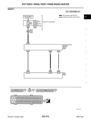
![DTC P0037, P0038, P0057, P0058 HO2S2 HEATER
Specification data are reference values and are measured between each terminal and ground.
CAUTION:
Do not use ECM ground terminals when measuring input/output voltage. Doing so may result in dam-
age to the ECM's transistor. Use a ground other than ECM terminals, such as the ground.
TER-
WIRE
MINAL ITEM CONDITION DATA (DC Voltage)
COLOR
NO.
[Engine is running]
G Engine speed: Below 3,600 rpm after the
following conditions are met.
– Engine: After warming up 0 - 1.0V
– Keeping the engine speed between 3,500
Heated oxygen sensor 2 and 4,000 rpm for 1 minute and at idle for 1
6 GR
heater (bank 1) minute under no load
[Ignition switch: ON]
G Engine: Stopped BATTERY VOLTAGE
[Engine is running] (11 - 14V)
G Engine speed: Above 3,600 rpm.
[Engine is running]
G Revving engine from idle to 3,000 rpm
quickly after the following conditions are
Heated oxygen sensor 2 met.
55 R 0 - Approximately 1.0V
(bank 1) – Engine: After warming up
– Keeping the engine speed between 3,500
and 4,000 rpm for 1 minute and at idle for 1
minute under no load
[Engine is running]
Sensor ground
78 B/W G Warm-up condition Approximately 0V
(Heated oxygen sensor 2)
G Idle speed
Revision: October 2006 EC-172 2006 Titan](https://image.slidesharecdn.com/ec-110402131317-phpapp02/85/Ec-172-320.jpg)
![DTC P0037, P0038, P0057, P0058 HO2S2 HEATER
Specification data are reference values and are measured between each terminal and ground.
CAUTION:
Do not use ECM ground terminals when measuring input/output voltage. Doing so may result in dam-
age to the ECM's transistor. Use a ground other than ECM terminals, such as the ground.
TER-
WIRE
MINAL ITEM CONDITION DATA (DC Voltage)
COLOR
NO.
[Engine is running]
G Engine speed: Below 3,600 rpm after the
following conditions are met.
– Engine: After warming up 0 - 1.0V
– Keeping the engine speed between 3,500
Heated oxygen sensor 2 and 4,000 rpm for 1 minute and at idle for 1
25 O/G
heater (bank 2) minute under no load
[Ignition switch: ON]
G Engine: Stopped BATTERY VOLTAGE
[Engine is running] (11 - 14V)
G Engine speed: Above 3,600 rpm.
[Engine is running]
G Revving engine from idle to 3,000 rpm
quickly after the following conditions are
Heated oxygen sensor 2 met.
74 L 0 - Approximately 1.0V
(bank 2) – Engine: After warming up
– Keeping the engine speed between 3,500
and 4,000 rpm for 1 minute and at idle for 1
minute under no load
[Engine is running]
Sensor ground
78 B/W G Warm-up condition Approximately 0V
(Heated oxygen sensor 2)
G Idle speed
Diagnostic Procedure UBS00NBS
1. CHECK GROUND CONNECTIONS
1. Turn ignition switch OFF.
2. Loosen and retighten three ground screws on the body.
Refer to EC-156, "Ground Inspection" .
BBIA0354E
OK or NG
OK >> GO TO 2.
NG >> Repair or replace ground connections.
Revision: October 2006 EC-174 2006 Titan](https://image.slidesharecdn.com/ec-110402131317-phpapp02/85/Ec-174-320.jpg)


![DTC P0101 MAF SENSOR
Specification data are reference values and are measured between each terminal and ground.
CAUTION: A
Do not use ECM ground terminals when measuring input/output voltage. Doing so may result in dam-
age to the ECM's transistor. Use a ground other than ECM terminals, such as the ground.
TER- EC
WIRE
MINAL ITEM CONDITION DATA (DC Voltage)
COLOR
NO.
[Engine is running] C
G Warm-up condition 1.0 - 1.3V
G Idle speed
51 W Mass air flow sensor
[Engine is running] D
G Warm-up condition 1.7 - 2.1V
G Engine speed: 2,500 rpm.
[Engine is running] E
67 B Sensor ground G Warm-up condition Approximately 0V
G Idle speed
F
[Engine is running]
[Ignition switch: OFF]
0 - 1.5V
G For a few seconds after turning ignition
ECM relay switch OFF G
111 W/B
(Self shut-off)
[Ignition switch: OFF]
BATTERY VOLTAGE
G More than a few seconds after turning igni- (11 - 14V)
tion switch OFF H
119 BR BATTERY VOLTAGE
Power supply for ECM [Ignition switch: ON]
120 BR (11 - 14V)
I
Diagnostic Procedure UBS00NC1
1. INSPECTION START
J
Which malfunction (A or B) is duplicated?
A or B
A >> GO TO 3. K
B >> GO TO 2.
2. CHECK INTAKE SYSTEM
L
Check the following for connection.
G Air duct
G Vacuum hoses M
G Intake air passage between air duct to intake manifold
OK or NG
OK >> GO TO 3.
NG >> Reconnect the parts.
Revision: October 2006 EC-181 2006 Titan](https://image.slidesharecdn.com/ec-110402131317-phpapp02/85/Ec-181-320.jpg)


![DTC P0102, P0103 MAF SENSOR
Specification data are reference values and are measured between each terminal and ground.
CAUTION: A
Do not use ECM ground terminals when measuring input/output voltage. Doing so may result in dam-
age to the ECM's transistor. Use a ground other than ECM terminals, such as the ground.
TER- EC
WIRE
MINAL ITEM CONDITION DATA (DC Voltage)
COLOR
NO.
[Engine is running] C
G Warm-up condition 1.0 - 1.3V
G Idle speed
51 W Mass air flow sensor
[Engine is running] D
G Warm-up condition 1.7 - 2.1V
G Engine speed: 2,500 rpm.
[Engine is running] E
67 B Sensor ground G Warm-up condition Approximately 0V
G Idle speed
F
[Engine is running]
[Ignition switch: OFF]
0 - 1.5V
G For a few seconds after turning ignition
ECM relay switch OFF G
111 W/B
(Self shut-off)
[Ignition switch: OFF]
BATTERY VOLTAGE
G More than a few seconds after turning igni- (11 - 14V)
tion switch OFF H
119 BR BATTERY VOLTAGE
Power supply for ECM [Ignition switch: ON]
120 BR (11 - 14V)
I
Diagnostic Procedure UBS00NC9
1. INSPECTION START
J
Which malfunction (P0102 or P0103) is duplicated?
P0102 or P0103
P0102 >> GO TO 2. K
P0103 >> GO TO 3.
2. CHECK INTAKE SYSTEM
L
Check the following for connection.
G Air duct
G Vacuum hoses M
G Intake air passage between air duct to intake manifold
OK or NG
OK >> GO TO 3.
NG >> Reconnect the parts.
Revision: October 2006 EC-189 2006 Titan](https://image.slidesharecdn.com/ec-110402131317-phpapp02/85/Ec-189-320.jpg)


![DTC P0122, P0123 TP SENSOR
Specification data are reference values and are measured between each terminal and ground.
CAUTION: A
Do not use ECM ground terminals when measuring input/output voltage. Doing so may result in dam-
age to the ECM's transistor. Use a ground other than ECM terminals, such as the ground.
TER- EC
WIRE
MINAL ITEM CONDITION DATA (DC Voltage)
COLOR
NO.
Sensor power supply C
47 Y [Ignition switch: ON] Approximately 5V
(Throttle position sensor)
[Ignition switch: ON]
G Engine: Stopped D
More than 0.36V
G Selector lever: D
G Accelerator pedal: Fully released
50 B Throttle position sensor 1
[Ignition switch: ON] E
G Engine: Stopped
Less than 4.75V
G Selector lever: D
G Accelerator pedal: Fully depressed F
[Engine is running]
Sensor ground
66 R G Warm-up condition Approximately 0V
(Throttle position sensor)
G Idle speed G
[Ignition switch: ON]
G Engine: Stopped
Less than 4.75V H
G Selector lever: D
G Accelerator pedal: Fully released
69 W Throttle position sensor 2
[Ignition switch: ON] I
G Engine: Stopped
More than 0.36V
G Selector lever: D
G Accelerator pedal: Fully depressed J
Sensor power supply
91 W/R [Ignition switch: ON] Approximately 5V
(APP sensor 2)
Diagnostic Procedure UBS00NCH
K
1. CHECK GROUND CONNECTIONS
1. Turn ignition switch OFF. L
2. Loosen and retighten three ground screws on the body.
Refer to EC-156, "Ground Inspection" .
M
BBIA0354E
OK or NG
OK >> GO TO 2.
NG >> Repair or replace ground connections.
Revision: October 2006 EC-207 2006 Titan](https://image.slidesharecdn.com/ec-110402131317-phpapp02/85/Ec-207-320.jpg)


![DTC P0125 ECT SENSOR
3. CHECK THERMOSTAT OPERATION A
When the engine is cold [lower than 70°C (158°F)] condition, grasp lower radiator hose and confirm the engine
coolant does not flow.
OK or NG EC
OK >> GO TO 4.
NG >> Repair or replace thermostat. Refer to CO-21, "THERMOSTAT AND WATER PIPING" .
C
4. CHECK INTERMITTENT INCIDENT
Refer to EC-150, "TROUBLE DIAGNOSIS FOR INTERMITTENT INCIDENT" .
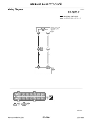
For Wiring Diagram, refer to EC-200, "Wiring Diagram" . D
>> INSPECTION END
E
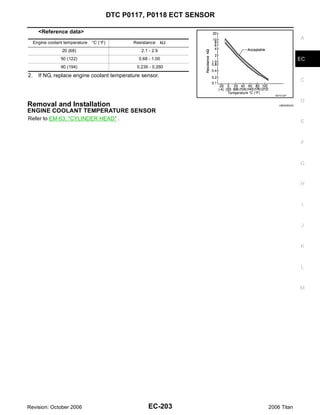
Component Inspection UBS00NCO
ENGINE COOLANT TEMPERATURE SENSOR
1. Check resistance between engine coolant temperature sensor F
terminals 1 and 2 as shown in the figure.
G
H
PBIB2005E I
<Reference data>
J
Engine coolant temperature °C (°F) Resistance kΩ
20 (68) 2.1 - 2.9
50 (122) 0.68 - 1.00 K
90 (194) 0.236 - 0.260
2. If NG, replace engine coolant temperature sensor.
L
SEF012P
M
Removal and Installation UBS00NCP
ENGINE COOLANT TEMPERATURE SENSOR
Refer to CO-21, "THERMOSTAT AND WATER PIPING" .
Revision: October 2006 EC-213 2006 Titan](https://image.slidesharecdn.com/ec-110402131317-phpapp02/85/Ec-213-320.jpg)


![DTC P0130, P0150 A/F SENSOR 1
Specification data are reference values and are measured between each terminal and ground.
Pulse signal is measured by CONSULT-II. A
CAUTION:
Do not use ECM ground terminals when measuring input/output voltage. Doing so may result in dam-
age to the ECM's transistor. Use a ground other than ECM terminals, such as the ground. EC
TER-
WIRE
MINAL ITEM CONDITION DATA (DC Voltage)
COLOR
NO.
C
Approximately 5V
[Engine is running] D
A/F sensor 1 heater
2 O/B G Warm-up condition
(bank 1)
G Idle speed
E
PBIB1584E
16 BR/R Approximately 3.1V
[Engine is running] F
35 BR/G Approximately 2.6V
A/F sensor 1 (bank 1) G Warm-up condition
56 LG/B Approximately 2.3V
G Idle speed
75 P/B Approximately 2.3V
G
: Average voltage for pulse signal (Actual pulse signal can be confirmed by oscilloscope.)
H
I
J
K
L
M
Revision: October 2006 EC-223 2006 Titan](https://image.slidesharecdn.com/ec-110402131317-phpapp02/85/Ec-223-320.jpg)

![DTC P0130, P0150 A/F SENSOR 1
Specification data are reference values and are measured between each terminal and ground.
Pulse signal is measured by CONSULT-II. A
CAUTION:
Do not use ECM ground terminals when measuring input/output voltage. Doing so may result in dam-
age to the ECM's transistor. Use a ground other than ECM terminals, such as the ground. EC
TER-
WIRE
MINAL ITEM CONDITION DATA (DC Voltage)
COLOR
NO.
C
Approximately 5V
[Engine is running] D
A/F sensor 1 heater
24 BR/W G Warm-up condition
(bank 2)
G Idle speed
E
PBIB1584E
57 L/P Approximately 2.6V
[Engine is running] F
58 GR/G Approximately 2.3V
A/F sensor 1 (bank 2) G Warm-up condition
76 G/L Approximately 3.1V
G Idle speed
77 BR/B Approximately 2.3V
G
: Average voltage for pulse signal (Actual pulse signal can be confirmed by oscilloscope.)
Diagnostic Procedure UBS00ND7
H
1. CHECK GROUND CONNECTIONS
1. Turn ignition switch OFF.
I
2. Loosen and retighten three ground screws on the body.
Refer to EC-156, "Ground Inspection" .
J
K
L
BBIA0354E
M
OK or NG
OK >> GO TO 2.
NG >> Repair or replace ground connections.
Revision: October 2006 EC-225 2006 Titan](https://image.slidesharecdn.com/ec-110402131317-phpapp02/85/Ec-225-320.jpg)


![DTC P0131, P0151 A/F SENSOR 1
Specification data are reference values and are measured between each terminal and ground.
Pulse signal is measured by CONSULT-II.
CAUTION:
Do not use ECM ground terminals when measuring input/output voltage. Doing so may result in dam-
age to the ECM's transistor. Use a ground other than ECM terminals, such as the ground.
TER-
WIRE
MINAL ITEM CONDITION DATA (DC Voltage)
COLOR
NO.
Approximately 5V
[Engine is running]
A/F sensor 1 heater
2 O/B G Warm-up condition
(bank 1)
G Idle speed
PBIB1584E
16 BR/R Approximately 3.1V
[Engine is running]
35 BR/G Approximately 2.6V
A/F sensor 1 (bank 1) G Warm-up condition
56 LG/B Approximately 2.3V
G Idle speed
75 P/B Approximately 2.3V
: Average voltage for pulse signal (Actual pulse signal can be confirmed by oscilloscope.)
Revision: October 2006 EC-232 2006 Titan](https://image.slidesharecdn.com/ec-110402131317-phpapp02/85/Ec-232-320.jpg)

![DTC P0131, P0151 A/F SENSOR 1
Specification data are reference values and are measured between each terminal and ground.
Pulse signal is measured by CONSULT-II.
CAUTION:
Do not use ECM ground terminals when measuring input/output voltage. Doing so may result in dam-
age to the ECM's transistor. Use a ground other than ECM terminals, such as the ground.
TER-
WIRE
MINAL ITEM CONDITION DATA (DC Voltage)
COLOR
NO.
Approximately 5V
[Engine is running]
A/F sensor 1 heater
24 BR/W G Warm-up condition
(bank 2)
G Idle speed
PBIB1584E
57 L/P Approximately 2.6V
[Engine is running]
58 GR/G Approximately 2.3V
A/F sensor 1 (bank 2) G Warm-up condition
76 G/L Approximately 3.1V
G Idle speed
77 BR/B Approximately 2.3V
: Average voltage for pulse signal (Actual pulse signal can be confirmed by oscilloscope.)
Diagnostic Procedure UBS00NDE
1. CHECK GROUND CONNECTIONS
1. Turn ignition switch OFF.
2. Loosen and retighten three ground screws on the body.
Refer to EC-156, "Ground Inspection" .
BBIA0354E
OK or NG
OK >> GO TO 2.
NG >> Repair or replace ground connections.
Revision: October 2006 EC-234 2006 Titan](https://image.slidesharecdn.com/ec-110402131317-phpapp02/85/Ec-234-320.jpg)


![DTC P0132, P0152 A/F SENSOR 1
Specification data are reference values and are measured between each terminal and ground.
Pulse signal is measured by CONSULT-II. A
CAUTION:
Do not use ECM ground terminals when measuring input/output voltage. Doing so may result in dam-
age to the ECM's transistor. Use a ground other than ECM terminals, such as the ground. EC
TER-
WIRE
MINAL ITEM CONDITION DATA (DC Voltage)
COLOR
NO.
C
Approximately 5V
[Engine is running] D
A/F sensor 1 heater
2 O/B G Warm-up condition
(bank 1)
G Idle speed
E
PBIB1584E
16 BR/R Approximately 3.1V
[Engine is running] F
35 BR/G Approximately 2.6V
A/F sensor 1 (bank 1) G Warm-up condition
56 LG/B Approximately 2.3V
G Idle speed
75 P/B Approximately 2.3V
G
: Average voltage for pulse signal (Actual pulse signal can be confirmed by oscilloscope.)
H
I
J
K
L
M
Revision: October 2006 EC-241 2006 Titan](https://image.slidesharecdn.com/ec-110402131317-phpapp02/85/Ec-241-320.jpg)

![DTC P0132, P0152 A/F SENSOR 1
Specification data are reference values and are measured between each terminal and ground.
Pulse signal is measured by CONSULT-II. A
CAUTION:
Do not use ECM ground terminals when measuring input/output voltage. Doing so may result in dam-
age to the ECM's transistor. Use a ground other than ECM terminals, such as the ground. EC
TER-
WIRE
MINAL ITEM CONDITION DATA (DC Voltage)
COLOR
NO.
C
Approximately 5V
[Engine is running] D
A/F sensor 1 heater
24 BR/W G Warm-up condition
(bank 2)
G Idle speed
E
PBIB1584E
57 L/P Approximately 2.6V
[Engine is running] F
58 GR/G Approximately 2.3V
A/F sensor 1 (bank 2) G Warm-up condition
76 G/L Approximately 3.1V
G Idle speed
77 BR/B Approximately 2.3V
G
: Average voltage for pulse signal (Actual pulse signal can be confirmed by oscilloscope.)
Diagnostic Procedure UBS00NDL
H
1. CHECK GROUND CONNECTIONS
1. Turn ignition switch OFF.
I
2. Loosen and retighten three ground screws on the body.
Refer to EC-156, "Ground Inspection" .
J
K
L
BBIA0354E
M
OK or NG
OK >> GO TO 2.
NG >> Repair or replace ground connections.
Revision: October 2006 EC-243 2006 Titan](https://image.slidesharecdn.com/ec-110402131317-phpapp02/85/Ec-243-320.jpg)


![DTC P0133, P0153 A/F SENSOR 1
Specification data are reference values and are measured between each terminal and ground.
Pulse signal is measured by CONSULT-II. A
CAUTION:
Do not use ECM ground terminals when measuring input/output voltage. Doing so may result in dam-
age to the ECM's transistor. Use a ground other than ECM terminals, such as the ground. EC
TER-
WIRE
MINAL ITEM CONDITION DATA (DC Voltage)
COLOR
NO.
C
Approximately 5V
[Engine is running] D
A/F sensor 1 heater
2 O/B G Warm-up condition
(bank 1)
G Idle speed
E
PBIB1584E
16 BR/R Approximately 3.1V
[Engine is running] F
35 BR/G Approximately 2.6V
A/F sensor 1 (bank 1) G Warm-up condition
56 LG/B Approximately 2.3V
G Idle speed
75 P/B Approximately 2.3V
G
: Average voltage for pulse signal (Actual pulse signal can be confirmed by oscilloscope.)
H
I
J
K
L
M
Revision: October 2006 EC-251 2006 Titan](https://image.slidesharecdn.com/ec-110402131317-phpapp02/85/Ec-251-320.jpg)

![DTC P0133, P0153 A/F SENSOR 1
Specification data are reference values and are measured between each terminal and ground.
Pulse signal is measured by CONSULT-II. A
CAUTION:
Do not use ECM ground terminals when measuring input/output voltage. Doing so may result in dam-
age to the ECM's transistor. Use a ground other than ECM terminals, such as the ground. EC
TER-
WIRE
MINAL ITEM CONDITION DATA (DC Voltage)
COLOR
NO.
C
Approximately 5V
[Engine is running] D
A/F sensor 1 heater
24 BR/W G Warm-up condition
(bank 2)
G Idle speed
E
PBIB1584E
57 L/P Approximately 2.6V
[Engine is running] F
58 GR/G Approximately 2.3V
A/F sensor 1 (bank 2) G Warm-up condition
76 G/L Approximately 3.1V
G Idle speed
77 BR/B Approximately 2.3V
G
: Average voltage for pulse signal (Actual pulse signal can be confirmed by oscilloscope.)
Diagnostic Procedure UBS00NDS
H
1. CHECK GROUND CONNECTIONS
1. Turn ignition switch OFF.
I
2. Loosen and retighten three ground screws on the body.
Refer to EC-156, "Ground Inspection" .
J
K
L
BBIA0354E
M
OK or NG
OK >> GO TO 2.
NG >> Repair or replace ground connections.
Revision: October 2006 EC-253 2006 Titan](https://image.slidesharecdn.com/ec-110402131317-phpapp02/85/Ec-253-320.jpg)


![DTC P0137, P0157 HO2S2
DTC Confirmation Procedure UBS00NDX
NOTE:
If DTC confirmation Procedure has been previously conducted, always turn ignition switch OFF and wait at
least 10 seconds before conducting the next test.
WITH CONSULT-II
TESTING CONDITION:
For better results, perform “DTC WORK SUPPORT” at a temperature of 0 to 30 °C (32 to 86 °F).
1. Turn ignition switch ON and select “DATA MONITOR” mode with
CONSULT-II.
2. Start engine and warm it up to the normal operating tempera-
ture.
3. Turn ignition switch OFF and wait at least 10 seconds.
4. Start engine and keep the engine speed between 3,500 and
4,000 rpm for at least 1 minute under no load.
5. Let engine idle for 1 minute.
6. Make sure that “COOLAN TEMP/S” indicates more than 70°C
(158°F). SEF174Y
If not, warm up engine and go to next step when “COOLAN
TEMP/S” indication reaches to 70°C (158°F).
7. Open engine hood.
8. Select “HO2S2 (B1) P1147” (for DTC P0137) or “HO2S2 (B2) P1167” (for DTC P0157) of “HO2S2” in
“DTC WORK SUPPORT” mode with CONSULT-II.
9. Start engine and following the instruction of CONSULT-II.
PBIB2373E
NOTE:
It will take at most 10 minutes until “COMPLETED” is displayed.
10. Make sure that “OK” is displayed after touching “SELF-DIAG RESULTS”.
If “NG” is displayed, refer to EC-265, "Diagnostic Procedure" .
If “CAN NOT BE DIAGNOSED” is displayed, perform the following.
a. Turn ignition switch OFF and leave the vehicle in a cool place (soak the vehicle).
b. Return to step 1.
Overall Function Check UBS00NDY
Use this procedure to check the overall function of the heated oxygen sensor 2 circuit. During this check, a 1st
trip DTC might not be confirmed.
WITH GST
1. Start engine and warm it up to the normal operating temperature.
2. Turn ignition switch OFF and wait at least 10 seconds.
3. Start engine and keep the engine speed between 3,500 and 4,000 rpm for at least 1 minute under no load.
4. Let engine idle for 1 minute.
5. Set voltmeter probes between ECM terminal 55 [HO2S2 (B1) signal] or 74 [HO2S2 (B2) signal] and
ground.
Revision: October 2006 EC-260 2006 Titan](https://image.slidesharecdn.com/ec-110402131317-phpapp02/85/Ec-260-320.jpg)

![DTC P0137, P0157 HO2S2
Specification data are reference values and are measured between each terminal and ground.
CAUTION: A
Do not use ECM ground terminals when measuring input/output voltage. Doing so may result in dam-
age to the ECM's transistor. Use a ground other than ECM terminals, such as the ground.
TER- EC
WIRE
MINAL ITEM CONDITION DATA (DC Voltage)
COLOR
NO.
[Engine is running] C
G Engine speed: Below 3,600 rpm after the
following conditions are met.
– Engine: After warming up 0 - 1.0V
D
– Keeping the engine speed between 3,500
Heated oxygen sensor 2 and 4,000 rpm for 1 minute and at idle for 1
6 GR
heater (bank 1) minute under no load
E
[Ignition switch: ON]
G Engine: Stopped BATTERY VOLTAGE
[Engine is running] (11 - 14V)
F
G Engine speed: Above 3,600 rpm.
[Engine is running]
G Revving engine from idle to 3,000 rpm
G
quickly after the following conditions are
Heated oxygen sensor 2 met.
55 R 0 - Approximately 1.0V
(bank 1) – Engine: After warming up
– Keeping the engine speed between 3,500
H
and 4,000 rpm for 1 minute and at idle for 1
minute under no load
[Engine is running] I
Sensor ground
78 B/W G Warm-up condition Approximately 0V
(Heated oxygen sensor 2)
G Idle speed
J
K
L
M
Revision: October 2006 EC-263 2006 Titan](https://image.slidesharecdn.com/ec-110402131317-phpapp02/85/Ec-263-320.jpg)
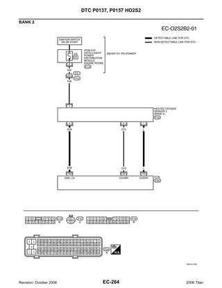
![DTC P0137, P0157 HO2S2
Specification data are reference values and are measured between each terminal and ground.
CAUTION: A
Do not use ECM ground terminals when measuring input/output voltage. Doing so may result in dam-
age to the ECM's transistor. Use a ground other than ECM terminals, such as the ground.
TER- EC
WIRE
MINAL ITEM CONDITION DATA (DC Voltage)
COLOR
NO.
[Engine is running] C
G Engine speed: Below 3,600 rpm after the
following conditions are met.
– Engine: After warming up 0 - 1.0V
D
– Keeping the engine speed between 3,500
Heated oxygen sensor 2 and 4,000 rpm for 1 minute and at idle for 1
25 O/G
heater (bank 2) minute under no load
E
[Ignition switch: ON]
G Engine: Stopped BATTERY VOLTAGE
[Engine is running] (11 - 14V)
F
G Engine speed: Above 3,600 rpm.
[Engine is running]
G Revving engine from idle to 3,000 rpm
G
quickly after the following conditions are
Heated oxygen sensor 2 met.
74 L 0 - Approximately 1.0V
(bank 2) – Engine: After warming up
– Keeping the engine speed between 3,500
H
and 4,000 rpm for 1 minute and at idle for 1
minute under no load
[Engine is running] I
Sensor ground
78 B/W G Warm-up condition Approximately 0V
(Heated oxygen sensor 2)
G Idle speed
J
Diagnostic Procedure UBS00NE0
1. CHECK GROUND CONNECTIONS
K
1. Turn ignition switch OFF.
2. Loosen and retighten three ground screws on the body.
Refer to EC-156, "Ground Inspection" .
L
M
BBIA0354E
OK or NG
OK >> GO TO 2.
NG >> Repair or replace ground connections.
Revision: October 2006 EC-265 2006 Titan](https://image.slidesharecdn.com/ec-110402131317-phpapp02/85/Ec-265-320.jpg)
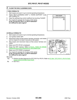


![DTC P0137, P0157 HO2S2
G Before installing new oxygen sensor, clean exhaust system threads using Oxygen Sensor Thread
Cleaner tool J-43897-18 or J-43897-12 and approved anti-seize lubricant. A
Without CONSULT-II
1. Start engine and warm it up to the normal operating temperature.
EC
2. Turn ignition switch OFF and wait at least 10 seconds.
3. Start engine and keep the engine speed between 3,500 and 4,000 rpm for at least 1 minute under no load.
4. Let engine idle for 1 minute.
C
5. Set voltmeter probes between ECM terminal 55 [HO2S2 (B1) signal] or 74 [HO2S2 (B2) signal] and
ground.
6. Check the voltage when revving up to 4,000 rpm under no load D
at least 10 times.
(Depress and release accelerator pedal as soon as possible.)
The voltage should be above 0.58V at least once during this
procedure. E
If the voltage is above 0.58V at step 6, step 7 is not neces-
sary.
7. Keep vehicle at idling for 10 minutes, then check voltage. Or F
check the voltage when coasting from 80 km/h (50 MPH) in D
position.
The voltage should be below 0.18V at least once during this PBIB2054E
G
procedure.
8. If NG, replace heated oxygen sensor 2.
CAUTION: H
G Discard any heated oxygen sensor which has been dropped from a height of more than 0.5 m (19.7
in) onto a hard surface such as a concrete floor; use a new one.
G Before installing new oxygen sensor, clean exhaust system threads using Oxygen Sensor Thread
Cleaner tool J-43897-18 or J-43897-12 and approved anti-seize lubricant. I
Removal and Installation UBS00NE2
HEATED OXYGEN SENSOR 2 J
Refer to EM-21, "EXHAUST MANIFOLD AND THREE WAY CATALYST" .
K
L
M
Revision: October 2006 EC-269 2006 Titan](https://image.slidesharecdn.com/ec-110402131317-phpapp02/85/Ec-269-320.jpg)


![DTC P0138, P0158 HO2S2
9. Start engine and following the instruction of CONSULT-II.
PBIB2372E
NOTE:
It will take at most 10 minutes until “COMPLETED” is displayed.
10. Make sure that “OK” is displayed after touching “SELF-DIAG RESULTS”.
If “NG” is displayed, refer to EC-278, "PROCEDURE FOR MALFUNCTION B" .
If “CAN NOT BE DIAGNOSED” is displayed, perform the following.
a. Turn ignition switch OFF and leave the vehicle in a cool place (soak the vehicle).
b. Return to step 1.
Overall Function Check UBS00NE7
PROCEDURE FOR MALFUNCTION B
Use this procedure to check the overall function of the heated oxygen sensor 2 circuit. During this check, a 1st
trip DTC might not be confirmed.
With GST
1. Start engine and warm it up to the normal operating temperature.
2. Turn ignition switch OFF and wait at least 10 seconds.
3. Start engine and keep the engine speed between 3,500 and 4,000 rpm for at least 1 minute under no load.
4. Let engine idle for 1 minute.
5. Set voltmeter probes between ECM terminal 55 [HO2S2 (B2) signal] or 74 [HO2S2 (B1) signal] and
ground.
6. Check the voltage when revving up to 4,000 rpm under no load
at least 10 times.
(Depress and release accelerator pedal as soon as possible.)
The voltage should be below 0.18V at least once during this
procedure.
If the voltage can be confirmed in step 6, step 7 is not nec-
essary.
7. Keep vehicle at idling for 10 minutes, then check the voltage. Or
check the voltage when coasting from 80 km/h (50 MPH) in D
position.
The voltage should be below 0.18V at least once during this PBIB2054E
procedure.
8. If NG, go to EC-278, "PROCEDURE FOR MALFUNCTION B" .
Revision: October 2006 EC-272 2006 Titan](https://image.slidesharecdn.com/ec-110402131317-phpapp02/85/Ec-272-320.jpg)

![DTC P0138, P0158 HO2S2
Specification data are reference values and are measured between each terminal and ground.
CAUTION:
Do not use ECM ground terminals when measuring input/output voltage. Doing so may result in dam-
age to the ECM's transistor. Use a ground other than ECM terminals, such as the ground.
TER-
WIRE
MINAL ITEM CONDITION DATA (DC Voltage)
COLOR
NO.
[Engine is running]
G Engine speed: Below 3,600 rpm after the
following conditions are met.
– Engine: After warming up 0 - 1.0V
– Keeping the engine speed between 3,500
Heated oxygen sensor 2 and 4,000 rpm for 1 minute and at idle for 1
6 GR
heater (bank 1) minute under no load
[Ignition switch: ON]
G Engine: Stopped BATTERY VOLTAGE
[Engine is running] (11 - 14V)
G Engine speed: Above 3,600 rpm.
[Engine is running]
G Revving engine from idle to 3,000 rpm
quickly after the following conditions are
Heated oxygen sensor 2 met.
55 R 0 - Approximately 1.0V
(bank 1) – Engine: After warming up
– Keeping the engine speed between 3,500
and 4,000 rpm for 1 minute and at idle for 1
minute under no load
[Engine is running]
Sensor ground
78 B/W G Warm-up condition Approximately 0V
(Heated oxygen sensor 2)
G Idle speed
Revision: October 2006 EC-274 2006 Titan](https://image.slidesharecdn.com/ec-110402131317-phpapp02/85/Ec-274-320.jpg)

![DTC P0138, P0158 HO2S2
Specification data are reference values and are measured between each terminal and ground.
CAUTION:
Do not use ECM ground terminals when measuring input/output voltage. Doing so may result in dam-
age to the ECM's transistor. Use a ground other than ECM terminals, such as the ground.
TER-
WIRE
MINAL ITEM CONDITION DATA (DC Voltage)
COLOR
NO.
[Engine is running]
G Engine speed: Below 3,600 rpm after the
following conditions are met.
– Engine: After warming up 0 - 1.0V
– Keeping the engine speed between 3,500
Heated oxygen sensor 2 and 4,000 rpm for 1 minute and at idle for 1
25 O/G
heater (bank 2) minute under no load
[Ignition switch: ON]
G Engine: Stopped BATTERY VOLTAGE
[Engine is running] (11 - 14V)
G Engine speed: Above 3,600 rpm.
[Engine is running]
G Revving engine from idle to 3,000 rpm
quickly after the following conditions are
Heated oxygen sensor 2 met.
74 L 0 - Approximately 1.0V
(bank 2) – Engine: After warming up
– Keeping the engine speed between 3,500
and 4,000 rpm for 1 minute and at idle for 1
minute under no load
[Engine is running]
Sensor ground
78 B/W G Warm-up condition Approximately 0V
(Heated oxygen sensor 2)
G Idle speed
Diagnostic Procedure UBS00NE9
PROCEDURE FOR MALFUNCTION A
1. CHECK GROUND CONNECTIONS
1. Turn ignition switch OFF.
2. Loosen and retighten two ground screws on the body.
Refer to EC-156, "Ground Inspection" .
BBIA0354E
OK or NG
OK >> GO TO 2.
NG >> Repair or replace ground connections.
Revision: October 2006 EC-276 2006 Titan](https://image.slidesharecdn.com/ec-110402131317-phpapp02/85/Ec-276-320.jpg)


![DTC P0138, P0158 HO2S2
G Before installing new oxygen sensor, clean exhaust system threads using Oxygen Sensor Thread
Cleaner tool J-43897-18 or J-43897-12 and approved anti-seize lubricant.
Without CONSULT-II
1. Start engine and warm it up to the normal operating temperature.
2. Turn ignition switch OFF and wait at least 10 seconds.
3. Start engine and keep the engine speed between 3,500 and 4,000 rpm for at least 1 minute under no load.
4. Let engine idle for 1 minute.
5. Set voltmeter probes between ECM terminal 55 [HO2S2 (B1) signal] or 74 [HO2S2 (B2) signal] and
ground.
6. Check the voltage when revving up to 4,000 rpm under no load
at least 10 times.
(Depress and release accelerator pedal as soon as possible.)
The voltage should be above 0.58V at least once during this
procedure.
If the voltage is above 0.58V at step 6, step 7 is not neces-
sary.
7. Keep vehicle at idling for 10 minutes, then check voltage. Or
check the voltage when coasting from 80 km/h (50 MPH) in D
position.
The voltage should be below 0.18V at least once during this PBIB2054E
procedure.
8. If NG, replace heated oxygen sensor 2.
CAUTION:
G Discard any heated oxygen sensor which has been dropped from a height of more than 0.5 m (19.7
in) onto a hard surface such as a concrete floor; use a new one.
G Before installing new oxygen sensor, clean exhaust system threads (using Oxygen Sensor Thread
Cleaner tool J-43897-18 or J-43897-12) and approved anti-seize lubricant.
Removal and Installation UBS00NEB
HEATED OXYGEN SENSOR 2
Refer to EM-21, "EXHAUST MANIFOLD AND THREE WAY CATALYST" .
Revision: October 2006 EC-282 2006 Titan](https://image.slidesharecdn.com/ec-110402131317-phpapp02/85/Ec-282-320.jpg)
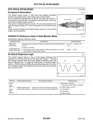
![DTC P0139, P0159 HO2S2
DTC Confirmation Procedure UBS00NEF
NOTE:
If DTC Confirmation Procedure has been previously conducted, always turn ignition switch OFF and wait at
least 10 seconds before conducting the next test.
WITH CONSULT-II
TESTING CONDITION:
For better results, perform “DTC WORK SUPPORT” at a temperature of 0 to 30 °C (32 to 86 °F).
1. Turn ignition switch ON and select “DATA MONITOR” mode with
CONSULT-II.
2. Start engine and warm it up to the normal operating tempera-
ture.
3. Turn ignition switch OFF and wait at least 10 seconds.
4. Start engine and keep the engine speed between 3,500 and
4,000 rpm for at least 1 minute under no load.
5. Let engine idle for 1 minute.
6. Make sure that “COOLAN TEMP/S” indicates more than 70°C
(158°F). SEF174Y
If not, warm up engine and go to next step when “COOLAN
TEMP/S” indication reaches to 70°C (158°F).
7. Open engine hood.
8. Select “HO2S2 (B1) P0139” or “HO2S2 (B2) P0159” of “HO2S2” in “DTC WORK SUPPORT” mode with
CONSULT-II.
9. Start engine and following the instruction of CONSULT-II.
PBIB2374E
NOTE:
It will take at most 10 minutes until “COMPLETED is displayed.
10. Make sure that “OK” is displayed after touching “SELF-DIAG RESULTS”.
If “NG” is displayed, refer to EC-289, "Diagnostic Procedure" .
If “CAN NOT BE DIAGNOSED” is displayed, perform the following.
a. Turn ignition switch OFF and leave the vehicle in a cool place (soak the vehicle).
b. Return to step 1.
Overall Function Check UBS00NEG
Use this procedure to check the overall function of the heated oxygen sensor 2 circuit. During this check, a 1st
trip DTC might not be confirmed.
WITH GST
1. Start engine and warm it up to the normal operating temperature.
2. Turn ignition switch OFF and wait at least 10 seconds.
3. Start engine and keep the engine speed between 3,500 and 4,000 rpm for at least 1 minute under no load.
4. Let engine idle for 1 minute.
5. Set voltmeter probes between ECM terminal 55 [HO2S2 (B1) signal] or 74 [HO2S2 (B2) signal] and
ground.
Revision: October 2006 EC-284 2006 Titan](https://image.slidesharecdn.com/ec-110402131317-phpapp02/85/Ec-284-320.jpg)
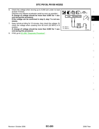

![DTC P0139, P0159 HO2S2
Specification data are reference values and are measured between each terminal and ground.
CAUTION: A
Do not use ECM ground terminals when measuring input/output voltage. Doing so may result in dam-
age to the ECM's transistor. Use a ground other than ECM terminals, such as the ground.
TER- EC
WIRE
MINAL ITEM CONDITION DATA (DC Voltage)
COLOR
NO.
[Engine is running] C
G Engine speed: Below 3,600 rpm after the
following conditions are met.
– Engine: After warming up 0 - 1.0V
D
– Keeping the engine speed between 3,500
Heated oxygen sensor 2 and 4,000 rpm for 1 minute and at idle for 1
6 GR
heater (bank 1) minute under no load
E
[Ignition switch: ON]
G Engine: Stopped BATTERY VOLTAGE
[Engine is running] (11 - 14V)
F
G Engine speed: Above 3,600 rpm.
[Engine is running]
G Revving engine from idle to 3,000 rpm
G
quickly after the following conditions are
Heated oxygen sensor 2 met.
55 R 0 - Approximately 1.0V
(bank 1) – Engine: After warming up
– Keeping the engine speed between 3,500
H
and 4,000 rpm for 1 minute and at idle for 1
minute under no load
[Engine is running] I
Sensor ground
78 B/W G Warm-up condition Approximately 0V
(Heated oxygen sensor 2)
G Idle speed
J
K
L
M
Revision: October 2006 EC-287 2006 Titan](https://image.slidesharecdn.com/ec-110402131317-phpapp02/85/Ec-287-320.jpg)

![DTC P0139, P0159 HO2S2
Specification data are reference values and are measured between each terminal and ground.
CAUTION: A
Do not use ECM ground terminals when measuring input/output voltage. Doing so may result in dam-
age to the ECM's transistor. Use a ground other than ECM terminals, such as the ground.
TER- EC
WIRE
MINAL ITEM CONDITION DATA (DC Voltage)
COLOR
NO.
[Engine is running] C
G Engine speed: Below 3,600 rpm after the
following conditions are met.
– Engine: After warming up 0 - 1.0V
D
– Keeping the engine speed between 3,500
Heated oxygen sensor 2 and 4,000 rpm for 1 minute and at idle for 1
25 O/G
heater (bank 2) minute under no load
E
[Ignition switch: ON]
G Engine: Stopped BATTERY VOLTAGE
[Engine is running] (11 - 14V)
F
G Engine speed: Above 3,600 rpm.
[Engine is running]
G Revving engine from idle to 3,000 rpm
G
quickly after the following conditions are
Heated oxygen sensor 2 met.
74 L 0 - Approximately 1.0V
(bank 2) – Engine: After warming up
– Keeping the engine speed between 3,500
H
and 4,000 rpm for 1 minute and at idle for 1
minute under no load
[Engine is running] I
Sensor ground
78 B/W G Warm-up condition Approximately 0V
(Heated oxygen sensor 2)
G Idle speed
J
Diagnostic Procedure UBS00NEI
1. CHECK GROUND CONNECTIONS
K
1. Turn ignition switch OFF.
2. Loosen and retighten three ground screws on the body.
Refer to EC-156, "Ground Inspection" .
L
M
BBIA0354E
OK or NG
OK >> GO TO 2.
NG >> Repair or replace ground connections.
Revision: October 2006 EC-289 2006 Titan](https://image.slidesharecdn.com/ec-110402131317-phpapp02/85/Ec-289-320.jpg)


![DTC P0139, P0159 HO2S2
G Before installing new oxygen sensor, clean exhaust system threads using Oxygen Sensor Thread
Cleaner tool J-43897-18 or J-43897-12 and approved anti-seize lubricant. A
Without CONSULT-II
1. Start engine and warm it up to the normal operating temperature.
EC
2. Turn ignition switch “OFF” and wait at least 10 seconds.
3. Start engine and keep the engine speed between 3,500 and 4,000 rpm for at least 1 minute under no load.
4. Let engine idle for 1 minute.
C
5. Set voltmeter probes between ECM terminal 55 [HO2S2 (B1) signal] or 74 [HO2S2 (B2) signal] and
ground.
6. Check the voltage when revving up to 4,000 rpm under no load D
at least 10 times.
(Depress and release accelerator pedal as soon as possible.)
The voltage should be above 0.58V at least once during this
procedure. E
If the voltage is above 0.58V at step 6, step 7 is not neces-
sary.
7. Keep vehicle at idling for 10 minutes, then check voltage. Or F
check the voltage when coasting from 80 km/h (50 MPH) in D
position.
The voltage should be below 0.18V at least once during this PBIB2054E
G
procedure.
8. If NG, replace heated oxygen sensor 2.
CAUTION: H
G Discard any heated oxygen sensor which has been dropped from a height of more than 0.5 m (19.7
in) onto a hard surface such as a concrete floor; use a new one.
G Before installing new oxygen sensor, clean exhaust system threads using Oxygen Sensor Thread
Cleaner tool J-43897-18 or J-43897-12 and approved anti-seize lubricant. I
Removal and Installation UBS00NEK
HEATED OXYGEN SENSOR 2 J
Refer to EM-21, "EXHAUST MANIFOLD AND THREE WAY CATALYST" .
K
L
M
Revision: October 2006 EC-293 2006 Titan](https://image.slidesharecdn.com/ec-110402131317-phpapp02/85/Ec-293-320.jpg)


![DTC P0171, P0174 FUEL INJECTION SYSTEM FUNCTION
Specification data are reference values and are measured between each terminal and ground.
Pulse signal is measured by CONSULT-II. A
CAUTION:
Do not use ECM ground terminals when measuring input/output voltage. Doing so may result in dam-
age to the ECM's transistor. Use a ground other than ECM terminals, such as the ground. EC
TER-
WIRE
MINAL ITEM CONDITION DATA (DC Voltage)
COLOR
NO.
C
Approximately 5V
[Engine is running] D
A/F sensor 1 heater
2 O/B G Warm-up condition
(bank 1)
G Idle speed
E
PBIB1584E
16 BR/R Approximately 3.1V
[Engine is running] F
35 BR/G Approximately 2.6V
A/F sensor 1 (bank 1) G Warm-up condition
56 LG/B Approximately 2.3V
G Idle speed
75 P/B Approximately 2.3V
G
BATTERY VOLTAGE
[Engine is running] (11 - 14V)
G Warm-up condition H
G Idle speed
NOTE:
The pulse cycle changes depending on rpm at I
O/L Fuel injector No. 5 idle.
21
BR Fuel injector No. 3
22 PBIB0042E
GR/W Fuel injector No. 1
23 BATTERY VOLTAGE J
O Fuel injector No. 7
44
(11 - 14V)
[Engine is running]
K
G Warm-up condition
G Engine speed: 2,000 rpm
L
PBIB0043E
: Average voltage for pulse signal (Actual pulse signal can be confirmed by oscilloscope.)
M
Revision: October 2006 EC-297 2006 Titan](https://image.slidesharecdn.com/ec-110402131317-phpapp02/85/Ec-297-320.jpg)

![DTC P0171, P0174 FUEL INJECTION SYSTEM FUNCTION
Specification data are reference values and are measured between each terminal and ground.
Pulse signal is measured by CONSULT-II. A
CAUTION:
Do not use ECM ground terminals when measuring input/output voltage. Doing so may result in dam-
age to the ECM's transistor. Use a ground other than ECM terminals, such as the ground. EC
TER-
WIRE
MINAL ITEM CONDITION DATA (DC Voltage)
COLOR
NO.
C
BATTERY VOLTAGE
[Engine is running] (11 - 14V)
G Warm-up condition D
G Idle speed
NOTE:
The pulse cycle changes depending on rpm at E
idle.
40 Y/G Fuel injector No. 6
41 P Fuel injector No. 4 PBIB0042E
42 L Fuel injector No. 2 BATTERY VOLTAGE F
63 G Fuel injector No. 8
(11 - 14V)
[Engine is running]
G Warm-up condition
G
G Engine speed: 2,000 rpm
H
PBIB0043E
Approximately 5V
I
[Engine is running]
A/F sensor 1 heater
24 BR/W G Warm-up condition
(bank 2)
G Idle speed J
PBIB1584E
K
57 L/P Approximately 2.6V
[Engine is running]
58 GR/G Approximately 2.3V
A/F sensor 1 (bank 2) G Warm-up condition
76 G/L Approximately 3.1V L
G Idle speed
77 BR/B Approximately 2.3V
: Average voltage for pulse signal (Actual pulse signal can be confirmed by oscilloscope.)
M
Revision: October 2006 EC-299 2006 Titan](https://image.slidesharecdn.com/ec-110402131317-phpapp02/85/Ec-299-320.jpg)

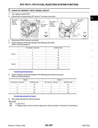
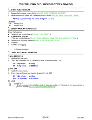
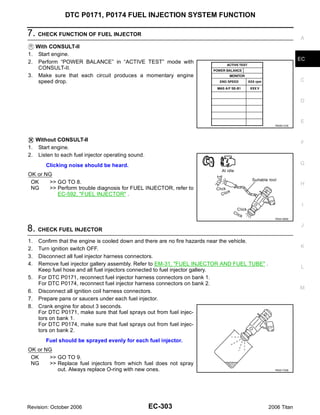


![DTC P0172, P0175 FUEL INJECTION SYSTEM FUNCTION
Specification data are reference values and are measured between each terminal and ground.
Pulse signal is measured by CONSULT-II.
CAUTION:
Do not use ECM ground terminals when measuring input/output voltage. Doing so may result in dam-
age to the ECM's transistor. Use a ground other than ECM terminals, such as the ground.
TER-
WIRE
MINAL ITEM CONDITION DATA (DC Voltage)
COLOR
NO.
Approximately 5V
[Engine is running]
A/F sensor 1 heater
2 O/B G Warm-up condition
(bank 1)
G Idle speed
PBIB1584E
16 BR/R Approximately 3.1V
[Engine is running]
35 BR/G Approximately 2.6V
A/F sensor 1 (bank 1) G Warm-up condition
56 LG/B Approximately 2.3V
G Idle speed
75 P/B Approximately 2.3V
BATTERY VOLTAGE
[Engine is running] (11 - 14V)
G Warm-up condition
G Idle speed
NOTE:
The pulse cycle changes depending on rpm at
O/L Fuel injector No. 5 idle.
21
BR Fuel injector No. 3
22 PBIB0042E
GR/W Fuel injector No. 1
23 BATTERY VOLTAGE
O Fuel injector No. 7
44
(11 - 14V)
[Engine is running]
G Warm-up condition
G Engine speed: 2,000 rpm
PBIB0043E
: Average voltage for pulse signal (Actual pulse signal can be confirmed by oscilloscope.)
Revision: October 2006 EC-308 2006 Titan](https://image.slidesharecdn.com/ec-110402131317-phpapp02/85/Ec-308-320.jpg)

![DTC P0172, P0175 FUEL INJECTION SYSTEM FUNCTION
Specification data are reference values and are measured between each terminal and ground.
Pulse signal is measured by CONSULT-II.
CAUTION:
Do not use ECM ground terminals when measuring input/output voltage. Doing so may result in dam-
age to the ECM's transistor. Use a ground other than ECM terminals, such as the ground.
TER-
WIRE
MINAL ITEM CONDITION DATA (DC Voltage)
COLOR
NO.
BATTERY VOLTAGE
[Engine is running] (11 - 14V)
G Warm-up condition
G Idle speed
NOTE:
The pulse cycle changes depending on rpm at
idle.
40 Y/G Fuel injector No. 6
41 P Fuel injector No. 4 PBIB0042E
42 L Fuel injector No. 2 BATTERY VOLTAGE
63 G Fuel injector No. 8
(11 - 14V)
[Engine is running]
G Warm-up condition
G Engine speed: 2,000 rpm
PBIB0043E
Approximately 5V
[Engine is running]
A/F sensor 1 heater
24 BR/W G Warm-up condition
(bank 2)
G Idle speed
PBIB1584E
57 L/P Approximately 2.6V
[Engine is running]
58 GR/G Approximately 2.3V
A/F sensor 1 (bank 2) G Warm-up condition
76 G/L Approximately 3.1V
G Idle speed
77 BR/B Approximately 2.3V
: Average voltage for pulse signal (Actual pulse signal can be confirmed by oscilloscope.)
Revision: October 2006 EC-310 2006 Titan](https://image.slidesharecdn.com/ec-110402131317-phpapp02/85/Ec-310-320.jpg)

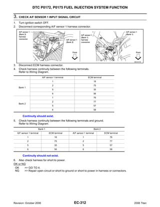


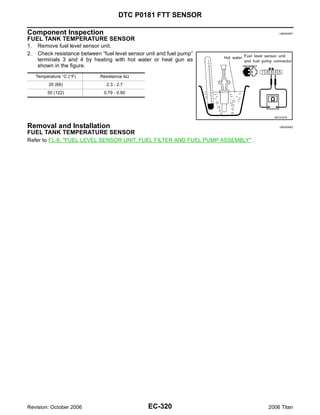


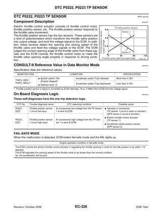


![DTC P0222, P0223 TP SENSOR
Specification data are reference values and are measured between each terminal and ground.
CAUTION: A
Do not use ECM ground terminals when measuring input/output voltage. Doing so may result in dam-
age to the ECM's transistor. Use a ground other than ECM terminals, such as the ground.
TER- EC
WIRE
MINAL ITEM CONDITION DATA (DC Voltage)
COLOR
NO.
Sensor power supply C
47 Y [Ignition switch: ON] Approximately 5V
(Throttle position sensor)
[Ignition switch: ON]
G Engine: Stopped D
More than 0.36V
G Selector lever: D
G Accelerator pedal: Fully released
50 B Throttle position sensor 1
[Ignition switch: ON] E
G Engine: Stopped
Less than 4.75V
G Selector lever: D
G Accelerator pedal: Fully depressed F
[Engine is running]
Sensor ground
66 R G Warm-up condition Approximately 0V
(Throttle position sensor)
G Idle speed G
[Ignition switch: ON]
G Engine: Stopped
Less than 4.75V H
G Selector lever: D
G Accelerator pedal: Fully released
69 W Throttle position sensor 2
[Ignition switch: ON] I
G Engine: Stopped
More than 0.36V
G Selector lever: D
G Accelerator pedal: Fully depressed J
Sensor power supply
91 W/R [Ignition switch: ON] Approximately 5V
(APP sensor 2)
Diagnostic Procedure UBS00NFC
K
1. CHECK GROUND CONNECTIONS
1. Turn ignition switch OFF. L
2. Loosen and retighten three ground screws on the body.
Refer to EC-156, "Ground Inspection" .
M
BBIA0354E
OK or NG
OK >> GO TO 2.
NG >> Repair or replace ground connections.
Revision: October 2006 EC-329 2006 Titan](https://image.slidesharecdn.com/ec-110402131317-phpapp02/85/Ec-329-320.jpg)

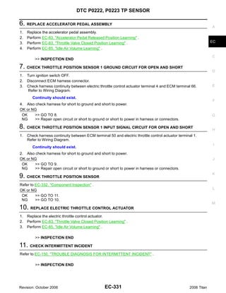


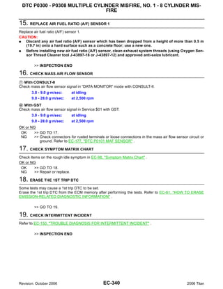


![DTC P0327, P0328, P0332, P0333 KS
Specification data are reference values and are measured between each terminal and ground.
CAUTION: A
Do not use ECM ground terminals when measuring input/output voltage. Doing so may result in dam-
age to the ECM's transistor. Use a ground other than ECM terminals, such as the ground.
TER- EC
WIRE
MINAL ITEM CONDITION DATA (DC Voltage)
COLOR
NO.
15 W Knock sensor (bank 1) [Engine is running] C
Approximately 2.5V
36 W Knock sensor (bank 2) G Idle speed
Diagnostic Procedure UBS00NFM
D
1. CHECK KNOCK SENSOR INPUT SIGNAL CIRCUIT FOR OPEN AND SHORT-I
1. Turn ignition switch OFF.
E
2. Disconnect ECM harness connector.
3. Check resistance between ECM terminals 15, 36 and ground. Refer to Wiring Diagram.
NOTE: F
It is necessary to use an ohmmeter which can measure more than 10 MΩ.
Resistance: Approximately 532 - 588 kΩ [at 20°C (68°F)]
4. Also check harness for short to ground and short to power. G
OK or NG
OK >> GO TO 5.
H
NG >> GO TO 2.
2. CHECK KNOCK SENSOR INPUT SIGNAL CIRCUIT FOR OPEN AND SHORT-II
I
1. Disconnect knock sensor harness connector.
2. Check harness continuity between ECM terminal 15 and knock
sensor (bank1) terminal 1, ECM terminal 36 and knock sensor J
(bank 2) terminal 1.
Refer to Wiring Diagram.
Continuity should exist. K
3. Also check harness for short to ground and short to power.
OK or NG
L
OK >> GO TO 4.
PBIB0021E
NG >> GO TO 3.
3. DETECT MALFUNCTIONING PART M
Check the following.
G Harness connectors F26, F101
G Harness for open or short between ECM and knock sensor
>> Repair open circuit or short to ground or short to power in harness or connectors.
4. CHECK KNOCK SENSOR
Refer to EC-345, "Component Inspection" .
OK or NG
OK >> GO TO 5.
NG >> Replace knock sensor.
Revision: October 2006 EC-343 2006 Titan](https://image.slidesharecdn.com/ec-110402131317-phpapp02/85/Ec-343-320.jpg)

![DTC P0327, P0328, P0332, P0333 KS
Component Inspection UBS00NFN
KNOCK SENSOR A
Check resistance between knock sensor terminal 1 and ground.
NOTE:
It is necessary to use an ohmmeter which can measure more EC
than 10 MΩ.
Resistance: Approximately 532 - 588 kΩ [at 20°C (68°F)]
C
CAUTION:
Do not use any knock sensors that have been dropped or phys-
ically damaged. Use only new ones.
D
SEF227W
Removal and Installation UBS00NFO
E
KNOCK SENSOR
Refer to EM-78, "CYLINDER BLOCK" .
F
G
H
I
J
K
L
M
Revision: October 2006 EC-345 2006 Titan](https://image.slidesharecdn.com/ec-110402131317-phpapp02/85/Ec-345-320.jpg)
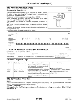


![DTC P0335 CKP SENSOR (POS)
Specification data are reference values and are measured between each terminal and ground.
Pulse signal is measured by CONSULT-II. A
CAUTION:
Do not use ECM ground terminals when measuring input/output voltage. Doing so may result in dam-
age to the ECM's transistor. Use a ground other than ECM terminals, such as the ground. EC
TER-
WIRE
MINAL ITEM CONDITION DATA (DC Voltage)
COLOR
NO.
C
1.0 - 2.0V
[Engine is running]
G Warm-up condition
D
G Idle speed
NOTE:
The pulse cycle changes depending on rpm at
idle. E
PBIB1041E
Crankshaft position sensor
13 O
(POS)
1.0 - 2.0V
F
[Engine is running]
G Engine speed: 2,000 rpm. G
PBIB1042E
H
[Engine is running]
[Ignition switch: OFF]
0 - 1.5V
G For a few seconds after turning ignition switch
ECM relay OFF I
111 W/B
(Self shut-off)
[Ignition switch: OFF]
BATTERY VOLTAGE
G More than a few seconds after turning ignition (11 - 14V)
switch OFF J
119 BR BATTERY VOLTAGE
Power supply for ECM [Ignition switch: ON]
120 BR (11 - 14V)
K
: Average voltage for pulse signal (Actual pulse signal can be confirmed by oscilloscope.)
Diagnostic Procedure UBS00NFU
1. CHECK GROUND CONNECTIONS L
1. Turn ignition switch OFF.
2. Loosen and retighten three ground screws on the body. M
Refer to EC-156, "Ground Inspection" .
BBIA0354E
OK or NG
OK >> GO TO 2.
NG >> Repair or replace ground connections.
Revision: October 2006 EC-349 2006 Titan](https://image.slidesharecdn.com/ec-110402131317-phpapp02/85/Ec-349-320.jpg)


![DTC P0335 CKP SENSOR (POS)
Component Inspection UBS00NFV
CRANKSHAFT POSITION SENSOR (POS)
1. Loosen the fixing bolt of the sensor.
2. Disconnect crankshaft position sensor (POS) harness connector.
3. Remove the sensor.
4. Visually check the sensor for chipping.
PBIB0563E
5. Check resistance as shown in the figure.
Terminal No. (Polarity) Resistance Ω [at 25°C (77°F)]
1 (+) - 2 (-)
1 (+) - 3 (-) Except 0 or ∞
2 (+) - 3 (-)
PBIB0564E
Removal and Installation UBS00NFW
CRANKSHAFT POSITION SENSOR (POS)
Refer to AT-264, "TRANSMISSION ASSEMBLY" .
Revision: October 2006 EC-352 2006 Titan](https://image.slidesharecdn.com/ec-110402131317-phpapp02/85/Ec-352-320.jpg)


![DTC P0340 CMP SENSOR (PHASE)
Specification data are reference values and are measured between each terminal and ground.
Pulse signal is measured by CONSULT-II.
CAUTION:
Do not use ECM ground terminals when measuring input/output voltage. Doing so may result in dam-
age to the ECM's transistor. Use a ground other than ECM terminals, such as the ground.
TER-
WIRE
MINAL ITEM CONDITION DATA (DC Voltage)
COLOR
NO.
1.0 - 4.0V
[Engine is running]
G Warm-up condition
G Idle speed
NOTE:
The pulse cycle changes depending on rpm at
idle.
PBIB1039E
Camshaft position sensor
14 Y
(PHASE)
1.0 - 4.0V
[Engine is running]
G Engine speed: 2,000 rpm.
PBIB1040E
[Engine is running]
[Ignition switch: OFF]
0 - 1.5V
G For a few seconds after turning ignition
ECM relay switch OFF
111 W/B
(Self shut-off)
[Ignition switch: OFF]
BATTERY VOLTAGE
G More than a few seconds after turning igni- (11 - 14V)
tion switch OFF
119 BR BATTERY VOLTAGE
Power supply for ECM [Ignition switch: ON]
120 BR (11 - 14V)
: Average voltage for pulse signal (Actual pulse signal can be confirmed by oscilloscope.)
Diagnostic Procedure UBS00NG1
1. CHECK STARTING SYSTEM
Turn ignition switch to START position.
Does the engine turn over?
Does the starter motor operate?
Yes or No
Yes >> GO TO 2.
No >> Check starting system. (Refer to SC-10, "STARTING SYSTEM" .)
Revision: October 2006 EC-356 2006 Titan](https://image.slidesharecdn.com/ec-110402131317-phpapp02/85/Ec-356-320.jpg)


![DTC P0340 CMP SENSOR (PHASE)
Component Inspection UBS00NG2
CAMSHAFT POSITION SENSOR (PHASE) A
1. Loosen the fixing bolt of the sensor.
2. Disconnect camshaft position sensor (PHASE) harness connector.
3. Remove the sensor. EC
4. Visually check the sensor for chipping.
C
D
E
PBIB0563E
F
5. Check resistance as shown in the figure.
Terminal No. (Polarity) Resistance Ω [at 25°C (77°F)]
3(+) - 1 (-) G
2 (+) - 1 (-) Except 0 or ∞
3 (+) - 2 (-)
H
I
PBIB0564E
Removal and Installation UBS00NG3
CAMSHAFT POSITION SENSOR (PHASE) J
Refer to EM-46, "CAMSHAFT" .
K
L
M
Revision: October 2006 EC-359 2006 Titan](https://image.slidesharecdn.com/ec-110402131317-phpapp02/85/Ec-359-320.jpg)

![DTC P0420, P0430 THREE WAY CATALYST FUNCTION
8. Select “DTC & SRT CONFIRMATION” then “SRT WORK SUP-
PORT” mode with CONSULT-II. A
9. Rev engine up to 2,000 to 3,000 rpm and hold it for 3 consecu-
tive minutes then release the accelerator pedal completely.
If “INCMP” of “CATALYST” changed to “CMPLT”, go to step 12. EC
10. Wait 5 seconds at idle.
C
PBIB1784E
D
11. Rev engine up to 2,000 to 3,000 rpm and maintain it until
“INCMP” of “CATALYST” changes to “CMPLT” (It will take
approximately 5 minutes). E
If not “CMPLT”, stop engine and cool it down to less than 70°C
(158°F) and then retest from step 1.
F
G
PBIB1785E
12. Select “SELF-DIAG RESULTS” mode with CONSULT-II. H
13. Confirm that the 1st trip DTC is not detected.
If the 1st trip DTC is detected, go to EC-362, "Diagnostic Proce-
dure" . I
J
SEF535Z K
Overall Function Check UBS00NG6
Use this procedure to check the overall function of the three way catalyst (manifold). During this check, a 1st L
trip DTC might not be confirmed.
WITH GST
1. Start engine and warm it up to the normal operating temperature. M
2. Turn ignition switch OFF and wait at least 10 seconds.
3. Start engine and keep the engine speed between 3,500 and 4,000 rpm for at least 1 minute under no load.
4. Let engine idle for 1 minute.
5. Open engine hood.
6. Set voltmeter probe between ECM terminals ECM terminals 55
[HO2S2 (bank 1) signal], 74 [HO2S2 (bank 2) signal] and
ground.
7. Keep engine speed at 2,500 rpm constant under no load.
8. Make sure that the voltage does not vary for more than 5 sec-
onds.
If the voltage fluctuation cycle takes less than 5 seconds, go to
EC-362, "Diagnostic Procedure" .
G 1 cycle: 0.6 - 1.0 → 0 - 0.3 → 0.6 - 1.0
PBIB2056E
Revision: October 2006 EC-361 2006 Titan](https://image.slidesharecdn.com/ec-110402131317-phpapp02/85/Ec-361-320.jpg)

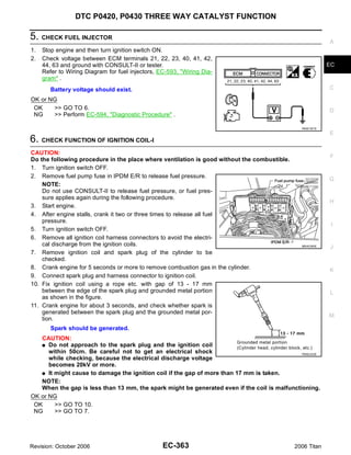
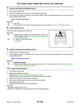


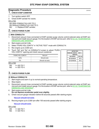
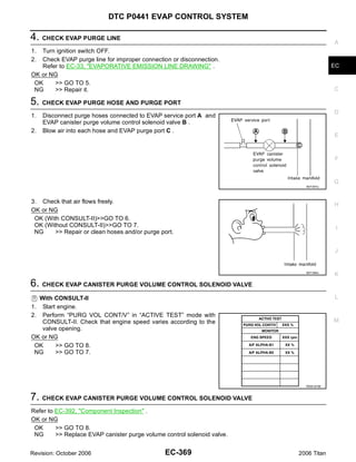

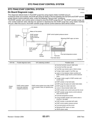


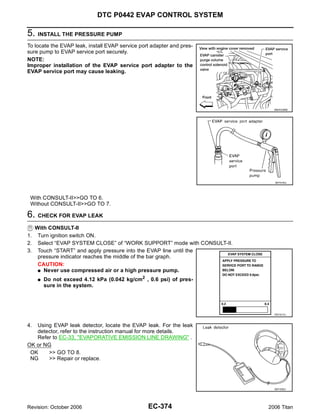


![DTC P0443 EVAP CANISTER PURGE VOLUME CONTROL SOLENOID VALVE
Specification data are reference values and are measured between each terminal and ground.
Pulse signal is measured by CONSULT-II.
CAUTION:
Do not use ECM ground terminals when measuring input/output voltage. Doing so may result in dam-
age to the ECM's transistor. Use a ground other than ECM terminals, such as the ground.
TER-
WIRE
MINAL ITEM CONDITION DATA (DC Voltage)
COLOR
NO.
BATTERY VOLTAGE
(11 - 14V)
[Engine is running]
G Idle speed
G Accelerator pedal: Not depressed even
slightly, after starting engine
EVAP canister purge vol-
45 L/Y PBIB0050E
ume control solenoid valve
11 - 14V
[Engine is running]
G Engine speed: About 2,000 rpm (More than
100 seconds after starting engine).
PBIB0051E
[Engine is running]
[Ignition switch: OFF]
0 - 1.5V
G For a few seconds after turning ignition
ECM relay switch OFF
111 W/B
(Self shut-off)
[Ignition switch: OFF]
BATTERY VOLTAGE
G More than a few seconds after turning igni- (11 - 14V)
tion switch OFF
119 BR BATTERY VOLTAGE
Power supply for ECM [Ignition switch: ON]
120 BR (11 - 14V)
: Average voltage for pulse signal (Actual pulse signal can be confirmed by oscilloscope.)
Revision: October 2006 EC-382 2006 Titan](https://image.slidesharecdn.com/ec-110402131317-phpapp02/85/Ec-382-320.jpg)


![DTC P0444, P0445 EVAP CANISTER PURGE VOLUME CONTROL SOLENOID
VALVE
Specification data are reference values and are measured between each terminal and ground.
Pulse signal is measured by CONSULT-II.
CAUTION:
Do not use ECM ground terminals when measuring input/output voltage. Doing so may result in dam-
age to the ECM's transistor. Use a ground other than ECM terminals, such as the ground.
TER-
WIRE
MINAL ITEM CONDITION DATA (DC Voltage)
COLOR
NO.
BATTERY VOLTAGE
(11 - 14V)
[Engine is running]
G Idle speed
G Accelerator pedal: Not depressed even
slightly, after starting engine.
EVAP canister purge vol-
45 L/Y PBIB0050E
ume control solenoid valve
11 - 14V
[Engine is running]
G Engine speed: About 2,000 rpm (More than
100 seconds after starting engine)
PBIB0051E
[Engine is running]
[Ignition switch: OFF]
0 - 1.5V
G For a few seconds after turning ignition
ECM relay switch OFF
111 W/B
(Self shut-off)
[Ignition switch: OFF]
BATTERY VOLTAGE
G More than a few seconds after turning igni- (11 - 14V)
tion switch OFF
119 BR BATTERY VOLTAGE
Power supply for ECM [Ignition switch: ON]
120 BR (11 - 14V)
: Average voltage for pulse signal (Actual pulse signal can be confirmed by oscilloscope.)
Revision: October 2006 EC-390 2006 Titan](https://image.slidesharecdn.com/ec-110402131317-phpapp02/85/Ec-390-320.jpg)


![DTC P0447 EVAP CANISTER VENT CONTROL VALVE
Specification data are reference values and are measured between each terminal and ground.
CAUTION: A
Do not use ECM ground terminals when measuring input/output voltage. Doing so may result in dam-
age to the ECM's transistor. Use a ground other than ECM terminals, such as the ground.
TER- EC
WIRE
MINAL ITEM CONDITION DATA (DC Voltage)
COLOR
NO.
[Engine is running] C
[Ignition switch: OFF]
0 - 1.5V
G For a few seconds after turning ignition
ECM relay switch OFF
111 W/B
(Self shut-off) D
[Ignition switch: OFF]
BATTERY VOLTAGE
G More than a few seconds after turning igni- (11 - 14V)
tion switch OFF
E
EVAP canister vent control BATTERY VOLTAGE
117 L/Y [Ignition switch: ON]
valve (11 - 14V)
Diagnostic Procedure UBS00NH1 F
1. INSPECTION START
Do you have CONSULT-II? G
Yes or No
Yes >> GO TO 2.
No >> GO TO 3. H
2. CHECK EVAP CANISTER VENT CONTROL VALVE CIRCUIT
I
With CONSULT-II
1. Turn ignition switch OFF and then turn ON.
2. Select “VENT CONTROL/V” in “ACTIVE TEST” mode with CONSULT-II. J
3. Touch “ON/OFF” on CONSULT-II screen.
4. Check for operating sound of the valve.
Clicking noise should be heard. K
OK or NG
OK >> GO TO 7.
NG >> GO TO 3. L
M
PBIB1679E
Revision: October 2006 EC-397 2006 Titan](https://image.slidesharecdn.com/ec-110402131317-phpapp02/85/Ec-397-320.jpg)


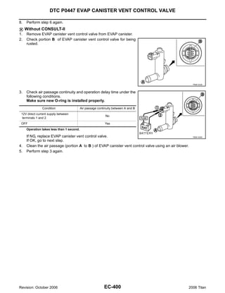
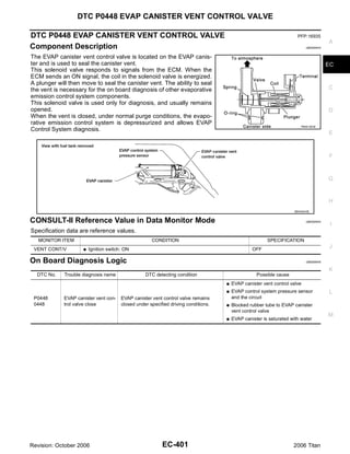


![DTC P0448 EVAP CANISTER VENT CONTROL VALVE
Specification data are reference values and are measured between each terminal and ground.
CAUTION:
Do not use ECM ground terminals when measuring input/output voltage. Doing so may result in dam-
age to the ECM's transistor. Use a ground other than ECM terminals, such as the ground.
TER-
WIRE
MINAL ITEM CONDITION DATA (DC Voltage)
COLOR
NO.
[Engine is running]
[Ignition switch: OFF]
0 - 1.5V
G For a few seconds after turning ignition
ECM relay switch OFF
111 W/B
(Self shut-off)
[Ignition switch: OFF]
BATTERY VOLTAGE
G More than a few seconds after turning igni- (11 - 14V)
tion switch OFF
EVAP canister vent control BATTERY VOLTAGE
117 L/Y [Ignition switch: ON]
valve (11 - 14V)
Diagnostic Procedure UBS00NH8
1. CHECK RUBBER TUBE
1. Turn ignition switch OFF.
2. Disconnect rubber tube connected to EVAP canister vent control valve.
BBIA0443E
3. Check the rubber tube for clogging.
OK or NG
OK >> GO TO 2.
NG >> Clean rubber tube using an air blower.
2. CHECK EVAP CANISTER VENT CONTROL VALVE
Refer to EC-406, "Component Inspection" .
OK or NG
OK >> GO TO 3.
NG >> Replace EVAP canister vent control valve.
Revision: October 2006 EC-404 2006 Titan](https://image.slidesharecdn.com/ec-110402131317-phpapp02/85/Ec-404-320.jpg)


![DTC P0452 EVAP CONTROL SYSTEM PRESSURE SENSOR
Specification data are reference values and are measured between each terminal and ground.
CAUTION:
Do not use ECM ground terminals when measuring input/output voltage. Doing so may result in dam-
age to the ECM's transistor. Use a ground other than ECM terminals, such as the ground.
TER-
WIRE
MINAL ITEM CONDITION DATA (DC Voltage)
COLOR
NO.
EVAP control system pressure
32 L [Ignition switch: ON] Approximately 1.8 - 4.8V
sensor
Sensor power supply
48 SB (EVAP control system pressure [Ignition switch: ON] Approximately 5V
sensor)
[Engine is running]
67 B Sensor ground G Warm-up condition Approximately 0V
G Idle speed
Diagnostic Procedure UBS00NHL
1. CHECK GROUND CONNECTIONS
1. Turn ignition switch OFF.
2. Loosen and retighten three ground screws on the body.
Refer to EC-156, "Ground Inspection" .
BBIA0354E
OK or NG
OK >> GO TO 2.
NG >> Repair or replace ground connections.
2. CHECK CONNECTOR
1. Disconnect EVAP control system pressure sensor harness connector.
BBIA0443E
2. Check sensor harness connector for water.
Water should not exist.
OK or NG
OK >> GO TO 3.
NG >> Repair or replace harness connector.
Revision: October 2006 EC-414 2006 Titan](https://image.slidesharecdn.com/ec-110402131317-phpapp02/85/Ec-414-320.jpg)
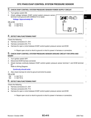


![DTC P0453 EVAP CONTROL SYSTEM PRESSURE SENSOR
Specification data are reference values and are measured between each terminal and ground.
CAUTION:
Do not use ECM ground terminals when measuring input/output voltage. Doing so may result in dam-
age to the ECM's transistor. Use a ground other than ECM terminals, such as the ground.
TER-
WIRE
MINAL ITEM CONDITION DATA (DC Voltage)
COLOR
NO.
EVAP control system pressure
32 L [Ignition switch: ON] Approximately 1.8 - 4.8V
sensor
Sensor power supply
48 SB (EVAP control system pressure [Ignition switch: ON] Approximately 5V
sensor)
[Engine is running]
67 B Sensor ground G Warm-up condition Approximately 0V
G Idle speed
Diagnostic Procedure UBS00NHS
1. CHECK GROUND CONNECTIONS
1. Turn ignition switch OFF.
2. Loosen and retighten three ground screws on the body.
Refer to EC-156, "Ground Inspection" .
BBIA0354E
OK or NG
OK >> GO TO 2.
NG >> Repair or replace ground connections.
2. CHECK CONNECTOR
1. Disconnect EVAP control system pressure sensor harness connector.
BBIA0443E
2. Check sensor harness connector for water.
Water should not exist.
OK or NG
OK >> GO TO 3.
NG >> Repair or replace harness connector.
Revision: October 2006 EC-420 2006 Titan](https://image.slidesharecdn.com/ec-110402131317-phpapp02/85/Ec-420-320.jpg)


![DTC P0455 EVAP CONTROL SYSTEM
DTC Confirmation Procedure UBS00NHV
CAUTION:
Never remove fuel filler cap during the DTC Confirmation Procedure.
NOTE:
G Make sure that EVAP hoses are connected to EVAP canister purge volume control solenoid valve
properly.
G If DTC Confirmation Procedure has been previously conducted, always turn ignition switch OFF and wait
at least 10 seconds before conducting the next test.
TESTING CONDITION:
G Perform “DTC WORK SUPPORT” when the fuel level is between 1/4 and 3/4 full, and vehicle is
placed on flat level surface.
G Open engine hood before conducting the following procedures.
WITH CONSULT-II
1. Tighten fuel filler cap securely until ratcheting sound is heard.
2. Turn ignition switch ON.
3. Turn ignition switch OFF and wait at least 10 seconds.
4. Turn ignition switch ON and select “DATA MONITOR” mode with CONSULT-II.
5. Make sure that the following conditions are met.
COOLAN TEMP/S: 0 - 70°C (32 - 158°F)
INT/A TEMP SE: 0 - 60°C (32 - 140°F)
6. Select “EVP SML LEAK P0442/P1442” of “EVAPORATIVE SYSTEM” in “DTC WORK SUPPORT” mode
with CONSULT-II.
Follow the instruction displayed.
PBIB0829E
NOTE:
If the engine speed cannot be maintained within the range displayed on the CONSULT-II screen, go to
EC-71, "Basic Inspection" .
7. Make sure that “OK” is displayed.
If “NG” is displayed, select “SELF-DIAG RESULTS” mode and
make sure that “EVAP GROSS LEAK [P0455]” is displayed. If it
is displayed, refer to EC-427, "Diagnostic Procedure" .
If P0442 is displayed, perform Diagnostic Procedure for DTC
P0442, EC-373, "Diagnostic Procedure" .
SEC763C
Revision: October 2006 EC-426 2006 Titan](https://image.slidesharecdn.com/ec-110402131317-phpapp02/85/Ec-426-320.jpg)
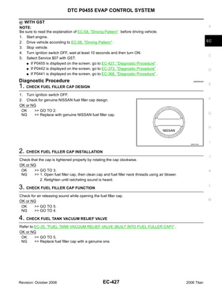


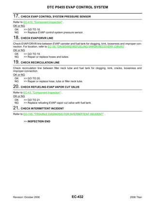


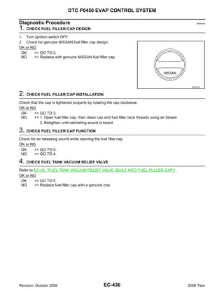


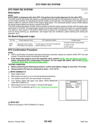


![DTC P0550 PSP SENSOR
Specification data are reference values and are measured between each terminal and ground.
CAUTION:
Do not use ECM ground terminals when measuring input/output voltage. Doing so may result in dam-
age to the ECM's transistor. Use a ground other than ECM terminals, such as the ground.
TER-
WIRE
MINAL ITEM CONDITION DATA (DC Voltage)
COLOR
NO.
[Engine is running]
0.5 - 4.5V
Power steering pressure G Steering wheel: Being turned.
12 R
sensor [Engine is running]
0.4 - 0.8V
G Steering wheel: Not being turned.
[Engine is running]
67 B Sensor ground G Warm-up condition Approximately 0V
G Idle speed
Sensor power supply
68 W/L (Power steering pressure [Ignition switch: ON] Approximately 5V
sensor)
Diagnostic Procedure UBS00NIY
1. CHECK GROUND CONNECTIONS
1. Turn ignition switch OFF.
2. Loosen and retighten three ground screws on the body.
Refer to EC-156, "Ground Inspection" .
BBIA0354E
OK or NG
OK >> GO TO 2.
NG >> Repair or replace ground connections.
Revision: October 2006 EC-456 2006 Titan](https://image.slidesharecdn.com/ec-110402131317-phpapp02/85/Ec-456-320.jpg)


![DTC P0603 ECM POWER SUPPLY
DTC P0603 ECM POWER SUPPLY PFP:23710
A
Component Description UBS00NJ1
Battery voltage is supplied to the ECM even when the ignition switch
is turned OFF for the ECM memory function of the DTC memory, the EC
air-fuel ratio feedback compensation value memory, the idle air vol-
ume learning value memory, etc.
C
D
PBIB1164E
E
On Board Diagnosis Logic UBS00NJ2
DTC No. Trouble diagnosis name DTC detecting condition Possible cause
F
G Harness or connectors
P0603 ECM back-up RAM system does not function [ECM power supply (back-up) circuit is
ECM power supply circuit open or shorted.]
0603 properly.
G ECM G
DTC Confirmation Procedure UBS00NJ3
NOTE: H
If DTC Confirmation Procedure has been previously conducted, always turn ignition switch OFF and wait at
least 10 seconds before conducting the next test.
WITH CONSULT-II I
1. Turn ignition switch ON and wait at least 1 second.
2. Select “DATA MONITOR” mode with CONSULT-II.
3. Start engine and let it idle for 1 second. J
4. Turn ignition switch OFF, wait at least 10 seconds and then turn
ON.
5. Repeat steps 3 and 4 for 4 times. K
6. If 1st trip DTC is detected, go to EC-461, "Diagnostic Procedure"
.
L
SEF058Y
M
WITH GST
Follow the procedure “WITH CONSULT-II” above.
Revision: October 2006 EC-459 2006 Titan](https://image.slidesharecdn.com/ec-110402131317-phpapp02/85/Ec-459-320.jpg)

![DTC P0603 ECM POWER SUPPLY
Specification data are reference values and are measured between each terminal and ground.
CAUTION: A
Do not use ECM ground terminals when measuring input/output voltage. Doing so may result in dam-
age to the ECM's transistor. Use a ground other than ECM terminals, such as the ground.
TER- EC
WIRE
MINAL ITEM CONDITION DATA (DC Voltage)
COLOR
NO.
Power supply for ECM BATTERY VOLTAGE C
121 W [Ignition switch: OFF]
(Back-up) (11 - 14V)
Diagnostic Procedure UBS00NJ5
D
1. CHECK ECM POWER SUPPLY
1. Turn ignition switch OFF.
2. Disconnect ECM harness connector. E
3. Check voltage between ECM terminal 121 and ground with
CONSULT-II or tester.
F
Voltage: Battery voltage
OK or NG
OK >> GO TO 3. G
NG >> GO TO 2.
H
MBIB0026E
2. DETECT MALFUNCTIONING PART I
Check the following.
G IPDM E/R connector E121 J
G 20A fuse
G Harness for open or short between ECM and battery
K
>> Repair or replace harness or connectors.
3. CHECK INTERMITTENT INCIDENT L
Refer to EC-150, "TROUBLE DIAGNOSIS FOR INTERMITTENT INCIDENT" .
OK or NG M
OK >> GO TO 4.
NG >> Repair or replace harness or connectors.
Revision: October 2006 EC-461 2006 Titan](https://image.slidesharecdn.com/ec-110402131317-phpapp02/85/Ec-461-320.jpg)


![DTC P0643 SENSOR POWER SUPPLY
Specification data are reference values and are measured between each terminal and ground.
CAUTION:
Do not use ECM ground terminals when measuring input/output voltage. Doing so may result in dam-
age to the ECM's transistor. Use a ground other than ECM terminals, such as the ground.
TER-
WIRE
MINAL ITEM CONDITION DATA (DC Voltage)
COLOR
NO.
Sensor power supply
48 SB (EVAP control system [Ignition switch: ON] Approximately 5V
pressure sensor)
Sensor power supply
49 R/Y (Refrigerant pressure [Ignition switch: ON] Approximately 5V
sensor)
Sensor power supply
68 W/L (Power steering pressure [Ignition switch: ON] Approximately 5V
sensor)
[Engine is running]
Sensor ground
82 B/R G Warm-up condition Approximately 0V
(APP sensor 1)
G Idle speed
[Engine is running]
Sensor ground
83 G/W G Warm-up condition Approximately 0V
(APP sensor 2)
G Idle speed
Sensor power supply
90 L [Ignition switch: ON] Approximately 5V
(APP sensor 1)
Sensor power supply
91 W/R [Ignition switch: ON] Approximately 5V
(APP sensor 2)
[Ignition switch: ON]
G Engine: Stopped 0.25 - 0.50V
Accelerator pedal position G Accelerator pedal: Fully released
98 G/R
sensor 2 [Ignition switch: ON]
G Engine: Stopped 2.0 - 2.5V
G Accelerator pedal: Fully depressed
[Ignition switch: ON]
G Engine: Stopped 0.5 - 1.0V
Accelerator pedal position G Accelerator pedal: Fully released
106 BR/W
sensor 1 [Ignition switch: ON]
G Engine: Stopped 4.2 - 4.8V
G Accelerator pedal: Fully depressed
Revision: October 2006 EC-468 2006 Titan](https://image.slidesharecdn.com/ec-110402131317-phpapp02/85/Ec-468-320.jpg)


![DTC P0850 PNP SWITCH
DTC P0850 PNP SWITCH PFP:23006
A
Component Description UBS00NJE
When the gear position is P or N, park/neutral position (PNP) switch is ON.
TCM detects the position because the continuity of the line (the ON signal) exists. EC
Then the TCM sends the PNP switch signal to the ECM via combination meter.
CONSULT-II Reference Value in Data Monitor Mode UBS00NJF
C
Specification data are reference values.
MONITOR ITEM CONDITION SPECIFICATION
Selector lever: P or N ON D
P/N POSI SW G Ignition switch: ON
Selector lever: Except above OFF
On Board Diagnosis Logic UBS00NJG
E
DTC No. Trouble diagnosis name DTC detecting condition Possible cause
G Harness or connectors
[The park/neutral position (PNP) switch
F
The signal of the park/neutral position (PNP) circuit is open or shorted.]
P0850 Park/neutral position
switch is not changed in the process of engine G Park/neutral position (PNP) switch
0850 switch
starting and driving.
G Combination meter G
G TCM
DTC Confirmation Procedure UBS00NJH H
CAUTION:
Always drive vehicle at a safe speed.
NOTE: I
If DTC Confirmation Procedure has been previously conducted, always turn ignition switch OFF and wait at
least 10 seconds before conducting the next test.
WITH CONSULT-II J
1. Turn ignition switch ON.
2. Select “P/N POSI SW” in “DATA MONITOR” mode with CON-
SULT-II. Then check the “P/N POSI SW” signal under the follow- K
ing conditions.
Position (Selector lever) Known-good signal
L
N or P position ON
Except the above position OFF
M
If NG, go to EC-474, "Diagnostic Procedure" .
If OK, go to following step.
SEF212Y
3. Select “DATA MONITOR” mode with CONSULT-II.
4. Start engine and warm it up to normal operating temperature.
5. Maintain the following conditions for at least 60 consecutive sec-
onds.
ENG SPEED More than 1,000 rpm
COOLAN TEMP/S More than 70°C (158°F)
B/FUEL SCHDL More than 2.0 msec
VHCL SPEED SE More than 64 km/h (40 MPH)
Selector lever Suitable position SEF213Y
6. If 1st trip DTC is detected, go to EC-474, "Diagnostic Procedure" .
Revision: October 2006 EC-471 2006 Titan](https://image.slidesharecdn.com/ec-110402131317-phpapp02/85/Ec-471-320.jpg)
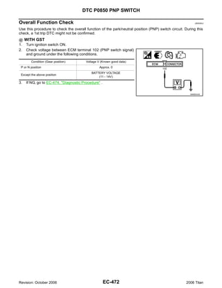

![DTC P0850 PNP SWITCH
Specification data are reference values and are measured between each terminal and ground.
CAUTION:
Do not use ECM ground terminals when measuring input/output voltage. Doing so may result in dam-
age to the ECM's transistor. Use a ground other than ECM terminals, such as the ground.
TER-
WIRE
MINAL ITEM CONDITION DATA (DC Voltage)
COLOR
NO.
[Ignition switch: ON]
Approximately 0V
G Selector lever: P or N
102 GR/R PNP switch
[Ignition switch: ON] BATTERY VOLTAGE
G Except the above gear position (11 - 14V)
Diagnostic Procedure UBS00NJK
1. CHECK DTC WITH TCM
Refer to AT-41, "OBD-II Diagnostic Trouble Code (DTC)" .
OK or NG
OK >> GO TO 2.
NG >> Repair or replace.
2. CHECK STARTING SYSTEM
Turn ignition switch OFF, then turn it to START.
Does starter motor operate?
Yes or No
Yes >> GO TO 3.
No >> Refer to SC-10, "STARTING SYSTEM" .
3. CHECK PNP SWITCH INPUT SIGNAL CIRCUIT FOR OPEN AND SHORT-I
1. Turn ignition switch OFF.
2. Disconnect A/T assembly harness connector.
3. Disconnect combination meter harness connector.
4. Check harness continuity between A/T assembly terminal 9 and combination meter terminal 39.
Refer to Wiring Diagram.
Continuity should exist.
5. Also check harness for short to ground and short to power.
OK or NG
OK >> GO TO 5.
NG >> GO TO 4.
4. DETECT MALFUNCTIONING PART
Check the following.
G Harness connectors F14, E5
G Harness connectors E152, M31
G Harness for open or short between A/T assembly and combination meter
>> Repair open circuit or short to ground or short to power in harness or connectors.
Revision: October 2006 EC-474 2006 Titan](https://image.slidesharecdn.com/ec-110402131317-phpapp02/85/Ec-474-320.jpg)

![DTC P1148, P1168 CLOSED LOOP CONTROL
DTC P1148, P1168 CLOSED LOOP CONTROL PFP:22690
On Board Diagnosis Logic UBS00NJL
These self-diagnoses have the one trip detection logic.
DTC No. Trouble diagnosis name DTC detecting condition Possible cause
P1148 The closed loop control function for bank 1
G Harness or connectors
1148 does not operate even when vehicle is driving
[The air fuel ratio (A/F) sensor 1 circuit is
(Bank 1) Closed loop control in the specified condition.
open or shorted.]
P1168 function The closed loop control function for bank 2 G Air fuel ratio (A/F) sensor 1
1168 does not operate even when vehicle is driving
G Air fuel ratio (A/F) sensor 1 heater
(Bank 2) in the specified condition.
DTC P1148 or P1168 is displayed with another DTC for air fuel ratio (A/F) sensor 1.
Perform the trouble diagnosis for the corresponding DTC.
Revision: October 2006 EC-476 2006 Titan](https://image.slidesharecdn.com/ec-110402131317-phpapp02/85/Ec-476-320.jpg)

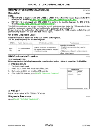
![DTC P1217 ENGINE OVER TEMPERATURE
DTC P1217 ENGINE OVER TEMPERATURE PFP:00000
A
Description UBS00NJU
SYSTEM DESCRIPTION
NOTE: EC
G If DTC P1217 is displayed with DTC U1000 or U1001, first perform the trouble diagnosis for DTC
U1000, U1001. Refer to EC-157, "DTC U1000, U1001 CAN COMMUNICATION LINE" .
G If DTC P1217 is displayed with DTC U1010, first perform the trouble diagnosis for DTC U1010.
Refer to EC-160, "DTC U1010 CAN COMMUNICATION" . C
Cooling Fan Control
Sensor Input signal to ECM ECM function Actuator D
Crankshaft position sensor (POS)
Camshaft position sensor (PHASE) Engine speed*1
Battery Battery voltage*1 E
Wheel sensor Vehicle speed*2 Cooling fan IPDM E/R
control (Cooling fan relay)
Engine coolant temperature sensor Engine coolant temperature F
Air conditioner switch 2
Air conditioner ON signal*
Refrigerant pressure sensor Refrigerant pressure
G
*1: The ECM determines the start signal status by the signals of engine speed and battery voltage.
*2: This signal is sent to ECM through CAN communication line.
The ECM controls the cooling fan corresponding to the vehicle speed, engine coolant temperature, refrigerant H
pressure, and air conditioner ON signal. The control system has 2-step control [HI/OFF].
Cooling Fan Operation
I
J
K
L
M
PBIB2060E
CONSULT-II Reference Value in Data Monitor Mode UBS00NJV
Specification data are reference values.
MONITOR ITEM CONDITION SPECIFICATION
Engine coolant temperature: 99°C
OFF
G Engine: After warming up, idle (210°F) or less
COOLING FAN
the engine Engine coolant temperature: 100°C
HI
(212°F) or more
Revision: October 2006 EC-479 2006 Titan](https://image.slidesharecdn.com/ec-110402131317-phpapp02/85/Ec-479-320.jpg)


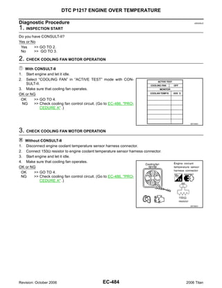
![DTC P1217 ENGINE OVER TEMPERATURE
4. CHECK COOLING SYSTEM FOR LEAK A
Apply pressure to the cooling system with a tester, and check if the
pressure drops.
EC
Testing pressure: 157 kPa (1.6 kg/cm2 , 23 psi)
CAUTION:
Higher than the specified pressure may cause radiator damage.
C
Pressure should not drop.
OK or NG
OK >> GO TO 5. D
NG >> Check the following for leak. Refer to CO-10, "CHECK-
ING COOLING SYSTEM FOR LEAKS" . PBIC1528E
G Hose
E
G Radiator
G Radiator cap
G Water pump F
G Reservoir tank
5. CHECK RESERVOIR TANK CAP
G
Apply pressure to cap with a tester.
Reservoir tank cap 95 - 125 kPa (0.97 - 1.28 kg/cm2 , H
relief pressure: 14 - 18 psi)
OK or NG
OK >> GO TO 6. I
NG >> Replace radiator cap.
J
SLC755A
6. CHECK THERMOSTAT K
1. Check valve seating condition at normal room temperatures.
It should seat tightly.
L
2. Check valve opening temperature and valve lift.
Valve opening temperature: 82°C (180°F) [standard]
Valve lift: More than 10.0 mm/95°C M
(0.394 in/203°F)
3. Check if valve is closed at 5°C (9°F) below valve opening tem-
perature.
For details, refer to CO-21, "THERMOSTAT AND WATER PIP-
ING" .
OK or NG
SLC343
OK >> GO TO 7.
NG >> Replace thermostat
7. CHECK ENGINE COOLANT TEMPERATURE SENSOR
Refer to EC-202, "Component Inspection" .
OK or NG
OK >> GO TO 8.
NG >> Replace engine coolant temperature sensor.
Revision: October 2006 EC-485 2006 Titan](https://image.slidesharecdn.com/ec-110402131317-phpapp02/85/Ec-485-320.jpg)
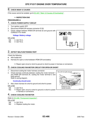


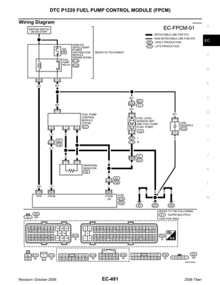
![DTC P1220 FUEL PUMP CONTROL MODULE (FPCM)
Specification data are reference values and are measured between each terminal and ground.
CAUTION:
Do not use ECM ground terminals when measuring input/output voltage. Doing so may result in dam-
age to the ECM's transistor. Use a ground other than ECM terminals, such as the ground.
TER-
WIRE
MINAL ITEM CONDITION DATA (DC Voltage)
COLOR
NO.
[Ignition switch: ON]
G More than a few seconds after turning igni- Approximately 0V
tion switch ON
[Ignition switch: ON]
Fuel pump control module
38 L G For a few seconds after turning ignition
(FPCM) check
switch ON
4 - 6V
[Engine is running]
G Warm-up condition
G Idle speed
[When cranking engine] 0 - 0.5V
Fuel pump control module [Engine is running]
39 L/Y
(FPCM) G Warm-up condition 8 - 12V
G Idle speed
[Ignition switch: ON]
G For 1 second after turning ignition switch ON 0 - 1.5V
[Engine is running]
113 GR Fuel pump relay
[Ignition switch: ON]
BATTERY VOLTAGE
G More than 1 second after turning ignition (11 - 14V)
switch ON
Diagnostic Procedure UBS00NK7
1. CHECK GROUND CONNECTIONS
1. Turn ignition switch OFF.
2. Loosen and retighten three ground screws on the body.
Refer to EC-156, "Ground Inspection" .
BBIA0354E
OK or NG
OK >> GO TO 2.
NG >> Repair or replace ground connections.
Revision: October 2006 EC-492 2006 Titan](https://image.slidesharecdn.com/ec-110402131317-phpapp02/85/Ec-492-320.jpg)

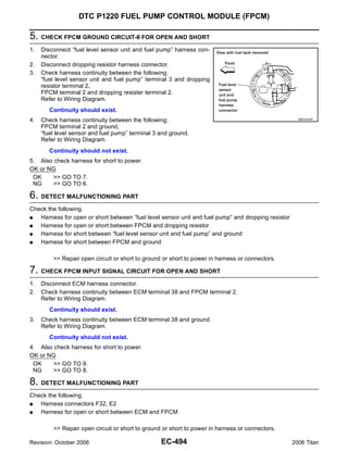


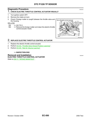


![DTC P1564 ASCD STEERING SWITCH
Specification data are reference values and are measured between each terminal and ground.
CAUTION:
Do not use ECM ground terminals when measuring input/output voltage. Doing so may result in dam-
age to the ECM's transistor. Use a ground other than ECM terminals, such as the ground.
TER-
WIRE
MINAL ITEM CONDITION DATA (DC Voltage)
COLOR
NO.
[Engine is running]
67 B Sensor ground G Warm-up condition Approximately 0V
G Idle speed
[Ignition switch: ON]
Approximately 4V
G ASCD steering switch: OFF
[Ignition switch: ON]
Approximately 0V
G MAIN switch: ON
[Ignition switch: ON]
99 G/Y ASCD steering switch Approximately 1V
G CANCEL switch: ON
[Ignition switch: ON]
Approximately 3V
G RESUME/ACCELERATTTE switch: ON
[Ignition switch: ON]
Approximately 2V
G SET/COAST switch: ON
Diagnostic Procedure UBS00NKO
1. CHECK GROUND CONNECTIONS
1. Turn ignition switch OFF.
2. Loosen and retighten three ground screws on the body.
Refer to EC-156, "Ground Inspection" .
BBIA0354E
OK or NG
OK >> GO TO 2.
NG >> Repair or replace ground connections.
Revision: October 2006 EC-504 2006 Titan](https://image.slidesharecdn.com/ec-110402131317-phpapp02/85/Ec-504-320.jpg)
![DTC P1564 ASCD STEERING SWITCH
2. CHECK ASCD STEERING SWITCH CIRCUIT A
With CONSULT-II
1. Turn ignition switch ON.
EC
2. Select “MAIN SW”, “CANCEL SW”, “RESUME/ACC SW” and “SET SW” in “DATA MONITOR” mode with
CONSULT-II.
3. Check each item indication under the following conditions.
C
Switch Monitor item Condition Indication
Pressed ON
MAIN switch MAIN SW
Released OFF D
Pressed ON
CANCEL switch CANCEL SW
Released OFF
E
RESUME/ACCELERATE Pressed ON
RESUME/ACC SW
switch Released OFF
SEC006D
Pressed ON F
SET/COAST switch SET SW
Released OFF
Without CONSULT-II G
1. Turn ignition switch ON.
2. Check voltage between ECM terminal 99 and ground with press-
H
ing each button.
Switch Condition Voltage [V]
Pressed Approx. 0 I
MAIN switch
Released Approx. 4
Pressed Approx. 1
CANCEL switch J
Released Approx. 4
RESUME/ACCELERATE Pressed Approx. 3
switch Released Approx. 4 PBIB0311E
K
Pressed Approx. 2
SET/COAST switch
Released Approx. 4
L
OK or NG
OK >> GO TO 8.
NG >> GO TO 3.
M
3. CHECK ASCD STEERING SWITCH GROUND CIRCUIT FOR OPEN AND SHORT
1. Turn ignition switch OFF.
2. Disconnect combination switch harness connector M102.
3. Disconnect ECM harness connector.
4. Check harness continuity between combination switch terminal
15 and ECM terminal 67.
Refer to Wiring Diagram.
Continuity should exist.
5. Also check harness for short to ground and short to power.
OK or NG
OK >> GO TO 5. BBIA0362E
NG >> GO TO 4.
Revision: October 2006 EC-505 2006 Titan](https://image.slidesharecdn.com/ec-110402131317-phpapp02/85/Ec-505-320.jpg)

![DTC P1564 ASCD STEERING SWITCH
Component Inspection UBS00NKP
ASCD STEERING SWITCH A
1. Disconnect combination switch (spiral cable) harness connector M102.
2. Check continuity between combination switch (spiral cable) ter-
minals 14 and 15 with pushing each switch. EC
Switch Condition Resistance [Ω]
Pressed Approx. 0 C
MAIN switch
Released Approx. 4,000
Pressed Approx. 250
CANCEL switch D
Released Approx. 4,000
RESUME/ACCELERATE Pressed Approx. 1,480
switch Released Approx. 4,000 PBIB1673E
E
Pressed Approx. 660
SET/COAST switch
Released Approx. 4,000
F
G
H
I
J
K
L
M
Revision: October 2006 EC-507 2006 Titan](https://image.slidesharecdn.com/ec-110402131317-phpapp02/85/Ec-507-320.jpg)

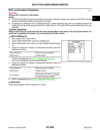

![DTC P1572 ASCD BRAKE SWITCH
Specification data are reference values and are measured between each terminal and ground.
CAUTION: A
Do not use ECM ground terminals when measuring input/output voltage. Doing so may result in dam-
age to the ECM's transistor. Use a ground other than ECM terminals, such as the ground.
TER- EC
WIRE
MINAL ITEM CONDITION DATA (DC Voltage)
COLOR
NO.
[Ignition switch: OFF] C
Approximately 0V
G Brake pedal: Fully released
101 R/W Stop lamp switch
[Ignition switch: OFF] BATTERY VOLTAGE
G Brake pedal: Slightly depressed (11 - 14V) D
[Ignition switch: ON] BATTERY VOLTAGE
G Brake pedal: Fully released (11 - 14V)
108 BR/W ASCD brake switch E
[Ignition switch: ON]
Approximately 0V
G Brake pedal: Slightly depressed
Diagnostic Procedure UBS00NKV F
1. CHECK OVERALL FUNCTION-I
With CONSULT-II G
1. Turn ignition switch ON.
2. Select “BRAKE SW1” in “DATA MONITOR” mode with CONSULT-II.
3. Check “BRAKE SW1” indication under the following conditions. H
CONDITION INDICATION
Brake pedal: Slightly depressed OFF I
Brake pedal: Fully released ON
J
K
SEC011D
Without CONSULT-II
L
1. Turn ignition switch ON.
2. Check voltage between ECM terminal 108 and ground under the
following conditions.
M
CONDITION VOLTAGE
Brake pedal: Slightly depressed Approximately 0V
Brake pedal: Fully released Battery voltage
MBIB0061E
OK or NG
OK >> GO TO 2.
NG >> GO TO 3.
Revision: October 2006 EC-511 2006 Titan](https://image.slidesharecdn.com/ec-110402131317-phpapp02/85/Ec-511-320.jpg)


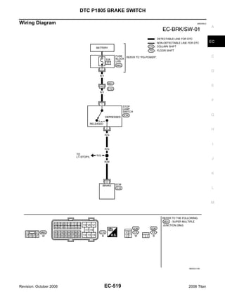
![DTC P1805 BRAKE SWITCH
Specification data are reference values and are measured between each terminal and ground.
CAUTION:
Do not use ECM ground terminals when measuring input/output voltage. Doing so may result in dam-
age to the ECM's transistor. Use a ground other than ECM terminals, such as the ground.
TER-
WIRE
MINAL ITEM CONDITION DATA (DC Voltage)
COLOR
NO.
[Ignition switch: OFF]
Approximately 0V
G Brake pedal: Fully released
101 R/W Stop lamp switch
[Ignition switch: OFF] BATTERY VOLTAGE
G Brake pedal: Slightly depressed (11 - 14V)
Diagnostic Procedure UBS00NL6
1. CHECK STOP LAMP SWITCH CIRCUIT
1. Turn ignition switch OFF.
2. Check the stop lamp when depressing and releasing the brake pedal.
Brake pedal Stop lamp
Fully released Not illuminated
Depressed Illuminated
OK or NG
OK >> GO TO 4.
NG >> GO TO 2.
2. CHECK STOP LAMP SWITCH POWER SUPPLY CIRCUIT
1. Disconnect stop lamp switch harness connector.
BBIA0373E
2. Check voltage between stop lamp switch terminal 1 and ground
with CONSULT-II or tester.
Voltage: Battery voltage
OK or NG
OK >> GO TO 4.
NG >> GO TO 3.
WBIA0545E
Revision: October 2006 EC-520 2006 Titan](https://image.slidesharecdn.com/ec-110402131317-phpapp02/85/Ec-520-320.jpg)

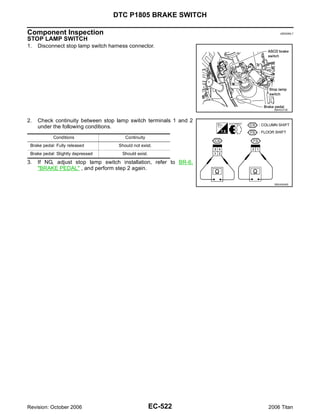


![DTC P2100, P2103 THROTTLE CONTROL MOTOR RELAY
Specification data are reference values and are measured between each terminal and ground.
Pulse signal is measured by CONSULT-II.
CAUTION:
Do not use ECM ground terminals when measuring input/output voltage. Doing so may result in dam-
age to the ECM's transistor. Use a ground other than ECM terminals, such as the ground.
TER-
WIRE
MINAL ITEM CONDITION DATA (DC Voltage)
COLOR
NO.
Throttle control motor relay BATTERY VOLTAGE
3 L [Ignition switch: ON]
power supply (11 - 14V)
0 - 14V
[Ignition switch: ON]
Throttle control motor G Engine: Stopped
4 L/W
(Close) G Selector lever: D
G Accelerator pedal: Fully released
PBIB1104E
0 - 14V
[Ignition switch: ON]
Throttle control motor G Engine: Stopped
5 L/B
(Open) G Selector lever: D
G Accelerator pedal: Fully depressed
PBIB1105E
BATTERY VOLTAGE
104 O Throttle control motor relay [Ignition switch: OFF]
(11 - 14V)
[Ignition switch: ON] 0 - 1.0V
: Average voltage for pulse signal (Actual pulse signal can be confirmed by oscilloscope.)
Diagnostic Procedure UBS00NLD
1. CHECK THROTTLE CONTROL MOTOR RELAY POWER SUPPLY CIRCUIT-I
1. Turn ignition switch OFF.
2. Check voltage between ECM terminal 104 and ground with
CONSULT-II or tester.
Voltage: Battery voltage
OK or NG
OK >> GO TO 4.
NG >> GO TO 2.
PBIB1171E
Revision: October 2006 EC-526 2006 Titan](https://image.slidesharecdn.com/ec-110402131317-phpapp02/85/Ec-526-320.jpg)


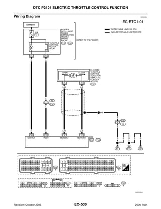
![DTC P2101 ELECTRIC THROTTLE CONTROL FUNCTION
Specification data are reference values and are measured between each terminal and ground.
Pulse signal is measured by CONSULT-II. A
CAUTION:
Do not use ECM ground terminals when measuring input/output voltage. Doing so may result in dam-
age to the ECM's transistor. Use a ground other than ECM terminals, such as the ground. EC
TER-
WIRE
MINAL ITEM CONDITION DATA (DC Voltage)
COLOR
NO.
C
Throttle control motor relay BATTERY VOLTAGE
3 L [Ignition switch: ON]
power supply (11 - 14V)
0 - 14V D
[Ignition switch: ON]
Throttle control motor G Engine: Stopped
4 L/W E
(Close) G Selector lever: D
G Accelerator pedal: Fully released
PBIB1104E F
0 - 14V
[Ignition switch: ON]
G
Throttle control motor G Engine: Stopped
5 L/B
(Open) G Selector lever: D
G Accelerator pedal: Fully depressed H
PBIB1105E
BATTERY VOLTAGE
104 O Throttle control motor relay [Ignition switch: OFF] I
(11 - 14V)
[Ignition switch: ON] 0 - 1.0V
: Average voltage for pulse signal (Actual pulse signal can be confirmed by oscilloscope.) J
Diagnostic Procedure UBS00NLI
1. CHECK GROUND CONNECTIONS K
1. Turn ignition switch OFF.
2. Loosen and retighten three ground screws on the body.
Refer to EC-156, "Ground Inspection" . L
M
BBIA0354E
OK or NG
OK >> GO TO 2.
NG >> Repair or replace ground connections.
Revision: October 2006 EC-531 2006 Titan](https://image.slidesharecdn.com/ec-110402131317-phpapp02/85/Ec-531-320.jpg)


![DTC P2101 ELECTRIC THROTTLE CONTROL FUNCTION
10. CHECK ELECTRIC THROTTLE CONTROL ACTUATOR VISUALLY
1. Remove the intake air duct.
2. Check if foreign matter is caught between the throttle valve and
the housing.
OK or NG
OK >> GO TO 11.
NG >> Remove the foreign matter and clean the electric throttle
control actuator inside.
BBIA0364E
11. CHECK THROTTLE CONTROL MOTOR
Refer to EC-534, "Component Inspection" .
OK or NG
OK >> GO TO 12.
NG >> GO TO 13.
12. CHECK INTERMITTENT INCIDENT
Refer to EC-150, "TROUBLE DIAGNOSIS FOR INTERMITTENT INCIDENT" .
OK or NG
OK >> GO TO 13.
NG >> Repair or replace harness or connectors.
13. REPLACE ELECTRIC THROTTLE CONTROL ACTUATOR
1. Replace the electric throttle control actuator.
2. Perform EC-83, "Throttle Valve Closed Position Learning" .
3. Perform EC-85, "Idle Air Volume Learning" .
>> INSPECTION END
Component Inspection UBS00NLJ
THROTTLE CONTROL MOTOR
1. Disconnect electric throttle control actuator harness connector.
2. Check resistance between terminals 5 and 6.
Resistance: Approximately 1 - 15 Ω [at 25 °C (77°F)]
3. If NG, replace electric throttle control actuator and go to next
step.
4. Perform EC-83, "Throttle Valve Closed Position Learning" .
5. Perform EC-85, "Idle Air Volume Learning" .
PBIB2066E
Removal and Installation UBS00NLK
ELECTRIC THROTTLE CONTROL ACTUATOR
Refer to EM-17, "INTAKE MANIFOLD" .
Revision: October 2006 EC-534 2006 Titan](https://image.slidesharecdn.com/ec-110402131317-phpapp02/85/Ec-534-320.jpg)

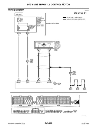
![DTC P2118 THROTTLE CONTROL MOTOR
Specification data are reference values and are measured between each terminal and ground.
Pulse signal is measured by CONSULT-II. A
CAUTION:
Do not use ECM ground terminals when measuring input/output voltage. Doing so may result in dam-
age to the ECM's transistor. Use a ground other than ECM terminals, such as the ground. EC
TER-
WIRE
MINAL ITEM CONDITION DATA (DC Voltage)
COLOR
NO.
C
Throttle control motor relay BATTERY VOLTAGE
3 L [Ignition switch: ON]
power supply (11 - 14V)
0 - 14V D
[Ignition switch: ON]
Throttle control motor G Engine: Stopped
4 L/W E
(Close) G Selector lever: D
G Accelerator pedal: Fully released
PBIB1104E F
0 - 14V
[Ignition switch: ON]
G
Throttle control motor G Engine: Stopped
5 L/B
(Open) G Selector lever: D
G Accelerator pedal: Fully depressed H
PBIB1105E
BATTERY VOLTAGE
104 O Throttle control motor relay [Ignition switch: OFF] I
(11 - 14V)
[Ignition switch: ON] 0 - 1.0V
: Average voltage for pulse signal (Actual pulse signal can be confirmed by oscilloscope.) J
Diagnostic Procedure UBS00NLP
1. CHECK GROUND CONNECTIONS K
1. Turn ignition switch OFF.
2. Loosen and retighten three ground screws on the body.
Refer to EC-156, "Ground Inspection" . L
M
BBIA0354E
OK or NG
OK >> GO TO 2.
NG >> Repair or replace ground connections.
Revision: October 2006 EC-537 2006 Titan](https://image.slidesharecdn.com/ec-110402131317-phpapp02/85/Ec-537-320.jpg)
![DTC P2118 THROTTLE CONTROL MOTOR
2. CHECK THROTTLE CONTROL MOTOR OUTPUT SIGNAL CIRCUIT FOR OPEN OR SHORT
1. Disconnect electric throttle control actuator harness connector.
2. Disconnect ECM harness connector.
3. Check harness continuity between the following terminals.
Refer to Wiring Diagram.
Electric throttle control
ECM terminal Continuity
actuator terminal
5 Should not exist
5
4 Should exist
5 Should exist BBIA0371E
6
4 Should not exist
4. Also check harness for short to ground and short to power.
OK or NG
OK >> GO TO 3.
NG >> Repair or replace.
3. CHECK THROTTLE CONTROL MOTOR
Refer to EC-538, "Component Inspection" .
OK or NG
OK >> GO TO 4.
NG >> GO TO 5.
4. CHECK INTERMITTENT INCIDENT
Refer to EC-150, "TROUBLE DIAGNOSIS FOR INTERMITTENT INCIDENT" .
OK or NG
OK >> GO TO 5.
NG >> Repair or replace harness or connectors.
5. REPLACE ELECTRIC THROTTLE CONTROL ACTUATOR
1. Replace the electric throttle control actuator.
2. Perform EC-83, "Throttle Valve Closed Position Learning" .
3. Perform EC-85, "Idle Air Volume Learning" .
>> INSPECTION END
Component Inspection UBS00NLQ
THROTTLE CONTROL MOTOR
1. Disconnect electric throttle control actuator harness connector.
2. Check resistance between terminals 5 and 6.
Resistance: Approximately 1 - 15 Ω [at 25 °C (77°F)]
3. If NG, replace electric throttle control actuator and go to next
step.
4. Perform EC-83, "Throttle Valve Closed Position Learning" .
5. Perform EC-85, "Idle Air Volume Learning" .
PBIB2066E
Revision: October 2006 EC-538 2006 Titan](https://image.slidesharecdn.com/ec-110402131317-phpapp02/85/Ec-538-320.jpg)


![DTC P2122, P2123 APP SENSOR
Specification data are reference values and are measured between each terminal and ground.
CAUTION: A
Do not use ECM ground terminals when measuring input/output voltage. Doing so may result in dam-
age to the ECM's transistor. Use a ground other than ECM terminals, such as the ground.
TER- EC
WIRE
MINAL ITEM CONDITION DATA (DC Voltage)
COLOR
NO.
[Engine is running] C
Sensor ground
82 B/R G Warm-up condition Approximately 0V
(APP sensor 1)
G Idle speed
[Engine is running] D
Sensor ground
83 G/W G Warm-up condition Approximately 0V
(APP sensor 2)
G Idle speed
Sensor power supply E
90 L [Ignition switch: ON] Approximately 5V
(APP sensor 1)
Sensor power supply
91 W/R [Ignition switch: ON] Approximately 5V
(APP sensor 2) F
[Ignition switch: ON]
G Engine: Stopped 0.25 - 0.50V
G Accelerator pedal: Fully released G
Accelerator pedal position
98 G/R
sensor 2 [Ignition switch: ON]
G Engine: Stopped 2.0 - 2.5V
H
G Accelerator pedal: Fully depressed
[Ignition switch: ON]
G Engine: Stopped 0.5 - 1.0V
I
Accelerator pedal position G Accelerator pedal: Fully released
106 BR/W
sensor 1 [Ignition switch: ON]
G Engine: Stopped 4.2 - 4.8V J
G Accelerator pedal: Fully depressed
Diagnostic Procedure UBS00NM1
K
1. CHECK GROUND CONNECTIONS
1. Turn ignition switch OFF.
L
2. Loosen and retighten three ground screws on the body.
Refer to EC-156, "Ground Inspection" .
M
BBIA0354E
OK or NG
OK >> GO TO 2.
NG >> Repair or replace ground connections.
Revision: October 2006 EC-545 2006 Titan](https://image.slidesharecdn.com/ec-110402131317-phpapp02/85/Ec-545-320.jpg)
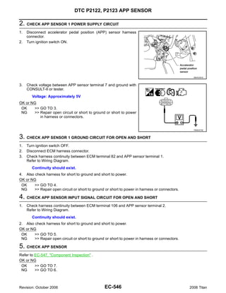
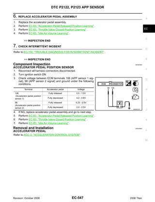


![DTC P2127, P2128 APP SENSOR
Specification data are reference values and are measured between each terminal and ground.
CAUTION: A
Do not use ECM ground terminals when measuring input/output voltage. Doing so may result in dam-
age to the ECM's transistor. Use a ground other than ECM terminals, such as the ground.
TER- EC
WIRE
MINAL ITEM CONDITION DATA (DC Voltage)
COLOR
NO.
Sensor power supply C
47 Y [Ignition switch: ON] Approximately 5V
(TP sensor)
[Engine is running]
Sensor ground
82 B/R G Warm-up condition Approximately 0V D
(APP sensor 1)
G Idle speed
[Engine is running]
Sensor ground
83 G/W G Warm-up condition Approximately 0V E
(APP sensor 2)
G Idle speed
Sensor power supply
90 L [Ignition switch: ON] Approximately 5V
(APP sensor 1) F
Sensor power supply
91 W/R [Ignition switch: ON] Approximately 5V
(APP sensor 2)
[Ignition switch: ON] G
G Engine: Stopped 0.25 - 0.50V
Accelerator pedal position G Accelerator pedal: Fully released
98 G/R H
sensor 2 [Ignition switch: ON]
G Engine: Stopped 2.0 - 2.5V
G Accelerator pedal: Fully depressed
I
[Ignition switch: ON]
G Engine: Stopped 0.5 - 1.0V
Accelerator pedal position G Accelerator pedal: Fully released
106 BR/W J
sensor 1 [Ignition switch: ON]
G Engine: Stopped 4.2 - 4.8V
G Accelerator pedal: Fully depressed K
Diagnostic Procedure UBS00NM9
1. CHECK GROUND CONNECTIONS L
1. Turn ignition switch OFF.
2. Loosen and retighten three ground screws on the body.
Refer to EC-156, "Ground Inspection" . M
BBIA0354E
OK or NG
OK >> GO TO 2.
NG >> Repair or replace ground connections.
Revision: October 2006 EC-551 2006 Titan](https://image.slidesharecdn.com/ec-110402131317-phpapp02/85/Ec-551-320.jpg)


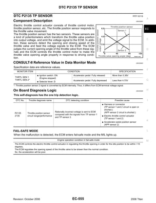


![DTC P2135 TP SENSOR
Specification data are reference values and are measured between each terminal and ground.
CAUTION:
Do not use ECM ground terminals when measuring input/output voltage. Doing so may result in dam-
age to the ECM's transistor. Use a ground other than ECM terminals, such as the ground.
TER-
WIRE
MINAL ITEM CONDITION DATA (DC Voltage)
COLOR
NO.
Sensor power supply
47 Y [Ignition switch: ON] Approximately 5V
(Throttle position sensor)
[Ignition switch: ON]
G Engine: Stopped
More than 0.36V
G Selector lever: D
G Accelerator pedal: Fully released
50 B Throttle position sensor 1
[Ignition switch: ON]
G Engine: Stopped
Less than 4.75V
G Selector lever: D
G Accelerator pedal: Fully depressed
[Engine is running]
Sensor ground
66 R G Warm-up condition Approximately 0V
(Throttle position sensor)
G Idle speed
[Ignition switch: ON]
G Engine: Stopped
Less than 4.75V
G Selector lever: D
G Accelerator pedal: Fully released
69 W Throttle position sensor 2
[Ignition switch: ON]
G Engine: Stopped
More than 0.36V
G Selector lever: D
G Accelerator pedal: Fully depressed
Sensor power supply
91 W/R [Ignition switch: ON] Approximately 5V
(APP sensor 2)
Diagnostic Procedure UBS00NMH
1. CHECK GROUND CONNECTIONS
1. Turn ignition switch OFF.
2. Loosen and retighten three ground screws on the body.
Refer to EC-156, "Ground Inspection" .
BBIA0354E
OK or NG
OK >> GO TO 2.
NG >> Repair or replace ground connections.
Revision: October 2006 EC-558 2006 Titan](https://image.slidesharecdn.com/ec-110402131317-phpapp02/85/Ec-558-320.jpg)


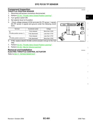


![DTC P2138 APP SENSOR
Specification data are reference values and are measured between each terminal and ground.
CAUTION: A
Do not use ECM ground terminals when measuring input/output voltage. Doing so may result in dam-
age to the ECM's transistor. Use a ground other than ECM terminals, such as the ground.
TER- EC
WIRE
MINAL ITEM CONDITION DATA (DC Voltage)
COLOR
NO.
Sensor power supply C
47 Y [Ignition switch: ON] Approximately 5V
(TP sensor)
[Engine is running]
Sensor ground
82 B/R G Warm-up condition Approximately 0V D
(APP sensor 1)
G Idle speed
[Engine is running]
Sensor ground
83 G/W G Warm-up condition Approximately 0V E
(APP sensor 2)
G Idle speed
Sensor power supply
90 L [Ignition switch: ON] Approximately 5V
(APP sensor 1) F
Sensor power supply
91 W/R [Ignition switch: ON] Approximately 5V
(APP sensor 2)
[Ignition switch: ON] G
G Engine: Stopped 0.25 - 0.50V
Accelerator pedal position G Accelerator pedal: Fully released
98 G/R H
sensor 2 [Ignition switch: ON]
G Engine: Stopped 2.0 - 2.5V
G Accelerator pedal: Fully depressed
I
[Ignition switch: ON]
G Engine: Stopped 0.5 - 1.0V
Accelerator pedal position G Accelerator pedal: Fully released
106 BR/W J
sensor 1 [Ignition switch: ON]
G Engine: Stopped 4.2 - 4.8V
G Accelerator pedal: Fully depressed K
Diagnostic Procedure UBS00NMP
1. CHECK GROUND CONNECTIONS L
1. Turn ignition switch OFF.
2. Loosen and retighten three ground screws on the body.
Refer to EC-156, "Ground Inspection" . M
BBIA0354E
OK or NG
OK >> GO TO 2.
NG >> Repair or replace ground connections.
Revision: October 2006 EC-565 2006 Titan](https://image.slidesharecdn.com/ec-110402131317-phpapp02/85/Ec-565-320.jpg)


![DTC P2A00, P2A03 A/F SENSOR 1
Specification data are reference values and are measured between each terminal and ground.
Pulse signal is measured by CONSULT-II. A
CAUTION:
Do not use ECM ground terminals when measuring input/output voltage. Doing so may result in dam-
age to the ECM's transistor. Use a ground other than ECM terminals, such as the ground. EC
TER-
WIRE
MINAL ITEM CONDITION DATA (DC Voltage)
COLOR
NO.
C
Approximately 5V
[Engine is running] D
A/F sensor 1 heater
2 O/B G Warm-up condition
(bank 1)
G Idle speed
E
PBIB1584E
16 BR/R Approximately 3.1V
[Engine is running] F
35 BR/G Approximately 2.6V
A/F sensor 1 (bank 1) G Warm-up condition
56 LG/B Approximately 2.3V
G Idle speed
75 P/B Approximately 2.3V
G
: Average voltage for pulse signal (Actual pulse signal can be confirmed by oscilloscope.)
H
I
J
K
L
M
Revision: October 2006 EC-573 2006 Titan](https://image.slidesharecdn.com/ec-110402131317-phpapp02/85/Ec-573-320.jpg)

![DTC P2A00, P2A03 A/F SENSOR 1
Specification data are reference values and are measured between each terminal and ground.
Pulse signal is measured by CONSULT-II. A
CAUTION:
Do not use ECM ground terminals when measuring input/output voltage. Doing so may result in dam-
age to the ECM's transistor. Use a ground other than ECM terminals, such as the ground. EC
TER-
WIRE
MINAL ITEM CONDITION DATA (DC Voltage)
COLOR
NO.
C
Approximately 5V
[Engine is running] D
A/F sensor 1 heater
24 BR/W G Warm-up condition
(bank 2)
G Idle speed
E
PBIB1584E
57 L/P Approximately 2.6V
[Engine is running] F
58 GR/G Approximately 2.3V
A/F sensor 1 (bank 2) G Warm-up condition
76 G/L Approximately 3.1V
G Idle speed
77 BR/B Approximately 2.3V
G
: Average voltage for pulse signal (Actual pulse signal can be confirmed by oscilloscope.)
Diagnostic Procedure UBS00NMX
H
1. CHECK GROUND CONNECTIONS
1. Turn ignition switch OFF.
I
2. Loosen and retighten two ground screws on the body.
Refer to EC-156, "Ground Inspection" .
J
K
L
BBIA0354E
M
OK or NG
OK >> GO TO 2.
NG >> Repair or replace ground connections.
Revision: October 2006 EC-575 2006 Titan](https://image.slidesharecdn.com/ec-110402131317-phpapp02/85/Ec-575-320.jpg)


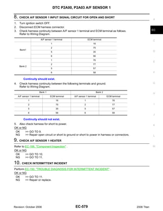


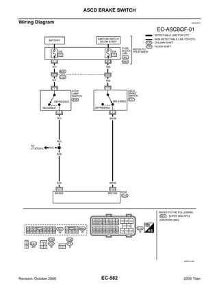
![ASCD BRAKE SWITCH
Specification data are reference values and are measured between each terminal and ground.
CAUTION: A
Do not use ECM ground terminals when measuring input/output voltage. Doing so may result in dam-
age to the ECM's transistor. Use a ground other than ECM terminals, such as the ground.
TER- EC
WIRE
MINAL ITEM CONDITION DATA (DC Voltage)
COLOR
NO.
[Ignition switch: OFF] C
Approximately 0V
G Brake pedal: Fully released
101 R/WL Stop lamp switch
[Ignition switch: OFF] BATTERY VOLTAGE
G Brake pedal: Slightly depressed (11 - 14V) D
[Ignition switch: ON] BATTERY VOLTAGE
G Brake pedal: Fully released (11 - 14V)
108 BR/W ASCD brake switch E
[Ignition switch: ON]
Approximately 0V
G Brake pedal: Slightly depressed
Diagnostic Procedure UBS00NN2 F
1. CHECK OVERALL FUNCTION-I
With CONSULT-II G
1. Turn ignition switch ON.
2. Select “BRAKE SW 1” in “DATA MONITOR” mode with CONSULT-II.
3. Check “BRAKE SW 1” indication under the following conditions. H
CONDITION INDICATION
Brake pedal: Slightly depressed OFF I
Brake pedal: Fully released ON
J
K
SEC011D
Without CONSULT-II
L
1. Turn ignition switch ON.
2. Check voltage between ECM terminal 108 and ground under the
following conditions.
M
CONDITION VOLTAGE
Brake pedal: Slightly depressed Approximately 0V
Brake pedal: Fully released Battery voltage
MBIB0061E
OK or NG
OK >> GO TO 2.
NG >> GO TO 3.
Revision: October 2006 EC-583 2006 Titan](https://image.slidesharecdn.com/ec-110402131317-phpapp02/85/Ec-583-320.jpg)


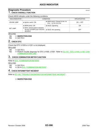


![FUEL INJECTOR
Specification data are reference values and are measured between each terminal and ground.
Pulse signal is measured by CONSULT-II.
CAUTION:
Do not use ECM ground terminals when measuring input/output voltage. Doing so may result in dam-
age to the ECM's transistor. Use a ground other than ECM terminals, such as the ground.
TER-
WIRE
MINAL ITEM CONDITION DATA (DC Voltage)
COLOR
NO.
BATTERY VOLTAGE
(11 - 14V)
[Engine is running]
G Warm-up condition
G Idle speed
21 O/L Fuel injector No. 5 NOTE:
22 BR Fuel injector No. 3 The pulse cycle changes depending on rpm at idle.
23 GR/W Fuel injector No. 1
40 Y/G Fuel injector No. 6 PBIB0042E
41 P Fuel injector No. 4 BATTERY VOLTAGE
42 L Fuel injector No. 2
(11 - 14V)
44 O Fuel injector No. 7
63 G Fuel injector No. 8 [Engine is running]
G Warm-up condition
G Engine speed: 2,000 rpm
PBIB0043E
: Average voltage for pulse signal (Actual pulse signal can be confirmed by oscilloscope.)
Diagnostic Procedure UBS00NNE
1. INSPECTION START
Turn ignition switch to START.
Is any cylinder ignited?
Yes or No
Yes >> GO TO 2.
No >> GO TO 3.
Revision: October 2006 EC-594 2006 Titan](https://image.slidesharecdn.com/ec-110402131317-phpapp02/85/Ec-594-320.jpg)
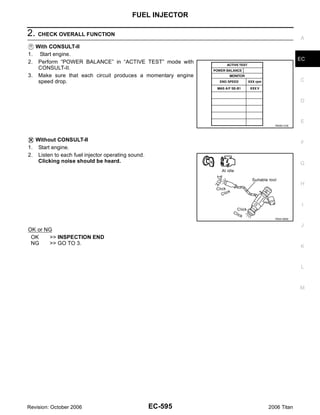

![FUEL INJECTOR
6. CHECK FUEL INJECTOR A
Refer to EC-594, "Diagnostic Procedure" .
OK or NG
OK >> GO TO 7. EC
NG >> Replace fuel injector.
7. CHECK INTERMITTENT INCIDENT C
Refer to EC-150, "TROUBLE DIAGNOSIS FOR INTERMITTENT INCIDENT" .
D
>> INSPECTION END
Component Inspection UBS00NNF
FUEL INJECTOR E
1. Disconnect fuel injector harness connector.
2. Check resistance between terminals as shown in the figure.
Resistance: 11.1 - 14.5Ω [at 10 - 60°C (50 - 140°F)] F
G
H
PBIB1727E
I
Removal and Installation UBS00NNG
FUEL INJECTOR
Refer to EM-31, "FUEL INJECTOR AND FUEL TUBE" . J
K
L
M
Revision: October 2006 EC-597 2006 Titan](https://image.slidesharecdn.com/ec-110402131317-phpapp02/85/Ec-597-320.jpg)


![FUEL PUMP
Specification data are reference values and are measured between each terminal and ground.
CAUTION:
Do not use ECM ground terminals when measuring input/output voltage. Doing so may result in dam-
age to the ECM's transistor. Use a ground other than ECM terminals, such as the ground.
TER-
WIRE
MINAL ITEM CONDITION DATA (DC Voltage)
COLOR
NO.
[Ignition switch: ON]
G For 1 second after turning ignition switch ON 0 - 1.5V
[Engine is running]
113 GR Fuel pump relay
[Ignition switch: ON]
BATTERY VOLTAGE
G More than 1 second after turning ignition (11 - 14V)
switch ON.
Revision: October 2006 EC-600 2006 Titan](https://image.slidesharecdn.com/ec-110402131317-phpapp02/85/Ec-600-320.jpg)

![FUEL PUMP
CAUTION:
Do not use ECM ground terminals when measuring input/output voltage. Doing so may result in dam-
age to the ECM's transistor. Use a ground other than ECM terminals, such as the ground.
TER-
WIRE
MINAL ITEM CONDITION DATA (DC Voltage)
COLOR
NO.
[Ignition switch: ON]
G More than a few seconds after turning igni- Approximately 0V
tion switch ON
[Ignition switch: ON]
Fuel pump control module
38 L G For a few seconds after turning ignition
(FPCM) check
switch ON
4 - 6V
[Engine is running]
G Warm-up condition
G Idle speed
[When cranking engine] 0 - 0.5V
Fuel pump control module [Engine is running]
39 L/Y
(FPCM) G Warm-up condition 8 - 12V
G Idle speed
[Ignition switch: ON]
G For 1 second after turning ignition switch ON 0 - 1.5V
[Engine is running]
113 GR Fuel pump relay
[Ignition switch: ON]
BATTERY VOLTAGE
G More than 1 second after turning ignition (11 - 14V)
switch ON.
Diagnostic Procedure UBS00NNK
EXCEPT FLEXIBLE FUEL VEHICLE
1. CHECK OVERALL FUNCTION
1. Turn ignition switch ON.
2. Pinch fuel feed hose with two fingers.
Fuel pressure pulsation should be felt on the fuel feed
hose for 1 second after ignition switch is turned ON.
OK or NG
OK >> INSPECTION END
NG >> GO TO 2.
BBIA0357E
Revision: October 2006 EC-602 2006 Titan](https://image.slidesharecdn.com/ec-110402131317-phpapp02/85/Ec-602-320.jpg)


![FUEL PUMP
13. CHECK FUEL PUMP A
Refer to EC-609, "Component Inspection" .
OK or NG
OK >> GO TO 14. EC
NG >> Replace “fuel level sensor unit and fuel pump”.
14. CHECK INTERMITTENT INCIDENT C
Refer to EC-150, "TROUBLE DIAGNOSIS FOR INTERMITTENT INCIDENT" .
D
OK or NG
OK >> Replace IPDM E/R.
NG >> Repair or replace harness or connectors.
E
Component Inspection UBS00NNL
FUEL PUMP
1. Disconnect “fuel level sensor unit and fuel pump” harness connector. F
2. Check resistance between fuel level sensor unit and fuel pump
terminals 1 and 3.
Resistance: 0.2 - 5.0Ω [at 25°C (77°F)] G
H
I
SEC918C
DROPPING RESISTOR
J
1. Turn ignition switch OFF.
2. Disconnect dropping resistor harness connector.
3. Check resistance between dropping resistor terminals as 1 and
K
2.
Resistance Above 1 MΩ at 25°C (77°F)
L
M
PBIB0131E
CONDENSER-2
1. Turn ignition switch OFF.
2. Disconnect condenser-2 harness connector.
Revision: October 2006 EC-609 2006 Titan](https://image.slidesharecdn.com/ec-110402131317-phpapp02/85/Ec-609-320.jpg)


![IGNITION SIGNAL
Specification data are reference values and are measured between each terminal and ground.
CAUTION: A
Do not use ECM ground terminals when measuring input/output voltage. Doing so may result in dam-
age to the ECM's transistor. Use a ground other than ECM terminals, such as the ground.
TER- EC
WIRE
MINAL ITEM CONDITION DATA (DC Voltage)
COLOR
NO.
[Engine is running] C
[Ignition switch: OFF]
0 - 1.5V
G For a few seconds after turning ignition
ECM relay switch OFF
111 W/B
(Self shut-off) D
[Ignition switch: OFF]
BATTERY VOLTAGE
G More than a few seconds after turning igni- (11 - 14V)
tion switch OFF
E
119 BR BATTERY VOLTAGE
Power supply for ECM [Ignition switch: ON]
120 BR (11 - 14V)
F
G
H
I
J
K
L
M
Revision: October 2006 EC-613 2006 Titan](https://image.slidesharecdn.com/ec-110402131317-phpapp02/85/Ec-613-320.jpg)

![IGNITION SIGNAL
Specification data are reference values and are measured between each terminal and ground.
Pulse signal is measured by CONSULT-II. A
CAUTION:
Do not use ECM ground terminals when measuring input/output voltage. Doing so may result in dam-
age to the ECM's transistor. Use a ground other than ECM terminals, such as the ground. EC
TER-
WIRE
MINAL ITEM CONDITION DATA (DC Voltage)
COLOR
NO.
C
0 - 0.2V
[Engine is running]
G Warm-up condition
D
G Idle speed
NOTE:
The pulse cycle changes depending on rpm at
46 L/R Ignition signal No. 7 idle. E
PBIB0044E
60 GR/R Ignition signal No. 5
61 O/W Ignition signal No. 3
0.1 - 0.4V
62 Y/R Ignition signal No. 1
F
[Engine is running]
G Warm-up condition
G Engine speed: 2,000 rpm. G
PBIB0045E
H
: Average voltage for pulse signal (Actual pulse signal can be confirmed by oscilloscope.)
I
J
K
L
M
Revision: October 2006 EC-615 2006 Titan](https://image.slidesharecdn.com/ec-110402131317-phpapp02/85/Ec-615-320.jpg)

![IGNITION SIGNAL
Specification data are reference values and are measured between each terminal and ground.
Pulse signal is measured by CONSULT-II. A
CAUTION:
Do not use ECM ground terminals when measuring input/output voltage. Doing so may result in dam-
age to the ECM's transistor. Use a ground other than ECM terminals, such as the ground. EC
TER-
WIRE
MINAL ITEM CONDITION DATA (DC Voltage)
COLOR
NO.
C
0 - 0.2V
[Engine is running]
G Warm-up condition
D
G Idle speed
NOTE:
The pulse cycle changes depending on rpm at
65 G/R Ignition signal No. 8 idle. E
PBIB0044E
79 V/W Ignition signal No. 6
80 W/R Ignition signal No. 4
0.1 - 0.4V
81 W/G Ignition signal No. 2
F
[Engine is running]
G Warm-up condition
G Engine speed: 2,000 rpm. G
PBIB0045E
H
: Average voltage for pulse signal (Actual pulse signal can be confirmed by oscilloscope.)
Diagnostic Procedure UBS00NNP
I
1. CHECK ENGINE START
Turn ignition switch OFF, and restart engine.
Is engine running? J
Yes or No
Yes (With CONSULT-II)>>GO TO 2.
Yes (Without CONSULT-II)>>GO TO 3. K
No >> GO TO 4.
2. CHECK OVERALL FUNCTION L
With CONSULT-II
1. Perform “POWER BALANCE” in “ACTIVE TEST” mode with
CONSULT-II. M
2. Make sure that each circuit produces a momentary engine
speed drop.
OK or NG
OK >> INSPECTION END
NG >> GO TO 10.
PBIB0133E
Revision: October 2006 EC-617 2006 Titan](https://image.slidesharecdn.com/ec-110402131317-phpapp02/85/Ec-617-320.jpg)


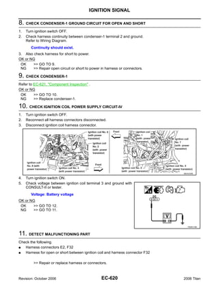
![IGNITION SIGNAL
12. CHECK IGNITION COIL GROUND CIRCUIT FOR OPEN AND SHORT A
1. Turn ignition switch OFF.
2. Check harness continuity between ignition coil terminal 2 and ground.
Refer to Wiring Diagram. EC
Continuity should exist.
3. Also check harness for short to power. C
OK or NG
OK >> GO TO 13.
NG >> Repair open circuit or short to power in harness or connectors. D
13. CHECK IGNITION COIL OUTPUT SIGNAL CIRCUIT FOR OPEN AND SHORT
1. Disconnect ECM harness connector. E
2. Check harness continuity between ECM terminals 46, 60, 61, 62, 65, 79, 80, 81 and ignition coil terminal
1.
Refer to Wiring Diagram. F
Continuity should exist.
3. Also check harness for short to ground and short to power. G
OK or NG
OK >> GO TO 14.
NG >> Repair open circuit or short to ground or short to power in harness or connectors. H
14. CHECK IGNITION COIL WITH POWER TRANSISTOR
Refer to EC-621, "Component Inspection" . I
OK or NG
OK >> GO TO 15.
J
NG >> Replace ignition coil with power transistor.
15. CHECK INTERMITTENT INCIDENT
K
Refer to EC-150, "TROUBLE DIAGNOSIS FOR INTERMITTENT INCIDENT" .
>> INSPECTION END L
Component Inspection UBS00NNQ
IGNITION COIL WITH POWER TRANSISTOR
M
CAUTION:
Do the following procedure in the place where ventilation is good without the combustible.
1. Turn ignition switch OFF.
2. Disconnect ignition coil harness connector.
3. Check resistance between ignition coil terminals as follows.
Terminal No. (Polarity) Resistance Ω [at 25°C (77°F)]
1 and 2 Except 0 or ∞
1 and 3
Except 0
2 and 3
4. If NG, replace ignition coil with power transistor.
If OK, go to next step.
5. Turn ignition switch OFF.
6. Reconnect all harness connectors disconnected. PBIB0847E
Revision: October 2006 EC-621 2006 Titan](https://image.slidesharecdn.com/ec-110402131317-phpapp02/85/Ec-621-320.jpg)

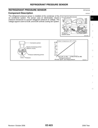

![REFRIGERANT PRESSURE SENSOR
Specification data are reference values and are measured between each terminal and ground.
CAUTION: A
Do not use ECM ground terminals when measuring input/output voltage. Doing so may result in dam-
age to the ECM's transistor. Use a ground other than ECM terminals, such as the ground.
TER- EC
WIRE
MINAL ITEM CONDITION DATA (DC Voltage)
COLOR
NO.
Sensor power supply C
49 R/Y (Refrigerant pressure sen- [Ignition switch: ON] Approximately 5V
sor)
[Engine is running]
D
67 B Sensor ground G Warm-up condition Approximately 0V
G Idle speed
[Engine is running] E
G Warm-up condition
70 B/W Refrigerant pressure sensor 1.0 - 4.0V
G Both A/C switch and blower switch: ON
(Compressor: Operates.)
F
Diagnostic Procedure UBS00NNU
1. CHECK REFRIGERANT PRESSURE SENSOR OVERALL FUNCTION G
1. Start engine and warm it up to normal operating temperature.
2. Turn A/C switch and blower switch ON.
3. Check voltage between ECM terminal 70 and ground with CON- H
SULT-II or tester.
Voltage: 1.0 - 4.0V I
OK or NG
OK >> INSPECTION END
NG >> GO TO 2. J
K
PBIB1188E
2. CHECK GROUND CONNECTIONS
L
1. Turn A/C switch and blower switch OFF.
2. Turn ignition switch OFF.
3. Loosen and retighten three ground screws on the body. M
Refer to EC-156, "Ground Inspection" .
BBIA0354E
OK or NG
OK >> GO TO 3.
NG >> Repair or replace ground connections.
Revision: October 2006 EC-625 2006 Titan](https://image.slidesharecdn.com/ec-110402131317-phpapp02/85/Ec-625-320.jpg)
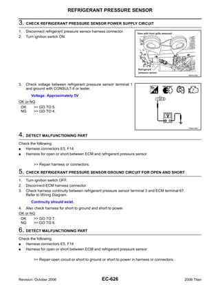

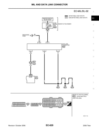
![SERVICE DATA AND SPECIFICATIONS (SDS)
SERVICE DATA AND SPECIFICATIONS (SDS) PFP:00030
Fuel Pressure UBS00NNX
Fuel pressure at idling kPa (kg/cm2 , psi) Approximately 350 (3.57, 51)
Idle Speed and Ignition Timing UBS00NNY
Target idle speed No-load* (in P or N position) 650±50 rpm
Air conditioner: ON In P or N position 700 rpm or more
Ignition timing In P or N position 15° ± 5° BTDC
*: Under the following conditions:
G Air conditioner switch: OFF
G Electric load: OFF (Lights and heater fan)
G Steering wheel: Kept in straight-ahead position
Calculated Load Value UBS00NNZ
Condition Calculated load value % (Using CONSULT-II or GST)
At idle 14.0 - 33.0
At 2,500 rpm 12.0 - 25.0
Mass Air Flow Sensor UBS00NO0
Supply voltage Battery voltage (11 - 14V)
Output voltage at idle 1.0 - 1.3V*
3.0 - 9.0 g·m/sec at idle*
Mass air flow (Using CONSULT-II or GST)
9.0 - 28.0 g·m/sec at 2,500 rpm*
*: Engine is warmed up to normal operating temperature and running under no load.
Intake Air Temperature Sensor UBS00NO1
Temperature °C (°F) Resistance kΩ
25 (77) 1.800 - 2.200
Engine Coolant Temperature Sensor UBS00NO2
Temperature °C (°F) Resistance kΩ
20 (68) 2.1 - 2.9
50 (122) 0.68 - 1.00
90 (194) 0.236 - 0.260
A/F Sensor 1 Heater UBS00NO3
Resistance [at 25°C (77°F)] 2.3 - 4.3Ω
Heated Oxygen sensor 2 Heater UBS00NO4
Resistance [at 25°C (77°F)] 5.0 - 7.0Ω
Crankshaft Position Sensor (POS) UBS00NO5
Refer to EC-352, "Component Inspection" .
Camshaft Position Sensor (PHASE) UBS00NO6
Refer to EC-359, "Component Inspection" .
Throttle Control Motor UBS00NO7
Resistance [at 25°C (77°F)] Approximately 1 - 15Ω
Revision: October 2006 EC-630 2006 Titan](https://image.slidesharecdn.com/ec-110402131317-phpapp02/85/Ec-630-320.jpg)
![SERVICE DATA AND SPECIFICATIONS (SDS)
Fuel Injector UBS00NO8
A
Resistance [at 10 - 60°C (50 - 140°F)] 11.1 - 14.5Ω
Fuel Pump UBS00NO9
EC
Resistance [at 25°C (77°F)] 0.2 - 5.0Ω
C
D
E
F
G
H
I
J
K
L
M
Revision: October 2006 EC-631 2006 Titan](https://image.slidesharecdn.com/ec-110402131317-phpapp02/85/Ec-631-320.jpg)


