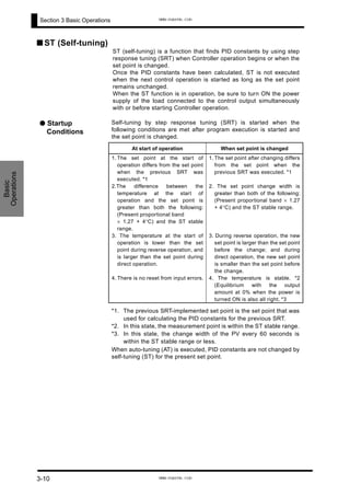
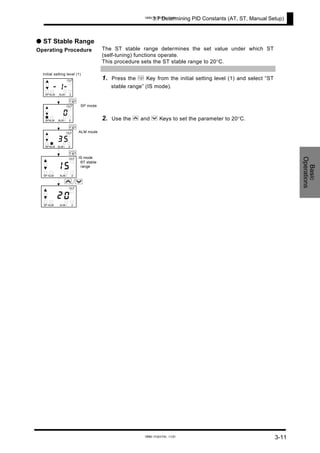
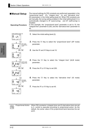
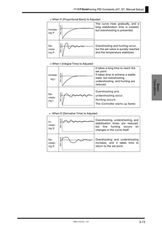
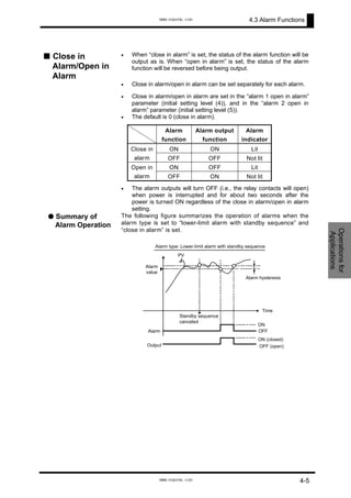
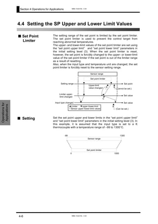
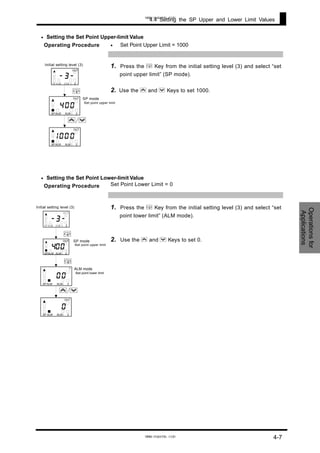
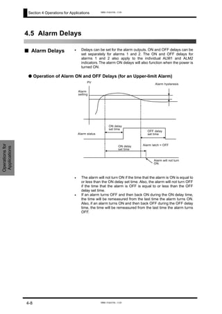
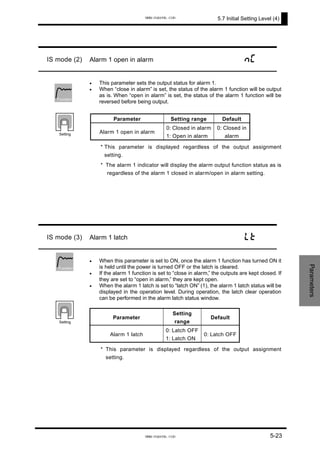
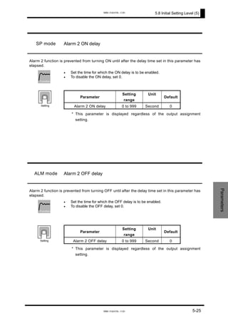
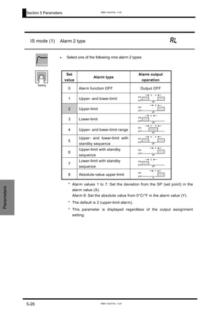
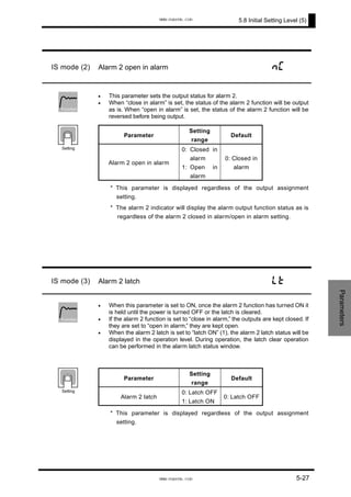
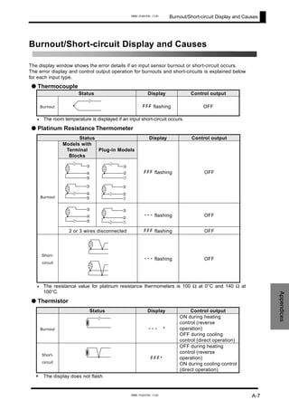
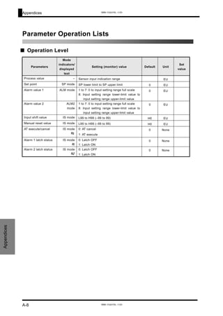
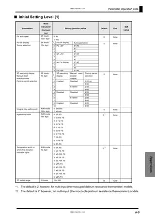
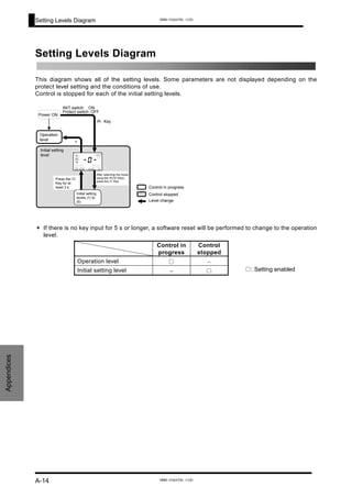
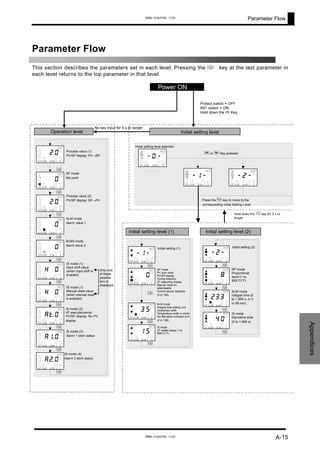
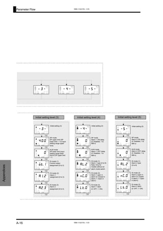
Download as PDF, PPTX
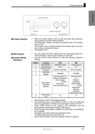
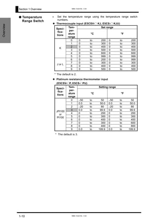
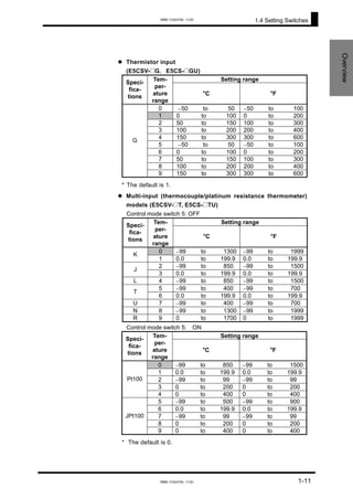
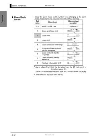
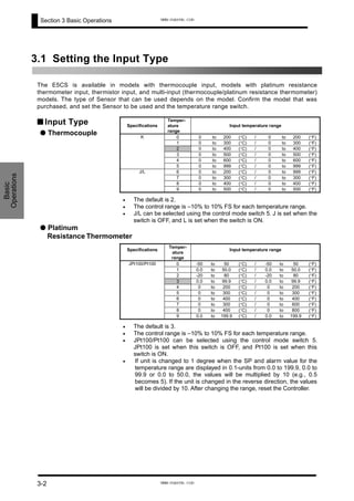
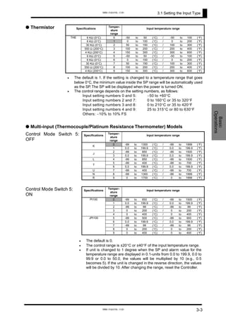

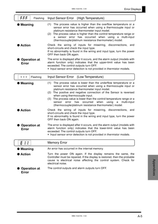
![Appendices
Appendices
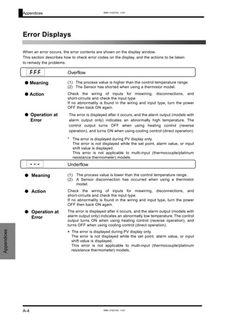
Display Range Exceeded
● Meaning This does not indicate an error. It is displayed if the process value
exceeds the display range when the control range is larger than the
display range.
•
•
When less than −99 : [[[
When more than 1999 : ]]]
● Operation Control continues, allowing normal operation. This display is shown
only during PV display.
[[[
]]]
A-6
www.eusens.com
www.eusens.com](https://image.slidesharecdn.com/e5csvmanual-160830144307/85/E5CSV-Manual-95-320.jpg)

The document is a user manual for OMRON's E5CSV and E5CS-U Digital Temperature Controllers. It provides an introduction to the controllers' main functions including various input types, temperature ranges, display, tuning functions, and IP66 waterproof rating. The manual also contains sections on warranty and liability limitations, application considerations, and safety precautions to ensure proper use of the controllers.


![NB Designer Manual Operation [unlockplc.com]](https://cdn.slidesharecdn.com/ss_thumbnails/nbdesignermanualoperationunlockplc-150515045539-lva1-app6891-thumbnail.jpg?width=640&height=640&fit=bounds)


