Download to read offline
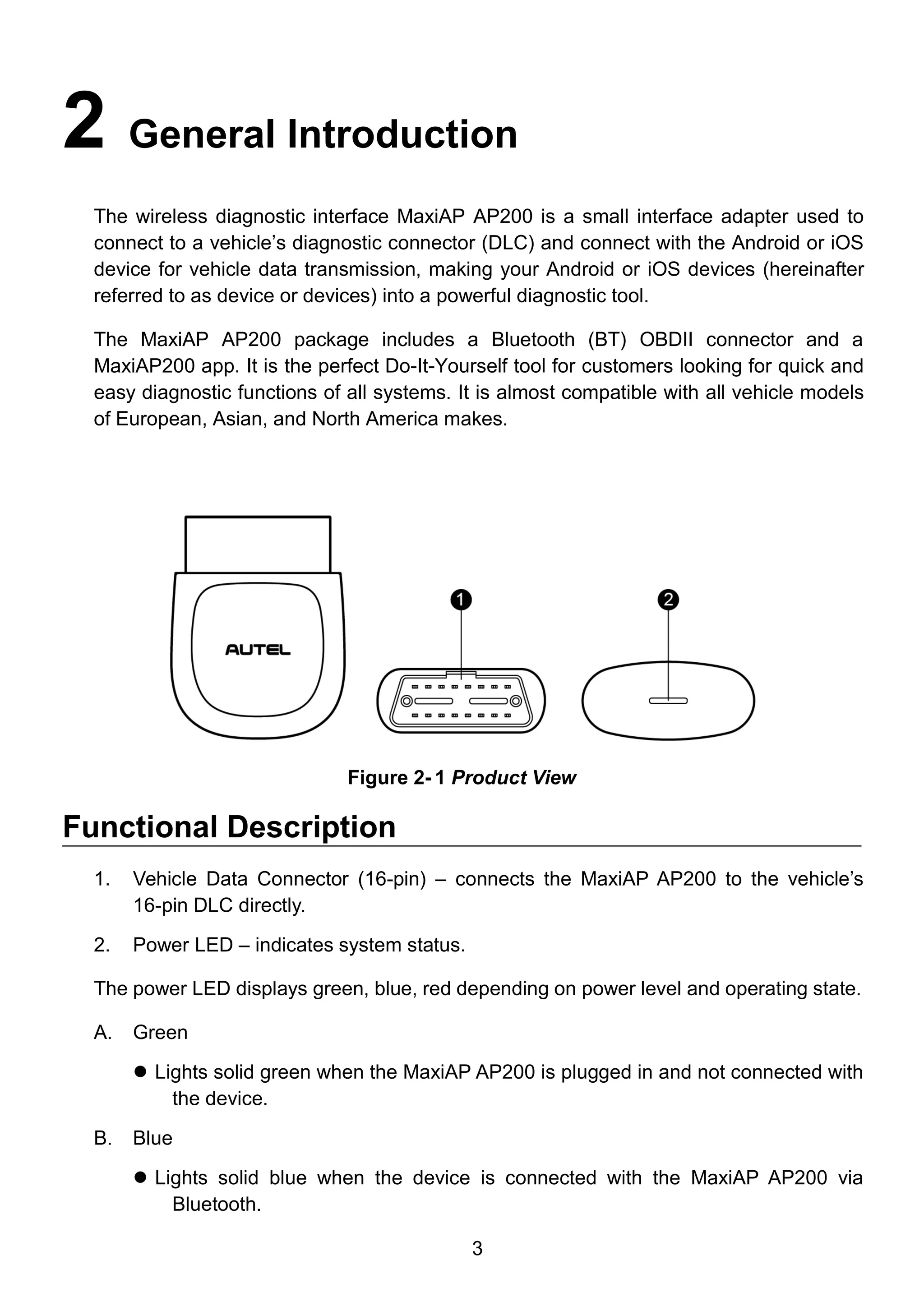
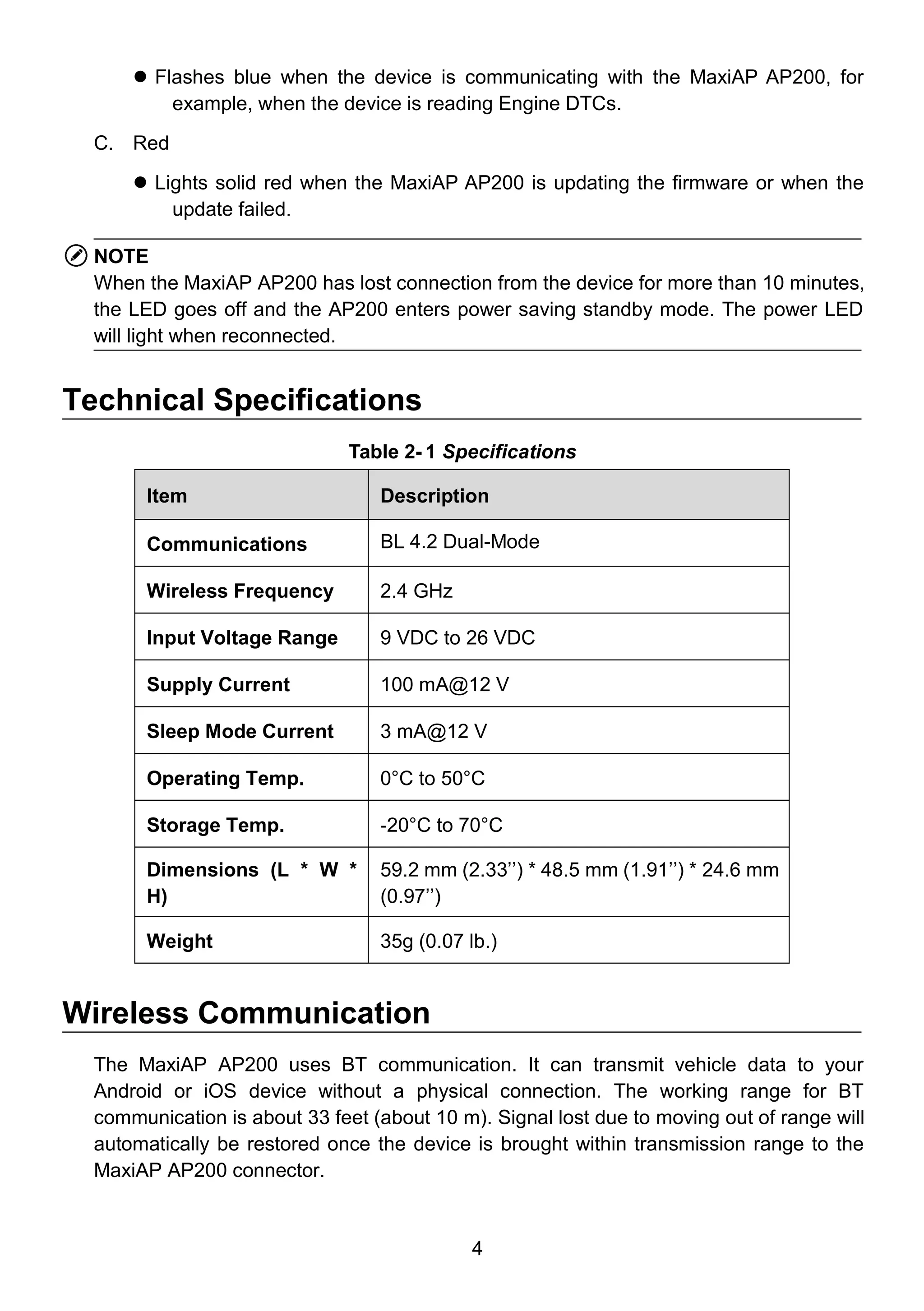

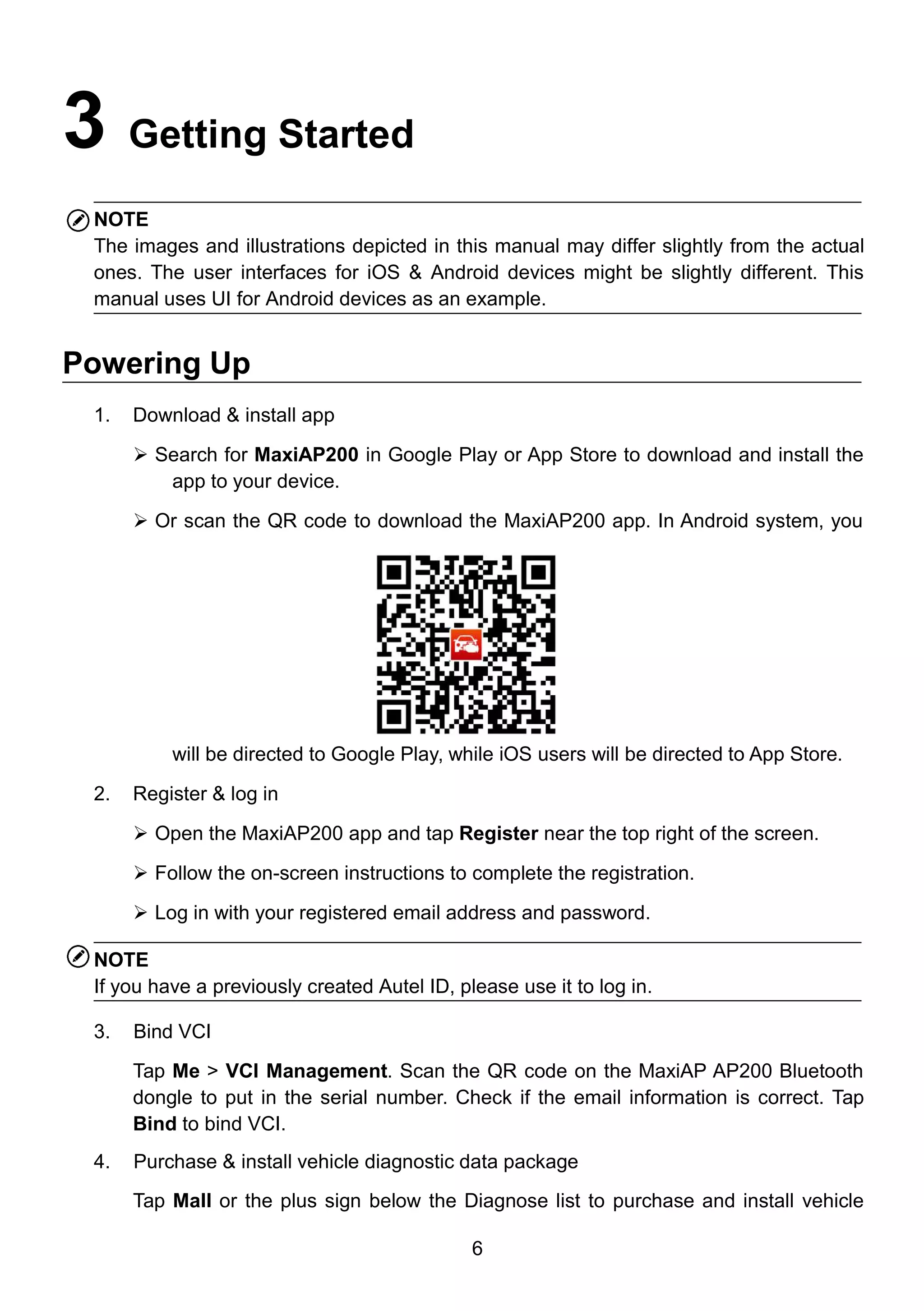
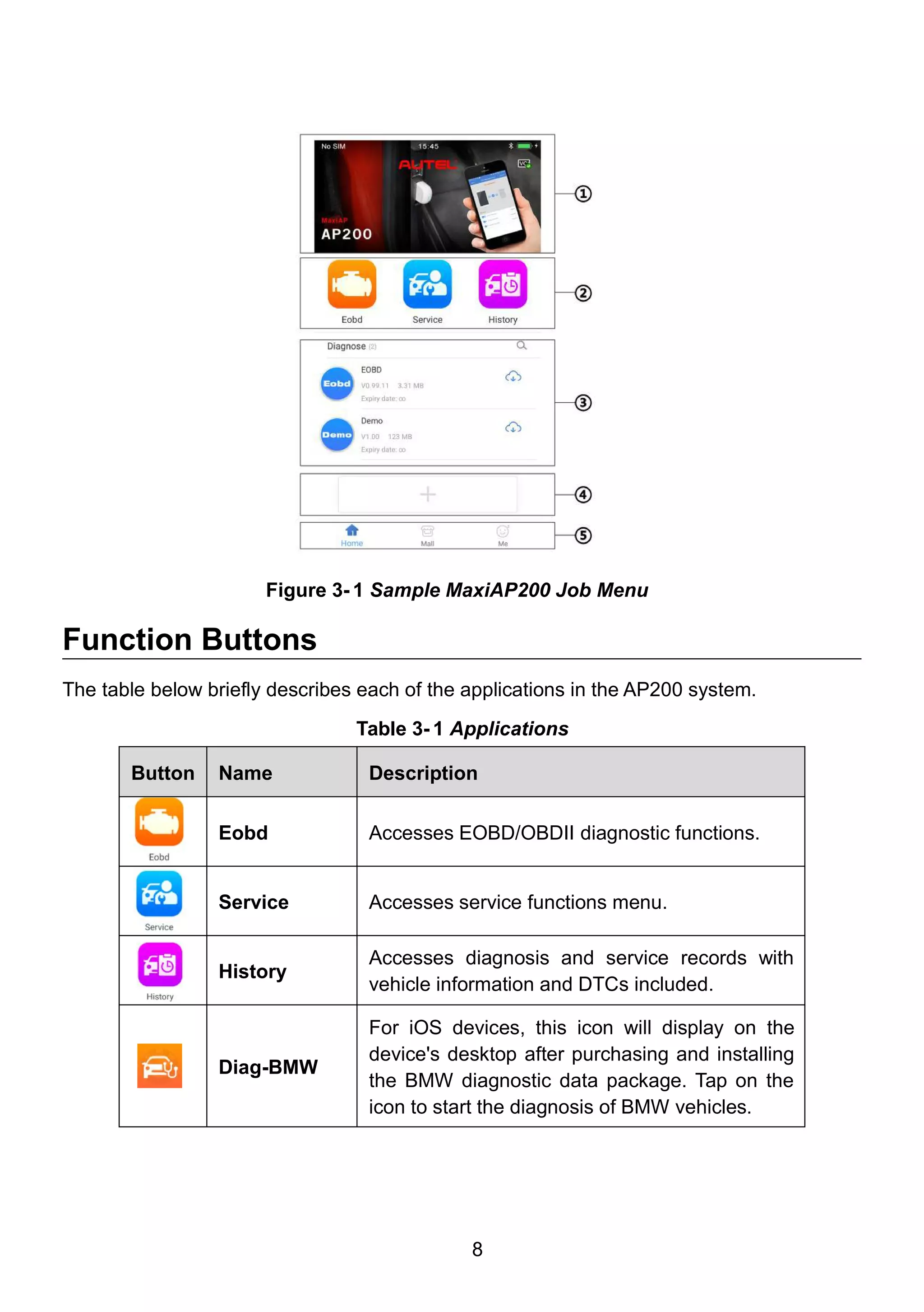


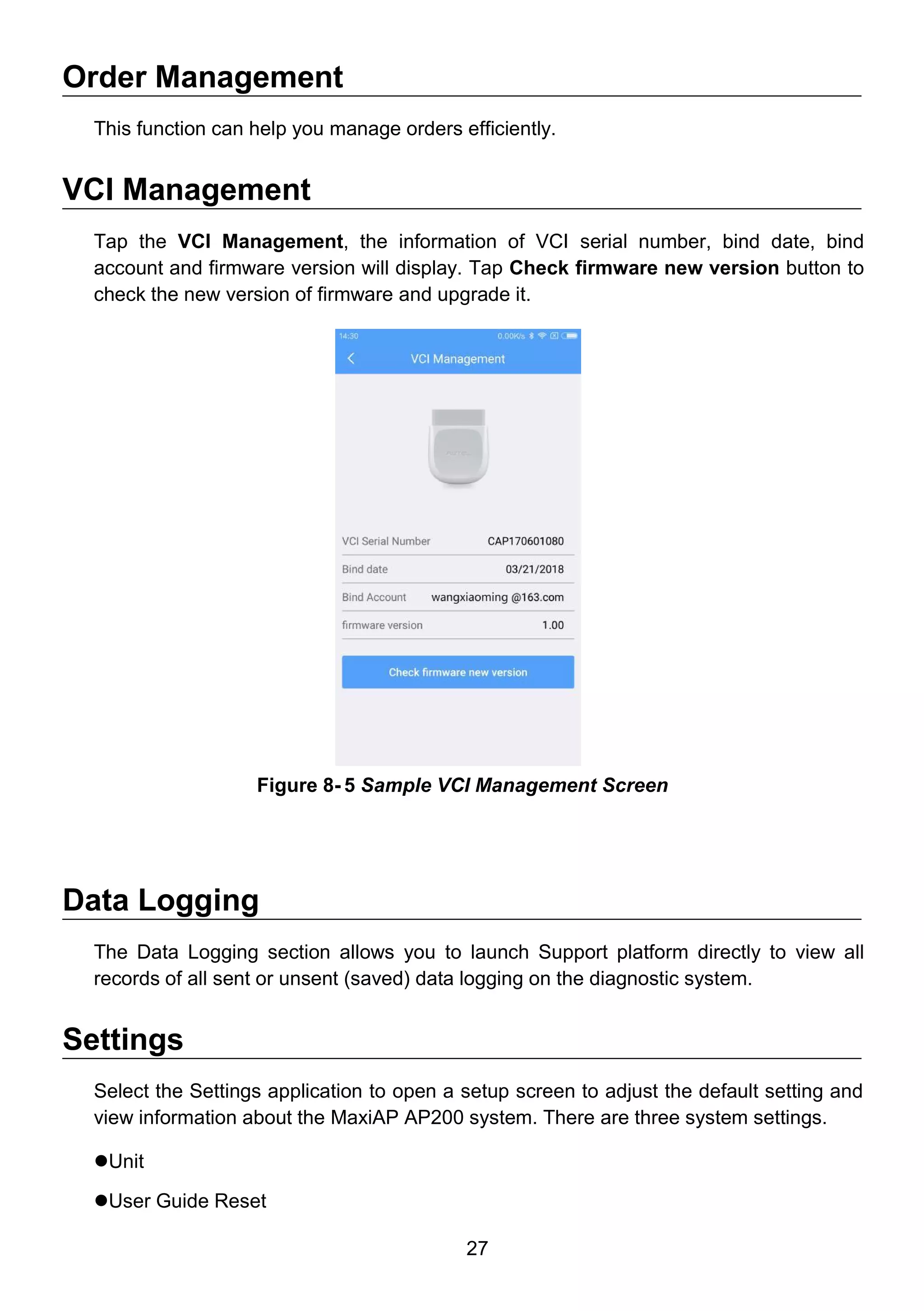
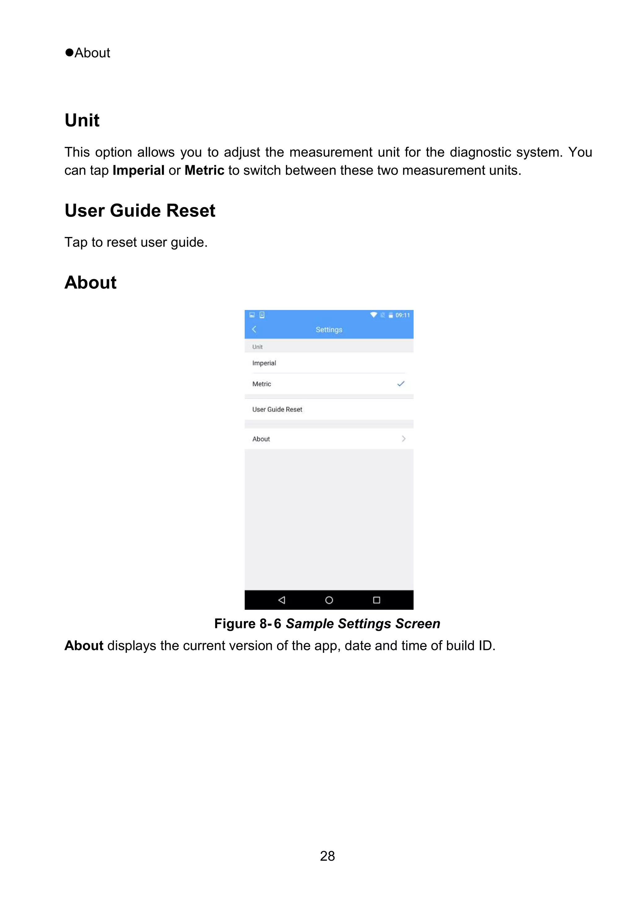
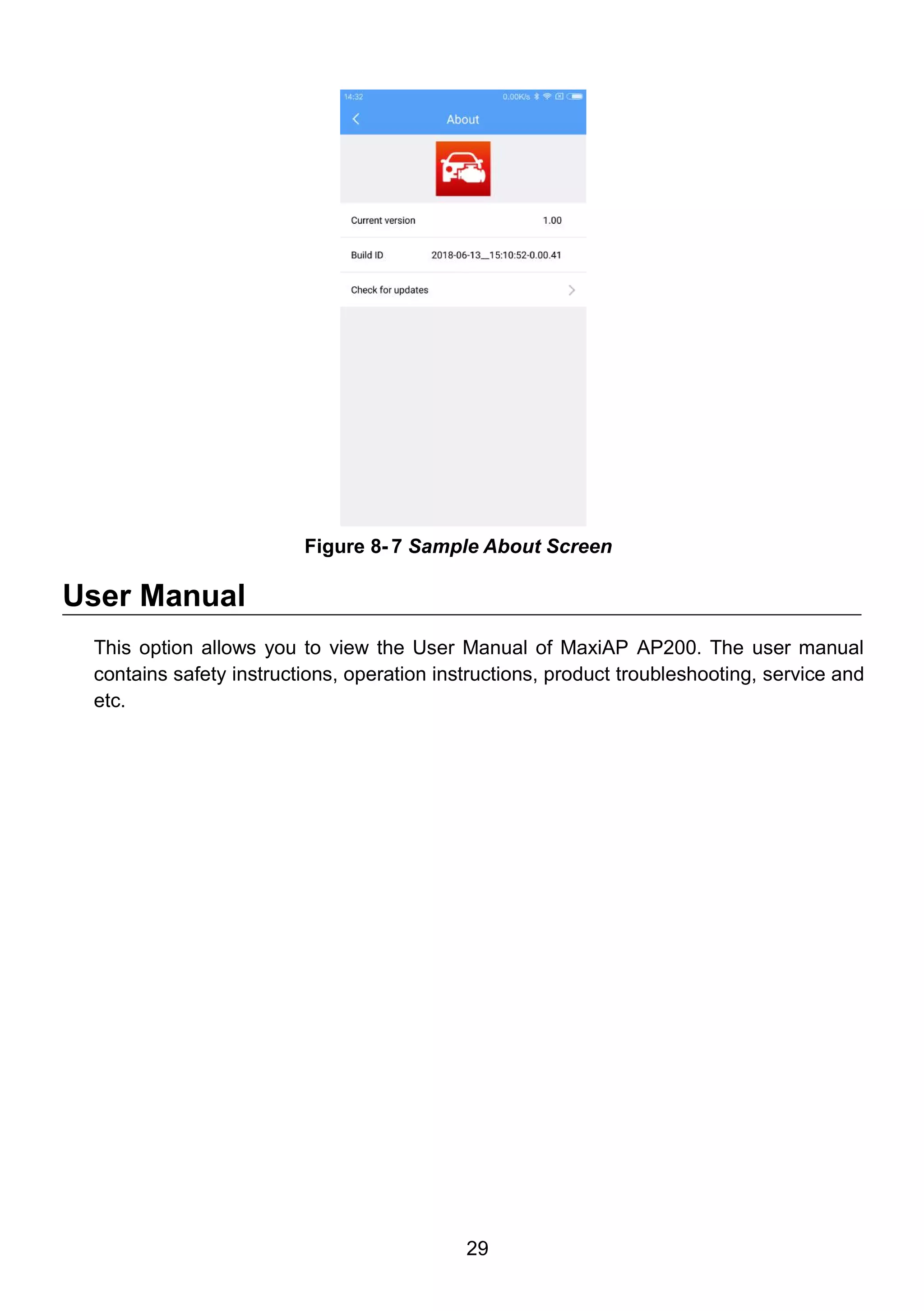


The document contains the user manual for the maxiap ap200, a Bluetooth OBDII diagnostic tool designed to connect vehicles' diagnostic connectors to Android or iOS devices. It provides safety instructions, usage guidelines, and technical specifications, highlighting the importance of reading the manual before operating the device for safe and effective diagnostics of vehicles. Additionally, it outlines how to install the application, connect the tool, and access various diagnostic functions.


![Mazda Dashboard Warning Lights: Symbols and Meanings [FULL LIST]](https://cdn.slidesharecdn.com/ss_thumbnails/mazda-warning-lights-221021085358-dcf733ba-thumbnail.jpg?width=640&height=640&fit=bounds)
![Mini Cooper Dashboard Warning Lights: Symbols and Meanings [FULL LIST]](https://cdn.slidesharecdn.com/ss_thumbnails/mini-cooper-warning-lights-221021084944-27b65ebd-thumbnail.jpg?width=640&height=640&fit=bounds)


![Toyota Dashboard Warning Lights [FULL]](https://cdn.slidesharecdn.com/ss_thumbnails/toyota-warning-lights-211126044903-thumbnail.jpg?width=640&height=640&fit=bounds)


