The CMO Survey - Highlights and Insights Report - Spring 2024
Download
1. Shackles
Applications
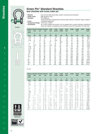
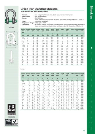
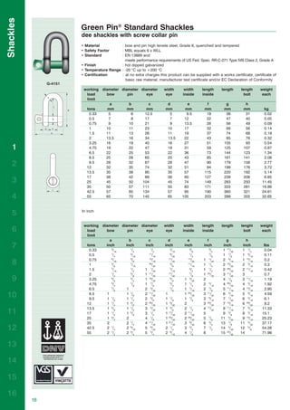
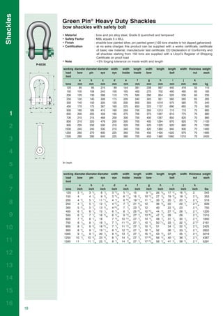
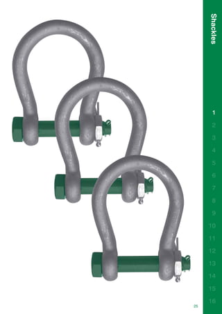
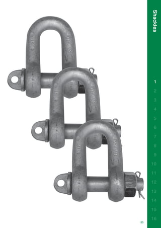
Shackles are used in lifting and static systems as removable links to connect (steel) wire rope, chain and other
fittings. Screw pin shackles are used mainly for non-permanent applications. Safety bolt shackles are used for
long-term or permanent applications or where the load may slide on the pin causing rotation of the pin.
Chain or dee shackles are mainly used on one-leg systems whereas anchor or bow shackles are mainly used
on multi-leg systems.
Range
Van Beest offers a wide range of bow and dee shackles, depending on the application on which the shackle
is going to be used; the range stretches from Working Load Limit (WLL) 0.33 tons to 1500 tons. Therefore, our
customers have a very extensive range to choose the shackle exactly suitable for the application. Most of the
shackles are directly available from stock. Furthermore, shackles can be supplied to many standards such as the
US Federal Specification RR-C-271, EN 13889, British Standard 3032, DIN 82101, DIN 82016 etc.
Polar shackles are for use in extreme climatic conditions with material properties guaranteed up to temperatures
of -40oC, and furthermore we offer a wide range of general commercial shackles, which are not suitable for lifting
but merely for fixing purposes.
Design
1
All Van Beest shackles have a specific design for a specific application. Examples are the “Super” shackles which
are made out of grade 8 steel enabling the dimensions of the shackles to be minimized for use in limited space
2 conditions, without loss of functionality or Working Load Limit.
Or sling shackles for use with large slings, to provide a better radius to the sling being used. Another example
of functional design is the use of shackles where the pin has a square sunken hole so as not to obstruct the use
of fishing nets. These are all examples of a highly functional design, to optimize the use of the Van Beest shackles
3 in daily use.
Furthermore, shackles used for lifting applications are stamped with the following marks, to specify the quality
4 and safety of use of the shackles:
- Working Load Limit ■ i.e. WLL 25 T
5 -
-
manufacturer’s identification symbol
traceability code
■
■
i.e. Bs, indicating Van Beest
i.e. H pertaining to a particular batch
- steel grade ■ i.e. 4, 6, 8
- CE conformity code ■ i.e. CE, Conformité Européen indicating that the product is suitable
6 for lifting purposes.
Van Beest Green Pin® shackles meet all relevant requirements of the Machinery Directive 98/37/EC and all latest
7 amendments.
8 Finish
Shackles supplied by Van Beest can be either hot dipped galvanized, electro-galvanized, painted or self colou-
9 red, depending on the type of shackle and its application.
Please consult the product section further on for each type of shackle what finish the product has.
10
11
12
13
14
15
16
10
2. Shackles
Certification
Upon request at time of order, all load rated shackles can be supplied with any of the following documents or
certificates:
- works certificate in accordance with EN 10204 - 2.1 or 2.2;
- certificate of basic raw material in accordance with EN 10204 - 3.1;
- manufacturer test certificate;
- EC Declaration of Conformity in accordance with annex IIA of the machine directive 98/37/EC;
- inspection certificate in accordance with EN 10204 - 3.2;
- proof load test certificate;
- certificate with the actual breaking load experienced on tested samples;
- test report of Magnetic Particle Inspection (M.P.I.);
- test report of Ultrasonic Inspection (U.S.).
The first four of the above mentioned certificates can be supplied at no extra charge. For all other certificates,
additional costs will be charged.
The test certificates can be supplied surveyed by all official classification societies, such as Lloyd’s, Det Norske
Veritas, British Standards Bureau, American Bureau of Shipping, Germanischer Lloyd’s or any other officially
certified inspection body.
Green Pin Standard Shackles and Green Pin Polar Shackles are DNV type approved to certification Note 2.7-1,
lifting sets for offshore containers.
1
Instructions for use 2
Shackles should be inspected before use to ensure that:
• all markings are legible; 3
• the body and pin are both identifiable as being of the same size, type and make;
• the threads of the pin and the body are undamaged;
•
•
never use a safety bolt type shackle without using the split cotter pin;
the body and the pin are not distorted or unduly worn;
4
• the body and pin are free from nicks, gouges, cracks and corrosion;
•
•
shackles may not be heat treated as this may affect their Working Load Limit;
never modify, repair or reshape a shackle by welding, heating or bending as this will affect the Working Load
5
Limit.
6
Assembly
Ensure that the pin is correctly screwed into the shackle eye, i.e. tighten hand-tight, then secure using a wrench
or other suitable tool so that the collar of the pin is fully seated on the shackle eye. Ensure that the pin is of the
7
correct length so that it penetrates the full depth of the screwed eye and allows the collar of the pin to seat on
the surface of the shackle eye.
8
Incorrect seating of the pin may be due to a bent pin, too tight fitting thread or misalignment of the pin holes.
Do not use the shackle under these circumstances. Never replace a shackle pin except with one of the same
size, type and make as it may not be suitable for the loads imposed. 9
Select the correct type of shackle and its Working Load Limit for the particular application. Should extreme
circumstances or shock loading be applicable, this must be well taken into account on selecting the correct
shackle. Please note that commercial shackles are not to be used for lifting applications.
10
Make sure that the shackle is supporting the load correctly, i.e. along the axis of the shackle body centreline,
avoid introduction of bending loads, unstable loads and do not apply overloads. 11
12
13
14
15
16
11
3. Shackles
Side loads
Side loads should be avoided as well, as the products are not designed for this purpose. If side loads cannot be
avoided, the following reduction factors must be taken into account:
Reduction for side loading
Load angle New Working Load Limit
0° 100% of original Working Load Limit
45 ° 70% of original Working Load Limit
90 ° 50% of original Working Load Limit
In-line loading is considered to be a load perpendicular to the pin and in the plane of the bow. Load angles in
the table are the deviating angles from the in line loads.
When using shackles in connection with multi-leg slings, due consideration should be given to the effect of the
1 angle between the legs of the sling. As the angle increases, so does the load in the sling leg and consequently
in any shackle attached to that leg.
2
3
4
5
When a shackle is used to connect two slings to the hook of a lifting device, a bow type shackle must be assem-
6 bled with the slings in the shackle body and the hook engaged with the shackle pin. The angle between the
slings should not exceed 120°.
7 To avoid eccentric loading of the shackle a loose spacer may be used on either end of the shackle pin. Do not
reduce the width between the shackle jaws by welding washers or spacers to the inside faces of the eyes or by
closing the jaws, as this will affect the properties of the shackle.
8
9
10
11
12
13 RIGHT WRONG
When a shackle is used to secure the top block of a set of wire rope blocks the load on this shackle is increased
14 by the value of the hoisting effect.
15
16
12
4. Shackles
Avoid applications where due to movement (e.g. of the load or the rope) the shackle pin can rotate and possibly
be unscrewed. If such an application is necessary or when the shackle is to be left in place for a prolonged period
or where maximum pin security is required, use a shackle with a safety bolt, nut and split cotter pin.
Shackles should not be immersed in acidic solutions or exposed to acid fumes or other chemicals that are
potentially harmful for the shackle. Please be aware that these types of chemicals are used in certain production
processes.
Point loading
1
Most of the times the load bearing component that is in connection with a shackle is of a rounded shape. Point
loading of shackles is allowed but the minimum diameter of a rounded component should be equal or bigger
than the bow size of the shackle being used.
Bigger diameters and or flat parts (at shackle pin side) to increase contact area can be beneficial. Sharp edges
2
should be avoided.
3
Temperature
If extreme temperature situations are applicable, the following load reduction must be taken into account: 4
Reduction for elevated temperatures
Temperature
up to 200°C
New Working Load Limit
100% of original Working Load Limit
5
200 - 300°C 90% of original Working Load Limit
300 - 400°C 75% of original Working Load Limit
> 400°C not allowed 6
The rating of shackles to EN 13889 assumes the absence of exceptionally hazardous conditions. Exceptionally
hazardous conditions include offshore activities, the lifting of persons and the lifting of potentially dangerous
loads such as molten metals, corrosive materials or fissile materials. In such cases a competent person should
7
assess the degree of hazard and the safe working load should be reduced accordingly from the Working Load
Limit.
8
Inspection
9
It is required that the shackles are regularly inspected and that the inspection should take place in accordance
with the safety standards given in the country of use. This is required because the products in use may be
affected by wear, misuse, overloading etc. with a consequence of deformation and alteration of the material
structure.
10
Inspection should take place at least every six months and even more frequently when the shackles are used in
severe operating conditions.
11
Proofload testing
It is required that the shackles are regularly proofload tested and that the testing should take place in accor-
12
dance with the safety standards given in the country of use. This is required because the products in use may
be affected by wear, misuse, overloading etc. with a consequence of deformation and alteration of the material
structure. Proofload testing should take place at least every 4 years and more frequently when the shackles are
13
used in severe operating conditions.
14
15
16
13