Download to read offline

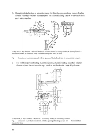
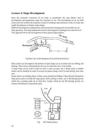
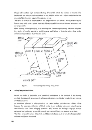
![34
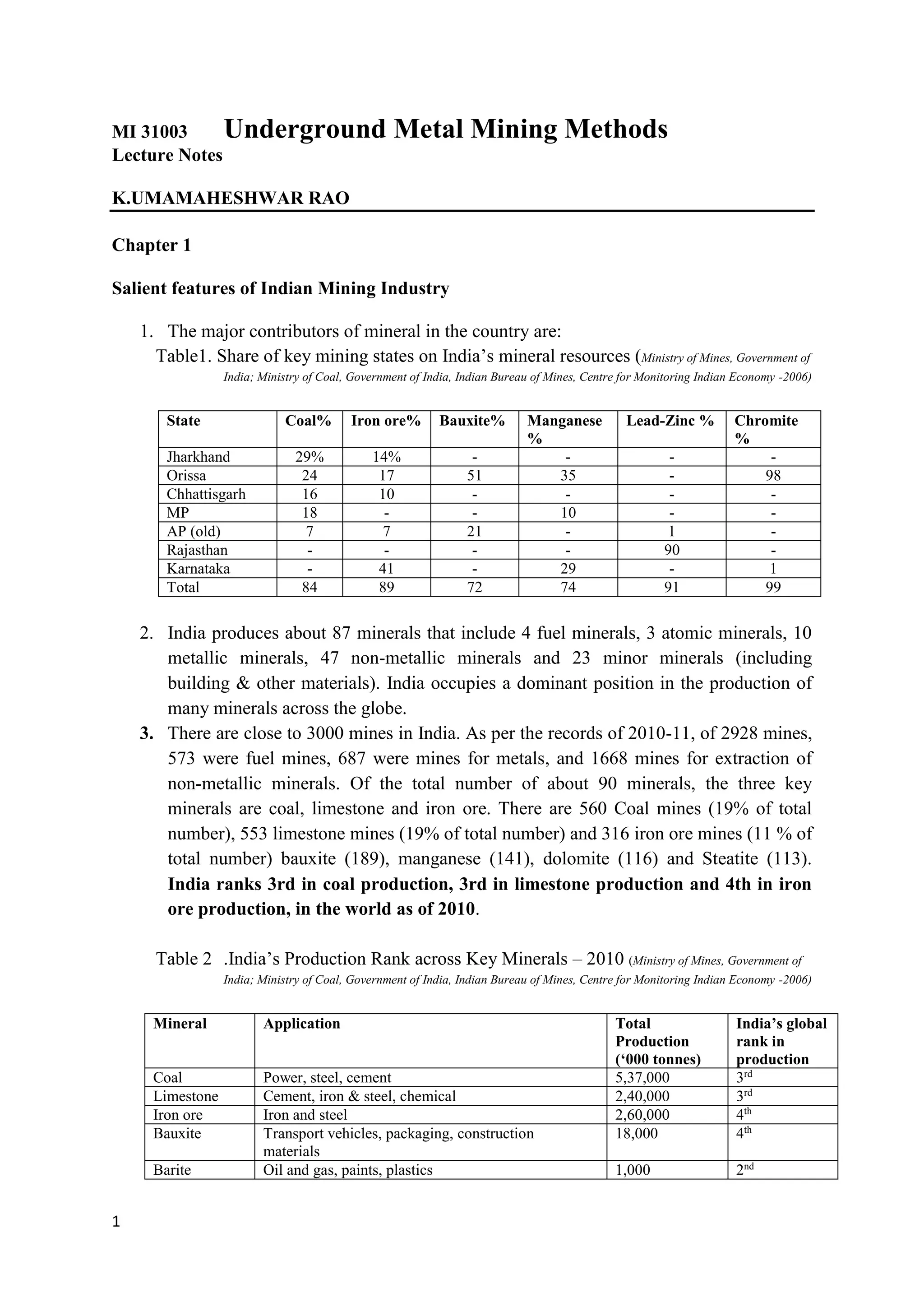
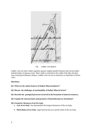
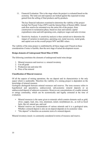
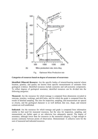
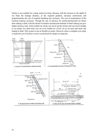
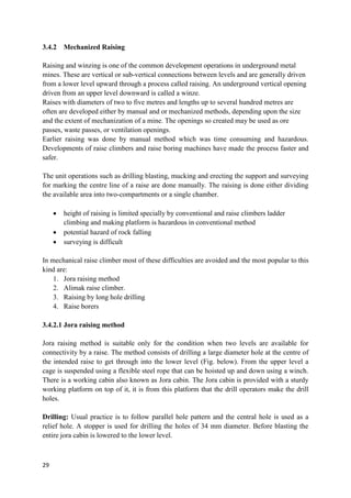
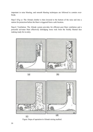
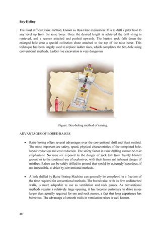
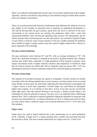
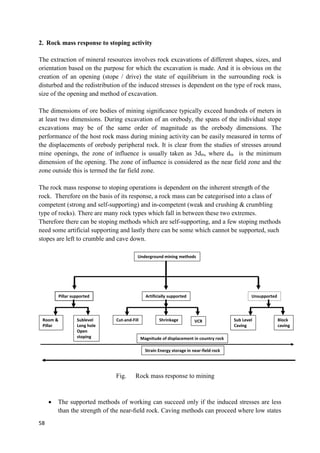
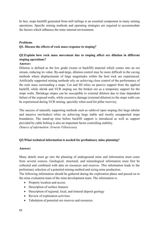
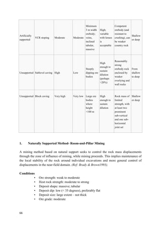
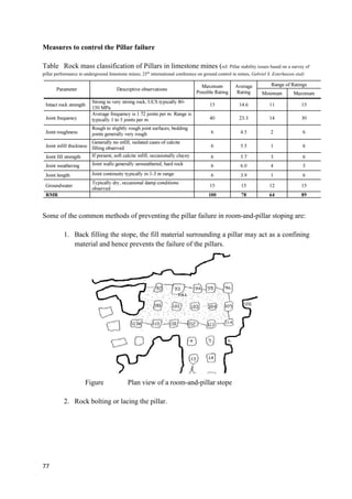
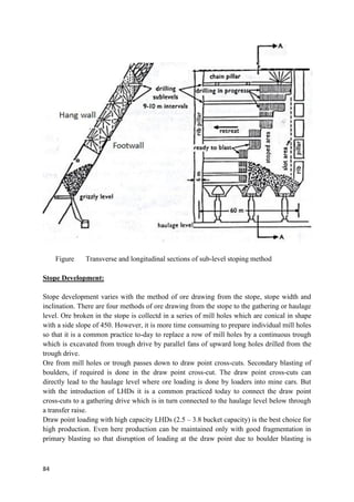
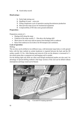
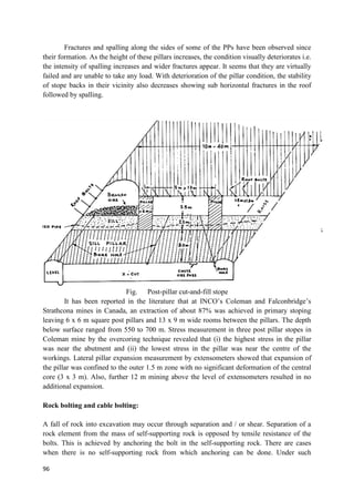
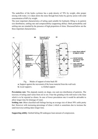
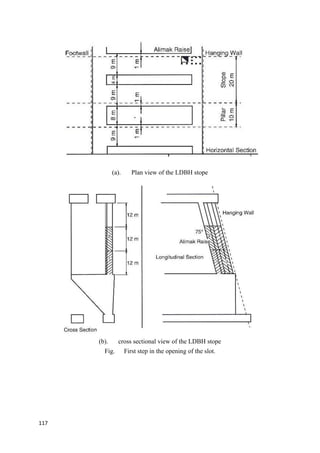
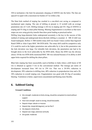
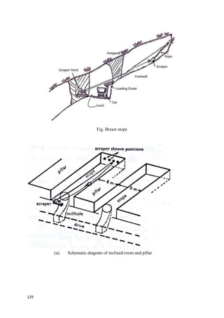
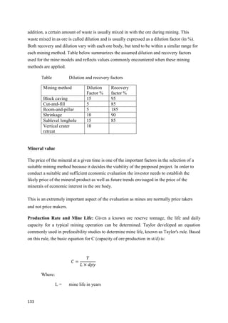
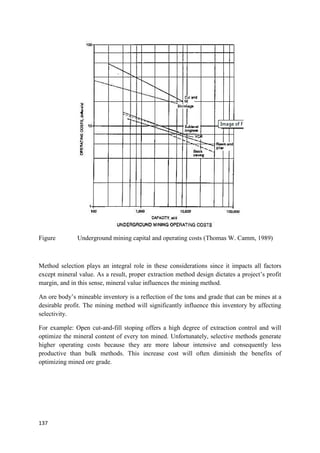
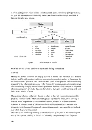
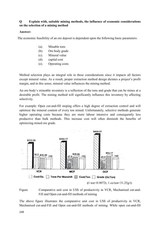
This method has the following advantages:
permits driving of long raises
personal are well protected in a cage under the platform
the miners work from the platform that can be easily adjusted for convenient height
timbering is avoided and stability can be increased by rock bolting if necessary
no danger from falling of rock pieces
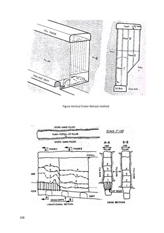
However the cost and other arrangements required cannot justify this for short raises. Figure
above shows complete cycle of raising.
Special feature of Alimak raise climbers:
A. Drive Units:
The raise climber is developed with three kinds of drive units: air driven, electrically driven,
and diesel/hydraulically driven.
Of the different types of Alimak raise climbers, compressed air driven raising is very
common in the country, followed by diesel operated raise climbers are popular.
Air Driven:
In the air driven raise climbers, compressed air comes through a hose. An automatic winch or
reel winds the hose up and down as per the movement of the alimak in the raise construction.
The air motors are effective for raising up to 200m length.
Electrical drive:
Electric are not common in mines, however they have a capacity of driving about 1000m long
raises. The longest vertical raise for ventilation shaft at the Densison mines, Ontario, Canada,
in 1974 [SME-UMM Hand book].
Diesel / Hydraulic drive:
Diesel operated Alimak raises climbers are also common after the compressed air driven
machines. However there is a risk of excess air pollution due to diesel operated machines
underground. The diesel/hydraul;ic driven raise climber can drive more than 1000 m long
raises in one step.](https://image.slidesharecdn.com/dmdlecturenotes-220918065354-366219e4/85/DMD-LECTURE-NOTES-pdf-34-320.jpg)
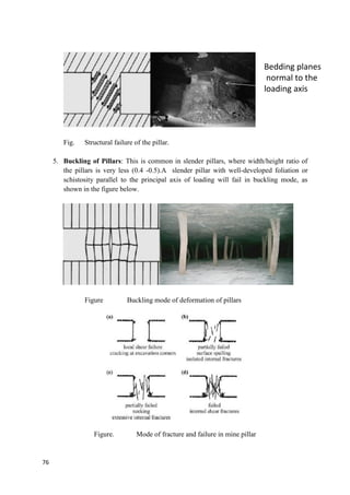
![80
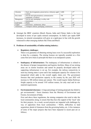
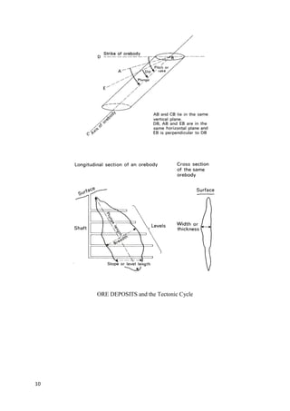
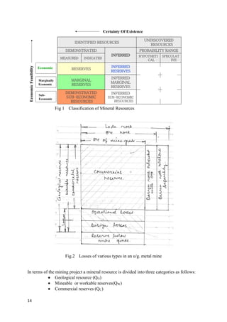
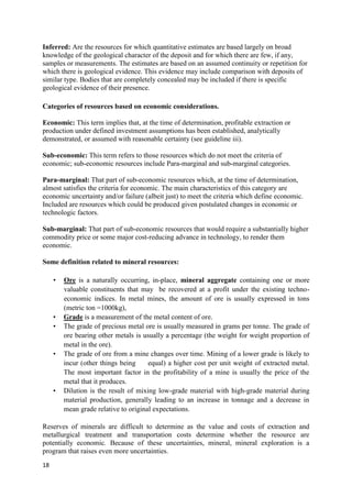
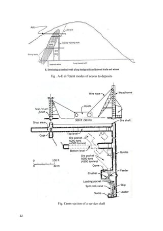
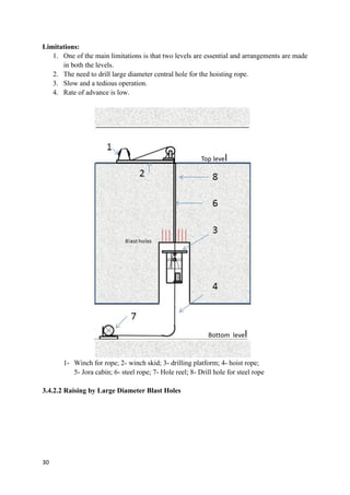
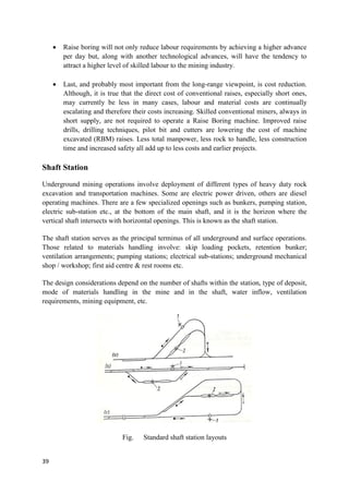
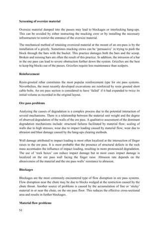
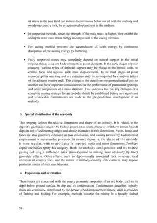
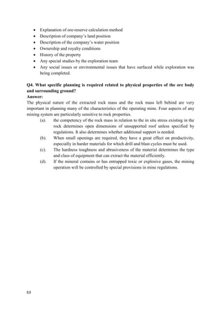
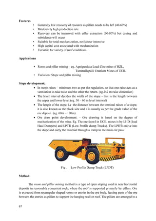
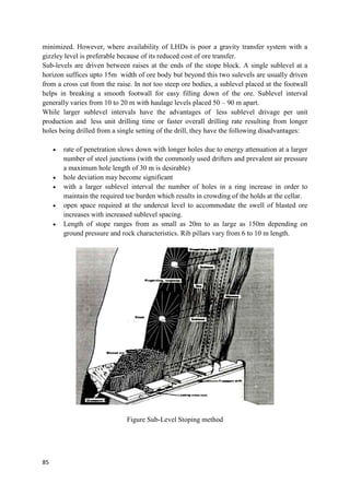
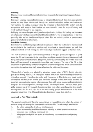
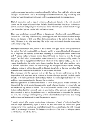
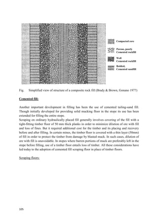
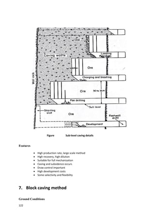
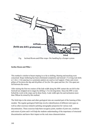
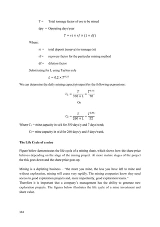
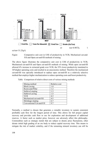
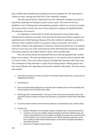
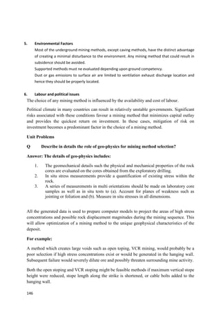
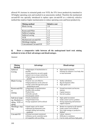
area of ore body. Considering the representative element of the ore body illustrated in the
figure above, the area extraction ration is also defined by
𝑟 = 𝑊
𝑜/(𝑊
𝑜 + 𝑊𝑃)
So that
1 − 𝑟 =
𝑊𝑃
𝑊
𝑜 + 𝑊𝑃
Insertion of this expression in the above equation, yields:
𝜎𝑃 = 𝑃
𝑧𝑧[
1
1 − 𝑟
]
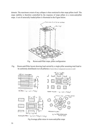
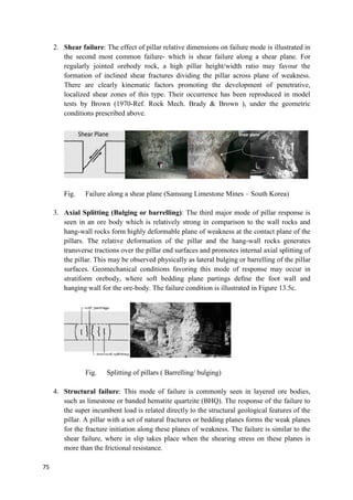
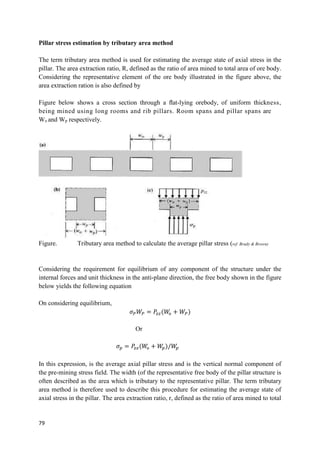
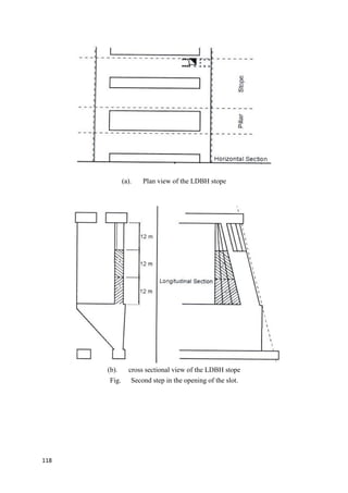
The mining layout shown in the following figure, involving pillars of plan dimensions a and
b, and rooms of span c, may be treated in an analogous way.
The area tributary to a representative pillar is of plan dimensions (a+c), (b+c), so that
satisfaction of the equation for static equilibrium in the vertical direction requires
𝜎𝑃𝑎𝑏 = 𝑃
𝑧𝑧(𝑎 + 𝑐)(𝑏 + 𝑐)
Or
𝜎𝑃 =
𝑃
𝑧𝑧(𝑎 + 𝑐)(𝑏 + 𝑐)
𝑎𝑏
The area extraction ratio is defined by
𝑟 =
[(𝑎 + 𝑐)(𝑏 + 𝑐) − 𝑎𝑏]
(𝑎 + 𝑐)(𝑏 + 𝑐)
With some simple rearrangement the above equation yields the following:
𝜎𝑃 = 𝑃
𝑧𝑧[
1
1 − 𝑟
]](https://image.slidesharecdn.com/dmdlecturenotes-220918065354-366219e4/85/DMD-LECTURE-NOTES-pdf-80-320.jpg)
![81
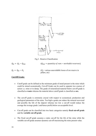
For a square pillar, of plan dimension WpxWp, are separated by rooms of dimension Wo, the
equation is
𝜎𝑃 = 𝑃
𝑧𝑧[(𝑊
𝑜 + 𝑊𝑃)/𝑊𝑃]2
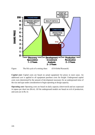
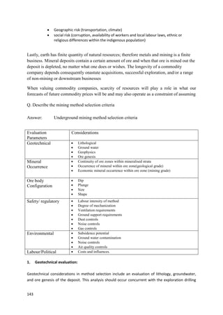
The pillar stress expression given above helps in a rough estimation of the pillar stresses.
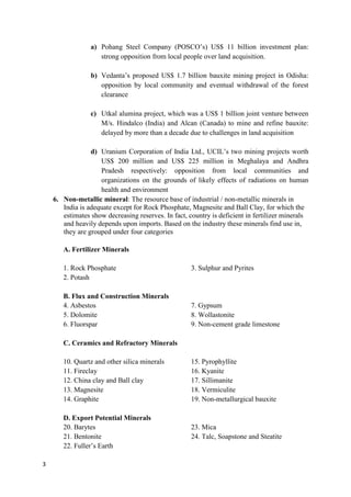
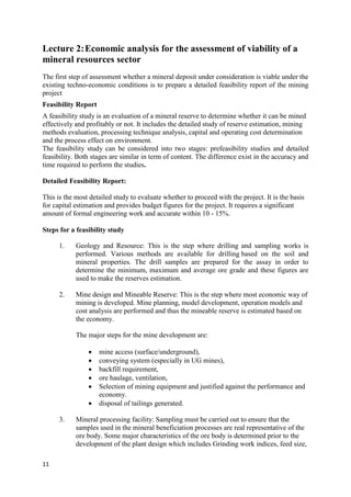
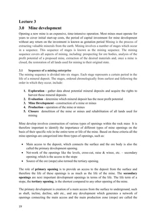
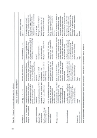
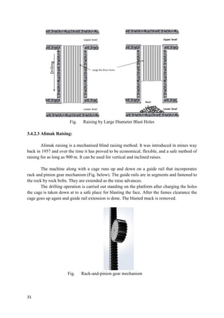
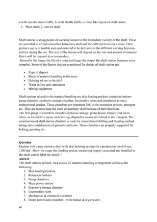
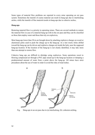
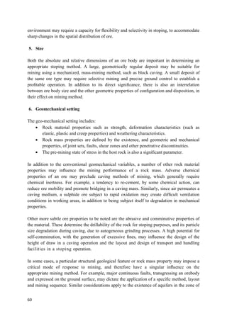
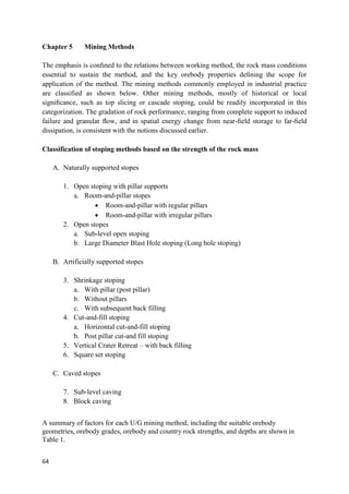
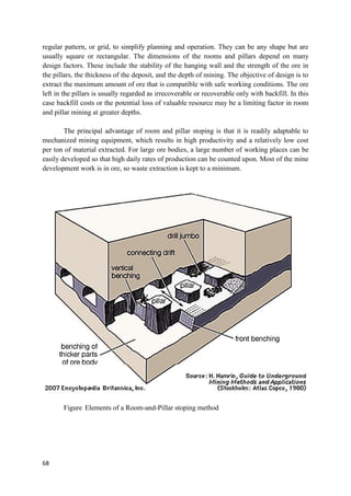
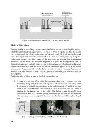
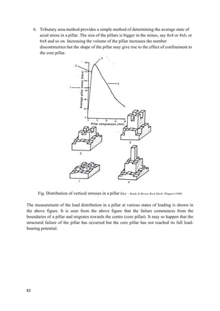
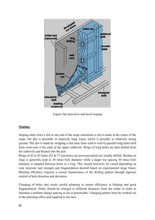
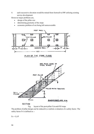
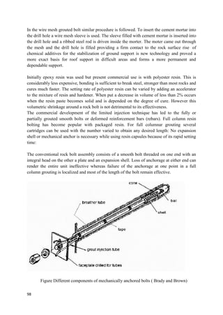
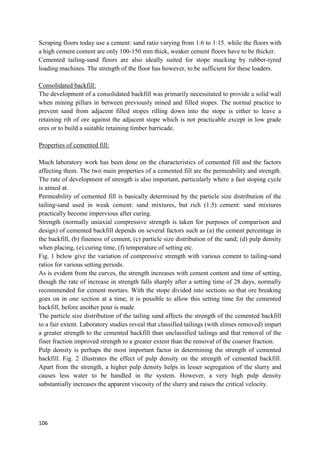
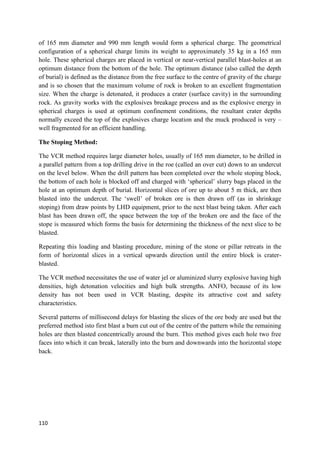
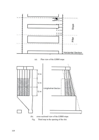
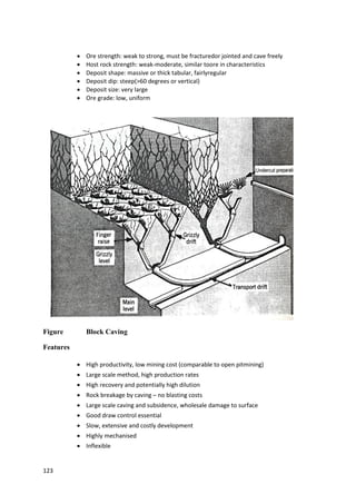
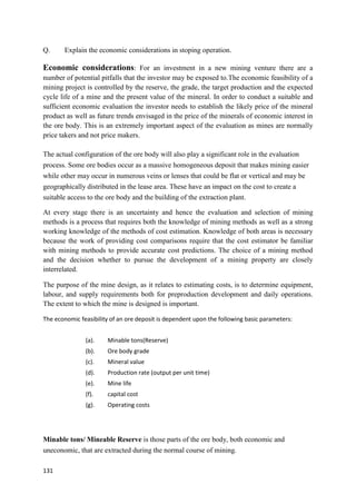
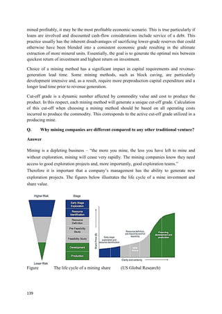
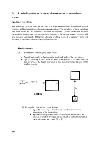
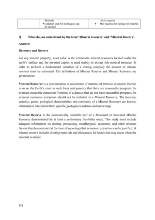
Fig. Relationship between the pillar stresses and the area extraction ratio
The relationship between the pillar stress and the area extraction ratio is illustrated in the
above figure. The main observations from the above graph are that:
1. The average pillar stress is directly proportional to the area extraction ratio and the
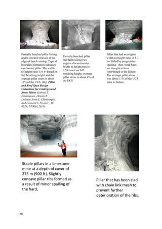
relationship is non-linear.
2. There are two distinct zones in the above relationship, where in the increment in the
pillar stress until r = 0.75, is near linear and the slope is mild, whereas the nonlinear
exponential increment is seen beyond a point where r > 0.75.
3. In the second zone, a very small increase in the extraction ratio is developing a high
increment in the pillar stress.
4. It is therefore inferred that for keeping the stope stable, it is imperative that the
extraction ratio needs to be within the limits of tolerable stress concentration levels, in
the pillar (Factor of safety of the pillar is > 1).
Limitations of Tributary area method
1. The stress estimated by this method represents an average stress within the pillar, and
it is purely a convenient way of representing the state of loading of a pillar in a
direction parallel to the principal stress.
2. Tributary area analysis restricts attention to the pre-mining normal stress (in-situ
stress) component directed parallel to the main axis of the pillar support system.
3. It is assumed that the effect of other stresses in other direction have no effect, which
in reality is not always true.
4. The stress coming on the pillar is the induced stress.
5. Strength of the pillar is related to its volume and geometric shape.
r= 0.75
r= 0.9](https://image.slidesharecdn.com/dmdlecturenotes-220918065354-366219e4/85/DMD-LECTURE-NOTES-pdf-81-320.jpg)

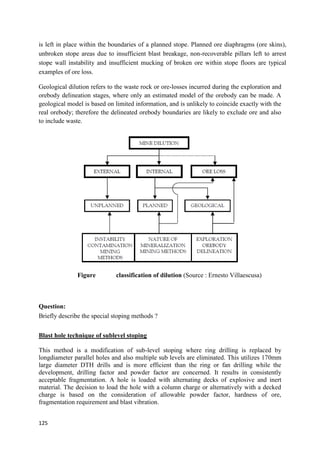

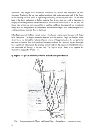
1. India produces many important minerals and ranks highly in global production. Key minerals produced are coal, limestone, and iron ore. Major producing states are Jharkhand, Odisha, Chhattisgarh, Madhya Pradesh, Andhra Pradesh, and Karnataka. 2. Mining in India faces challenges of inadequate infrastructure, difficulties obtaining environmental clearances, and local community opposition. Several large projects have been delayed or withdrawn due to these issues. 3. Ore deposits form through various geological processes including magmatic, hydrothermal, metamorphic, and surficial processes. Theories of ore genesis explain the source of metals, how they are transported, and how they become trapped in