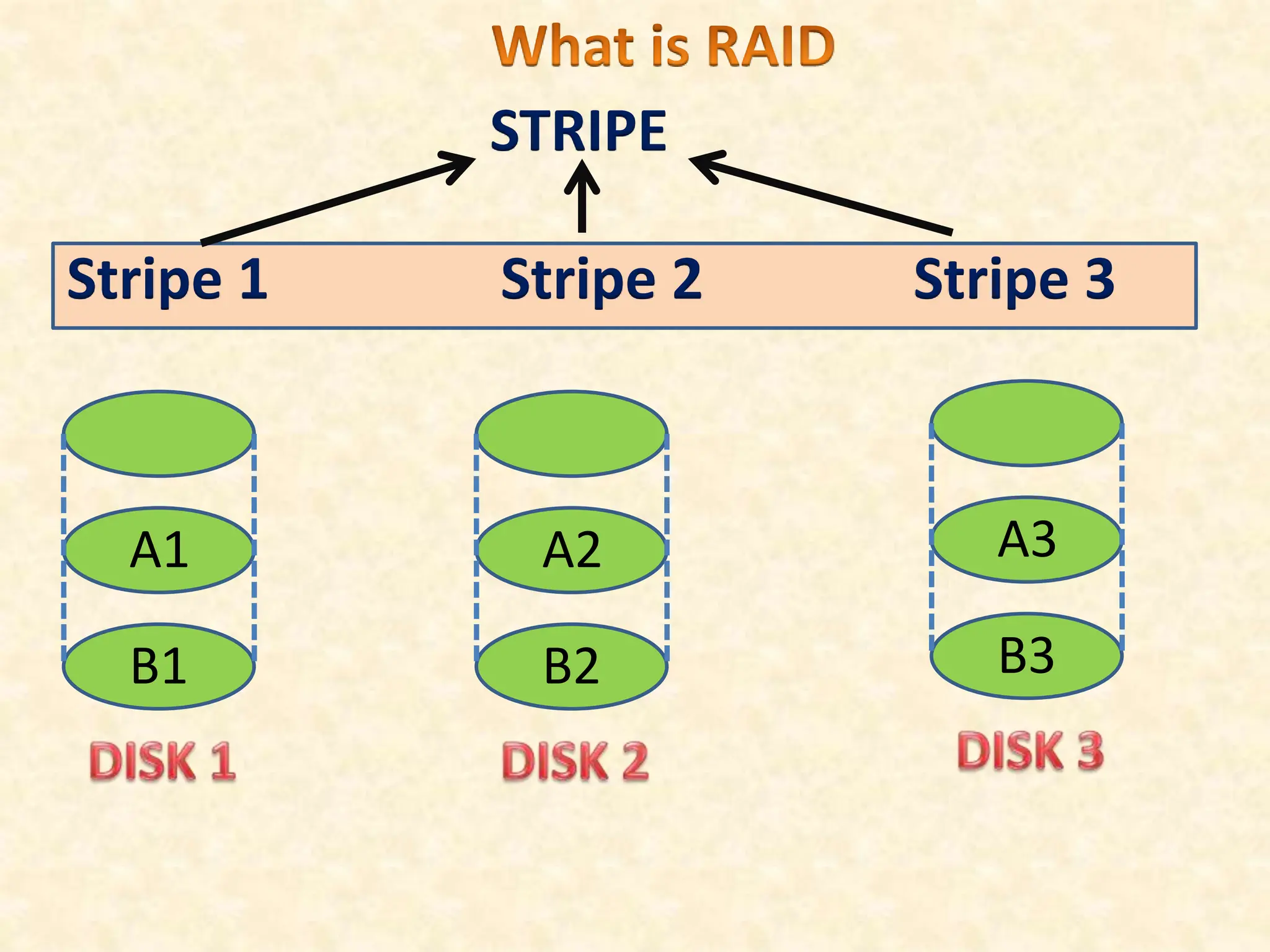
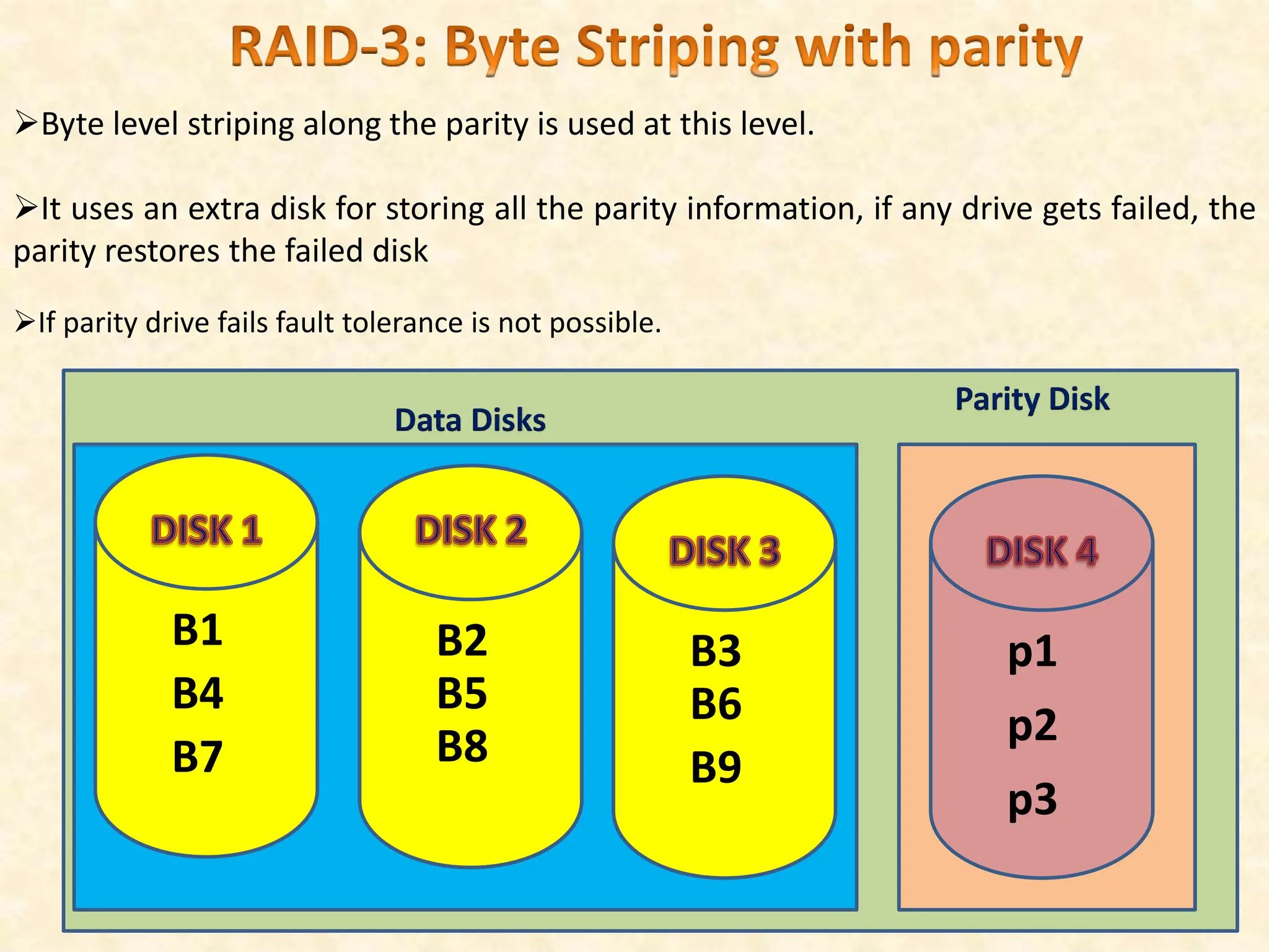
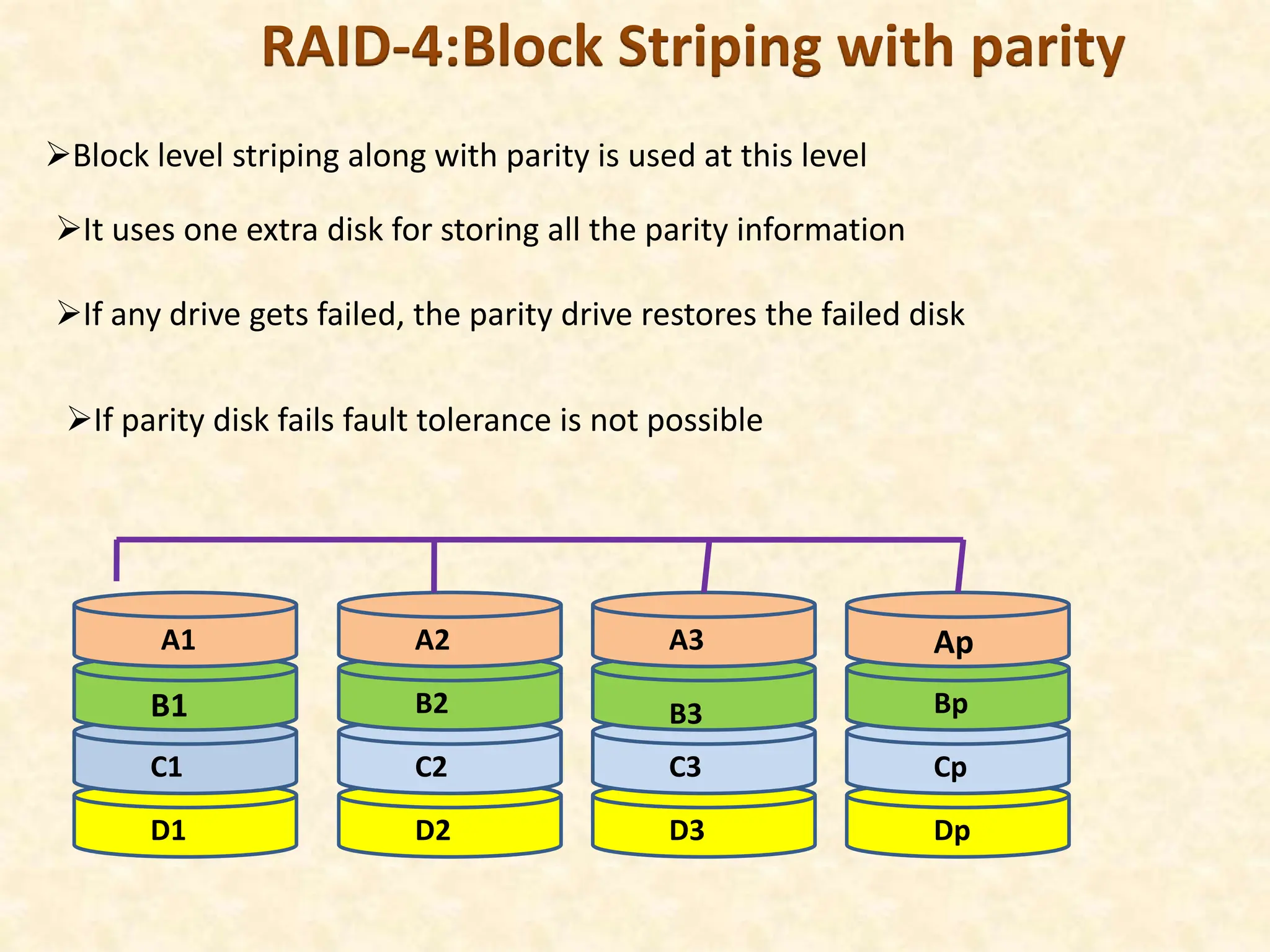
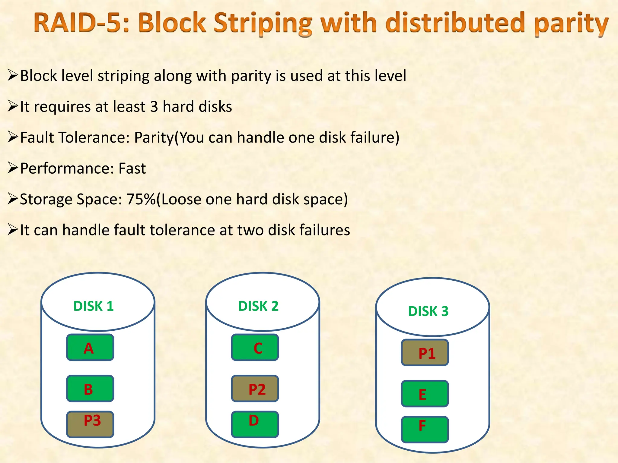
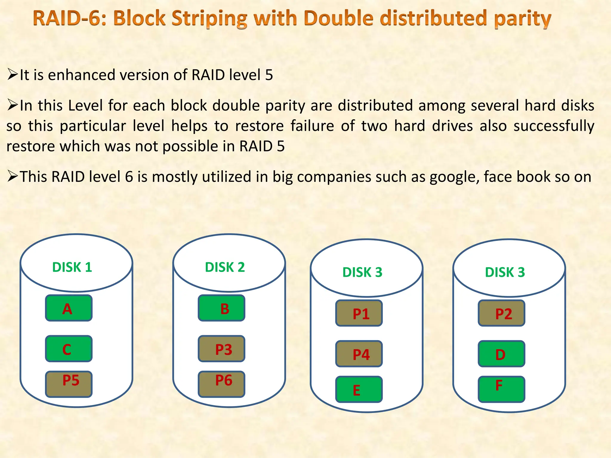
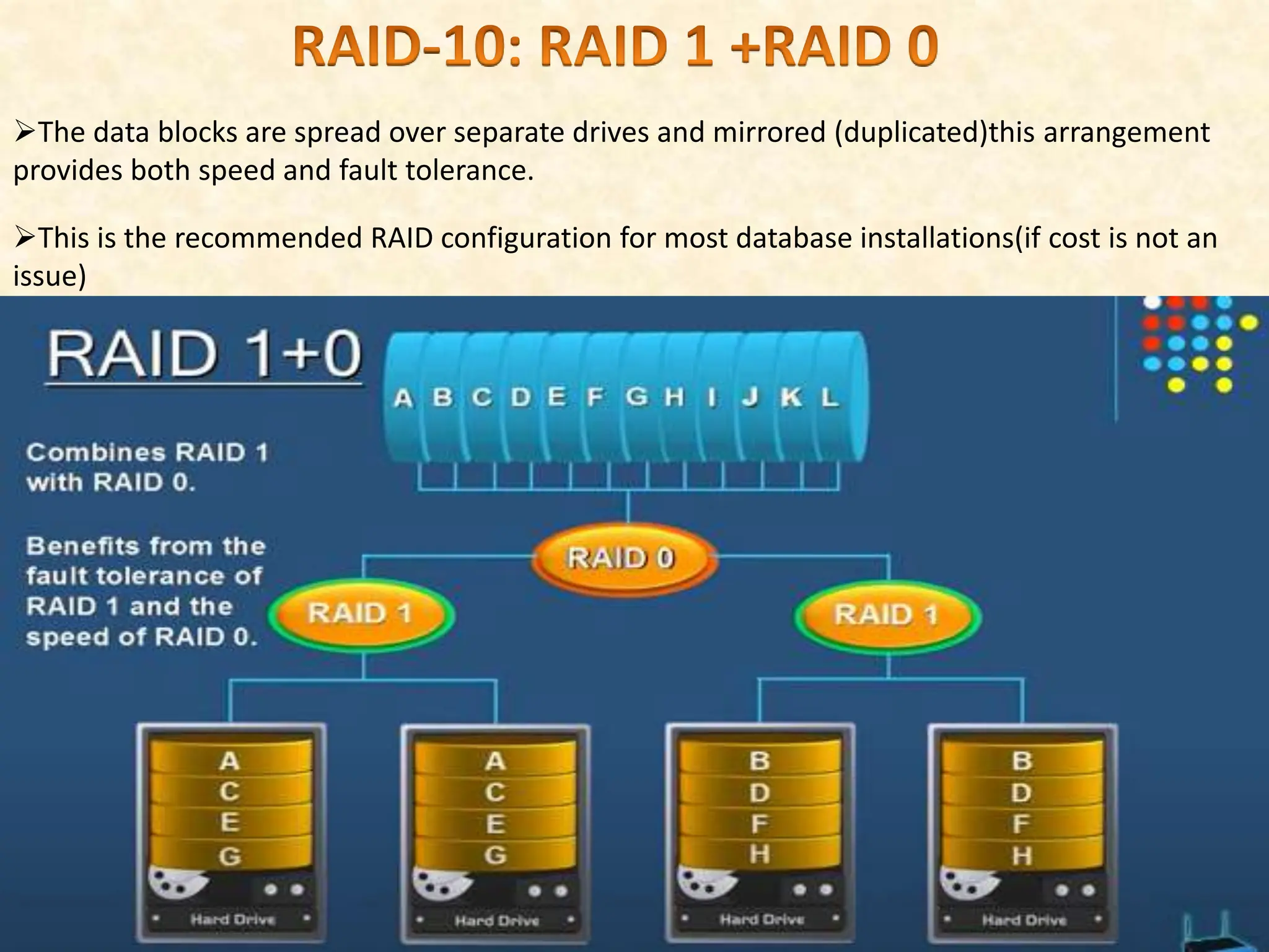
SlideShare a Scribd company logo
1 of 14
Disks are potential bottlenecks for system performance and storage system
reliability. Even though disk performance has been improving continuously,
microprocessor performance has advanced much more rapidly. The performance of
microprocessors has improved at about 50 percent or more per year, but disk access
times have improved at a rate of about 10 percent per year and disk transfer rates at a
rate of about 20percent per year. In addition, since disks contain mechanical elements,
they have much higher failure rates than electronic parts of a computer system. If a
disk fails, all the data stored on it is lost.
A disk array is an arrangement of several disks, organized so as to increase
performance and improve reliability of the resulting storage system. Performance is
increased through data striping.
Data striping distributes data over several disks to give the impression of having a
single large, very fast disk. Reliability is improved through redundancy. Instead of
having a single copy of the data, redundant information is maintained. The redundant
information is carefully organized so that in case of a disk failure, it can be used to
reconstruct the contents of the failed disk.
Disk arrays that implement a combination of data striping and redundancy are called
redundant arrays of independent disks, or in short, RAID.1 Several RAID organizations,
referred to as RAID levels, have been proposed. Each RAID level represents a different
trade-off between reliability and performance. In the remainder of this section, we will
first discuss data striping and redundancy and then introduce the RAID levels that have
become industry standards.
While having more disks increases storage system performance, it also lowers overall
storage system reliability. Assume that the mean-time-to-failure, or MTTF, of a single
disk is 50; 000 hours (about 5:7 years). Then, the MTTF of an array of 100 disks is only
50; 000=100 = 500 hours or about 21 days, assuming that failures occur independently
and that the failure probability of a disk does not change overtime. (Actually, disks
have a higher failure probability early and late in their lifetimes.
Early failures are often due to un detected manufacturing defects; late failures occur
Reliability of a disk array can be increased by storing redundant information. If a disk
failure occurs, the redundant information is used to re construct the data on the failed
disk.
Redundancy can immensely increase the MTTF of a disk array. When incorporating
redundancy into a disk array design, we have to make two choices. First, we have to
decide where to store the redundant information. We can either store the redundant
information on a small number of check disks or we can distribute the redundant
information uniformly over all disks. The second choice we have to make is how to
compute the redundant information .Most disk arrays store parity information: In the
parity scheme, an extra check disk contains information that can be used to recover
from failure of any one disk in the array.
Assume that we have a disk array with D disks and consider the first bit on each data
disk. Suppose that i of the D data bits are one. The first bit on the check disk is set to
one if i is odd, otherwise it is set to zero. This bit on the check disk is called the parity
of the data bits. The check disk contains parity information for each set of
corresponding D data bits.In a RAID system, the disk array is partitioned into reliability
groups, where a reliability group consists of a set of data disks and a set of check disks.
A common redundancy scheme (see box) is applied to each group. The number of
check disks depends on the RAID level chosen. In the remainder of this section, we
assume for ease of explanation that there is only one reliability group. The reader
should keep in mind that actual RAID implementations consist of several reliability
groups, and that the number of groups plays a role in the overall reliability of the
Most of our systems we are having one hard disk for storing the data if due to any mechanical
failure or some disk failure it may be that hard disk will get corrupt and all our data get lost. So
what could be the solution we could replace a single hard disk with multiple hard drives so what
will be the advantage of this, our data will remain secure our data for a longer time. How will
define the RAID now? RAID is nothing but redundant array of inexpensive or independent
disks. What is the advantage of using of RAID? In this system, because of failure one hard disk
data loss does not take place;
RAID is collection of various disk organization techniques.
It is used to get better disk performance, reliability or both.
RAID can be structured in many ways, there many levels of RAID such as RAID 0,1,2,34,5,6,10
Before Discussing about RAIDS first we need to about Data Striping?
Data striping is the technique of splitting the data for spreading the data across
multiple hard drives.
The division of data can be done at 3 levels.
Bit Level
Byte Level(1 byte=8bits)
Block Level(Group of number of bytes)
A1
B1
A2
B2
A3
B3
STRIPE
Stripe 1 Stripe 2 Stripe 3
RAID-0:Data Striping
BLOCK 1
BLOCK 3
BLOCK 5
BLOCK 7
BLOCK 2
BLOCK 4
BLOCK 6
BLOCK 8
RAID-0
DRIVE 1 DRIVE 2
Block data Striping
Fault Tolerance=None(means of our hard disk fails we lost the data)
Performance: Fast
Storage Space=100% (consider both hard drives have 50 GB each that could be
used to 100 GB utilized to storing the data.
RAID-1:Mirroring
BLOCK 1
BLOCK 2
BLOCK 3
BLOCK 4
BLOCK 1
BLOCK 2
BLOCK 3
BLOCK 4
RAID-1
DRIVE 1 DRIVE 2
It uses the concept of mirroring; what is mirroring? Means is written identically
to two drives(mirror set).
Required at least 2 disks
Advantage:
Fault Tolerance: Mirrored Set(it means if any one hard disk failed we can replace
with new hard disk in place of old one, here we can’t lost the data even one hard
disk failed.
Disadvantage:
Performance: 50%: Because if one disk is allocated for backup of the another disk so it
occupies extra 50% space.
RAID-2
A1
B1
C1
D1
Use of Mirroring as well as stores error correcting codes for its data striped on
different disks
It is bit level striping hamming ECC
Each data bit in a word is recorded on a separated disk and ECC codes of the data
words are stored on a set disks
Due to its complex structure and high cost RAID 2 not commercially available
A2
B2
C2
D3
A3
B3
C3
D3
A0
B0
C0
D0
ECC/Ax
ECC/Bx
ECC/Cx
ECC/Dx
ECC/Ay
ECC/By
ECC/Cy
ECC/Dy
ECC/Az
ECC/Bz
ECC/Cz
ECC/Dz
Byte level striping along the parity is used at this level.
It uses an extra disk for storing all the parity information, if any drive gets failed, the
parity restores the failed disk
If parity drive fails fault tolerance is not possible.
Data Disks
Parity Disk
B1 B2 B3
B4
B7
B5
B8
B6
B9
p1
p2
p3
RAID-4:Block Striping with parity
A1
B1
C1
D1
A2
B2
C2
D2
Block level striping along with parity is used at this level
It uses one extra disk for storing all the parity information
A3
B3
C3
D3
Ap
Bp
Cp
Dp
If any drive gets failed, the parity drive restores the failed disk
If parity disk fails fault tolerance is not possible
Block level striping along with parity is used at this level
It requires at least 3 hard disks
Fault Tolerance: Parity(You can handle one disk failure)
Performance: Fast
Storage Space: 75%(Loose one hard disk space)
It can handle fault tolerance at two disk failures
DISK 1
A
B
P3
DISK 2
C
P2
D
DISK 3
P1
E
F
It is enhanced version of RAID level 5
In this Level for each block double parity are distributed among several hard disks
so this particular level helps to restore failure of two hard drives also successfully
restore which was not possible in RAID 5
This RAID level 6 is mostly utilized in big companies such as google, face book so on
DISK 1
A
C
P5
DISK 2
B
P3
P6
DISK 3
P1
P4
E
DISK 3
P2
D
F
The data blocks are spread over separate drives and mirrored (duplicated)this arrangement
provides both speed and fault tolerance.
This is the recommended RAID configuration for most database installations(if cost is not an
issue)
If data loss is not an issue, RAID Level 0 improves overall system performance at the
lowest cost. RAID Level 0+1 is superior to RAID Level 1. The main application areas for
RAID Level 0+1 systems are small storage subsystems where the cost of mirroring is
moderate. Sometimes RAID Level 0+1 is used for applications that have a high
percentage of writes in their workload, since RAID Level 0+1 provides the best write
performance. RAID levels 2 and 4 are always inferior to RAID levels 3 and 5,
respectively. RAID Level 3 is appropriate for workloads consisting mainly of large
transfer requests of several contiguous blocks. The performance of a RAID Level 3
system is bad for workloads

More Related Content

Similar to disk structure and multiple RAID levels .ppt

Storage systems reliability
Storage systems reliabilityStorage systems reliability
Storage systems reliabilityJuha Salenius
 
Exercise 3-1 This chapter’s opening scenario illustrates a specific .docx
Exercise 3-1 This chapter’s opening scenario illustrates a specific .docxExercise 3-1 This chapter’s opening scenario illustrates a specific .docx
Exercise 3-1 This chapter’s opening scenario illustrates a specific .docxnealwaters20034
 
Flash-Specific Data Protection
Flash-Specific Data ProtectionFlash-Specific Data Protection
Flash-Specific Data ProtectionEMC
 
Dr module 3 assignment Management homework help.docx
Dr module 3 assignment Management homework help.docxDr module 3 assignment Management homework help.docx
Dr module 3 assignment Management homework help.docxwrite31
 
112667416 raid-seminar
112667416 raid-seminar112667416 raid-seminar
112667416 raid-seminarabhivicram
 
Present of Raid and Its Type
Present of Raid and Its TypePresent of Raid and Its Type
Present of Raid and Its TypeUsama ahmad
 
Chapter 8 - Multimedia Storage and Retrieval
Chapter 8 - Multimedia Storage and RetrievalChapter 8 - Multimedia Storage and Retrieval
Chapter 8 - Multimedia Storage and RetrievalPratik Pradhan
 

Similar to disk structure and multiple RAID levels .ppt (20)

Raid in SNA
Raid in SNA Raid in SNA
Raid in SNA
 
Storage systems reliability
Storage systems reliabilityStorage systems reliability
Storage systems reliability
 
Database 3
Database 3Database 3
Database 3
 
Raid technology
Raid technologyRaid technology
Raid technology
 
Raid
Raid Raid
Raid
 
Exercise 3-1 This chapter’s opening scenario illustrates a specific .docx
Exercise 3-1 This chapter’s opening scenario illustrates a specific .docxExercise 3-1 This chapter’s opening scenario illustrates a specific .docx
Exercise 3-1 This chapter’s opening scenario illustrates a specific .docx
 
RAID
RAIDRAID
RAID
 
Flash-Specific Data Protection
Flash-Specific Data ProtectionFlash-Specific Data Protection
Flash-Specific Data Protection
 
data recovery-raid
data recovery-raiddata recovery-raid
data recovery-raid
 
Dr module 3 assignment Management homework help.docx
Dr module 3 assignment Management homework help.docxDr module 3 assignment Management homework help.docx
Dr module 3 assignment Management homework help.docx
 
Raid
RaidRaid
Raid
 
Raid Recovery
Raid RecoveryRaid Recovery
Raid Recovery
 
Raid(Storage Technology)
Raid(Storage Technology)Raid(Storage Technology)
Raid(Storage Technology)
 
RAID seminar
RAID seminarRAID seminar
RAID seminar
 
112667416 raid-seminar
112667416 raid-seminar112667416 raid-seminar
112667416 raid-seminar
 
RAID LEVELS
RAID LEVELSRAID LEVELS
RAID LEVELS
 
Present of Raid and Its Type
Present of Raid and Its TypePresent of Raid and Its Type
Present of Raid and Its Type
 
Understanding RAID Controller
Understanding RAID ControllerUnderstanding RAID Controller
Understanding RAID Controller
 
Linux admin
Linux adminLinux admin
Linux admin
 
Chapter 8 - Multimedia Storage and Retrieval
Chapter 8 - Multimedia Storage and RetrievalChapter 8 - Multimedia Storage and Retrieval
Chapter 8 - Multimedia Storage and Retrieval
 

Recently uploaded

Introduction to Data Visualization,Matplotlib.pdf
Introduction to Data Visualization,Matplotlib.pdfIntroduction to Data Visualization,Matplotlib.pdf
Introduction to Data Visualization,Matplotlib.pdfsumitt6_25730773
 
Unit 4_Part 1 CSE2001 Exception Handling and Function Template and Class Temp...
Unit 4_Part 1 CSE2001 Exception Handling and Function Template and Class Temp...Unit 4_Part 1 CSE2001 Exception Handling and Function Template and Class Temp...
Unit 4_Part 1 CSE2001 Exception Handling and Function Template and Class Temp...drmkjayanthikannan
 
1_Introduction + EAM Vocabulary + how to navigate in EAM.pdf
1_Introduction + EAM Vocabulary + how to navigate in EAM.pdf1_Introduction + EAM Vocabulary + how to navigate in EAM.pdf
1_Introduction + EAM Vocabulary + how to navigate in EAM.pdfAldoGarca30
 
HOA1&2 - Module 3 - PREHISTORCI ARCHITECTURE OF KERALA.pptx
HOA1&2 - Module 3 - PREHISTORCI ARCHITECTURE OF KERALA.pptxHOA1&2 - Module 3 - PREHISTORCI ARCHITECTURE OF KERALA.pptx
HOA1&2 - Module 3 - PREHISTORCI ARCHITECTURE OF KERALA.pptxSCMS School of Architecture
 
XXXXXXXXXXXXXXXXXXXXXXXXXXXXXXXXXXXXXXXXXXXXXXXXXXXX
XXXXXXXXXXXXXXXXXXXXXXXXXXXXXXXXXXXXXXXXXXXXXXXXXXXXXXXXXXXXXXXXXXXXXXXXXXXXXXXXXXXXXXXXXXXXXXXXXXXXXXXX
XXXXXXXXXXXXXXXXXXXXXXXXXXXXXXXXXXXXXXXXXXXXXXXXXXXXssuser89054b
 
Digital Communication Essentials: DPCM, DM, and ADM .pptx
Digital Communication Essentials: DPCM, DM, and ADM .pptxDigital Communication Essentials: DPCM, DM, and ADM .pptx
Digital Communication Essentials: DPCM, DM, and ADM .pptxpritamlangde
 
Computer Networks Basics of Network Devices
Computer Networks  Basics of Network DevicesComputer Networks  Basics of Network Devices
Computer Networks Basics of Network DevicesChandrakantDivate1
 
Employee leave management system project.
Employee leave management system project.Employee leave management system project.
Employee leave management system project.Kamal Acharya
 
HAND TOOLS USED AT ELECTRONICS WORK PRESENTED BY KOUSTAV SARKAR
HAND TOOLS USED AT ELECTRONICS WORK PRESENTED BY KOUSTAV SARKARHAND TOOLS USED AT ELECTRONICS WORK PRESENTED BY KOUSTAV SARKAR
HAND TOOLS USED AT ELECTRONICS WORK PRESENTED BY KOUSTAV SARKARKOUSTAV SARKAR
 
Theory of Time 2024 (Universal Theory for Everything)
Theory of Time 2024 (Universal Theory for Everything)Theory of Time 2024 (Universal Theory for Everything)
Theory of Time 2024 (Universal Theory for Everything)Ramkumar k
 
NO1 Top No1 Amil Baba In Azad Kashmir, Kashmir Black Magic Specialist Expert ...
NO1 Top No1 Amil Baba In Azad Kashmir, Kashmir Black Magic Specialist Expert ...NO1 Top No1 Amil Baba In Azad Kashmir, Kashmir Black Magic Specialist Expert ...
NO1 Top No1 Amil Baba In Azad Kashmir, Kashmir Black Magic Specialist Expert ...Amil baba
 
Design For Accessibility: Getting it right from the start
Design For Accessibility: Getting it right from the startDesign For Accessibility: Getting it right from the start
Design For Accessibility: Getting it right from the startQuintin Balsdon
 
8086 Microprocessor Architecture: 16-bit microprocessor
8086 Microprocessor Architecture: 16-bit microprocessor8086 Microprocessor Architecture: 16-bit microprocessor
8086 Microprocessor Architecture: 16-bit microprocessorAshwiniTodkar4
 
Ground Improvement Technique: Earth Reinforcement
Ground Improvement Technique: Earth ReinforcementGround Improvement Technique: Earth Reinforcement
Ground Improvement Technique: Earth ReinforcementDr. Deepak Mudgal
 
UNIT 4 PTRP final Convergence in probability.pptx
UNIT 4 PTRP final Convergence in probability.pptxUNIT 4 PTRP final Convergence in probability.pptx
UNIT 4 PTRP final Convergence in probability.pptxkalpana413121
 
School management system project Report.pdf
School management system project Report.pdfSchool management system project Report.pdf
School management system project Report.pdfKamal Acharya
 
Standard vs Custom Battery Packs - Decoding the Power Play
Standard vs Custom Battery Packs - Decoding the Power PlayStandard vs Custom Battery Packs - Decoding the Power Play
Standard vs Custom Battery Packs - Decoding the Power PlayEpec Engineered Technologies
 
S1S2 B.Arch MGU - HOA1&2 Module 3 -Temple Architecture of Kerala.pptx
S1S2 B.Arch MGU - HOA1&2 Module 3 -Temple Architecture of Kerala.pptxS1S2 B.Arch MGU - HOA1&2 Module 3 -Temple Architecture of Kerala.pptx
S1S2 B.Arch MGU - HOA1&2 Module 3 -Temple Architecture of Kerala.pptxSCMS School of Architecture
 
Introduction to Robotics in Mechanical Engineering.pptx
Introduction to Robotics in Mechanical Engineering.pptxIntroduction to Robotics in Mechanical Engineering.pptx
Introduction to Robotics in Mechanical Engineering.pptxhublikarsn
 

Recently uploaded (20)

Introduction to Data Visualization,Matplotlib.pdf
Introduction to Data Visualization,Matplotlib.pdfIntroduction to Data Visualization,Matplotlib.pdf
Introduction to Data Visualization,Matplotlib.pdf
 
Unit 4_Part 1 CSE2001 Exception Handling and Function Template and Class Temp...
Unit 4_Part 1 CSE2001 Exception Handling and Function Template and Class Temp...Unit 4_Part 1 CSE2001 Exception Handling and Function Template and Class Temp...
Unit 4_Part 1 CSE2001 Exception Handling and Function Template and Class Temp...
 
1_Introduction + EAM Vocabulary + how to navigate in EAM.pdf
1_Introduction + EAM Vocabulary + how to navigate in EAM.pdf1_Introduction + EAM Vocabulary + how to navigate in EAM.pdf
1_Introduction + EAM Vocabulary + how to navigate in EAM.pdf
 
HOA1&2 - Module 3 - PREHISTORCI ARCHITECTURE OF KERALA.pptx
HOA1&2 - Module 3 - PREHISTORCI ARCHITECTURE OF KERALA.pptxHOA1&2 - Module 3 - PREHISTORCI ARCHITECTURE OF KERALA.pptx
HOA1&2 - Module 3 - PREHISTORCI ARCHITECTURE OF KERALA.pptx
 
XXXXXXXXXXXXXXXXXXXXXXXXXXXXXXXXXXXXXXXXXXXXXXXXXXXX
XXXXXXXXXXXXXXXXXXXXXXXXXXXXXXXXXXXXXXXXXXXXXXXXXXXXXXXXXXXXXXXXXXXXXXXXXXXXXXXXXXXXXXXXXXXXXXXXXXXXXXXX
XXXXXXXXXXXXXXXXXXXXXXXXXXXXXXXXXXXXXXXXXXXXXXXXXXXX
 
Digital Communication Essentials: DPCM, DM, and ADM .pptx
Digital Communication Essentials: DPCM, DM, and ADM .pptxDigital Communication Essentials: DPCM, DM, and ADM .pptx
Digital Communication Essentials: DPCM, DM, and ADM .pptx
 
Computer Networks Basics of Network Devices
Computer Networks  Basics of Network DevicesComputer Networks  Basics of Network Devices
Computer Networks Basics of Network Devices
 
Employee leave management system project.
Employee leave management system project.Employee leave management system project.
Employee leave management system project.
 
HAND TOOLS USED AT ELECTRONICS WORK PRESENTED BY KOUSTAV SARKAR
HAND TOOLS USED AT ELECTRONICS WORK PRESENTED BY KOUSTAV SARKARHAND TOOLS USED AT ELECTRONICS WORK PRESENTED BY KOUSTAV SARKAR
HAND TOOLS USED AT ELECTRONICS WORK PRESENTED BY KOUSTAV SARKAR
 
Theory of Time 2024 (Universal Theory for Everything)
Theory of Time 2024 (Universal Theory for Everything)Theory of Time 2024 (Universal Theory for Everything)
Theory of Time 2024 (Universal Theory for Everything)
 
NO1 Top No1 Amil Baba In Azad Kashmir, Kashmir Black Magic Specialist Expert ...
NO1 Top No1 Amil Baba In Azad Kashmir, Kashmir Black Magic Specialist Expert ...NO1 Top No1 Amil Baba In Azad Kashmir, Kashmir Black Magic Specialist Expert ...
NO1 Top No1 Amil Baba In Azad Kashmir, Kashmir Black Magic Specialist Expert ...
 
Design For Accessibility: Getting it right from the start
Design For Accessibility: Getting it right from the startDesign For Accessibility: Getting it right from the start
Design For Accessibility: Getting it right from the start
 
8086 Microprocessor Architecture: 16-bit microprocessor
8086 Microprocessor Architecture: 16-bit microprocessor8086 Microprocessor Architecture: 16-bit microprocessor
8086 Microprocessor Architecture: 16-bit microprocessor
 
Ground Improvement Technique: Earth Reinforcement
Ground Improvement Technique: Earth ReinforcementGround Improvement Technique: Earth Reinforcement
Ground Improvement Technique: Earth Reinforcement
 
UNIT 4 PTRP final Convergence in probability.pptx
UNIT 4 PTRP final Convergence in probability.pptxUNIT 4 PTRP final Convergence in probability.pptx
UNIT 4 PTRP final Convergence in probability.pptx
 
Cara Menggugurkan Sperma Yang Masuk Rahim Biyar Tidak Hamil
Cara Menggugurkan Sperma Yang Masuk Rahim Biyar Tidak HamilCara Menggugurkan Sperma Yang Masuk Rahim Biyar Tidak Hamil
Cara Menggugurkan Sperma Yang Masuk Rahim Biyar Tidak Hamil
 
School management system project Report.pdf
School management system project Report.pdfSchool management system project Report.pdf
School management system project Report.pdf
 
Standard vs Custom Battery Packs - Decoding the Power Play
Standard vs Custom Battery Packs - Decoding the Power PlayStandard vs Custom Battery Packs - Decoding the Power Play
Standard vs Custom Battery Packs - Decoding the Power Play
 
S1S2 B.Arch MGU - HOA1&2 Module 3 -Temple Architecture of Kerala.pptx
S1S2 B.Arch MGU - HOA1&2 Module 3 -Temple Architecture of Kerala.pptxS1S2 B.Arch MGU - HOA1&2 Module 3 -Temple Architecture of Kerala.pptx
S1S2 B.Arch MGU - HOA1&2 Module 3 -Temple Architecture of Kerala.pptx
 
Introduction to Robotics in Mechanical Engineering.pptx
Introduction to Robotics in Mechanical Engineering.pptxIntroduction to Robotics in Mechanical Engineering.pptx
Introduction to Robotics in Mechanical Engineering.pptx
 

disk structure and multiple RAID levels .ppt

  • 1. Disks are potential bottlenecks for system performance and storage system reliability. Even though disk performance has been improving continuously, microprocessor performance has advanced much more rapidly. The performance of microprocessors has improved at about 50 percent or more per year, but disk access times have improved at a rate of about 10 percent per year and disk transfer rates at a rate of about 20percent per year. In addition, since disks contain mechanical elements, they have much higher failure rates than electronic parts of a computer system. If a disk fails, all the data stored on it is lost. A disk array is an arrangement of several disks, organized so as to increase performance and improve reliability of the resulting storage system. Performance is increased through data striping. Data striping distributes data over several disks to give the impression of having a single large, very fast disk. Reliability is improved through redundancy. Instead of having a single copy of the data, redundant information is maintained. The redundant information is carefully organized so that in case of a disk failure, it can be used to reconstruct the contents of the failed disk.
  • 2. Disk arrays that implement a combination of data striping and redundancy are called redundant arrays of independent disks, or in short, RAID.1 Several RAID organizations, referred to as RAID levels, have been proposed. Each RAID level represents a different trade-off between reliability and performance. In the remainder of this section, we will first discuss data striping and redundancy and then introduce the RAID levels that have become industry standards. While having more disks increases storage system performance, it also lowers overall storage system reliability. Assume that the mean-time-to-failure, or MTTF, of a single disk is 50; 000 hours (about 5:7 years). Then, the MTTF of an array of 100 disks is only 50; 000=100 = 500 hours or about 21 days, assuming that failures occur independently and that the failure probability of a disk does not change overtime. (Actually, disks have a higher failure probability early and late in their lifetimes. Early failures are often due to un detected manufacturing defects; late failures occur Reliability of a disk array can be increased by storing redundant information. If a disk failure occurs, the redundant information is used to re construct the data on the failed disk.
  • 3. Redundancy can immensely increase the MTTF of a disk array. When incorporating redundancy into a disk array design, we have to make two choices. First, we have to decide where to store the redundant information. We can either store the redundant information on a small number of check disks or we can distribute the redundant information uniformly over all disks. The second choice we have to make is how to compute the redundant information .Most disk arrays store parity information: In the parity scheme, an extra check disk contains information that can be used to recover from failure of any one disk in the array. Assume that we have a disk array with D disks and consider the first bit on each data disk. Suppose that i of the D data bits are one. The first bit on the check disk is set to one if i is odd, otherwise it is set to zero. This bit on the check disk is called the parity of the data bits. The check disk contains parity information for each set of corresponding D data bits.In a RAID system, the disk array is partitioned into reliability groups, where a reliability group consists of a set of data disks and a set of check disks. A common redundancy scheme (see box) is applied to each group. The number of check disks depends on the RAID level chosen. In the remainder of this section, we assume for ease of explanation that there is only one reliability group. The reader should keep in mind that actual RAID implementations consist of several reliability groups, and that the number of groups plays a role in the overall reliability of the
  • 4. Most of our systems we are having one hard disk for storing the data if due to any mechanical failure or some disk failure it may be that hard disk will get corrupt and all our data get lost. So what could be the solution we could replace a single hard disk with multiple hard drives so what will be the advantage of this, our data will remain secure our data for a longer time. How will define the RAID now? RAID is nothing but redundant array of inexpensive or independent disks. What is the advantage of using of RAID? In this system, because of failure one hard disk data loss does not take place; RAID is collection of various disk organization techniques. It is used to get better disk performance, reliability or both. RAID can be structured in many ways, there many levels of RAID such as RAID 0,1,2,34,5,6,10 Before Discussing about RAIDS first we need to about Data Striping? Data striping is the technique of splitting the data for spreading the data across multiple hard drives. The division of data can be done at 3 levels. Bit Level Byte Level(1 byte=8bits) Block Level(Group of number of bytes)
  • 6. RAID-0:Data Striping BLOCK 1 BLOCK 3 BLOCK 5 BLOCK 7 BLOCK 2 BLOCK 4 BLOCK 6 BLOCK 8 RAID-0 DRIVE 1 DRIVE 2 Block data Striping Fault Tolerance=None(means of our hard disk fails we lost the data) Performance: Fast Storage Space=100% (consider both hard drives have 50 GB each that could be used to 100 GB utilized to storing the data.
  • 7. RAID-1:Mirroring BLOCK 1 BLOCK 2 BLOCK 3 BLOCK 4 BLOCK 1 BLOCK 2 BLOCK 3 BLOCK 4 RAID-1 DRIVE 1 DRIVE 2 It uses the concept of mirroring; what is mirroring? Means is written identically to two drives(mirror set). Required at least 2 disks Advantage: Fault Tolerance: Mirrored Set(it means if any one hard disk failed we can replace with new hard disk in place of old one, here we can’t lost the data even one hard disk failed. Disadvantage: Performance: 50%: Because if one disk is allocated for backup of the another disk so it occupies extra 50% space.
  • 8. RAID-2 A1 B1 C1 D1 Use of Mirroring as well as stores error correcting codes for its data striped on different disks It is bit level striping hamming ECC Each data bit in a word is recorded on a separated disk and ECC codes of the data words are stored on a set disks Due to its complex structure and high cost RAID 2 not commercially available A2 B2 C2 D3 A3 B3 C3 D3 A0 B0 C0 D0 ECC/Ax ECC/Bx ECC/Cx ECC/Dx ECC/Ay ECC/By ECC/Cy ECC/Dy ECC/Az ECC/Bz ECC/Cz ECC/Dz
  • 9. Byte level striping along the parity is used at this level. It uses an extra disk for storing all the parity information, if any drive gets failed, the parity restores the failed disk If parity drive fails fault tolerance is not possible. Data Disks Parity Disk B1 B2 B3 B4 B7 B5 B8 B6 B9 p1 p2 p3
  • 10. RAID-4:Block Striping with parity A1 B1 C1 D1 A2 B2 C2 D2 Block level striping along with parity is used at this level It uses one extra disk for storing all the parity information A3 B3 C3 D3 Ap Bp Cp Dp If any drive gets failed, the parity drive restores the failed disk If parity disk fails fault tolerance is not possible
  • 11. Block level striping along with parity is used at this level It requires at least 3 hard disks Fault Tolerance: Parity(You can handle one disk failure) Performance: Fast Storage Space: 75%(Loose one hard disk space) It can handle fault tolerance at two disk failures DISK 1 A B P3 DISK 2 C P2 D DISK 3 P1 E F
  • 12. It is enhanced version of RAID level 5 In this Level for each block double parity are distributed among several hard disks so this particular level helps to restore failure of two hard drives also successfully restore which was not possible in RAID 5 This RAID level 6 is mostly utilized in big companies such as google, face book so on DISK 1 A C P5 DISK 2 B P3 P6 DISK 3 P1 P4 E DISK 3 P2 D F
  • 13. The data blocks are spread over separate drives and mirrored (duplicated)this arrangement provides both speed and fault tolerance. This is the recommended RAID configuration for most database installations(if cost is not an issue)
  • 14. If data loss is not an issue, RAID Level 0 improves overall system performance at the lowest cost. RAID Level 0+1 is superior to RAID Level 1. The main application areas for RAID Level 0+1 systems are small storage subsystems where the cost of mirroring is moderate. Sometimes RAID Level 0+1 is used for applications that have a high percentage of writes in their workload, since RAID Level 0+1 provides the best write performance. RAID levels 2 and 4 are always inferior to RAID levels 3 and 5, respectively. RAID Level 3 is appropriate for workloads consisting mainly of large transfer requests of several contiguous blocks. The performance of a RAID Level 3 system is bad for workloads