AR 3322 -DIGITAL DRAWING, VISUALISATION AND
REPRESENTATION – 2 MARKS
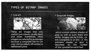
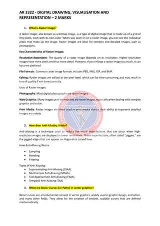
1. What is Raster Image?
A raster image, also known as a bitmap image, is a type of digital image that is made up of a grid of
tiny pixels, each with its own color. When you zoom in on a raster image, you can see the individual
pixels that make up the image. Raster images are ideal for complex and detailed images, such as
photographs.
Key Characteristics of Raster Images:
Resolution-dependent: The quality of a raster image depends on its resolution. Higher resolution
images have more pixels and thus more detail. However, if you enlarge a raster image too much, it can
become pixelated.
File Formats: Common raster image formats include JPEG, PNG, GIF, and BMP.
Editing: Raster images are edited at the pixel level, which can be time-consuming and may result in
loss of quality if not done correctly.
Uses of Raster Images:
Photography: Most digital photographs are raster images.
Web Graphics: Many images used on websites are raster images, especially when dealing with complex
graphics and colors.
Print Media: Raster images are often used in print media due to their ability to represent detailed
images accurately.
2. How does Anti-Aliasing Works?
Anti-aliasing is a technique used to reduce the visual imperfections that can occur when high-
resolution images are displayed in lower resolutions. These imperfections, often called "jaggies," are
the jagged edges that can appear on diagonal or curved lines.
How Anti-Aliasing Works:
• Sampling
• Blending
• Filtering
Types of Anti-Aliasing:
• Supersampling Anti-Aliasing (SSAA)
• Multisample Anti-Aliasing (MSAA)
• Fast Approximate Anti-Aliasing (FXAA)
• Temporal Anti-Aliasing (TAA)
3. What are Bezier Curves (or Paths) in vector graphics?
Bézier curves are a fundamental concept in vector graphics, widely used in graphic design, animation,
and many other fields. They allow for the creation of smooth, scalable curves that are defined
mathematically.
21.
AR 3322 -DIGITAL DRAWING, VISUALISATION AND
REPRESENTATION – 2 MARKS
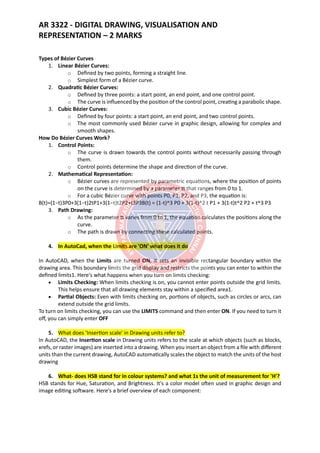
Types of Bézier Curves
1. Linear Bézier Curves:
o Defined by two points, forming a straight line.
o Simplest form of a Bézier curve.
2. Quadratic Bézier Curves:
o Defined by three points: a start point, an end point, and one control point.
o The curve is influenced by the position of the control point, creating a parabolic shape.
3. Cubic Bézier Curves:
o Defined by four points: a start point, an end point, and two control points.
o The most commonly used Bézier curve in graphic design, allowing for complex and
smooth shapes.
How Do Bézier Curves Work?
1. Control Points:
o The curve is drawn towards the control points without necessarily passing through
them.
o Control points determine the shape and direction of the curve.
2. Mathematical Representation:
o Bézier curves are represented by parametric equations, where the position of points
on the curve is determined by a parameter tt that ranges from 0 to 1.
o For a cubic Bézier curve with points P0, P1, P2, and P3, the equation is:
B(t)=(1−t)3P0+3(1−t)2tP1+3(1−t)t2P2+t3P3B(t) = (1-t)^3 P0 + 3(1-t)^2 t P1 + 3(1-t)t^2 P2 + t^3 P3
3. Path Drawing:
o As the parameter tt varies from 0 to 1, the equation calculates the positions along the
curve.
o The path is drawn by connecting these calculated points.
4. In AutoCad, when the Limits are 'ON' what does it do
In AutoCAD, when the Limits are turned ON, it sets an invisible rectangular boundary within the
drawing area. This boundary limits the grid display and restricts the points you can enter to within the
defined limits1. Here's what happens when you turn on limits checking:
• Limits Checking: When limits checking is on, you cannot enter points outside the grid limits.
This helps ensure that all drawing elements stay within a specified area1.
• Partial Objects: Even with limits checking on, portions of objects, such as circles or arcs, can
extend outside the grid limits.
To turn on limits checking, you can use the LIMITS command and then enter ON. If you need to turn it
off, you can simply enter OFF
5. What does 'Insertion scale' in Drawing units refer to?
In AutoCAD, the Insertion scale in Drawing units refers to the scale at which objects (such as blocks,
xrefs, or raster images) are inserted into a drawing. When you insert an object from a file with different
units than the current drawing, AutoCAD automatically scales the object to match the units of the host
drawing
6. What- does HSB stand for in colour systems? and what 1s the unit of measurement for 'H'?
HSB stands for Hue, Saturation, and Brightness. It's a color model often used in graphic design and
image editing software. Here's a brief overview of each component:
22.
AR 3322 -DIGITAL DRAWING, VISUALISATION AND
REPRESENTATION – 2 MARKS
• Hue (H): This represents the type of color (such as red, blue, yellow). It's measured in degrees
on a color wheel, ranging from 0° to 360°. For example, red is at 0°, green is at 120°, and blue
is at 240°.
• Saturation (S): This measures the intensity or purity of the color. It's expressed as a percentage
from 0% (gray) to 100% (full color).
• Brightness (B): This indicates how light or dark the color is. It’s also expressed as a percentage
from 0% (black) to 100% (full brightness).
In the HSB color model, the unit of measurement for Hue (H) is degrees, reflecting its position on the
color wheel.
7. Name three basic types of Boolean operation in 3D modelling?
In 3D modeling, Boolean operations are used to combine or modify shapes by applying mathematical
operations. Here are three basic types of Boolean operations:
1. Union (or Add):
o This operation combines two or more objects into a single object.
o It takes the outer boundaries of all the combined objects, creating a new shape that
encompasses all the original shapes.
2. Difference (or Subtract):
o This operation subtracts one object from another.
o It removes the volume of one shape from another, resulting in a new shape with the
subtracted portion removed.
3. Intersection (or Intersect):
o This operation creates a new shape from the overlapping volume of two or more
objects.
o Only the area where the objects intersect remains, while the rest is discarded.
8. How does a 'Sweep' command work?
The Sweep command in AutoCAD is a powerful tool for creating 3D models by sweeping a 2D profile
along a specified path.
9. What is a UV Mapping?
UV Mapping is a technique used in 3D modeling to map a 2D image texture onto a 3D model. The term
"UV" refers to the coordinates used to map the texture: U and V are the horizontal and vertical axes of
the 2D texture image, respectively, differentiating from the 3D space's X, Y, and Z axes.
How UV Mapping Works:
1. Unwrapping: The process begins by "unwrapping" the 3D model, essentially flattening it out
into a 2D plane. This is similar to unwrapping a present, turning the 3D shape into a flat surface.
2. Assigning Coordinates: Each vertex of the 3D model is assigned corresponding UV coordinates
on the 2D texture. These coordinates dictate how the texture wraps around the 3D model.
3. Applying Texture: The 2D texture is then applied to the 3D model using the UV coordinates.
This allows the texture to conform accurately to the model's surfaces, providing detail and
realism.
Applications of UV Mapping:
• Texturing: Applying detailed textures to models in video games, movies, and animation.
• Detailing: Adding fine details like colors, patterns, and bumps without increasing the polygon
count.
23.
AR 3322 -DIGITAL DRAWING, VISUALISATION AND
REPRESENTATION – 2 MARKS
• Customizing: Allowing for more complex and custom textures to be applied to various parts
of the model.
10. Name the different types of light options available in AutoCad
In AutoCAD, there are three basic types of light options available:
1. Point Light: Emits light in all directions from a single point, like a light bulb.
2. Spotlight: Emits light in a specific direction, creating a focused beam, similar to a flashlight.
3. Distant Light: Simulates sunlight, providing uniform light from a distant source.
These lighting options help enhance the realism and visual clarity of your 3D models.
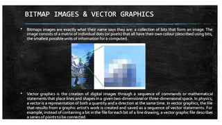
11. Describe the term vector graphics.
Vector graphics are images created using mathematical equations to represent shapes, lines, curves,
and polygons. Unlike raster images, which are made up of individual pixels, vector graphics use
geometric primitives to define the image. This makes vector graphics resolution-independent,
meaning they can be scaled up or down without any loss of quality.
12. What is the benefit of a graphic card?
A graphics card enhances visual experiences by accelerating rendering for gaming, design, and video
editing. It offloads tasks from the CPU, improving overall system performance.
13. Describe dynamic block?
A dynamic block in AutoCAD is a block with custom properties and behaviors that you can modify
through grips or parameter settings, allowing for more flexible and efficient design workflows. It
simplifies drawing modifications and can adapt to various design requirements.
14. Comment on the use of the ortho command
The Ortho command in AutoCAD restricts cursor movement to horizontal or vertical directions,
facilitating precise drafting of orthogonal lines. This is particularly useful for creating accurate
architectural and engineering drawings. It enhances drawing consistency and reduces errors.
15. What are the three Boolean operations
The three Boolean operations in AutoCAD are Union, Subtract, and Intersect. Union combines two or
more objects into one. Subtract removes one set of objects from another, and Intersect creates a new
object from the overlapping areas of the selected objects.
16. What is the meaning of V-Port
In AutoCAD, V-Port refers to a viewport, which is a window or frame within the drawing area that
displays a specific part of the model. Viewports allow users to work on different parts of a drawing at
different scales and can be used in both model space and paper space1. They help manage large
drawings by dividing the display into manageable sections
24.
AR 3322 -DIGITAL DRAWING, VISUALISATION AND
REPRESENTATION – 2 MARKS
17. What is the use of the camera in Sketch up?
In SketchUp, the camera tool allows users to control the viewpoint and perspective, simulating a real-
world camera. This helps create accurate visualizations of 3D models, ensuring the desired angles and
views for presentations and design reviews.
18. What is 3D rendering explain in 2 lines
3D rendering is the process of converting 3D models into 2D images or animations with realistic
lighting, textures, and shading. It's used in various fields like architecture, movies, and video games to
create lifelike visualizations.
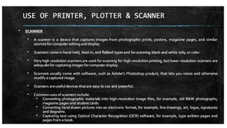
19. List any two uses of the plotter?
Plotters are primarily used for:
1. Large-scale printing: They produce high-quality, detailed large-format graphics, such as
architectural blueprints, engineering designs, and posters.
2. Technical illustrations: Plotters are ideal for creating precise and intricate technical drawings
for various industries, including construction, engineering, and manufacturing.
20. Outline the Polyline Command in Brief
The Polyline command in AutoCAD creates a continuous line composed of one or more line or arc
segments. It allows users to draw complex shapes and paths that are treated as a single object, making
it easier to modify and manipulate the design as a whole. This command is essential for creating
detailed and precise drawings efficiently.
21. Differentiate between a bitmap image and a vector graphics.
Bitmap Image:
• Composition: Made up of individual pixels, each with a specific color value.
• Scaling: Loses quality and becomes pixelated when enlarged.
• File Types: Common formats include JPEG, PNG, and BMP.
• Usage: Ideal for detailed images like photographs.
Vector Graphics:
• Composition: Comprised of paths defined by mathematical equations.
• Scaling: Can be resized infinitely without losing quality.
• File Types: Common formats include SVG, EPS, and PDF.
• Usage: Perfect for logos, icons, and illustrations where clarity at any size is needed.
22. List four tools for editing graphics.
• Adobe Photoshop: Renowned for its advanced features, Photoshop is ideal for photo editing,
retouching, and creating complex digital art.
• CorelDRAW: A versatile tool for vector graphic design, suitable for creating logos, brochures,
and other detailed designs.
• GIMP (GNU Image Manipulation Program): A free and open-source alternative to Photoshop,
great for photo retouching and image composition.
25.
AR 3322 -DIGITAL DRAWING, VISUALISATION AND
REPRESENTATION – 2 MARKS
• Inkscape: Another free tool focused on vector graphics, perfect for creating scalable graphic
designs.
23. What do you understand by "Creating a family" in Building Modelling?
In Building Modelling, creating a family refers to the process of defining a set of related elements with
shared properties and behaviors in a BIM (Building Information Modeling) software like Revit. These
elements, such as windows, doors, or furniture, are grouped into a family to streamline design and
ensure consistency across similar objects2. This approach enhances efficiency and accuracy in
modeling projects.
24. Differentiate between Model space and Paper space.
In AutoCAD, Model Space is where you create and edit your designs in a full, unlimited 3D
environment, while Paper Space is used for layout and plotting, allowing you to arrange different views
and scales of your model for printing on sheets.
25. List the steps invoked in taking a printout to scale.
• Set up the Layout: Switch to Paper Space and create a layout.
• Insert a Viewport: Place and adjust a viewport to show the desired part of your drawing.
• Set the Scale: Select the viewport and specify the desired scale from the properties.
• Print Setup: Use the "Plot" command to configure print settings, ensuring the scale is correct
before printin
26. Create a model showing addition of three cubes.
27. Create a glossy metal ball model.
28. Create an angular wall and demonstrate aligned dimensioning.
29. List the steps invoked in setting a scene.
• Create or Import Models: Start by drawing or importing the 3D models you need.
• Position Objects: Arrange your models in the desired layout for your scene.
• Adjust the Camera: Use the camera tools to set the desired viewpoint and perspective.
• Apply Textures and Materials: Enhance your models with realistic textures and
materials.
• Set Lighting and Shadows: Configure lighting and shadows to bring depth and realism
to the scene.
30. What are the important consideration to be taken into account while setting the camera for a
3D Visual?
• Field of View (FOV): Adjust the camera's angle to ensure it captures the desired area without
distortion.
• Camera Angle and Position: Choose angles and positions that best represent the scene,
highlight key elements, and create an interesting composition.
• Depth of Field: Control the focus range to emphasize certain parts of the scene while blurring
out the background, adding a sense of depth.
26.
AR 3322 -DIGITAL DRAWING, VISUALISATION AND
REPRESENTATION – 2 MARKS
• Lighting: Ensure that the lighting complements the camera setup, highlighting the important
features without causing unwanted shadows or glare.
• Perspective and Scale: Use perspective settings to maintain the correct proportions and spatial
relationships in the scene.
• Motion and Path: If animating the camera, plan smooth movements and transitions to create
a natural and engaging viewer experience.
31. Define the term Pixel
A pixel is the smallest unit of a digital image or display, representing a single point of color. Pixels are
the tiny dots that collectively form the images you see on screens, with each pixel's color and
brightness contributing to the overall picture quality.
32. In AutoCAD, what is the command to edit Polyline?
In AutoCAD, the command to edit a polyline is PEDIT (short for Polyline Edit). You can access it by
typing PEDIT in the command line or by selecting the "Edit Polyline" button from the Home tab's
Modify panel.
33. List the differences between printer and plotter
Printers are designed for standard-sized text and images using inkjet or laser technology, while plotters
produce large-format, precise line drawings ideal for technical and engineering designs. Plotters excel
in detailed and large-scale graphics, whereas printers are suited for everyday documents.
34. What are the two forms of text entry in AutoCAD?
In AutoCAD, the two forms of text entry are Single-line Text (TEXT) and Multi-line Text
(MTEXT).
1. Single-line Text (TEXT): Used for creating simple, single-line annotations.
2. Multi-line Text (MTEXT): Allows for more complex, formatted text blocks with multiple lines
and advanced formatting options.
35. What is the difference between 'copy' and 'offset' command?
In AutoCAD, the Copy command creates duplicates of selected objects, allowing you to place
them anywhere within the drawing. The Offset command, on the other hand, creates a parallel
duplicate of the selected object at a specified distance, ideal for creating concentric shapes or
parallel lines.
36. What are complimentary colours?
Complementary colors are pairs of colors that, when combined, cancel each other out, resulting in a
grayscale color like white or black. On the color wheel, they are directly opposite each other. For
example, red and green, blue and orange, and yellow and purple are complementary colors. When
27.
AR 3322 -DIGITAL DRAWING, VISUALISATION AND
REPRESENTATION – 2 MARKS
placed next to each other, they create a high contrast and vibrant look, enhancing each other's
intensity.
37. In AutoCAD, define 'array' and it's types?
In AutoCAD, an array is a command that creates multiple copies of selected objects in a
specified pattern. There are three types of arrays:
1. Rectangular Array: Copies objects in a grid pattern defined by rows and columns.
2. Polar Array: Copies objects in a circular pattern around a specified center point.
3. Path Array: Copies objects along a specified path, such as a line, arc, or polyline.
38. List two 3D Primitives.
Two common 3D primitives in AutoCAD are:
1. Box: Creates a simple rectangular cuboid by defining its length, width, and height.
2. Cylinder: Creates a cylindrical shape by specifying its base radius and height.
39. What is a 'wire frame' in 3D modelling?
A wireframe in 3D modeling is a visual representation of a 3D object using lines and vertices
to depict its edges and structure. It shows the skeleton-like outline of the model without any
surfaces, textures, or shading. Wireframes are used for designing, visualizing, and refining the
geometric structure of a model.
40. List two 3D rendering softwares.
Two widely used 3D rendering software are:
1. V-Ray: Known for its high-quality rendering capabilities, it integrates with various 3D modeling
tools like SketchUp and 3ds Max.
2. Blender: A free and open-source software that offers powerful rendering options, including
real-time rendering and advanced features for creating professional-quality visuals.
28.
DIGITAL DRAWING, VISUALIZATIONAND REPRESENTATION
UNIT I – Introduction to computer and Image editing
1. Define hardware and software with examples.
Hardware is the physical part of a computer (e.g., monitor, keyboard). Software is a set of
instructions that tells the hardware what to do (e.g., AutoCAD, Photoshop).
2. What is the difference between input devices and output devices?
Input devices send data to the computer (e.g., mouse, scanner), output devices display results
from the computer (e.g., printer, monitor).
3. Name two types of computer memory and give their functions.
RAM – Temporary storage for active processes.
ROM – Permanent storage for essential startup instructions.
4. What is an operating system? Give one example.
Software that manages hardware and software resources. Example: Windows 11.
5. Define GUI (Graphical User Interface).
A user interface that uses icons, windows, and menus instead of text commands.
6. Mention two advantages of using computers in design.
Speeds up the design process, improves accuracy in drawings.
7. What is CAD? Expand the term.
CAD – Computer-Aided Design, used for creating precise drawings and models.
8. Name two commonly used architectural design software.
AutoCAD, SketchUp.
9. Define vector graphics and raster graphics.
Vector graphics are made of lines and shapes, scalable without losing quality. Raster graphics
are made of pixels that can lose quality when enlarged.
29.
10. What isa file extension? Give an example.
The suffix in a filename indicating file type, e.g., .jpg, .dwg.
11. Define image resolution.
The amount of detail in an image, measured in pixels (width × height).
12. What is the difference between pixels and DPI?
Pixels are the smallest elements of an image. DPI (dots per inch) is the print resolution.
13. Name two image file formats and their uses.
JPEG – for compressed photos; PNG – for high-quality images with transparency.
14. What is cropping in image editing?
Removing unwanted outer areas of an image.
15. Define layer in Photoshop.
A separate level on which images, text, or effects can be placed without affecting other
elements.
16. What is the function of the magic wand tool?
Selects areas of similar colour in an image automatically.
17. Mention two uses of image editing in architecture.
Enhancing presentation images, creating photomontages of proposed designs.
18. What is the difference between “save” and “save as”?
“Save” updates the existing file, “Save As” creates a new file with changes.
19. Define RGB and CMYK color modes.
RGB – Red, Green, Blue (used for screens). CMYK – Cyan, Magenta, Yellow, Black (used for
printing).
20. What is the purpose of the clone stamp tool?
To copy pixels from one area of an image to another to remove imperfections
30.
21. Name twocommon keyboard shortcuts for image editing.
Ctrl + Z – Undo; Ctrl + T – Transform.
22. What is the purpose of using layers and masks together?
Allows non-destructive editing and precise control over which parts of a layer are visible.
23. Differentiate between bitmap images and vector images.
Bitmap – made of pixels, fixed resolution. Vector – made of paths, scalable without quality loss.
24. Name two common input devices for image editing.
Graphics tablet, scanner.
25. What is a PSD file?
Photoshop Document format that supports layers and editing.
26. Name two image editing software other than Photoshop.
GIMP, CorelDRAW.
27. What is the difference between JPEG and PNG formats?
JPEG – compressed, smaller size, no transparency. PNG – lossless, supports transparency.
UNIT II – Basic Fundamental Building Modelling and Viewing the Building Model
1. What is AutoCAD?
A computer-aided design (CAD) software used to create precise 2D drawings and 3D models.
2. What is the function of the ARC command?
Creates a curved line segment between points.
3. What is the MIRROR command?
Creates a reversed copy of an object.
31.
UNIT III –Introduction to 3D Modelling
1. Name two common software used for building modelling.
SketchUp, Revit.
2. Define wireframe model.
A 3D model that shows only the edges and outlines of objects without surfaces.
3. What is the difference between orthographic and perspective views?
Orthographic – shows objects without perspective distortion;
Perspective – shows objects with depth perception.
4. Define extrusion in 3D modelling.
Extending a 2D shape into 3D space to create a solid object.
5. What is the orbit tool used for?
To rotate the view around the 3D model.
6. Define walk-through in 3D software.
A simulation that allows movement inside a model as if walking through it.
7. What is a scene in 3D modelling software?
A saved camera view for quick navigation or presentation.
8. What is the difference between parallel projection and perspective projection?
Parallel – objects remain the same size regardless of distance;
Perspective – distant objects appear smaller.
9. What is snapping in modelling software?
A feature that locks movement or drawing to specific points or alignments.
10. Name two common file formats for exporting 3D models.
.skp, .obj.
32.
11. What isa walkthrough animation?
A video generated by moving through saved scenes of the model.
12. What is the difference between a model space and a layout space?
Model space – 3D modelling area;
Layout space – presentation sheets with scaled views.
13. What is geolocation in building modelling?
Placing the model in a real-world location for accurate sunlight and shadow studies.
UNIT IV – Introduction to 3D Modelling
1. What is ray tracing?
A rendering technique that simulates the path of light for realistic lighting and shadows.
2. Name two types of texture maps.
Diffuse map, Bump map.
3. What is HDRI lighting?
High Dynamic Range Image used as a light source to produce realistic lighting and reflections.
4. Name two common image formats for rendered outputs.
PNG, JPEG.
5. What is the difference between rendering and modelling?
Modelling is creating the 3D geometry; rendering is producing a visual image from that
geometry.
6. Name any two commonly used rendering software.
V-Ray, Lumion.
33.
AUTOCAD SHORTCUTS FORDRAFTSMAN
Basic Drawing Commands
1 L – Line
2 PL – Polyline
3 REC – Rectangle
4 C – Circle
5 A – Arc
6 EL – Ellipse
7 POL – Polygon
Modify Commands
1 O – Offset
2 TR – Trim
3 EX – Extend
4 M – Move
5 CO – Copy
6 RO – Rotate
7 MI – Mirror
8 S – Stretch
9 SC – Scale
10 F – Fillet
11 CHA – Chamfer
12 X – Explode
13 J – Join
Drafting Accuracy
1 F3 – Object Snap
2 F8 – Ortho Mode
3 F10 – Polar Tracking
4 F9 – Snap Mode
5 OS – Object Snap Settings
6 UN – Units
Layers & Properties
1 LA – Layer Manager
2 LAYISO – Isolate Layer
3 LAYOFF – Layer Off
4 LAYON – Layer On
5 PR – Properties
6 MA – Match Properties
Blocks
1 B – Create Block
2 I – Insert Block
3 WBLOCK – Write Block
34.
4 BC –Block Editor
Text & Dimensioning
1 T – Single Line Text
2 MT – Multiline Text
3 D – Dimension Style
4 DIM – Dimension
5 DIMLINEAR – Linear Dimension
6 DIMCONTINUE – Continue Dimension
Hatch & Area
1 H – Hatch
2 BO – Boundary
3 AREA – Area Calculation
View & Navigation
1 Z – Zoom
2 Z E – Zoom Extents
3 P – Pan
4 RE – Regen
File & Plotting
1 CTRL+S – Save
2 CTRL+O – Open
3 CTRL+P – Plot
4 PLOT – Print
5 EXPORTPDF – Save as PDF
Draftsman Tips
1 Always draw using Layers
2 Use Offset + Trim for wall drawings
3 Keep Blocks for repeated elements
4 Check Units & Scale before plotting
5 Use Monochrome.ctb for site drawings
35.
How to SaveAutoCAD Drawing as PDF
Method 1: Using PLOT Command
1 Type PLOT and press Enter.
2 Select printer as DWG To PDF.pc3.
3 Choose required paper size (A4 / A3 / A1 / A0).
4 Select Plot Area: Layout or Window.
5 Set drawing scale (1:50, 1:100, etc.).
6 Choose plot style: monochrome.ctb or acad.ctb.
7 Preview and click OK.
8 Choose location and save the PDF.
Method 2: Quick Export
1 Type EXPORTPDF.
2 Press Enter.
3 Choose location and save.
Recommended Settings for Architecture Drawings
1 Use monochrome.ctb for black & white drawings.
2 Turn ON lineweights.
3 Use layout tabs for final printing.
4 Check scale carefully before saving.