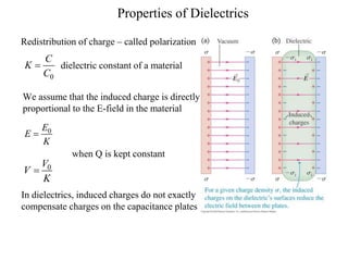
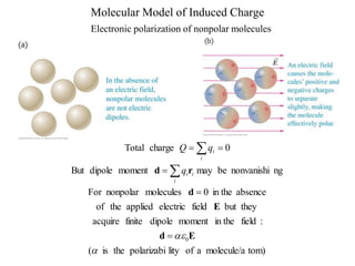
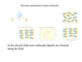
1) Dielectrics increase the capacitance of a capacitor by introducing polarizable molecules between the plates that can be oriented by an applied electric field. This leads to an increased charge storage capacity and a lower operating voltage.
2) The dielectric constant is a property of the material that quantifies its ability to increase capacitance. It is defined as the ratio of the capacitance with a dielectric to the capacitance without.
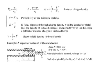
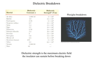
3) Dielectrics break down at a certain maximum electric field strength, above which the material can no longer maintain its insulating properties and will conduct electricity between the plates.


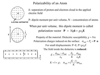
![Field inside the capacitor became smaller – why?
There are polarization (induced)
charges
– Dielectrics get polarized
We know what happens to the conductor in the electric field
Field inside the conductor E=0
outside field did not change
Potential difference (which is the
integral of field) is, however, smaller.
( )
o
V d b
0
[1 / ]
A
C
d b d
](https://image.slidesharecdn.com/varun-230801102357-9e444585/85/Dielectric-constant-by-varun-s-22ECR224-pptx-8-320.jpg)


![Dielectric properties[read only]](https://cdn.slidesharecdn.com/ss_thumbnails/dielectricpropertiesread-only-220208052225-thumbnail.jpg?width=640&height=640&fit=bounds)


