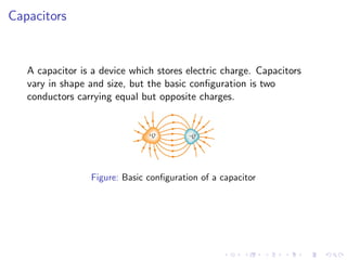
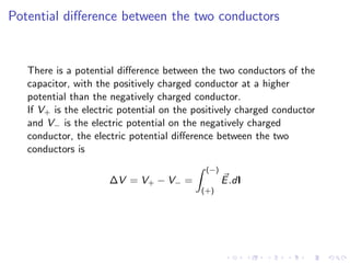
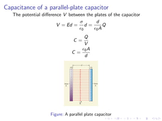
- A capacitor is a device that stores electric charge and consists of two conductors carrying equal but opposite charges. There is a potential difference between the conductors.
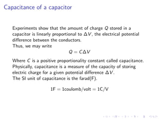
- The amount of charge Q stored in a capacitor is proportional to the potential difference ΔV between the conductors. The constant of proportionality is called the capacitance C.
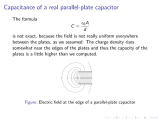
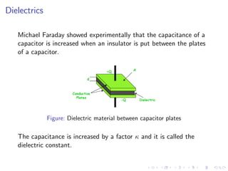
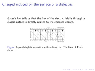
- Inserting a dielectric material between the capacitor plates increases the capacitance by a factor called the dielectric constant. Within the dielectric, the electric field is reduced even though the surface charges remain the same.


![ANIMAL_CELL_,_TISSUE_AND_ORGAN_CULTURE[1].pptx](https://cdn.slidesharecdn.com/ss_thumbnails/animalcelltissueandorganculture1-260204172026-4462b440-thumbnail.jpg?width=640&height=640&fit=bounds)


