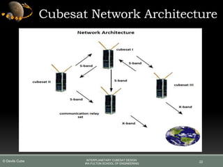
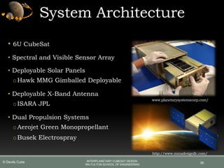
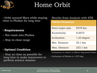
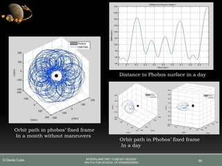
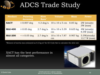
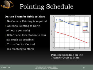
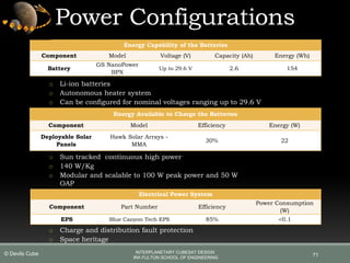
This document outlines a proposed CubeSat mission to study Phobos, one of Mars' moons. A network of 4 CubeSats would work together to overcome limitations of a single CubeSat. Two CubeSats would each carry a spectrometer and camera to analyze surface composition and image Phobos. A third CubeSat would carry an X-ray spectrometer. The fourth CubeSat would function as a communications relay between the network and Earth. This coordinated approach would allow for more comprehensive scientific analysis of Phobos compared to previous single-satellite missions.

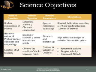

![Spectrometer
10
Spectrometer
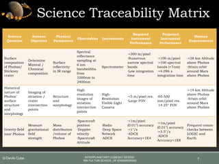
Parameter
Edmond Optics
1000 2000nm
InGaAs NIR
NIR Quest 256-
2.5
Argus 1000
Mass [g] 650 1180 230
Volume [cc] 1020.6 940.7 180
Power [W] 12 15 6.2
Range [nm] 1000 - 2000 900 - 2500 1000 - 2400
Spectral Resolution
[nm]
8 9.5 12
No of bands 128 128 100
No of pixels 256 Pixel Array 256 Pixel Array 256 Pixel Array
Integration Time 20 µs to 10 s 1-400 ms 0.5µs to 4.1s
INTERPLANETARY CUBESAT DESIGN
IRA FULTON SCHOOL OF ENGINEERING
© Devils Cube](https://image.slidesharecdn.com/2e61c247-5ace-4cea-8456-0bfab0f5026d-151222055707/85/Devils-Logic-PDR-presentation-10-320.jpg)
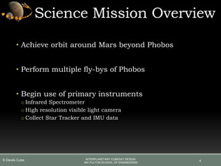
![11
0
0.5
1
1.5
2
2.5
3
3.5
4
4.5
EDMOND OPTICS NIR QUEST ARGUS 1000
Edmond Optics NIR Quest Argus 1000
Power consumption[Whr] 3 3.75 1.55
Data per exposure[kb] 4.096 4.096 3.328
Spectrometer Power Consumption & Data Generation
Power consumption[Whr] Data per exposure[kb]
Spectrometer
INTERPLANETARY CUBESAT DESIGN
IRA FULTON SCHOOL OF ENGINEERING
© Devils Cube](https://image.slidesharecdn.com/2e61c247-5ace-4cea-8456-0bfab0f5026d-151222055707/85/Devils-Logic-PDR-presentation-11-320.jpg)
![Visual Spectrum Camera
12
Cameras
Parameters
CIRES - E2V Malin ECAM-C50
Teledyne Dalsa
Genie
Mass [g]
Sensor system 70 256 196
Lens system 240 100 460
Volume [cc]
Sensor system 50.92 199.1 129.7
Lens system 103.5 269.7 367.2
Power [W] 1.5 2.5 4.5
Pixel Density [MP] 1.3 5 12
Fly-by
SR [m/pixel] 1.8 1.8 1.8
Max WD [m] 6912.00 14310.00 22118.40
Nom Case
SR [m/pixel] 2083.33 1006.29 651.04
WD [m] 8000.00 8000.00 8000.00
Best Case
SR [m/pixel] 1302.08 628.93 406.90
WD [m] 5000.00 5000.00 5000.00
WD: Working distance SR: Spatial resolution
INTERPLANETARY CUBESAT DESIGN
IRA FULTON SCHOOL OF ENGINEERING
© Devils Cube](https://image.slidesharecdn.com/2e61c247-5ace-4cea-8456-0bfab0f5026d-151222055707/85/Devils-Logic-PDR-presentation-12-320.jpg)
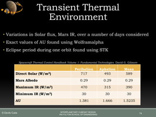
![13
0
5
10
15
20
25
30
35
40
CIRES - E2V MALIN ECAM-C50 TELEDYNE DALSA GENIE
CIRES - E2V Malin ECAM-C50 Teledyne Dalsa Genie
Power Consumption[Whr] 0.375 0.625 2.375
size of single image[MB] 3.75 14.74 36
Camera Power Generation and Data Generation
Power Consumption[Whr] size of single image[MB]
Visual Spectrum Camera
INTERPLANETARY CUBESAT DESIGN
IRA FULTON SCHOOL OF ENGINEERING
© Devils Cube](https://image.slidesharecdn.com/2e61c247-5ace-4cea-8456-0bfab0f5026d-151222055707/85/Devils-Logic-PDR-presentation-13-320.jpg)
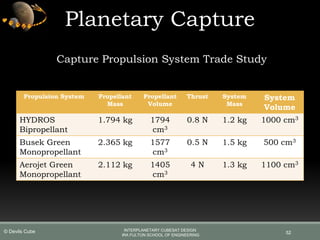
![Budgets / Feasibility
Mass, Volume and Power Budget
Subsystem
Mass [kg]
(Max 14)
Volume [cc]
(Max 7000)
Power [W]
(Max Capture 44)
Chassis 1.000 7000
Power 2.110 700 0.7
Communication 2.440 508 12.9
ADCS 0.850 500 3.0
Propulsion 3.897 3080 15.0
Payload 0.586 591 2.65
Thermal 0.061 60 0.5
Total / Margin 10.944 / 21.8% 5439 / 32.0% 34.75 / 22.8%
30
INTERPLANETARY CUBESAT DESIGN
IRA FULTON SCHOOL OF ENGINEERING
© Devils Cube](https://image.slidesharecdn.com/2e61c247-5ace-4cea-8456-0bfab0f5026d-151222055707/85/Devils-Logic-PDR-presentation-30-320.jpg)


![999 cash[2]](https://cdn.slidesharecdn.com/ss_thumbnails/lzsrjzmzqu2g6ytran2g-signature-3e49a9720aafd161ec5213fc5cb0fac76e0a38578f2089fb876ad1cc6de4bad4-poli-140825181335-phpapp02-thumbnail.jpg?width=640&height=640&fit=bounds)


