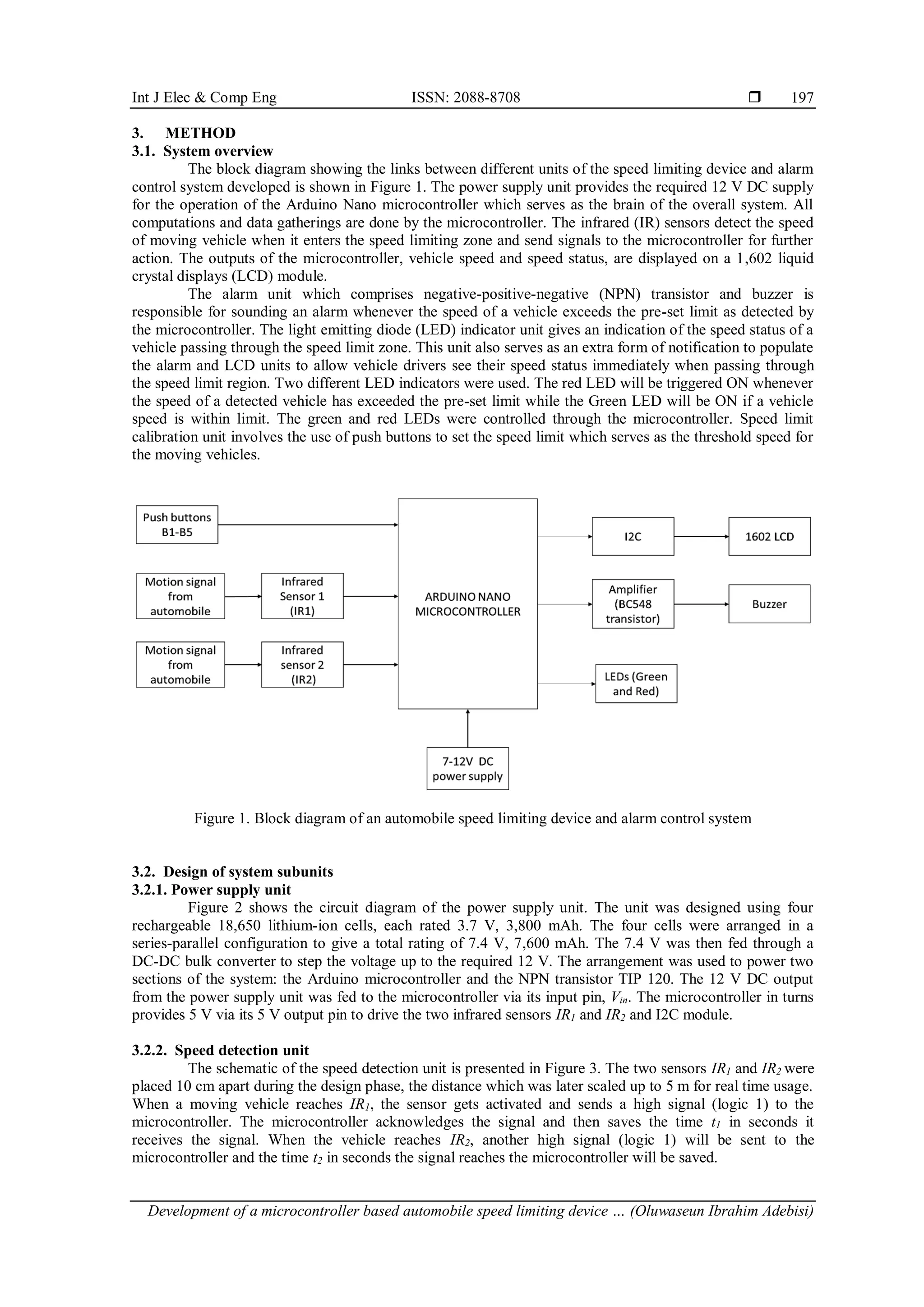
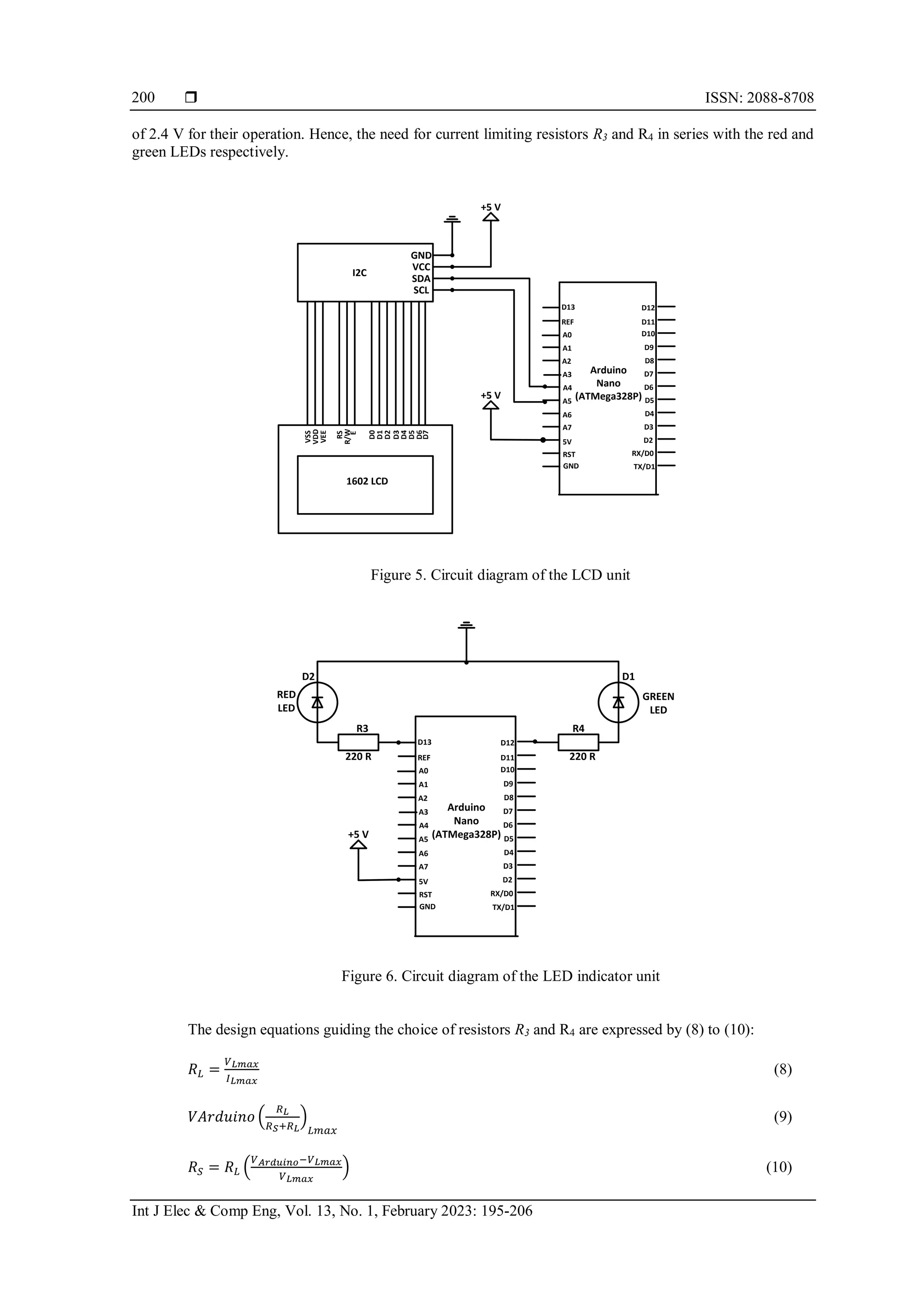
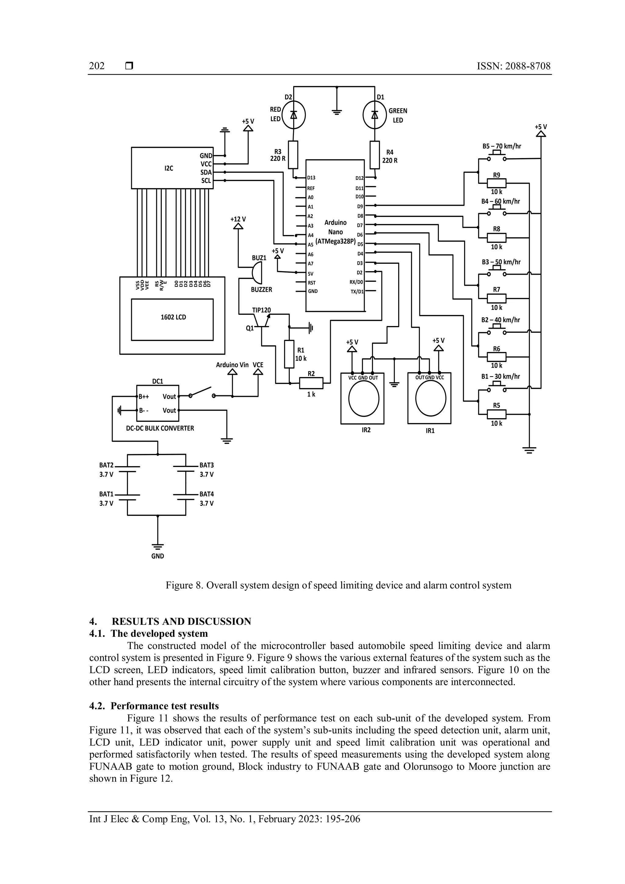
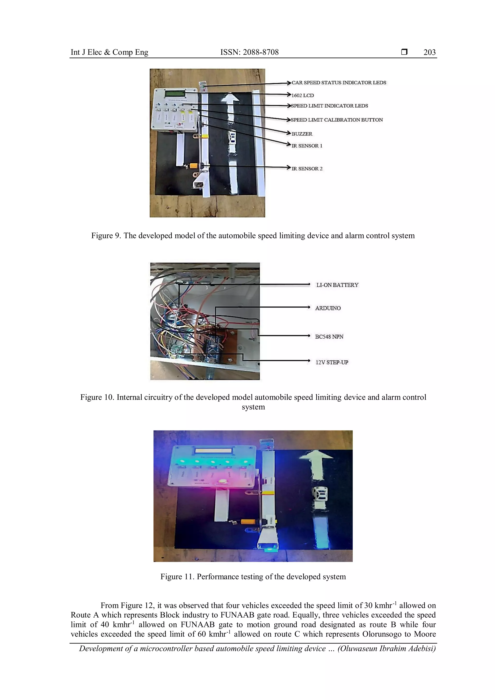
The document describes the development of a microcontroller-based automobile speed limiting device and alarm control system. The system uses Arduino Nano microcontroller, infrared sensors, LCD display, LED indicators, buzzer, and push buttons. The infrared sensors detect vehicle speed and send signals to the microcontroller. The microcontroller then compares the speed to a preset limit and triggers the alarm and LED indicators if the limit is exceeded. The system was tested and found to function satisfactorily with a reading error of 5.83%. The speed limiting device could help reduce accidents from overspeeding.
![International Journal of Electrical and Computer Engineering (IJECE)
Vol. 13, No. 1, February 2023, pp. 195~206
ISSN: 2088-8708, DOI: 10.11591/ijece.v13i1.pp195-206 195
Journal homepage: http://ijece.iaescore.com
Development of a microcontroller based automobile speed
limiting device and alarm control system
Oluwaseun Ibrahim Adebisi1
, Isaiah Adediji Adejumobi1
, Folasade Olayinka Durodola2
,
Haastrup Ayobami Jim1
1
Department of Electrical and Electronics Engineering, Federal University of Agriculture, Abeokuta, Ogun State, Nigeria
2
Department of Mechatronics Engineering, Federal University of Agriculture, Abeokuta, Ogun State, Nigeria
Article Info ABSTRACT
Article history:
Received Oct 8, 2021
Revised Aug 7, 2022
Accepted Aug 16, 2022
Road accident due to overspeeding is a common occurrence in a developing
nation such as Nigeria. Therefore, the need for a device capable of notifying
a vehicle driver when the allowed speed limit of an area is exceeded arises.
In this work, a microcontroller based automobile speed limiting device and
alarm control system was designed and developed. The core components
employed for the system design include Arduino Nano microcontroller, 1602
liquid crystal displays (LCD) module, light-emitting diodes (LEDs), buzzer,
18650 battery, I2C, infrared detectors and push buttons. Data gathering and
circuit designs were implemented with microcontroller as focal point using
suitable design models. Performance test was carried out on the developed
system and the device’s reading error was determined. The developed
automobile speed limiting device and alarm control system was functional
and performed satisfactorily during testing. The reading error of the device
was evaluated as 5.83%. The developed speed limiting device, apart from
being suitable and efficient for vehicle speed measurement, could also be
deployed for general applications requiring speed measurement.
Keywords:
Automobile
Nigeria
Overspeeding
Road accident
Speed limit
This is an open access article under the CC BY-SA license.
Corresponding Author:
Oluwaseun Ibrahim Adebisi
Department of Electrical and Electronics Engineering, College of Engineering, Federal University of
Agriculture
Abeokuta, PMB 2240, Ogun State, Nigeria
Email: adebisioluwaseun@funaab.edu.ng
1. INTRODUCTION
In recent years, society and people have profited enormously from rapidly improving road systems.
At the same time, automobile industry has manufactured and sold mechanized vehicles capable of operating
at extremely high velocities. High-speed travel of an automobile can prompt more mobility and less time to
be spent on a journey [1]–[3]. However, high vehicle speeds have unfavorable impacts, primarily regarding
road accidents and subsequent deaths, injuries and material damage in addition to environmental hazards
created such as noise and fumes discharge from exhausts of the vehicles.
Greater utilization of automobiles can adversely affect the way of life and human well-being, for
instance, the cardiovascular well-being of the community [4]. Individuals living in main metropolitan areas
begin to pine for lower speeds of automobiles on their roads and there is a developing interest to protect the
environment, provide a better quality of life for the populace living in the area, and likewise to guarantee the
well-being of those living close to the streets: pedestrians, bicyclists, children, and individuals with decreased
mobility [5].
There are definite rules and regulations laid out by authorities about driving automobiles on roads,
and these are specific to different countries. These rules also differ on various roads ranging from federal to](https://image.slidesharecdn.com/v1926100emr7aug228oct21k-221118061220-61c01324/75/Development-of-a-microcontroller-based-automobile-speed-limiting-device-and-alarm-control-system-1-2048.jpg)
![ ISSN: 2088-8708
Int J Elec & Comp Eng, Vol. 13, No. 1, February 2023: 195-206
196
state roads. The most common rule in any country is the speed limit on certain roads where a driver of an
automobile will be in violation of the law if the speed of his automobile exceeds the allowed limit on that
particular road being plied [6], [7]. Speed limits are one important approach to accomplish appropriate speeds
[8], [9]. In a speed management conference organized by the European Conference of Ministers Transport
[5] in 2006, it was discussed that speed limits in most urban areas should not exceed 50 km/hr with 30 km/hr
zones promoted in areas where vulnerable road users are especially in danger. Researches have shown that
the speed limits in addition to traffic calming measures are extremely effective at decreasing accidents,
including injuries, with decreases of up to 66% having been illustrated by implementing the speed limit rule
[10].
Globally, around 1.35 million people meet their death annually due to road accidents with an
additional 50 million individuals harmed from road traffic crashes [11]–[15]. While the reason for crashes is
dependent on quite a number of factors, it is by and large agreed that speed limit infringement and
inappropriate speed are the greatest contributors of incidents of road traffic trashes and their severity [16],
[17]–[19]. Although all highways have signboards indicating maximum speed limit for the sake of both
driver’s safety and that of the pedestrian, still drivers disobey highway speed limit [20]–[22]. The driving
behavior of drivers depends on three key indicators including the average speed, the difference with the
speed limits and the accelerator stroke [23], [24]. An increase in the speed of an automobile leads to the
increased distance of movement during the driver’s response time with the halting distance, consequently
increasing the danger from any driver’s error. Despite the gigantic proof of the connection between speed and
crash risk and severity, the conduct keeps on being unavoidable among drivers across the world [25].
Therefore, in view of the inherent dangers of vehicles overspeed on roads, this work aims at developing an
automobile speed limiting device incorporating an alarm control system that can assist in signaling a driver
when the allowed speed limit on a particular road being plied is violated.
2. AUTOMOBILE SPEED LIMITING DEVICE AND CONTROL SYSTEM
The automobile speed limiting device and control system is a speed limit control system that
involves a road monitoring and speed limit control in the vehicle which receives signals from the installed
transmitter by the roadside. The device can automatically reduce the speed of cars and restrain all vehicles
equipped with the said speed limit control system to the various stipulated and posted maximum speed limits
[25]. Some of the potential benefits associated with the use of automobile speed limiting device and control
system include greater time to recognize hazards, reduced distance travelled while reacting to hazards,
reduced halting distance of the vehicle after application of the brake, increased ability of other road users to
determine vehicle speed and time before collision, increased ability of the driver to maintain control of the
vehicle among others.
According to literature, series of studies have been carried out with respect to the development of an
automobile speed limiting device and control system with different technologies employed. Kodali and
Sairam [26] presented design and implementation of a global positioning system (GPS) based car speed
limiting device. The device could determine vehicle’s current location and the maximum allowed speed in
the area of the road being plied. Enokela and Agbo [27] developed a microcontroller based car speed
controller for automatic control of vehicle’s speed within limit stipulated for a particular zone by a regulating
body such as the federal road safety commission (FRSC) in Nigeria. The system was able to compare the pre-
set speed limits with the actual speed that is derived from the speedometer of car for effective speed control.
Khondaker and Kattan [28] designed an algorithm called the variable speed limit control algorithm which
simultaneously maximizes the mobility, safety and environmental benefits in a connected vehicle
environment. Mishra et al. [29] designed a radio frequency (RF) based speed control system for vehicles to
alert drivers in places where the highway department has placed the speed limit signboards. Olei and Polak
[30] worked on an intelligent speed adaptation system which has the capability of notifying drivers of the
speed limit of each road section.
Going by the literature, the previous models require part, if not all, of the device to be placed in
people’s car. The implication is that these systems will cost a whole lot of money to be implemented by the
government of a country. It also means the drivers can easily tamper with the device in their cars either by
adjusting the speedometer setting to give false readings, blocking the device from RF or even removing their
car’s GPS system since it is well known that not all cars have GPS systems. Therefore, the car speed limiting
system developed in this work seeks to get rid of the two major shortcomings of the past models which are
high cost and inherent ease of manipulation by the vehicle drivers.](https://image.slidesharecdn.com/v1926100emr7aug228oct21k-221118061220-61c01324/75/Development-of-a-microcontroller-based-automobile-speed-limiting-device-and-alarm-control-system-2-2048.jpg)
![ ISSN: 2088-8708
Int J Elec & Comp Eng, Vol. 13, No. 1, February 2023: 195-206
198
B++
B- -
Vout
Vout
Arduino Vin VCE
GND
BAT1
3.7 V
BAT2
3.7 V
BAT3
3.7 V
BAT4
3.7 V
DC-DC BULK CONVERTER
DC1
Figure 2. Circuit diagram of the power supply unit
REF
A0
A1
A2
A3
A4
A5
GND TX/D1
RX/D0
D2
D3
D4
D5
D6
D7
D8
D9
Arduino
Nano
(ATMega328P)
D13
A6
A7
5V
D12
D11
D10
RST
IR1
VCC
OUT
GND
IR2
VCC
OUT
GND
+5 V
+5 V
+5 V
Figure 3. Schematic of the speed detection unit
Using the scaled distance of 5 m and the time interval Δt between IR1 and IR2, the speed S in ms-1
at
which the vehicle travels from IR1 to IR2 was estimated from (1) and converted to kmhr-1
using (2):
𝑆 =
𝑑
𝛥𝑡
=
𝑑
𝑡2−𝑡1
(1)
where d is the distance in meters between infrared sensors IR1 and IR2,
𝑆𝑘𝑚ℎ𝑟−1 = 3.6𝑆 (2)
where 𝑆𝑘𝑚ℎ𝑟−1 is the speed travelled in kmhr-1
between the two sensors. Once the speed of the vehicle is
obtained, the microcontroller compares the speed with the pre-set speed limits ranging from 30 to 70 kmhr-1
.
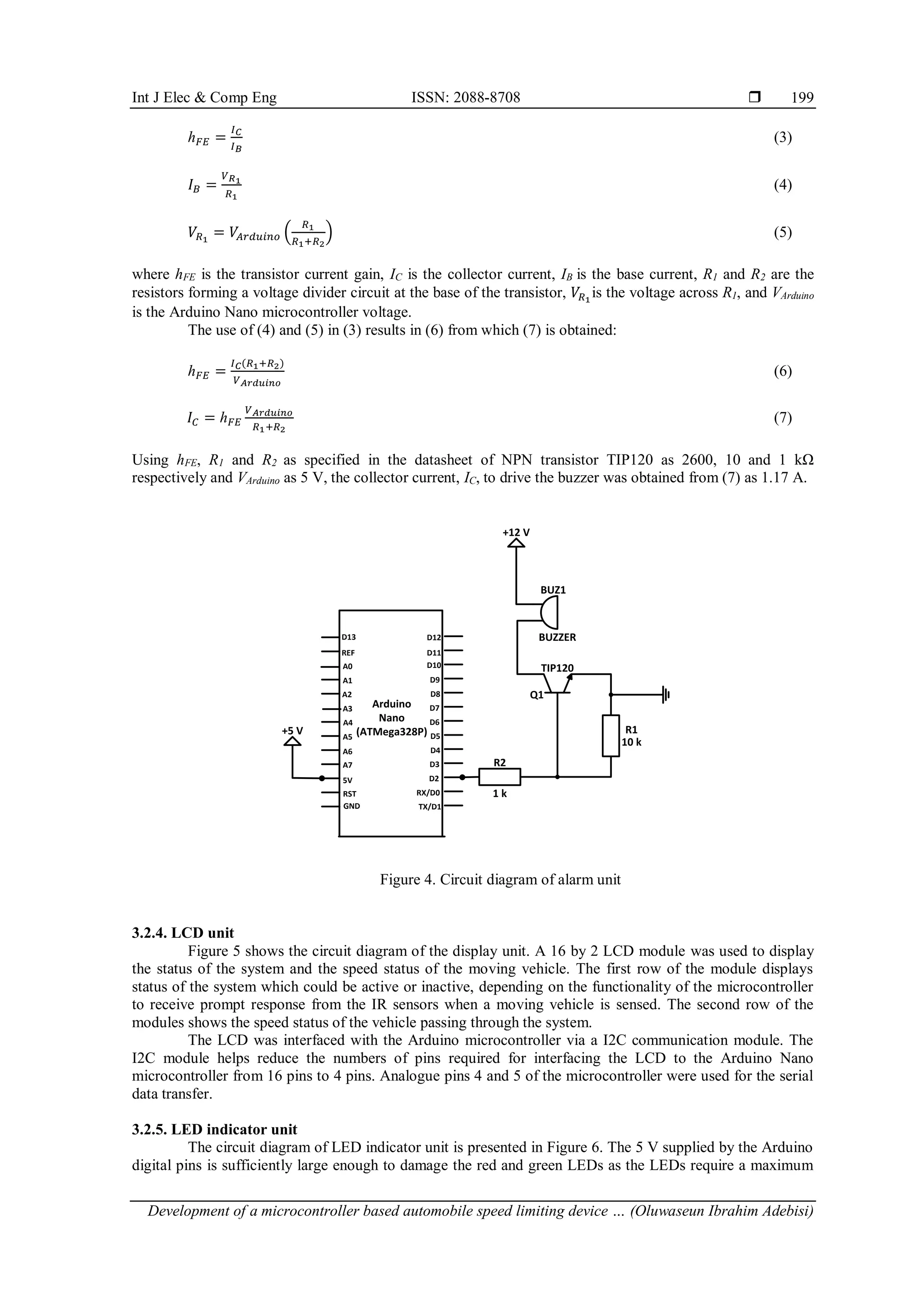
3.2.3. Alarm unit
The circuit diagram of the alarm unit is shown in Figure 4. The NPN transistor TIP120 is used for
amplifying the low power signal (5 V, 40 mA) from the digital pin 2 of the Arduino Nano microcontroller to
trigger the buzzer with power rating of (12 V, 330 mA). The model equations guiding the selection of
resistors R1 and R2 in the circuit of Figure 4 are expressed by (3) to 5 [31]:](https://image.slidesharecdn.com/v1926100emr7aug228oct21k-221118061220-61c01324/75/Development-of-a-microcontroller-based-automobile-speed-limiting-device-and-alarm-control-system-4-2048.jpg)

![ ISSN: 2088-8708
Int J Elec & Comp Eng, Vol. 13, No. 1, February 2023: 195-206
204
junction road. For each of the overspeeding conditions recorded during testing, the system’s buzzer gave a
warning sound. Moreover, comparison of the measured speed with the theoretical estimated speed of the
considered 30 vehicles along the three selected routes revealed that the developed system has an absolute
error of ±5.83%, indicating that the developed system is suitable for speed measurement applications.
Figure 12. Speed measurement using the developed system on three different routes
5. CONCLUSION
Globally, negative impacts of road accidents with the associated deaths, injuries, material damage
among others resulting from vehicle’s speed exceeding the allowed speed limit on any route call for great
concern. This work designed and implemented a microcontroller-based automobile speed limiting device and
alarm control system. The device is capable of alerting a vehicle’s driver the speed status on any road being
plied, provided the acceptable speed limit on such road has been pre-set on the system. In addition to being
cost effective, the developed system is simple and robust. The device can be deployed for use in different
locations with different speed limits. In terms of ruggedness, the device has been tested and proven to
withstand extreme weather conditions like heavy rain, extremely high temperature, vibrations, and noise.
Hence, functionality during harsh weather conditions can be guaranteed. The system is, however, only
equipped with an alarm and indicator LEDs to identify over speeding vehicles. As a result, there is still a
need for traffic officials to be present at speed limit regions as the device can only help identify an over
speeding vehicle and then notify the officials in order to take necessary actions. To improve system, it is
recommended that technologies like machine vision be integrated to the system. The implementation of
machine vision will enable the device to easily capture information of over speeding vehicles such as car
plate number, face of driver, car model and color and then sent to the authorized personnel for further
actions.
ACKNOWLEDGEMENT
The authors are grateful to HIC Mikrolab, Asero-Abeokuta, Ogun State, Nigeria for the immense
assistance rendered during the implementation stage of the developed system.
REFERENCE
[1] E. F. Grumert and A. Tapani, “Using connected vehicles in a variable speed limit system,” Transportation Research Procedia,
vol. 27, pp. 85–92, 2017, doi: 10.1016/j.trpro.2017.12.050.
[2] M. Tanishita and B. van Wee, “Impact of vehicle speeds and changes in mean speeds on per vehicle-kilometer traffic accident
rates in Japan,” IATSS Research, vol. 41, no. 3, pp. 107–112, Oct. 2017, doi: 10.1016/j.iatssr.2016.09.003.
[3] J.-B. Sheu and H.-J. Wu, “Driver perception uncertainty in perceived relative speed and reaction time in car following-A quantum
optical flow perspective,” Transportation Research Part B: Methodological, vol. 80, pp. 257–274, Oct. 2015, doi:
10.1016/j.trb.2015.07.017.
[4] P. R. Anciaes, J. Stockton, A. Ortegon, and S. Scholes, “Perceptions of road traffic conditions along with their reported impacts
on walking are associated with wellbeing,” Travel Behaviour and Society, vol. 15, pp. 88–101, Apr. 2019, doi:
10.1016/j.tbs.2019.01.006.
[5] J. Nouvier, E. Howard, J. White, V. Battista, J. Heinrich, and J. Valtonen, “Speed management: Organisation for economic co-
operation and Development,” 2006.
[6] M. Ruslin et al., “Motor vehicle accidents-related maxillofacial injuries: a multicentre and prospective study,” Oral Surgery, Oral](https://image.slidesharecdn.com/v1926100emr7aug228oct21k-221118061220-61c01324/75/Development-of-a-microcontroller-based-automobile-speed-limiting-device-and-alarm-control-system-10-2048.jpg)
![Int J Elec & Comp Eng ISSN: 2088-8708
Development of a microcontroller based automobile speed limiting device … (Oluwaseun Ibrahim Adebisi)
205
Medicine, Oral Pathology and Oral Radiology, vol. 128, no. 3, pp. 199–204, Sep. 2019, doi: 10.1016/j.oooo.2018.12.009.
[7] G. Falchetta and M. Noussan, “Electric vehicle charging network in Europe: An accessibility and deployment trends analysis,”
Transportation Research Part D: Transport and Environment, vol. 94, May 2021, doi: 10.1016/j.trd.2021.102813.
[8] X. Chang, H. Li, L. Qin, J. Rong, Y. Lu, and X. Chen, “Evaluation of cooperative systems on driver behavior in heavy fog
condition based on a driving simulator,” Accident Analysis and Prevention, vol. 128, pp. 197–205, Jul. 2019, doi:
10.1016/j.aap.2019.04.019.
[9] L. Fridman et al., “Effect of reducing the posted speed limit to 30 km per hour on pedestrian motor vehicle collisions in Toronto,
Canada - a quasi experimental, pre-post study,” BMC Public Health, vol. 20, no. 1, Dec. 2020, doi: 10.1186/s12889-019-8139-5.
[10] J. Damsere-Derry, B. E. Ebel, C. N. Mock, F. Afukaar, P. Donkor, and T. O. Kalowole, “Evaluation of the effectiveness of traffic
calming measures on vehicle speeds and pedestrian injury severity in Ghana,” Traffic Injury Prevention, vol. 20, no. 3, pp. 336–
342, Mar. 2019, doi: 10.1080/15389588.2019.1581925.
[11] G. Fancello, M. Carta, and P. Serra, “Data envelopment Analysis for the assessment of road safety in urban road networks: A
comparative study using CCR and BCC models,” Case Studies on Transport Policy, vol. 8, no. 3, pp. 736–744, Sep. 2020, doi:
10.1016/j.cstp.2020.07.007.
[12] A. B. M. K. Alam, “Road traffic accidents in Bangladesh,” Journal of Bangladesh College of Physicians and Surgeons, vol. 36,
no. 4, pp. 137–138, Sep. 2018, doi: 10.3329/jbcps.v36i4.38178.
[13] M. Ptak, “Method to assess and enhance vulnerable road user safety during impact loading,” Applied Sciences, vol. 9, no. 5, Mar.
2019, doi: 10.3390/app9051000.
[14] A. Sherin, “Road safety: a major public health issue,” Khyber Medical University Journal, vol. 13, no. 1, pp. 1–3, Mar. 2021, doi:
10.35845/kmuj.2021.21475.
[15] V. I. Kotliarenko, “Some aspects of modern automobile transport development,” IOP Conference Series: Materials Science and
Engineering, vol. 819, no. 1, p. 12013, Apr. 2020, doi: 10.1088/1757-899X/819/1/012013.
[16] N. A. Khan, N. Z. Jhanjhi, S. N. Brohi, R. S. A. Usmani, and A. Nayyar, “Smart traffic monitoring system using unmanned aerial
vehicles (UAVs),” Computer Communications, vol. 157, pp. 434–443, May 2020, doi: 10.1016/j.comcom.2020.04.049.
[17] J. Ma, Y. Ding, J. C. P. Cheng, Y. Tan, V. J. L. Gan, and J. Zhang, “Analyzing the leading causes of traffic fatalities using
XGBoost and grid-based analysis: a city management perspective,” IEEE Access, vol. 7, pp. 148059–148072, 2019, doi:
10.1109/ACCESS.2019.2946401.
[18] N. Casado-Sanz, B. Guirao, and M. Attard, “Analysis of the risk factors affecting the severity of traffic accidents on Spanish
crosstown roads: the driver’s perspective,” Sustainability, vol. 12, no. 6, Mar. 2020, doi: 10.3390/su12062237.
[19] D. Wang, Q. Liu, L. Ma, Y. Zhang, and H. Cong, “Road traffic accident severity analysis: A census-based study in China,”
Journal of Safety Research, vol. 70, pp. 135–147, Sep. 2019, doi: 10.1016/j.jsr.2019.06.002.
[20] L. Bowen, S. L. Budden, and A. P. Smith, “Factors underpinning unsafe driving: A systematic literature review of car drivers,”
Transportation Research Part F: Traffic Psychology and Behaviour, vol. 72, pp. 184–210, Jul. 2020, doi:
10.1016/j.trf.2020.04.008.
[21] J. Dotse, R. Nicolson, and R. Rowe, “Behavioral influences on driver crash risks in Ghana: A qualitative study of commercial
passenger drivers,” Traffic Injury Prevention, vol. 20, no. 2, pp. 134–139, Feb. 2019, doi: 10.1080/15389588.2018.1556792.
[22] E. Kuşkapan, M. Y. Çodur, and A. Atalay, “Speed violation analysis of heavy vehicles on highways using spatial analysis and
machine learning algorithms,” Accident Analysis and Prevention, vol. 155, Jun. 2021, doi: 10.1016/j.aap.2021.106098.
[23] J. Liu, J. Cai, S. Lin, and J. Zhao, “Analysis of factors affecting a driver’s driving speed selection in low illumination,” Journal of
Advanced Transportation, vol. 2020, pp. 1–8, 2020, doi: 10.1155/2020/2817801.
[24] R. Ando, T. Ono, F. Obayashi, Y. Mimura, K. Kozuka, and S. Ozawa, “Effect analysis of intelligent speed adaptation (ISA) in
advisory mode on community roads,” Procedia Computer Science, vol. 32, pp. 277–284, 2014, doi: 10.1016/j.procs.2014.05.425.
[25] A. Etika, N. Merat, and O. Carsten, “Evaluating the effectiveness of a smartphone speed limit advisory application: An on-road
study in Port-Harcourt, Nigeria,” IATSS Research, vol. 45, no. 2, pp. 190–197, Jul. 2021, doi: 10.1016/j.iatssr.2020.09.003.
[26] R. K. Kodali and M. Sairam, “Over speed monitoring system,” in 2016 2nd International Conference on Contemporary
Computing and Informatics (IC3I), Dec. 2016, pp. 752–757, doi: 10.1109/IC3I.2016.7918061.
[27] J. A. Enokela and D. O. Agbo, “Development of a microcontroller based car speed controller,” Innovative Systems Design and
Engineering, vol. 6, no. 6, pp. 9–16, 2015.
[28] B. Khondaker and L. Kattan, “Variable speed limit: A microscopic analysis in a connected vehicle environment,” Transportation
Research Part C: Emerging Technologies, vol. 58, no. 1, pp. 146–159, Sep. 2015, doi: 10.1016/j.trc.2015.07.014.
[29] A. Mishra, J. Solanki, H. Bakshi, P. Saxena, and P. Paranjpe, “Design of RF based speed control system for vehicles,”
International Journal of Advanced Research in Computer and Communication Engineering, vol. 1, no. 8, pp. 583–586, 2012.
[30] H. L. Oei and P. H. Polak, “Intelligent speed adaptation (ISA) and road safety,” IATSS Research, vol. 26, no. 2, pp. 45–51, 2002,
doi: 10.1016/S0386-1112(14)60042-X.
[31] B. L. Theraja and A. K. Theraja, A textbook of electrical technology, 5th ed. New Delhi: S. Chand Publishing, 2005.
BIOGRAPHIES OF AUTHORS
Oluwaseun Ibrahim Adebisi obtained his B.Eng., M.Eng. and Ph.D. degrees
in Electrical and Electronics Engineering from Federal University of Agriculture,
Abeokuta (FUNAAB), Nigeria in 2010, 2013 and 2019 respectively. He specializes in
power system engineering and electrical machines. He began his academic career in the
Department of Electrical and Electronics Engineering, FUNAAB in 2011 as a Junior
Research Fellow and he is currently a Senior Lecturer in the Department. He is a Corporate
Member of the Nigerian Society of Engineers (NSE) and a Registered Engineer with the
Council for the Regulation of Engineering in Nigeria (COREN). His research interests
include web-based information exchange modelling for power system applications, power
system network design and analysis, electrical machines design among others. He can be
contacted at email: adebisioluwaseun@funaab.edu.ng.](https://image.slidesharecdn.com/v1926100emr7aug228oct21k-221118061220-61c01324/75/Development-of-a-microcontroller-based-automobile-speed-limiting-device-and-alarm-control-system-11-2048.jpg)


![[IJET-V1I4P10] Authers :EiEi Thwe, Theingi](https://cdn.slidesharecdn.com/ss_thumbnails/ijet-v1i4p10-150810164804-lva1-app6892-thumbnail.jpg?width=640&height=640&fit=bounds)


