In mechanical industry, design process requires more time because it is iterative process and requires
experienced people. We know that there are many CAD packages available in the market for design which demands
modeling skills. It has been observed that many research efforts have been made in the area of design automation like
integration of different CAD software like Creo Parametric, CATIA, SolidWorks with different computer
programming languages like Visual Basic, Java, C++.But it is observed that Visual Basic is having some advantages
over others like it will give us best frame work for product design input base as well as it can be easily interface with
intermediate software like MS-excel which provides an input to other modeling or analysis software and among all
available parametric modeling software Creo is widely used in industries. During the literature review, it is observed
that integration of GUI or tailor made software development using a computer programming language with modeling
software is done till now but further integration with analysis software is not done yet. This integration plays very
important role for design automation of complicated assemblies which will definitely save much time of product design
and development phase.
Functional and Information Modeling of Production Using IDEF MethodsMandar Trivedi
Suitable CASE tools are developed for modeling processes. When building this process a
standard is used for the functional modeling of IDEF0, through the use of the BPWin tool. The family of
integrated IDEF methods presents the basic tools of some modern strategies and methodologies of
business process improvement. This paper details the functional and informational model of sInvestment
building of production facilitys using graphical language IDEF0; i.e., CASE BPWin tool. We also suggest
a context diagram, an information model and a decomposition diagram of production - investment
building.
Software tools make things easy and fast for an engineer. This presentation focus the important and essential software tools which should be learned in mechanical engineering.
Developing Product Configurator Tool Using CADs’ API with the help of Paramet...ijcax
Order placingis a crucial phase of lifecycle of a Mass-customizable product and seeks improvement in
Mechanical industry. ‘Product Configurator’ is a good solution to bring in data transparency and speed
up the process. Configuration tools arebeing used on a very small scale,reasons being lack of awareness
and dearer costs of existing tools. In this research work a product configurator is developedfor
Hydraulic Actuator (HA).This method uses Applicable Programing Interface (API) of a CAD tool coupled
with Visual Basics (VB) and MS Excel.Itis a standaloneapplication of VB and its integration into web
portal can be the future scope. The final aim was to reduce time delay at CRM phase,bring more
transparency in the ordering system and to establish a method which, small and medium scale enterprises
canafford. Trails on the tool developed generated Part-Assembly drawings, BOM and JT files in
moments.
International Journal of Computational Engineering Research(IJCER) ijceronline
nternational Journal of Computational Engineering Research (IJCER) is dedicated to protecting personal information and will make every reasonable effort to handle collected information appropriately. All information collected, as well as related requests, will be handled as carefully and efficiently as possible in accordance with IJCER standards for integrity and objectivity.
A seminar recently presented in Jeddah, Saudi Arabia on Integrated workflow for Building Design, drawing production, and detailing using Bentley\'s structural solutions.
Design of a graphical user interface for designLaukik Raut
In research and development field, many research efforts have been made to save the overall time of product design and
development of any product. As we know that design phase has a lot of potential where overall time can be saved. Hence, design
automation has been the best concept came into picture which involves integration of different software like product design
software developed, modeling software and analysis software. It has been observed that many researchers are taking efforts in the
area of design automation like integration of different tailor made software developed using different computer programming
languages like Visual Basic, Java, C++ with different CAD software like Pro/E, CREO Parametric, CATIA, SolidWorks .But it is
observed that Visual Basic is having some better advantages over others like it will give dot frame work for design of product
input base as well as it can be easily interface with intermediate software like Microsoft excel which provides an input to other
modeling or analysis software and among all available parametric modeling software CREO is widely used in industries because
it has best parameterization quality. In this paper, integration of product design software developed using Visual Basic as
computer programming language and CREO Parametric as modeling software by taking the case study of design of CI Engine
parts has been done to validate the concept. Simulation of CI Engine is added in developed GUI which gives results of pressure,
temperature, volume at each crank angle of crankshaft in the form of graphs and maximum value of pressure and temperature got
are being used for structural and thermal analysis of major components.
Developing Product Configurator Tool Using CADs’ API with the help of Paramet...ijcax
Order placingis a crucial phase of lifecycle of a Mass-customizable product and seeks improvement in
Mechanical industry. ‘Product Configurator’ is a good solution to bring in data transparency and speed
up the process. Configuration tools arebeing used on a very small scale,reasons being lack of awareness
and dearer costs of existing tools. In this research work a product configurator is developedfor
Hydraulic Actuator (HA).This method uses Applicable Programing Interface (API) of a CAD tool coupled
with Visual Basics (VB) and MS Excel.Itis a standaloneapplication of VB and its integration into web
portal can be the future scope. The final aim was to reduce time delay at CRM phase,bring more
transparency in the ordering system and to establish a method which, small and medium scale enterprises
canafford. Trails on the tool developed generated Part-Assembly drawings, BOM and JT files in
moments.
Computer Aided Process Planning Using Neutral File Step for Rotational PartsRSIS International
Present investigation is on process planning using neutral file with format STEP for rotational parts with use of computer. CAE systems involved in every stage of product life cycle mainly uses the product data produced by the CAD systems and integrated manufacturing data produced by CAPP and CAM systems. As the degree of automation and CAD/CAM integration increases, the inclusion of high level information with the product data and its seamless flow in CAD-CAM-CNC chain becomes a necessity. The objective of this work is to develop a Computer Aided Process Planning system for rotational parts using ISO 10303 standard STEP AP224 data exchange file, enabling the inclusion of high level information about the product besides geometry. The developed system aims to incorporate the small and medium sized manufacturing enterprises into the e-manufacturing chain by adopting the NC-code based CNC machine tools without any modification of the controllers.
A Survey of Automated Process Planning Approaches in MachiningDr. Amarjeet Singh
Global industrial trend is shifting towards next
industrial revolution Industry 4.0. It is becoming increasingly
important for modern manufacturing industries to develop a
Computer Integrated Manufacturing (CIM) system by
integrating the various operational and information
processing functions in design and manufacturing. In spite of
being active in research for almost four decades, it is clear
that new functionalities are needed to integrate and realize a
completely optimal process planning which can be fully
compliant towards Smart Factory. In order to develop a CIM
system, Computer Aided Process Planning (CAPP) plays a
key role and therefore it has been the focus of many
researchers. In order to gain insight into the current state-ofthe-art of CAPP methodologies, 96 research papers have been
reviewed. Subsequent sections discuss the different CAPP
approaches adopted by researchers to automate different
process planning tasks. This paper aims at addressing the key
approaches involved and future directions towards Smart
Manufacturing.
STS Global education, an ISO 9001:2008 Certified company, in an organisation of international class which provides competent education in realms like Oil & gas, Piping and Structural Engineering design and analysis.
ASTS Global education, an ISO 9001:2008 Certified company, in an organisation of international class which provides competent education in realms like Oil & gas, Piping and Structural Engineering design and analysis.
Development of fixture_to_reduce_the_cycle_time_of_c_8_griding_machineLaukik Raut
“What a difference a second makes” – a quote from an empowered employee. Just one second over a ten
second continuous cycle can mean your line runs consistently 10% faster, the difference between comfortably
achieving tight production schedules or continually being capacity constrained.[1] This work presents a new
approach for the reduction of process cycle time and its impact on a company's competitive edge. Reduction in
cycle time has been gaining significant attention in recent times. The shorter cycle times effect in higher
consumer satisfaction, lower manufacturing rate, higher yield, and better potential given tool inventory and
facility constraints. This research paper provides a brief review of core approaches related to cycle time and
also describes a methodology for cycle time reduction in any manufacturing and automobile production
industry. It includes the assessment and potential gains of the projected cycle time reduction methodology
Performance analysis of ic engine using air energizerLaukik Raut
In normal circumstances, due to incomplete combustion, 30% of the fuel remains unburnt and is emitted in the form of black
smoke, causing air pollution. Moreover, the carbon originating from incomplete fuel combustions, settles on the spark plug and
on the engine piston, thus diminishing the compression capacity of the piston and increasing the friction factor. This rate of
carbon deposition increases especially in city driving, as the engine works much of the time at part throttle. Excess carbon
decreases the compression ratio of the engine which ultimately robs the engine of its power, due to acute knocking or detonation.
The above problem can be reduced to some extent by making use of paramagnetic property of oxygen present in the incoming air
i.e. by passing the air through external magnetic field
Computer aided fixture design for machining of key waysLaukik Raut
Eccentric shaft play an important role in application of
ginning machine. Machining of keyways on eccentric
shaft is a important task. Machining on simple shaft is
easy as compare to eccentric shaft by conventional
process. machining of keyways on eccentric shaft is a
time consuming process, so reducing this time is a main
aim.
The job having a cylindrical shape and number of
keyways are required on it at an different position. This
is a challenging task for design engineer and hence
Computer Aided Fixture Design (CAFD) is incorporated
in manufacturing industry. It deals with the integration
of CAD and CNC programming in CAM systems using
software’s for fixture design. Except V block, no other
option is available to hold cylindrical object and hence
special type of fixture is designed for this case, which can
be used for machining of keyway on eccentric shaft.
Fixtures reduce operation time and increases
productivity and high quality of operation is possible.
Finite element analysis of impact socket used in torque wrenchLaukik Raut
In this study, the failure of impact socket has been selected as investigation topic
in Minar hydrosystems private limited, Nagpur. It essentially focuses on stress analysis.
Minar Hydrosystems Private Limited is leading manufacturing and supplier of hydraulic
tools. Impact socket is a tool designed to exert a torque on a fastener to achieve proper
tightening or loosening of a connection. The problem identified here is the failure of male
hex end of impact socket. Some of the impact socket observed wear of corners of male hex.
The impact socket failed due to torsional loading which causes for shear failure. The
analysis has been carried out for static loading. Finite element analysis revealed that the
stresses acting at failure region are exceeding the yield stress value. A 3D modeling
software Cero 1.0 is used to prepare a CAD model of impact socket and evaluate the
results in the form of stresses by applying calculated loads in the finite element analysis
software ANSYS 12.0.
Warpage simulation of manhole cover using auto cast x softwareLaukik Raut
Designing an appropriate gating/risering system, some defects can be minimized such as cracks, distortion, shrinkage
porosity, warpage, sink, and shrinkage cavity by simulating the directional solidification using casting software. In this study, the
component from industry i.e. manhole cover is leading to premature failure of warpage or distortion. Hence, there is requirement
of optimizing the appropriate gating/risering system. In this paper, the actual gating/risering system is simulated to minimize the
warpage defect occurring in the industry while manufacturing. Hence, the simulation for optimizing better gating/risering system
is done by using AutoCAST-X software which is based on Vector Gradient Method (VGM) for defect minimization
An optimal design approach for adamite hot rolling mill rollLaukik Raut
In this paper, micro-structural, mechanical and tribological behaviors of roll materials i.e. high speed steel
(HSS), high chromium iron (HiCr), indefinite chill irons (IC) and other have been reviewed. The technological process of
the rolling consists of many factors that influencing the fatigue life of rolls like rolling temperature, roll groove design,
rolling speed and turning due to wearing. These parameters are analyzed to advance maximum fatigue life of the rolls as
well as to shrink overall energy consumption, increase production and decrease overall costs. Finite element analysis of
adamite roll is carried out by applying process parameters and variables at high temperature those are responsible for
roll wear. According to appropriate chemical properties, microstructure and mechanical property some new wearresistant roll grades for conventional hot rolling process is suggested.
Vibration analysis of ci engine using fft analyzerLaukik Raut
In automobile industry, the vibrations generated in the IC engine affects the performance of the vehicle and quality of comfort
while riding the vehicle. The factors which are affected under continuous vibration of IC engine are drivability, stability and
comfort. All these factors are reducing while there is an increase in vibrations produced by the engine. Reciprocating as well as
rotating parts of the engine are producing vibrations continuously in the internal combustion engine. The inertial forces are
produced by these reciprocating and rotating parts. These inertial forces are changing with compression and combustion
characteristics inside the engine. The vibrations produced by the engine can be minimized by reducing those unbalanced forces
generated during its functioning, otherwise anti vibration mounts are placed in between engine and its base. Many researchers
have performed experimentations to see reasons behind the vibration generations also to reduce vibrations at interface between
engine and its base. In this paper a thorough collection of data related to engine vibrations is made to provide a platform for
future work. It encompasses various work carried on engine rigid body modeling. The paper is framed as engine rigid body
modeling, engine vibrations in detail and at last some experimental work performed on a single cylinder diesel engine to measure
vibrations using FFT spectrum analyzer.
Exceedance level of air pollutants in an urban area as a toolLaukik Raut
The air pollution exceedance status of an urban area has been studied for three different location for six
different air pollutants such as Sulphur dioxide (SO2), Oxides of nitrogen (NOx), by Wet chemical method
(West & Gaeke Method & Jacob & Hochheiser Method), Heavy Metal (Pb) by ICP-OES (Perkin Elmer),
and PAHs [benzo(a)anthracene] & Fluoranthene by using GC (Perkin Elmer), and Particulate Matter
(SPM, PM10,) by Federal Reference Method (Rupprecht & Patashnick Co.In) for one annual cyclic season
along with meteorological data (wind speed and direction). Seasonally variation of air pollution
parameters with respect to month throughout one year was studies and it has been observed that a suitable
control over few pollutants is needed in all the land uses. The air purification system is hence evaluated for
varying land uses. These results can be effectively used as tool for designing of air purification system.
Efficiency analysis of hydraulic power steering systemLaukik Raut
Hydraulic assisted power steering
system is a high bandwidth servo with stringent
performance requirements on accuracy,
reliability, and cost. Design of such a system can
be best achieved by using a validated and user
friendly computer simulation program.
Hydraulic integrated power steering ( HIPS )
program has been developed using basic concepts
from science and engineering. HIPS provides a
design and test environment for the integrated
steering and suspension system subjected to
disturbance forces, which may be induced by
pump flow oscillations and tire loads. Two realworld automotive hydraulic steering systems are
simulated with HIPS. The simulation results
agree closely with the dynamometer test results.
The application of HIPS for design optimization
is also demonstrated.
Implementing 5 s methodology as tool for improving efficiencyLaukik Raut
The Moto of this paper is to implement 5-s
Methodology in the Bajaj steels industries limited. This
paper contains 5-s action plan for the company. It aims at
increasing the productivity, reduction in the standard
production time, reduce wastage of resources and optimize
working procedure, proper work area management and
safety. The action plan contains various tools such as Line
of Balance Graph (LOB), Critical Ratio Scheduling (CRS),
symbols and bar graphs that will help the company in
understanding the plan in better way. Further, it shows
through inspection and audit that proper implementation of
5-s can lead to increase in productivity by 97 percent.
Installing and ensuring the proper usage of supply chain
management by using “5-s” management technique in the
assembly shop of Bajaj Steels Private ltd
Foundry industries in developing countries suffer from poor quality and productivity due to involvement of number of
process parameter. Even in completely controlled process, defect in casting are observed and hence casting process is also
known as process of uncertainty which challenges explanation about the cause of casting defects. In order to reduce warpage
defects and problem related to warpage defects, the study is aimed in this paper. Many products are made by using casting
process as it is economical and has the ability to produce intricate shapes. So far, casting defect analysis has been carried out
using techniques like finite element method and modulus method to reduce defects. . Casting software can optimize the virtual
castings so that real castings can be produced ‘right first time and every time’.
Failure analysis and redesign of shaft of overhead craneLaukik Raut
This paper deals with the failure analysis and redesign of shaft of overhead crane having capacity 25 tonne.
There is problem of failure of the shaft in gear box which is mounted on the crane. The shaft breakage occurred
due to dynamic, alternating low tensile– compressive stresses and simultaneous torsional load.
An overhead crane is mechanical equipment for lifting and lowering a load and moving it horizontally, with the
hoisting mechanism which is an integral part of the machine.
To carry out the failure analysis of shaft it is necessary to model the shaft in any modelling software like PROE, CATIA etc. Then analysis of existing shaft is done analytically and with ANSYS11. The shaft is then
redesigned with suitable material available in data book of machine design and then analysis of new design of
shaft is done with the help of ANSYS-11 software.
Design, development and fabrication of a compact harvesterLaukik Raut
This machine targets the small scale farmers
who have land area of less than 2 acres. This machine is
compact and can cut up to two rows of soybean plant. It has
cutting blades which cut the crop in a scissoring type of
motion. It runs on diesel engine of 3HP, this power from
engine, is provided through pulley and gear box
arrangement to the cutter. A collecting mechanism is
provided for the collection of crops to one side after cutting.
This mechanism is also powered by pulley arrangement.
This compact harvester is manufactured using locally
available spare parts and thus, it is easily maintainable. This
harvester might be the solution to the problems faced by a
small scale farmer regarding cost and labour
implementation. After testing this machine in farm it is
found that the cost of harvesting using this harvester is
considerably less as compare to manual harvesting.
Design of automatic wall plastering machineLaukik Raut
Due to manual process of wall plastering on construction site, there is a huge scale requirement of labor and hence
the labor cost is responsible for increasing the price of construction or project work. The quality of work is mostly
depending on the skill of the labor work in manual plastering process.
The solution of these problems is just to automate the process, so that there will be a saving of period and cost
and getting good plaster finishing to the walls. The plastering machine can plaster the walls automatically and
very smoothly. Due to which the process will fast and there will be saving of cost and time this will helps to reduce
the total cost, total time which ultimately responsible for the growth and hence the progress rate of a country is
going to increase
A review on design and development of eccentric shaft for cottonLaukik Raut
The present review provides brief information about
the design of eccentric shaft for cotton ginning
machine. The author suggest that, significant of
eccentric shaft are as follows,
1. Due to the small eccentric distance in design of
eccentric shaft; friction torque is very small, which
result in small friction loss and high system
efficiency.
2. The torque acted on motor increased as eccentric
distance expanded which result in poor force
condition and complicate structure.
3. Eccentric shaft are usually with features of small
eccentric distance, thus its can only provide small
displacement.
Eccentric shaft is the important element, which play
the important role in ginning operation. These shafts
provide an oscillatory motion or action to moving
knives. Eccentric shaft is required in various
industries according to their application. In
traditional case, implementation of the proper
selection of raw material, latest and advance
methodologies is typical task.
Examination of parametric linkages reveals that
eccentric shaft life is dependent on load acting on the
eccentric shaft, its geometry, metallurgical properties
and wear. Today in design and development of
eccentric shaft by using the good quality of raw
material that is alloy steel with composition of Fe
(98.5%), Al (0.5%), C (0.5%), and Mo (0.5%) by
using that composition the life of eccentric shaft is
increases. latest and advance methodologies for
ginning machine increases productivity and high
quality of operation is possible
Finite element analysis of single cylinder engineLaukik Raut
This paper deals with, the problem occurred in single cylinder engine crank shaft. It consist of static structural
and fatigue analysis of single cylinder engine crank shaft. It identifies and solves the problem by using the
modeling and simulation techniques. The topic was chosen because of increasing interest in higher payloads,
lower weight, higher efficiency and shorter load cycles in crankshaft. The main work was to model the crank
shaft with dimensions and then simulate the crank shaft for static structural and fatigue analysis. The modeling
software used is PRO-E wildfire 4.0 for modeling the crank shaft. The analysis software ANSYS will be used for
structural and fatigue analysis of crank shaft for future work. The material for crank shaft is EN9 and other
alternate materials on which analysis will be done are SAE 1045, SAE 1137, SAE 3140, and Nickel Cast Iron.
The objectives involves modeling and analysis of crank shaft, so as to identify the effect of stresses on crank
shaft, to compare various materials and to provide possible solution.
Implementing total quality management to improve facilitiesLaukik Raut
This research work aims to understand Total Quality Management concepts and evaluating the extent of TQM
implementation in Mechanical Engineering Department through student feedback survey.
In keeping with the newer demands that have been placed on the self financed educational system by the various
stakeholders, the technical educational system in particular, has been pressured to shift its focus from one in
quantitative expansion to one with emphasis on quality. Growth and survival of these institutes is fully
depending on their competitive working style, opinions of their customers/students about their performance, and
contribution to economic growth. It is being increasingly recognized that high quality of products and services
are associated with customer satisfaction and they are the key points for survival for any organization whether
educational or otherwise. Not oblivious to the need for adaptation to serve the interests of its stakeholders, in
terms of greater responsiveness, the educational system has begun to realize the significance of total quality
management (TQM) in education.
Design and development of fixture for eccentric shaft a reviewLaukik Raut
of eccentric shaft for ginning machine..
Fixture is required in various industries
according to their application. Designer design
fixture according to dimension required by
industry to fulfill our production tar gate. In
traditional manufacturing process performing
operation on eccentric shaft is critical. so holding
a work piece in proper position during a
manufacturing operation fixture is very
necessary and important. Because the shaft is
eccentric so for this requirement of
manufacturing process Designer design proper
fixture for eccentric shaft.
Fixtures reduce operation time and increases
productivity and high quality of operation is
possible.
Computer simulation of ci engine for diesel and biodisel blendsLaukik Raut
Among the alternative fuels, biodiesel and its blends
are considered suitable and the most promising fuel for diesel
engine. The properties of biodiesel are found similar to that of
diesel. Many researchers have experimentally evaluated the
performance characteristics of conventional diesel engines
fuelled by biodiesel and its blends. However, experiments require
enormous effort, money and time. Hence, a cycle simulation
model incorporating a thermodynamic based single zone
combustion model is developed to predict the performance of
diesel engine. A comprehensive computer code using “C”
language was developed for compression ignition (C.I) engine.
Combustion characteristics such as cylinder pressure, heat
release, heat transfer and performance characteristics such as
work done, brake power and brake thermal efficiency (BTE) were
analyzed. On the basis of first law of thermodynamics the
properties at each degree crank angle was calculated. The
simulated combustion and performance characteristics are found
satisfactory with the experimental results
Design and development of hydraulic fixtureLaukik Raut
In machining fixtures, minimizing workpiece deformation due to clamping and cutting forces is
essential to maintain the machining accuracy. The recent trends in industry are towards adopting
the hydraulic techniques, because it save time generates accuracy and it is having some flexibility.
Hydraulic Fixture is major application in the field of designing, where in several software’s are
available for the purpose of design. Hydraulic lift housing is engine part of an agricultural tractor
which plays an important role in application of lifting trolley of tractor and machining of hydraulic
lift housing is a important task. Loading and unloading of workpiece in manual clamping is time
consuming process, so reducing machining time, set up time etc is a main aim of process. The
job having cylindrical shape, this is a challenging task for design engineer, hence hydraulic
fixture design is incorporated in manufacturing industry. Except toggle clamp, no other option is
available to hold cylindrical object, hence special type of fixture is design for this case, which
can be used for machining of hydraulic lift housing, Fixture reduces operation time, increases
productivity, and best quality of operation is possible. The project deals with the designing of
different parts of fixture assembly, 3D modeling by using Pro-E WILDFIRE 5.0, finite element
analysis of hydraulic lift housing by using ANSYS software.
Welcome to WIPAC Monthly the magazine brought to you by the LinkedIn Group Water Industry Process Automation & Control.
In this month's edition, along with this month's industry news to celebrate the 13 years since the group was created we have articles including
A case study of the used of Advanced Process Control at the Wastewater Treatment works at Lleida in Spain
A look back on an article on smart wastewater networks in order to see how the industry has measured up in the interim around the adoption of Digital Transformation in the Water Industry.
Understanding Inductive Bias in Machine LearningSUTEJAS
This presentation explores the concept of inductive bias in machine learning. It explains how algorithms come with built-in assumptions and preferences that guide the learning process. You'll learn about the different types of inductive bias and how they can impact the performance and generalizability of machine learning models.
The presentation also covers the positive and negative aspects of inductive bias, along with strategies for mitigating potential drawbacks. We'll explore examples of how bias manifests in algorithms like neural networks and decision trees.
By understanding inductive bias, you can gain valuable insights into how machine learning models work and make informed decisions when building and deploying them.
Using recycled concrete aggregates (RCA) for pavements is crucial to achieving sustainability. Implementing RCA for new pavement can minimize carbon footprint, conserve natural resources, reduce harmful emissions, and lower life cycle costs. Compared to natural aggregate (NA), RCA pavement has fewer comprehensive studies and sustainability assessments.
The Internet of Things (IoT) is a revolutionary concept that connects everyday objects and devices to the internet, enabling them to communicate, collect, and exchange data. Imagine a world where your refrigerator notifies you when you’re running low on groceries, or streetlights adjust their brightness based on traffic patterns – that’s the power of IoT. In essence, IoT transforms ordinary objects into smart, interconnected devices, creating a network of endless possibilities.
Here is a blog on the role of electrical and electronics engineers in IOT. Let's dig in!!!!
For more such content visit: https://nttftrg.com/
Industrial Training at Shahjalal Fertilizer Company Limited (SFCL)MdTanvirMahtab2
This presentation is about the working procedure of Shahjalal Fertilizer Company Limited (SFCL). A Govt. owned Company of Bangladesh Chemical Industries Corporation under Ministry of Industries.
Hybrid optimization of pumped hydro system and solar- Engr. Abdul-Azeez.pdffxintegritypublishin
Advancements in technology unveil a myriad of electrical and electronic breakthroughs geared towards efficiently harnessing limited resources to meet human energy demands. The optimization of hybrid solar PV panels and pumped hydro energy supply systems plays a pivotal role in utilizing natural resources effectively. This initiative not only benefits humanity but also fosters environmental sustainability. The study investigated the design optimization of these hybrid systems, focusing on understanding solar radiation patterns, identifying geographical influences on solar radiation, formulating a mathematical model for system optimization, and determining the optimal configuration of PV panels and pumped hydro storage. Through a comparative analysis approach and eight weeks of data collection, the study addressed key research questions related to solar radiation patterns and optimal system design. The findings highlighted regions with heightened solar radiation levels, showcasing substantial potential for power generation and emphasizing the system's efficiency. Optimizing system design significantly boosted power generation, promoted renewable energy utilization, and enhanced energy storage capacity. The study underscored the benefits of optimizing hybrid solar PV panels and pumped hydro energy supply systems for sustainable energy usage. Optimizing the design of solar PV panels and pumped hydro energy supply systems as examined across diverse climatic conditions in a developing country, not only enhances power generation but also improves the integration of renewable energy sources and boosts energy storage capacities, particularly beneficial for less economically prosperous regions. Additionally, the study provides valuable insights for advancing energy research in economically viable areas. Recommendations included conducting site-specific assessments, utilizing advanced modeling tools, implementing regular maintenance protocols, and enhancing communication among system components.
Saudi Arabia stands as a titan in the global energy landscape, renowned for its abundant oil and gas resources. It's the largest exporter of petroleum and holds some of the world's most significant reserves. Let's delve into the top 10 oil and gas projects shaping Saudi Arabia's energy future in 2024.
DESIGN AND ANALYSIS OF A CAR SHOWROOM USING E TABS
Developing a gui based design software in
1. See discussions, stats, and author profiles for this publication at: https://www.researchgate.net/publication/301771796
Developing a GUI based Design Software in VB Environment to Integrate with
CREO for Design and Modeling of CI Engine
Article · March 2016
CITATIONS
0
READS
1,969
2 authors:
Some of the authors of this publication are also working on these related projects:
Implementation of 5s View project
Pollution View project
Umesh Bedse
Raisoni Group of Institutions
2 PUBLICATIONS 0 CITATIONS
SEE PROFILE
Laukik P. Raut
Raisoni Group of Institutions
44 PUBLICATIONS 123 CITATIONS
SEE PROFILE
All content following this page was uploaded by Laukik P. Raut on 02 May 2016.
The user has requested enhancement of the downloaded file.
2. Developing a GUI based Design Software in
VB Environment to Integrate with CREO for
Design and Modeling of CI Engine
Umesh A. Bedse
Student of M. Tech CAD-CAM
G. H. Raisoni College of Engineering,
Nagpur, India
Laukik P. Raut
Assistant Professor, Department of Mechanical
Engineering,
G. H. Raisoni College of Engineering, Nagpur, India
Abstract- In mechanical industry, design process requires more time because it is iterative process and requires
experienced people. We know that there are many CAD packages available in the market for design which demands
modeling skills. It has been observed that many research efforts have been made in the area of design automation like
integration of different CAD software like Creo Parametric, CATIA, SolidWorks with different computer
programming languages like Visual Basic, Java, C++.But it is observed that Visual Basic is having some advantages
over others like it will give us best frame work for product design input base as well as it can be easily interface with
intermediate software like MS-excel which provides an input to other modeling or analysis software and among all
available parametric modeling software Creo is widely used in industries. During the literature review, it is observed
that integration of GUI or tailor made software development using a computer programming language with modeling
software is done till now but further integration with analysis software is not done yet. This integration plays very
important role for design automation of complicated assemblies which will definitely save much time of product design
and development phase.
Keywords –Design Automation, CAD, GUI, KBE, Parametric Modeling.
I. INTRODUCTION
In recent trends of research and development field, every industry strives to do the maximum automation in every
department. Design phase is the most time consuming phase of the product design and development stages, the
main reason behind this is that it is an iterative process which requires complete knowledge of design of machine
elements and every time highly skilled draftsman or persons having complete modeling knowledge are required.
Nowadays best of the best innovations are coming into picture, in these, researchers have made one way to reduce
maximum design time by doing design automation concept which means integration of GUI developed with the
help of computer programming language and market available CAD packages. Graphical User Interface (GUI) is
the only way for users to communicate with the system. Design automation is the process to automate conventional
manual design process by use of computer. Most of the time information or knowledge of any product design is
available in database of system. This knowledge can be stand past experience, standard design procedure, design
manuals, etc. There are a number of software available for drafting, modeling as well as for analysis like ProE,
CATIA, CREO Parametric, SolidWorks, Hypermesh, ANSYS etc. But no specific software is available for the
design of a specific product. So by this dissertation approach it is very important to make one tailor-made software
which will be useful for complete design of a specific component and output of the software should easily be
integrated with other software of modeling and analysis which are highlighted above. To develop this software use
of computer programming language is necessary. This work can be done in any computer programming language
like Java, C++. But output from Visual Basic can be easily interface with further software like MS-excel which
provides an input to other modeling or analysis software. For the design and modeling of the product time is
generally 55-65 % of overall time of the product development. It has been observed that design phase has a lot of
potential where time can be saved and parametric modeling is the best option for saving the modeling time also
International Journal of Latest Trends in Engineering and Technology (IJLTET)
Vol. 6 Issue 4 March 2016 373 ISSN: 2278-621X
3. knowledge based approach can be useful for saving the design time. With the help of design automation lot of same
calculation can be saved avoiding complex work. During review it has been observed that Creo 2.0 software is the
best option as modeling software because it is having strong parameterization. The main purpose of this design
automation is to create a solution which will satisfy the designer requirements in an innovative direction. We know
that designer spends more time in understanding the existing designs and dealing with the tasks associated with the
already existed design modifications. Lots of engineering man hours gets wasted for doing repetitive tasks of
modeling and analysis of the existing designs.
II.LITERATURE REVIEW
A. Design Automation
Many research efforts have been made in the area of design automation. Kirankumar M. et al [1] discussed about
the development of one tailor made software which is used for complete design of flange coupling. This software
is developed using Visual Basic as a computer programming language and CREO parametric as modelling
software and explained that with the help of methodology used having three phases, are design phase, integration
phase and modelling phase. Abhishek Lad [2] discussed about design and drawing automation of different
components of a horizontal winding machine. It is observed that with this integration they have saved 80% of
time of designing and hence significant amount of cost has been saved and bill of material of complicated
assembly having many numbers of mechanical components can be easily obtained with this integration. For this,
they have used VB.Net as a computer programming language and Solid Works API and taken the case study of
horizontal winding machine. Chu et al [3]developed computer aided parametric design automation for 3D tire
mold production. Shah Dhaval et al[4] described parametric modelling and drawing automation for the case study
of flange coupling using Microsoft Excel and it has been observed that this automation has taken very less time
as compared to general conventional design processes. They have shown how to generate excel spreadsheet, how
to generate models and how to transfer data from excel sheet to Pro/E. Also, a suggestion has been given that this
automation can further be extended to analysis or CAM packages. Yogesh H. Sawant et al [5] has done automated
modelling of screw conveyor components in CATIA, they developed system which is used for the generation of
18 components having 29 subcomponents. User can simply enter the parameters of the component via developed
GUI, the system automatically updates 3D model.
B. Knowledge Base Engineering
Knowledge Base Engineering (KBE) is nothing but an automation of repetitive design tasks depends on previous
knowledge of the designer. KBE is a process or system which collects and organizes this knowledge and makes it
available for the designer in the reusable form. Knowledge-based engineering (KBE) provides a way of automating
and formalizing product development. Zhongtu L. et al [6], in this paper, it has been observed that they have
developed CAD system for mechanical design processes which uses a knowledge base approach and the system
was developed for the Intesolid 2.0. GoranDevedzic et al [7] said that the basis for the implementation and
development of knowledge-based engineering is a parametric explanation of the computer representations of real
geometric objects with dimensional, physical, functional, and other sets of parameters. Fonseca D. J. et al [8]
developed a knowledge base system for selection of conveyor equipment. They created an expert system for
identifying the suitable conveyor from three categories of conveyors (unit, bulk and sortation conveyors) with 76
types of conveyor by simply entering the conveyor attributes. Zhangtu L.et al [6] described the knowledge base
system approach for mechanical product design. They developed a knowledge base system for Intesolid 2.0 system
(CAD system) and with this module they explain examples of 3D model generation of two-stage gear box. Hussein
H. M. A [9]constructed a knowledge base system for sheet metal blanking dies. This system was built under CATIA
V5 and the program was scripted in Visual Basic. Sanshan Z. et al [10] developed GUI for composite component
design by using VB.NET computer programming language. They have integrated that developed tailor-made
software with CATIA software.
C. Parametric Modelling
Parametric modeling can be used for saving the modeling time. Parametric modeling is very useful and strong
tool for mechanical design in industries. Gulati V [11] discussed about the parametric modeling for jewelry in
Visual Basics Application with AutoCAD under programming language environment with the help of that active
automation is done. They have used this parametric modelling concept for modelling of jewelry which is really
unique. Ault H.K [12] has discussed the basic concepts of parametric modeling. Mandarin J. [13] describes the
evolution of parametric technique. Macros are one type of tool which be used for remodeling. Script of commands
International Journal of Latest Trends in Engineering and Technology (IJLTET)
Vol. 6 Issue 4 March 2016 374 ISSN: 2278-621X
4. and data values are generally recorded in the Macros to generate new model. Pipe and Lufeng [14], created the
gear shaft using Pro/E concept and Visual Basic C++ programming environment. In this, the GUI is developed
with the help of Visual Basic C++ and successful integration of GUI, database and Pro/E CAD model is done for
the creation of driving gear shaft. Trivedi et al [15] explained the methods of 3D parametric modelling for different
products using case studies on the inner ring of spherical roller bearing. They have described the integration
method of Pro/E and MS-Excel sheet.
D. Visual Basic
Visual Basic is a computer programming language which gives us dot net framework. VB. Net is mainly used for
designing the forms and projects. Ruchika D. Trivedi et al [15] has discussed about how to make excel datasheet
and how to transfer data from excel sheet to Pro/E to do design automation. Thus, at the end excel sheet is
connected with the Pro/E model. User can modify the model just by updating the site. This takes comparatively
very less time to generate complicated part models with respect to generating them separately. R. K. Abdel et al
[16]has done work on a CAD system for building a die set. They have discussed and gave information about how
to make GUI using visual basic (VB) interfacing with AutoCAD. It shows how integration between a selection of
die set of the blanking die and the automatic design of the die set to be useful. J Shankar et al [17] they describe
how to do automation of design phase in solid modelling with Pro/E can be integrated with MS-Excel using visual
basic programming language.
III. EXPERIMENTATION
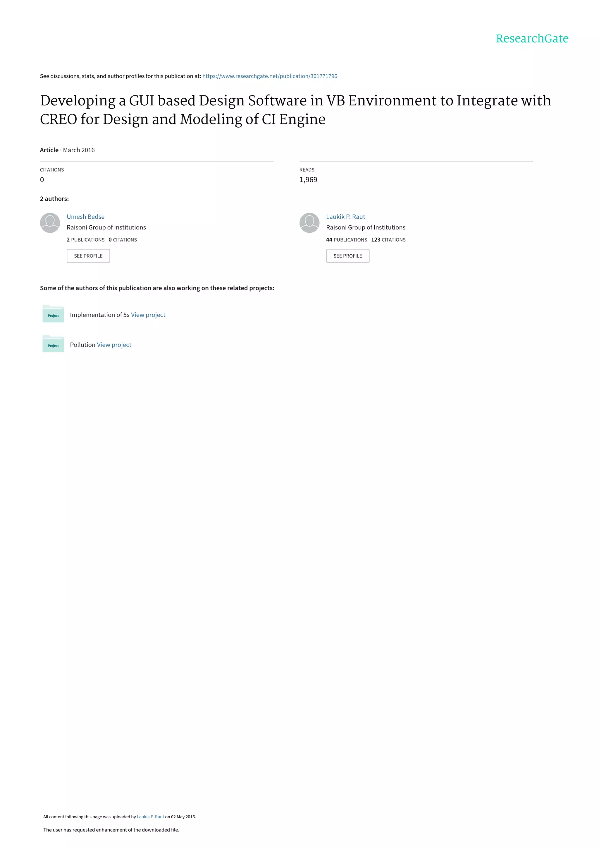
A. Development of GUI using Visual Basic
In this paper, developed GUI is made for the case study of design of CI engine parts like cylinder head, cylinder
block, piston and crankshaft. CI engine is having many numbers of mechanical components, but parts named
above are the most important parts of any CI engine. So design of these parts is useful to take into account to
develop a GUI.
Input Variables for design of cylinder block
Brake Power (watt)
Speed (RPM)
Mean Effective Pressure (MPa)
Number of Strokes
Allowable circumferential stress (MPa)
Output Variables
Bore (mm)
Length/Stroke (mm)
Input Variables for design of piston head
Explosion Pressure (MPa)
Bore (mm)
Bending Stress (MPa)
Cylinder Wall Pressure (MPa)
No. of Piston Rings
Output Variables
Thickness of Piston Head (mm)
Thickness of Ribs (mm)
Radial Thickness of Piston Ring (mm)
Clearance
Axial Thickness of Piston Rings (mm)
Input variablesfor design of crank shaft
Bore (mm)
Length (mm)
Explosion pressure (MPa)
Output variables
Dia. Of crank pin (mm)
Length of crank pin (mm)
Bending moment at the crank pin (N-mm)
Bending stress (MPa)
In above input variables, some variables like allowable circumferential stress for cylinder, bending stress
and cylinder wall pressure for piston design depend on the selected material. With this developed GUI, it has been
observed that the design of these parts is done within few seconds while these calculations takes much time when
done manually.
International Journal of Latest Trends in Engineering and Technology (IJLTET)
Vol. 6 Issue 4 March 2016 375 ISSN: 2278-621X
5. Figure 1: Developed GUI using Visual Basic
a) Coding for Design of Cylinder Block
PrivateSubcmd_designcb_Click(ByVal sender
AsSystem.Object, ByVal e AsSystem.EventArgs)
Handlescmd_designcb.Click
Dim bp, N, s, d, l, ip, t, sigmat As Integer
Dim pm, p, c, mecheffAsDouble
bp = Integer.Parse(txt_bp.Text)
N = Integer.Parse(txt_speed.Text)
pm = Double.Parse(txt_pm.Text)
mecheff = Double.Parse(txt_mecheff.Text)
s = Integer.Parse(txt_strokes.Text)
c = Double.Parse(txt_clearance.Text)
sigmat = Integer.Parse(txt_tensile.Text)
ip = bp / mecheff
d = Math.Pow(((60 * 1000 * 4 * ip) / (pm * 1.5 *
3.1415 * (N / 2))), (1 / 3))
l = 1.5 * d
p = 9 * pm
t = d * Math.Sqrt((c * p) / sigmat)
txt_bore.Text = d.ToString()
txt_thickness.Text = t.ToString()
txt_length.Text = l.ToString()
txt_borepiston.Text = d.ToString()
txt_bor.Text = d.ToString()
txt_len.Text = l.ToString()
txt_boresimulate.Text = d.ToString()
txt_stroke.Text = l.ToString()
txt_boresimulate.Text = d.ToString()
txt_stroke.Text = l.ToString()
txt_speedsimulate.Text = N.ToString()
EndSub
Where, bp= Brake power (W)
N= Speed (rpm)
s= stroke (mm)
d= bore of piston (mm)
l = length of stroke (mm)
ip= indicated power (W)
pm= mean effective pressure (MPa)
p= maximum pressure in the engine cylinder
t= thickness of cylinder (mm)
c= clearance (mm)
mecheff = mechanical efficiency
b) Coding for Design of Piston
PrivateSubcmd_designpiston_Click(ByVal sender
AsSystem.Object, ByVal e AsSystem.EventArgs)
Handlescmd_designpiston.Click
Dim pe, dp, sigmat, th, tr, t1, pw, ta, nr As Double
pe = Double.Parse(txt_explosionpressurepiston.Text)
sigmat = Double.Parse(txt_bendstresspiston.Text)
pw = Double.Parse(txt_cylinderwallpress.Text)
nr = Double.Parse(txt_noofrings.Text)
dp = Double.Parse(txt_borepiston.Text)
th = Math.Sqrt((3 * pe * dp * dp) / (16 * sigmat))
tr = th / 2
t1 = dp * Math.Sqrt((3 * pw) / sigmat)
ta = dp / (10 * nr)
txt_thickofpistonhead.Text = th.ToString()
txt_thickofribs.Text = tr.ToString()
txt_radialthick.Text = t1.ToString()
txt_axialthick.Text = ta.ToString()
txt_pressure.Text = pe.ToString()
EndSub
cmd_desi
gncb
cmd_designpis
-ton
cmd_cs
International Journal of Latest Trends in Engineering and Technology (IJLTET)
Vol. 6 Issue 4 March 2016 376 ISSN: 2278-621X
6. Where,
pe= maximum gas pressure or explosion pressure (MPa)
dp= bore of piston (mm)
sigmat = permissible bending (tensile) stress for material of
the piston (MPa)
th = thickness of piston the head (mm)
tr = thickness of ribs
t1= radial thickness
pw= cylinder wall pressure (MPa)
nr = no of rings
na= axial thickness
c) Coding for Design of Crank Shaft
PrivateSubcmd_cs_Click(ByVal sender AsSystem.Object,
ByVal e AsSystem.EventArgs) Handlescmd_cs.Click
Dim d1, len, p, fp, dc, pb, lc, m, z, sigmab, bendstress, d2, t,
l1, m1 AsDouble
d1 = Double.Parse(txt_bor.Text)
len = Double.Parse(txt_len.Text)
p = Double.Parse(txt_pressure.Text)
pb = 10
sigmab = 60
fp = (3.1415 / 4) * d1 * d1 * p
dc = Math.Sqrt(fp / (0.8 * pb))
lc = 0.8 * dc
m = (3 / 4) * fp * lc
z = (3.1415 / 32) * dc * dc * dc
bendstress = (m / z)
t = 0.6 * dc
l1 = 1.7 * dc
m1 = fp * ((0.75 * lc) + (t) + (5 * l1))
d2 = Math.Pow((m1 * 32) / (3.1415 * sigmab), (1 / 3))
txt_pistongasload.Text = fp.ToString
txt_bmcrankpin.Text = m.ToString
txt_bendingstress.Text = bendstress.ToString
txt_diacrankpin.Text = dc.ToString
txt_lencrankpin.Text = lc.ToString
txt_bearing.Text = d2.ToString
EndSub
Where,
d1= piston diameter or cylinder bore (mm)
len= length of stroke (mm)
p= maximum intensity of pressure on the piston
(MPa)
fp= gas load on the piston
dc= diameter of crank pin (mm)
pb= permissible bearing pressure (MPa)
lc= length of the crank pin
m= maximum bending moment on the crank
web (N- mm)
z= section modulus (mm^3)
sigmab= allowable bending stress (MPa)
bendstress= bending stress (MPa)
d2= diameter of shaft
B. Transfer of ouput data from GUI to Excel sheet
CAD software like Creo Parametric, CATIA, Pro/E are having the facility to import data from different database in the form of
excel sheet to update the model. This type of integration of different software is very useful to do automation in mechanical design
which saves a huge amount of design time. In this paper, output from the developed GUI is exported to the excel sheet as shown by
clicking on the button Excel File in the GUI and this output will be helpful to integrate with the Creo Parametric 2.0 to do design
automation. After integration, user can simply modify the CAD model just by modifying excel data sheet.
Figure 2: Output in MS-Excel sheet
International Journal of Latest Trends in Engineering and Technology (IJLTET)
Vol. 6 Issue 4 March 2016 377 ISSN: 2278-621X
7. C. Integration of Visual Basic and CREO using Excel Sheet
Figure 3: CAD model of Assembly of CI Engine
CAD model of assembly of CI Engine shown in figure 3 having basic important parts as piston, cylinder block with fins attached,
connecting rod, crank shaft , crank pin etc.
D. Procedure of integration :-
To understand the concept of integration, here example of piston has taken. After creating excel sheet, open individual
parts of assembly. With the help of analysis menu available in Creo Parametric 2.0 in that go to excel analysis. New
window will appear on screen as shown in picture. Go to load file as marked 1 in circle and load that excel file generated
using visual basic then select output values of design of that particular part then click on output cells button marked as 2
then click on compute button marked as 3. Then go to add feature and enter the name of that excel file there and close this
window. Then go to tools of menu bar, in that click on relations. Here assign all required dimensions to be updated from
excel sheet to the dimensions of model. So the software will understand that which cell value of excel sheet is for which
dimension of model. User should know that which output value is going to be use for which dimension
Figure 4: Excel Analysis in CREO
1
3
2
International Journal of Latest Trends in Engineering and Technology (IJLTET)
Vol. 6 Issue 4 March 2016 378 ISSN: 2278-621X
8. After all these actions, just go to model menu on menu bar and click on regenerate marked as 4 in picture
shown. This completes the complete procedure of model updating of that particular part. Further user wants to
update the dimensions of that model then just go to excel sheet as marked as 5 and right click on that and click
on edit definition then click on next button. As user clicks on next button excel file gets open on screen, just
update that sheet and regenerate the model. Within seconds, models gets updated. Repeat the same procedure for
all parts. After update of all individual parts of any assembly just open assembly file and click on regenerate
button , automatically complete assembly gets updated. Firstly user has to do these first 4 steps, after these 4
steps user has to only open excel sheet and update that excel sheet to get required updated model.
Figure 5: Regeneration of new updated model
E. Simulation of CI engine processes
In engineering, simulation process has come to mean developing and using the appropriate combination of
assumptions and equations that permit the process to be analyzed. The modelling of engine processes continues
to develop as our basic understanding of the chemistry and physics of the phenomena of interest steadily expands.
Computer simulation activities can make major contributions to engine design at different levels of generality or
detail, corresponding to at different stages of model development.
In the above shown GUI, one column of simulation having input variables bore, stroke, connecting rod length,
speed and compression ratio is there. With the help of these inputs, simulation of CI engine process will be done
in the form of real time graphs of Pressure (bar) Vs. Crank angle (degree), Volume (cc) Vs. Crank angle (degree)
and Temperature (Kelvin) Vs. Crank angle (degree). Here simulation is done for compression stroke, combustion
stroke and expansion stroke of CI engine and gives each value of pressure, temperature and volume at each crank
angle in the form of real time graph as shown. With this, user can easily analyze how the process is happening in
the engine.
4
5
International Journal of Latest Trends in Engineering and Technology (IJLTET)
Vol. 6 Issue 4 March 2016 379 ISSN: 2278-621X
9. IV.CONCLUSION
Nowadays it is very important to make maximum automation in all the sectors or department of an industry.
With the help of this integration of developed GUI and parametric modeling software or CAD packages available
in the market has lots of potential to reduce design time by huge amounts. It has been observed that among all
computer programming languages available Visual Basic is more suitable and similarly in the case of CAD
software CreoParametric 2.0 is more suitable for design automation. The software developer has the freedom to
develop more and more advance software. In future, integration of design and modelling phase can be extended
to integrate with an analysis phase to do the complete automation which will play very crucial role in automation.
V. REFERENCES
[1] K. M. B. Indrajitsinh J. Jadeja, "Developing a GUI based Design Software in VB Environment to Integrate
with CREO for Design and Modeling using Case Study of Coupling," International Journal of Engineering
Sciences & Research Technology, pp. 4089-4095, April, 2014.
[2] A. R. Abhishek C. Lad, "Design and Drawing Automation Using Solid Works Application Programming
Interface," International Journal of Emerging Engineering Research and Technology, vol. Volume 2, no.
Issue 7, pp. 157-167, October 2014.
[3] M.-C. S. V. C. L. Chih-Hsing Chu, "Computer aided parametric design for 3D tire mold production,"
Computers in Industry An International, Application Oriented Research Journal, vol. Volume 57, no. Issue
1, p. 11–25, January 2006.
[4] D. Shah, "Parametric Modeling and Drawing Automation for Flange Coupling," International Journal of
Research in Engineering & Technology (IJRET), vol. Vol. 1, no. Issue 2, pp. 187-192, July 2013.
[5] U. M. N. Yogesh H. Sawant, "Automated Modeling of Screw Conveyor Components in CATIA,"
International Journal of Engineering and Technical Research (IJETR), Vols. Volume-3, no. Issue-4, pp.
112-116, April 2015.
[6] Q. W. L. C. Zhongtu L., "A Knowledge-based Approach for Task Implementation in Mechanical Product
Design," International Journal of Advance Manufacturing, pp. 837-845, 2006.
[7] G. D. I. G. G. Saša Ćuković, "Automatic determination of grinding tool profile for helical surfaces
machining using catia/vb interface," U.P.B. Sci. Bull., Series D, vol. Vol. 72, no. Iss. 2, pp. 85-96, 2010.
[8] G. U. T. J. G. Daniel J Fonseca, "A Knowledge-based System for Conveyor Equipment Selection," Expert
Systems with Applications, vol. Volume 26, no. Issue 4, p. Pages 615–623, May 2004.
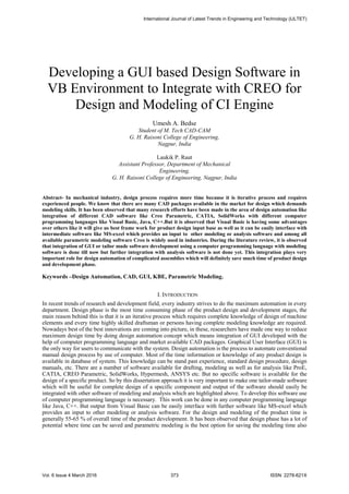
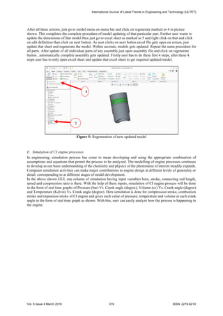
Figure 6: Graph of Pressure vs Crank Angle Figure 7: Graph of Volume vs Crank Angle
International Journal of Latest Trends in Engineering and Technology (IJLTET)
Vol. 6 Issue 4 March 2016 380 ISSN: 2278-621X
10. [9] H. Hussein, "Computer Aided Blanking Die Design Using CATIA," Procedia CIRP, vol. Volume 18, p.
96–101, 2014.
[10] Z. S. M. Y. A. S. Mei Zhongyi, "Research on Knowledge-based System for Typical Aircraft Composite
Component Design," Advanced in Control Engineering and Information Science, p. 1431 – 1435, 2011.
[11] V. Gulati, "Parametric Jewelry Modeling in AutoCAD using VBA," International Journal of Computer
Application, vol. VOLUME 1, no. ISSUE2, pp. 158-164, FEBRUARY 2012.
[12] A. H.K., "3-D Geometric Modeling for the 21st Century," Engineering Design Graphics Journal, vol. 63,
pp. 33-42, 1999.
[13] J. Monedero, "Parametric design: a review and some experiences," Automation in Construction, vol.
Volume 9, no. Issue 4, p. 369–377, July 2000.
[14] L. L. Guo Peipei, "Parametric design of gear shaft based on Pro/E," in 2011 International Conference on
Electronics, Communications and Control (ICECC), Nigbo, China, 2011.
[15] D. B. S. K. M. P. Ruchik D. Trivedi, "3D Parametric Modeling for Product Variants Using Case Study on
Inner Ring of Spherical Roller Bearing," in Chemical, Civil and Mechanical Engineering Tracks of the 3rd
Nirma University International Conference on Engineering, Ahmedabad, 2013.
[16] H. H. J. A. Q. U. U. R.K. Abdel-Magied, "Computer Aided Design of the Die-Set for Sheet Metal Punching
and Blanking Dies," Applied Mechanics and Materials, vol. Volume 619, pp. 78-82, 2014.
[17] S. J.Shankar, "Automation of Design by Integrating Pro/Engineer with Ms-Excel," IOSR Journal of
Mechanical and Civil Engineering (IOSR-JMCE), pp. 69-72, 2014.
International Journal of Latest Trends in Engineering and Technology (IJLTET)
Vol. 6 Issue 4 March 2016 381 ISSN: 2278-621X
View publication statsView publication stats