SlideShare a Scribd company logo
1 of 17
Download to read offline
International Journal of Computer-Aided Technologies (IJCAx) Vol.2, No.3, July 2015
DOI:10.5121/ijcax.2015.2302 11
Developing Product Configurator Tool Using
CADs’ API with the help of Parametric Modeling
for Design Automation of Hydraulic Actuator.
A.K. Patil1
and R.B. Buktar2
1
Post Graduate student, Department of Mechanical Engineering, SPCE, Mumbai-58
2
Professor and Head of the Department (Mechanical Engineering), SPCE, Mumbai-58
Abstract
Order placingis a crucial phase of lifecycle of a Mass-customizable product and seeks improvement in
Mechanical industry. ‘Product Configurator’ is a good solution to bring in data transparency and speed
up the process. Configuration tools arebeing used on a very small scale,reasons being lack of awareness
and dearer costs of existing tools. In this research work a product configurator is developedfor
Hydraulic Actuator (HA).This method uses Applicable Programing Interface (API) of a CAD tool coupled
with Visual Basics (VB) and MS Excel.Itis a standaloneapplication of VB and its integration into web
portal can be the future scope. The final aim was to reduce time delay at CRM phase,bring more
transparency in the ordering system and to establish a method which, small and medium scale enterprises
canafford. Trails on the tool developed generated Part-Assembly drawings, BOM and JT files in
moments.
Keywords:
Mass Customization, Configuration, CAD, API.
1. Introduction
Shopping, few years back was a customer-manufacturer face to face scenario, but now it’s a
web-portal and GUI, which takes care of all the business deals, placing order, payment till
delivery. The scenario is known as E-shopping, and it has become an integrated routine for all
of us. Though the concept is in Adam n Eva stage as far as mechanical industries are
concerned.Precisely, there is a gap between customer’s needs and producers capabilities. To
bring more modernization and flexibility to customers’ requirements, a tool called
‘Configurator’ was introduced where a customer can select as many specifications as per his
requirements from the available and suitable database, via UI of the websites’ portal and the
program would customize the product depending upon the selected parameters and display the
possible suggestions. Efforts are being made to set up the trend in the field of Mechanical
Engineering.
Figure 1. CRM & ERP two conjunctions of PLM
CRM
PLM
ERP
International Journal of Computer-Aided Technologies (IJCAx) Vol.2, No.3, July 2015
12
Mass customization has led to customer oriented approach and high productivity, hence
accelerating the growth of company. In response to this technology, automobile companies have
introduced product/sales configurators to automate the order handling process according to the
customer requirements.
 It is a production strategy focused on the broad provision of personalized products and
services, mostly through modularized product/service design, flexible processes, and
integration between supply chain members.
 For past one decade it has been observed that major developments such as the heavy use of
web-based configurators, the emergence of rapid manufacturing technologies, and the
implementation of more structured customer-interaction methods are the keys to the success
of the Mass Customization.13
Product configurator is a tool used especially for the sale of configurable products and in
some cases implemented within an Enterprise Resource Planning (ERP) system to speed-up the
lifecycle of a product. It can be seen as the initial phase of PLM. A product configurator
signifies the producer’s awareness of customer’s needs and the capability to fulfill these needs
with respect to its product offerings.
Advantages of using configurator technique are:
 Transparency in data sharing and product sales,
 Easy and effective way for sales people to negotiate over prices,
 Reduce customer’s confusion,
 Speed up ERP system and hence reducing delay time in order to speed up production phase,
 Impossible combinations or promises can be avoided.
Somehow, customer’s perspective is neglected or on other side they are not technically sound at
their best. Also, the importance is given to the performance based parameters and aesthetics of a
product, nowadays.This is injustice to the technically sound customers and inadequacy in
creating awareness in the confused customer. A Configurator can be effectively put into the
routine as the remedy.
Hydraulic Actuatorsare under consideration here as they are used in industrial process control,
employ hydraulic pressure to drive an output member. However, it should be noted that the aim
behind this is, merely, to establish the concept of configurator in terms of any one mechanical
product; differently any other product would have been considered for the same.
 Hydraulic Actuators are used where high speed and large forces are required. The fluid used
in hydraulic actuator is highly incompressible so that pressure applied can be transmitted
instantaneously to the member attached to it.
 Practical application of actuator is however different than the theoretical one. Here few more
accessories and supporting instruments are supposed to be attached for the proper
functioning of the actuator for the specified purposes.
 The product finds its significance in many heavy duty operations as well as in automation
field. So this product was selected as the center of this research work.
It’s important to understand that though a specific product is selected for this project, the
main idea is to establish a method/ develop a tool only. So randomly any product could be
selected whose mass customization is possible. There are no special criteria involved in
selecting this product here. In short HA is merely a product here to demonstrate the working of
International Journal of Computer-Aided Technologies (IJCAx) Vol.2, No.3, July 2015
13
Figure 2. Schematic of Hydraulic Actuator with important parts
the new tool i.e. Configurator. Since the project is going to concentrate on HA more, a detailed
technical discussion is mentioned ahead about this product’s parameters, interrelations and
method of coding them into the main program.
1.1 Concept Initialization and Steps involved:
It was decided to coupleCADs’ API and parametric modeling, in Solidworksto develop such a
configurator for the producer’s portal. The method uses Visual Basics to generate UI, and which
can bring about changes in the CAD model of the component depending upon given inputs by
user. Final results expected are part/ assembly drawings, BOM, JT files etc.Solidworks, Visual
Basics and MS-Excel arethe toolsutilized in this investigation. All these aspects are discussed
further in details, but few steps must be mentioned here:
 A database was generated, with the help of HA producing firm.
 Basic Modeling was carried out in SOLIDWORKS 2014 interface.
 A design process was referred to establish relationship between different parameters of HA,
which thereafter was implemented in coding phase.
 An API procedure was followed to couple CAD, VB and MS Excel with parametric
modeling, to develop the code.
 A beta version was release so as to use it as a standalone application.
 Final output: A model of Hydraulic Actuator can be displayed, depending upon
customization from the customer and subsequently generation of drawings and BOM, which
can be processed directly into ERP system for the production department.
At present the scope of this study is to develop a standalone application in VB which can be
accessed from any PC having Solidworks installed.
2. Related Work
2.1 Literature Survey
This projectmainly aims at automation for the mass customization technique in industry. So this
study is about techniques which deal with interrelations between various elements or precisely
International Journal of Computer-Aided Technologies (IJCAx) Vol.2, No.3, July 2015
14
objects. These objectives can only be achieved with the help of computer based subjects and
methods which involve coding and aligned concepts. So it was decided to make a survey of
related research work. Initially some steps were proposed like development of a master model,
relationships between various dimensions and subassemblies which can modify themselves with
the driver dimensions as inputs, inclusion of some design factors like shell design etc. and a
User Interface (UI) to control all these activities in the back end. Through this literature survey
the author has tried to verify his methodology, adapt new techniques and to modify the existing
ones.
The general approach which was found in all the papers referred was to put forward the
controlling equations, managing the database, solving problems involving configuration, to
avoid conflicts, which generally are caused due to mass customization and represent the
configurator.
P.T. Helo, Q. L. Xu and team members have proposed a vehicle configuration system using
Citarasa Ontology, which is a coherent business model which combines the domains of mass
customization.1
AlessioTrentin, Elisa Perin and CiprianoForza in their paper discuss testing the
positive impact of product configurator use on time performance on manufacturing plants.2
Anders Haug and Lars Hvamb define and compare seven different strategies for the
development of product configurators against the generalized one.3
Martin Landherr and
EngelbertWestkämper describe the method for integrated product and assembly configuration.4
Dong Yang and Ming Dong present a method of applying constraint satisfaction to resolve
product configuration conflicts. 5
BulutAslan, Mark Stevenson and Linda C. Hendry have
discussed regarding assessing the fit or alignment between ERP functionality and a Make-To-
Order production strategy, which is highly required for the functioning of a configurator.6
JuhaTiihonen, TimoSoininenand team describe a novel configurator prototype that supports
configuring, a mass customizable product; which contains a semi-visual modeling tool based on
a high-level object- and product structure-oriented modeling language.7
Whereas Dong Yang
and Ming Dong present a novel and direct approach to encoding configuration models into the
Dynamic Constraint Satisfaction Problems.8
D. Mourtzisa and M. Doukasa describe a novel
software architecture that facilitates the ability to visualize and manipulate three-dimensional
product design parameters under constraints where the manipulation is performed in real-time,
over web, comprising Virtual and Augmented Reality functionalities.9
Jonas Landahl proposes a
distinction between limiting and managing product complexity, and stress that these approaches
affect internal cost over time differently, using a coding method, but is costly.10
Kenn Steger-
Jensena and CarstenSvensson have discussed issues with existing systems for Mass
customization and IT solutions possible for the same.11
GüntherSchuha, Stefan Rudolf and
Michael Riesenerapropose a methodology which allows companies to determine the "optimal
configuration" of a product based on similarities between a new product variant and existing
variants. This is exclusively related to the costs framed at the ordering phase, in optimal way.14
C. Forzaa and F. Salvador report a case study of the implementation of a product configuration
software in a small manufacturing enterprise; specifically, about the significant benefits that the
company enjoyed from the implementation of the software, especially in terms of delivery time
and customer relationships.15
Few others have contributed to this field. Literature survey highlights following points:
 It is clear that the technology is notnew to the field of Automation whereas on other side it’s
not even fully defined, means it has a lot of scope for the improvements and research.
 It is also observed that such technologies are being used on a large scale by large scale
Industries but the same technology has failed to impress the small and medium scale businesses.
International Journal of Computer-Aided Technologies (IJCAx) Vol.2, No.3, July 2015
15
 The reasons behind this could be lack of awareness, absence of properly established CRM
phase or even inertia towards the conventional methods for the product sales and marketing
strategies and order placement and execution.
 But the main reason can be related here is cost of the technology. These techniques, no
doubt, are based on CAD; so workstation is highly required, no matter a small one or a complete
system comprising of multiple machines, it has to be there but the cost of coding and installing
these technologies for such small and medium scale firms can surplus the budget. Also there is
a major issue with the payback period for the same.
 The basic requirements like server, network cables and channels and provision for the
DBMS are not cost effective as far as the existing configuration systems or software/ tools are
concerned. It should be understood that a skilled programmer is required to develop such tools.
2.2 Industry Survey
When it comes to ordering a hydraulic actuator from its manufacturers, there are so many
parameters which are supposed to be provided. This is sometimes troublesome for a buyer to
provide all such details, due to lack of technical details of the product.Nevertheless, many
customers have cognizance of the significance or the selection criteria for the components. But
the imbalance between technical knowledge of customers aboutthese parameters and available
selection provisions in terms of technical things mainly happens due to telephonic enquiry or
mail based enquiry. With the same intensions, when an online industrial survey was carried out,
several drawbacks of the ordering systems came into picture.
2.2.1 Problems with Contemporary Systems (HA order placing)
 Some HA providers have provision for entering only dimensional and other non-technical
details of the product.
 Such industriesaccept no technical specifications or details which can play any role in mass
customizing such products. The survey carried out explains, the failure in CRM scenario,
here, in case of Hydraulic Actuator industry.
 No technical details are being exchanged by industries as far as ordering the product is
concerned. Even existing configurators do no perform to the expectations. Details of these
surveys can be studied through successive discussions.
 Manufacturers (under survey) asked for the stroke length and bore diameter, remaining
things like material, series of HA, rod size, load to be lifted etc. were simply neglected in the
discussions carried out for the market survey.
 In other words it was found thatManufacturers assume, conveniently, that the customer is
well aware about technical and analytical aspects of HA, which not necessarily holds true
always.
 There is least involvement of a customer when it comes to make choices in regards with
exact requirements. Differently, Manufacturer fails to provide guidelines to a customer when
it comes to select various parameters or enter required inputs. This causes perplexed like
situations while placing an order, here in case of HA.
The general ordering scenario follows following sequence:
 The enquiry by customer telephonic/ mail based/ online applications.
 Cross enquiry by the manufacturer’s CRM department and asking for technical parameters
like bore diameter and stroke length.
 Matching of this order with the standard design available with the manufacturer and sending
the quotations for the same, based on available combinations only, to the customer.
International Journal of Computer-Aided Technologies (IJCAx) Vol.2, No.3, July 2015
16
Software 1
Software 2
New Software Tool
Details asked about HA parameters
Quotations of available match
Enquiry from Customer End
Reply with details available
CRM: Manufacturer Customer
Figure 3. Existing System of order placing
 Upon agreement, placing of order by the customer.
 Instructions from CRM to form BOM and further process in ERP.
 The method generally takes 3-4 days, where the purchasing something feels like a boring
process also customer many a times have no single idea about how his end product is going
to look like. The tool of configurator tries to minimize this time lag. The same is explained in
the following graphics. These consequences have been observed by the authors themselves
in reality.
This research paper has discussed a method by means of which a cost effective technique or tool
(Configurator) can be developed. The main objective thus was to develop a standalone
application (with User Interface) that will serve the purpose of easing the process of placing
order for a product i.e. HA, which will be able to generate the BOM and Product Drawings
ready to incorporate in ERP system and production department. The author will try to reach out
and propose an HTML version in extension to this work which is a replica of the web based
system.
3. Product Configurator Tool:
3.1. CAD’s API:
As discussed earlier the existing configurators use hardcore coding as the backend tool. The
feasibility and cost effectiveness of such techniques are few of the major issues. So a midway
technique which is easier to understand and cheaper to develop is discussed below:
3.1.1. Applicable Programing Interface (API)
Figure 4. Concept of API technique'
The idea behind this project was to use two or three software tools that are used by any firm in
general, club them so as to obtain a modified version of the software which will take out
International Journal of Computer-Aided Technologies (IJCAx) Vol.2, No.3, July 2015
17
benefits from all these clubbed software and will give desired output. The method is called as
API. Coding under API varies software-software, but the basic technique is same to connect two
or more tools with a UI to get the desired work done. In this investigation, Solidworks API
technique is used.
This comes for C, C++ and VB, out of which API help menu for VB of Solidworks was
extensively used. Basically the technique treats various functions under Solidworks as classes
and all instances where these functions are invoked are considered as objects of these classes.
The method finds a hierarchical structure arranged with these classes and objects. However the
scope of this report is limited to the use of the technique, hence no in depth discussion of the
coding language is mentioned. In this study, CAD software i.e. Solidworks, DBMS tool i.e. MS
Excel and GUI package i.e. VB are utilized to develop ‘Configurator’.
Mainly such kind of application is useful by sales personnel to get on spot orders or to
demonstrate the use of this tool. In later part it is discussed about how to convert this standalone
system into an HTML code so that the same can be accessed form web by any customer.
3.1.2. Selection of tools, techniques and Pre-requisite
 The database generation was a big issue, though the study is to establish a method only. So
another survey was conducted in which a detailed data (part lists and a wide database)
regarding HA was made available by a company producing HA. In other case if the data was
not available, one would have to generate the data using standard design procedures for
complete HA.MS Excel was used for this purpose as it finds easy integration with both
Solidworks as well as VB.
 Secondly a strong but user friendly modeling tool, Solidworks, is the heart of this project,
where API coding can be done with less complexity when compared with other packages.
One more advantage is that the Solidworks can be incorporated with the MS Excel and VB
easily via macro creation. Writing, recording and editing API code as per requirement is very
much simple in Solidworks environment. One can use other tools also, but their integrality
with other two software is a matter of research, on the other hand Solidworks comes with
many user friendly operations and easy to understand.
 A workstation with a 4GB RAM, installed with at least win7, Solidworks and MS Excel are
the basic requirements of this project work. In addition DB is available. The next steps are to
find out parametric relationships and develop appropriate method to develop configurator.
Solidworks
for
modeling
MS Excel for
Data-Base
Visual Basics
for (UI)
OUTPUT
Figure 5. Flow of data through tools selected
International Journal of Computer-Aided Technologies (IJCAx) Vol.2, No.3, July 2015
18
3.1.3. Modeling
As discussed earlier a master model is required to provide base for rebuilding various
configurations. From the data available a random configuration was selected and separate parts
and ultimately assembly of HA were modeled in Solidworks environment. Each dimension was
named separately so as to use the tags in parametric modeling. Using these model further
iterationswas carried out, as mentioned ahead. Few models,assembly are as below.There
aretotally 56 no. of major dimensions involved as far as a configuration is concerned.
Remaining parametric relations took effect after design and rework stage, the same is discussed
in subsequent section. Solidworks 2014 was used for the modeling purpose. Individual parts
were modeled first with all required tags and then assembly was done. The extension possessed
by parts is .sldprt and that by assembly file is .sldasm. It must be mentioned that in order to
work this assembly properly, all the parts and assembly files should be maintained in a same
folder/ location. The same is valid for any no. of assembly is as below.Minor changes were
considered for the missing dimension links, but as far as the scope of the research is concerned,
it remains valid.
3.1.4. Database Management (DBM)
There are some 9 different series available on AH’s website. Two of them were selected for this
study. Even with these two, for these six basic parts, there is huge dataavailable, which needed
to be arranged properly, and this was done using MS Excel. This approach is useful to
determine no. of configurations and
organize part dimensions properly. A Sample table is shown below for just one part.
Bore
Diameter
Base Plate Dimensions
(inch)
A B C
2 2.38 0.5 0.25
3 3.38 0.59 0.25
4 4.5 0.75 0.38
5 5.56 0.88 0.38
6 6.75 1 0.38
7 8 1 0.38
8 9 1 0.38
Table 1. A sample database Figure 7. Base Plate (Basic Dimensions)
Figure 6. Exploded view of HA assembly with part names
International Journal of Computer-Aided Technologies (IJCAx) Vol.2, No.3, July 2015
19
It must be mentioned that apart from these three basic dimensions used, few other will be in
picture when parametric modeling will be introduced.
3.2. Design, Calculations and Parametric Modeling
The concept of mass customization using configurator tools available, works on the basis of
dynamic selection and modeling. This involves conflict solving tools and coding to prevent
impossible combinations. This study work has tried to by-pass this approach and keeps these
things in semi dynamic state. For this few calculations were studies from HA design and
parametric modeling was applied, the same is discussed in brief:
3.2.1.Design:
 Range of working pressure: 2500psi, 3000psi
 Material of cylinder: Stainless Steel ( = 20000 psi)
 Load to be lifted (varying)
 Stroke Length/ Elevation in terms of lift
Depending upon the inputs, a range of cylinder thickness and Bore diameter is calculated. Using
DB form AH and few calculations following thickness was calculated and rounded up to
standard thickness.
 Desired Bore Diameter =
4
Pr
Load
essure



 Select nearest Standard Bore Diameter (BD)
 Cylinder wall thickness = 
 
2
1 ((0.5 ( Pr ) (0.25 ))
2 ) 2
2 ( (( Pr ) / 2))
essure Diameter
essure

 
   
  
 
12
 Select suitable rod diameter from available DB
Bore Diameter
(inch)
2 3 4 5 6 7 8
Wall thickness
(inch)
2500 psi 0.134 0.2008 0.2678 0.3347 - - -
3000 psi - 0.2447 0.3263 0.4079 0.4895 0.5710 0.6526
All these design criteria were incorporated during formation of parametric relations.
3.2.2.Parametric Relations:
The configurator will be used under circumstances where mass customization comes into
picture; so ultimately, parametric relationships will take part into process so that dynamic
changes to the model can be imparted. There are many parameters involved when it comes to an
assembly and as far as mass customization is concerned there has to be a large amount of data to
be considered for the multiple configurations. And this is the reason the project is titled using
these keywords, ‘CAD’s API, parametric modeling and design’.
This was the crucial task. As it was discussed earlier that the existing configurators use DBMS
for the dynamic assignment, it takes lot of efforts and systematic coding. The author is
proposing a parallel method in this study where Parametric Relations (PR)will control the
Table 2. Minimum shell thickness based on Bore diameter and pressure series available
International Journal of Computer-Aided Technologies (IJCAx) Vol.2, No.3, July 2015
20
Figure 8. Parametric drafting for piston menu (Solidworks)
modeling phase, i.e. Parametric Modeling (PM). Apart from the design inputs mentioned above
there are two major constraints which can affect the configuration process.
 Desired Stroke length by the customer
 Infinite number of combinations of various components depending upon the nature of duty
imposed
To overcome this problem it was decided to establish relations between various parameters like
inputs from user and various dimensions of the parts. All such relations can be used in the
geometry itself so that there will be two or three driving inputs and rest all are driven
parameters. If one looks at the DB, it seems quite difficult task, but the method of API
associated with Solidworks has made it simple, the same is discussed in detail in later part. This
can be implemented during both modeling and API phases. A sample PM is elaborated through
an example below:
It can be seen that there is hierarchy involved as far as dependency of various dimensions is
concerned. So logically, if such dependencies can be mapped for the complete assembly it will
be helpful for the semi-dynamic changes to occur in the desired configuration. In this light
dimensions were categorized in following types and hierarchy order was decided.
The major problem involved was that the DB was only thing available, the relationships or the
judgments for the combinations of the parts were not mentioned or available, few of them were
derived from designed criteria, few were calculated. In this study there are more than 50 such
parametric relations derived or available. It must be mentioned that a few instances minor
assumptions were made, which no doubt, are in-line with the database available. After putting
them in the hierarchy format the next step is to implement Configuration Techniques.
International Journal of Computer-Aided Technologies (IJCAx) Vol.2, No.3, July 2015
21
3.3. Configuration Techniques:
Since it’s a kind of substitution for the existing program based method being derived, there were
few trial and errors involved. The same efforts are discussed in the form of techniques here;
there can be multiple methods, but these two, being aware of their advantages over other, were
specifically targeted and used to develop the desired technique.It is to recall that the major tools
used are Solidworks, MS Excel and VB.
3.3.1.Technique 1: Design Tables
There is a method available in Solidworks where one can create multiple models using a same
master model. The technique takes shape from Design tables. Design table is a systematic
arrangement of DB, in other words it is a matrix which controls the modeling of a part or the
assembly, dynamically. The table is formed using MS Excel. The same can be auto generated or
can be imported from the external file. There are syntaxes to be followed and then parameters
can be inserted in this file. One more advantage is that one can add these PR directly in the
cells. The technique is to implement at the components’ level and then at the assembly level.
This will add a number of configurations in the component file itself, there will be a tag
generated for each configuration in the design table. Now these tags need to be arranged in the
design table associated with the assembly. Once they are arranged, a number of configurations
get added to the assembly tree. These are the predefined models which get activated using same
master model upon invoking. Design table and configuration tree is shown in the images.
Direct Input
Dimensions
Change with Driver
Dimensions directly
Change with Driven
Dimensions
Designed Parameters
Depend upon Direct
Inputs
Dimensions with
Constant Value
Figure 9. Arrangement of dimensions as controlling parameters in hierarchy
International Journal of Computer-Aided Technologies (IJCAx) Vol.2, No.3, July 2015
22
One can add as many numbers of configurations as required. In this method all the parametric
equations can be added in the design table only or they can be used in an external Excel file and
DB can be created there. But this again leads to a huge data generation and management. This is
the simplest method where mass customization of model can be done. This is half way done.
But the important half portion required i.e. invoking a particular configuration from the design
table has no known way except selecting them manually. Initially, author had a plan of writing
an API code for this method but later on it was understood that the code as well as the method,
hereafter becomes complicated and may bring in more complexities in terms of coding. So this
method was stopped being studied for the desired tool.
3.3.2.Technique 2: Integration of Solidworks and VB &MS Excel using API
Almost all software with macro generation ability has some provision for API coding. Here in
this study Solidworks was selected because it is a very strong tool for API writing and
automating things the way user desires. Help menu of Solidworks provides detailed information
regarding API code writing using VB. This study has used Solidworks for parametric modeling
as well as API writing to integrate it with VB and DBM can be done using MS Excel. Consider
following block diagram:
Design Table for:
Piston
B@Sketch1
A@Sketch1
BD@Sketch1
$COLOR
$DESCRIPTION
$PARTNUMBER
Default 1.5 0.375 0.9985 15651299 Default $D
pistnB2R1S2 1.5 0.3755 0.9985 15651299 Default $C
pistnB2R1S4 1.5 0.3755 0.9985 15651299 Default $C
pistnB3R1.25S6 1.75 0.5005 1.4985 15651299 Default $C
pistnB3R1.5S6 1.75 0.5005 1.4985 15651299 Default $C
pistnB3R2S12 1.00 0.5005 1.4985 15651299 Default $C
pistnB4R1.5S10 1.75 0.6255 1.9985 15651299 Default $C
pistnB4R2S12 1.75 0.6255 1.9985 15651299 Default $C
pistnB4R2.5S12 1.75 0.6255 1.9985 15651299 Default $C
pistnB5R2S12 1.25 0.6255 2.4985 15651299 Default $C
pistnB5R2S14 1.25 0.6255 2.4985 15651299 Default $C
pistnB5R2S16 1.25 0.6255 2.4985 15651299 Default $C
pistnB5R2S18 1.25 0.6255 2.4985 15651299 Default $C
pistnB5R2S20 1.25 0.6255 2.4985 15651299 Default $C
pistnB5R2S22 1.25 0.6255 2.4985 15651299 Default $C
International Journal of Computer-Aided Technologies (IJCAx) Vol.2, No.3, July 2015
23
Solidworks Interface
[Master Model integrated
with Parametric Modeling]
User Interface (UI)
Asks for inputs like
Load, Pressure Series, Stroke
length
Output
Image
JT file
Part Drawings
Assembly Drawings
BOM
API
Code
Figure 10.Framework of Configurator components and their functions
So there are three main phases in which this method works. Third phase gives the desired output
and can be extended to a number of other applications as per requirements. API code connects
first and third phases to second one. There is two way communication between first and second
whereas second to third is just one way.
a. Unlike the Method 1, this method takes help of parametric modeling. All the relations
between various dimensions and variable or other inputs are embedded in the model itself. This
was one of the most crucial jobs to embed these relationships into model. Almost 50-60
relations and conditional statements are added in the master model. For this the tags given to the
parameters were used. This could be possible only because of Solidworks environment where
conditional statements and PR can be incorporated easily and with much more freedom.
b. Once it is done a model with capability to change its dimensions, for all parts and alternately
for the assembly, keeping physical relations between these parts intact. Now there are few
parameters, 5 in this case study, viz. Bore Diameter, Stroke Length, Rod Diameter, Material and
Load to be lifted are kept variables. In other words these are driver parameters.
c. Next important work is to form a UI; this can be done easily using VB. Now the UI and
Master Model have to be connected using an API code. This code can be generated using macro
recording facility as well as one can write it also. In this study the author has developed such a
code using macro recording and adding new code method to develop final API code. The code
takes help of IDoc2 method available with Solidworks API. A basic version of VB is sufficient
to incorporate this code in the UI.
d. After few iterations of debugging the code runs very well and desired changes do occur
perfectly in the model hence the method is confirmed.
International Journal of Computer-Aided Technologies (IJCAx) Vol.2, No.3, July 2015
24
3.3.2.1. PM of HA:
A sample PM is shown in the figure below. In the course to add these PR in the model, ‘IF’
statement is used extensively, as there are many conditional statements derived so as to match
the perfect combinations. Many other are simply equations that are also added in the same way.
It must be mentioned that the constrain satisfaction approach is very much important as adding
few equations or conditional statement where various parameters are involved differently, can
cause geometry errors which in turns stops the auto rebuilding of the model, causing error at the
backend, failing the configurator.One more important aspect is as per thehierarchy mentioned
earlier; some PR should be embedded in the component file only, whereas driver PR should be
implemented in the assembly file.
Figure 11.Solidworks interface to incorporate parametric relations into model
3.2.2.2 VB and UI- Integration through API
This is the nerve of the configurator tool. As mentioned above, the code can be written as per
the API syntax mentioned in Solidworks Help menu or from Solidworks website, also major
work can be saved by recording macro and generating code from that stage. Various codes were
generated for specific tasks like editing the driver dimension, saving the file and overlapping the
existing one, Saving JPEG, Drawing format of file, e-Drawing of the solid etc., these codes are edited
and rearranged in the VB coding window. These codes do have specific tags for the edited
parameters or save as path/ directory or method etc. VB standalone application will accept
values from user and will transfer it to these codes in the backend. Upon auto rebuilding the
assembly will incorporate the changes as per the parameters provided. Similarly, upon clicking
provided tab, the tool will save the documents in the desired format, especially, e-Drawings,
part and assembly drawings and BOM. A sample code is shown in the form of Image.
International Journal of Computer-Aided Technologies (IJCAx) Vol.2, No.3, July 2015
25
UI is not mentioned or described here as it is developer’s choice to decorate or arrange the VB
standalone application. In this case it was only for accepting few inputs and generates several
output files.
4. Results and Future Scope
The configurator was tested for two series of HA viz. 2500 psi and 3000 psi and the results
obtained were satisfactory. Hence this can prove a low cost and simple tool for small and
medium scale industries. Depending upon requirements this UI can be changed and betterment
can be brought about.
There is a limitation of current investigation that it is a standalone application and can operate
on a system where Solidworks is installed. But in the future scope this application can be used
as a web based configurator tool also. One way of doing this is convert the standalone form into
an HTML page and access the same, but this will again require Solidworks running on the
machine. Other way of doing this is to write the same code in .Net environment. It’s possible
then to access the same configurator from webpage. One more requirement for this kind of
method is installed application of Solidworks on some server which will be in the service
continuously. One benefit of this method is such a server can be provided like cloud based
system, where company does not require buying the server for its own and not even Solidworks.
The scope of this study was kept restricted to the standalone system only which can be used by
sales representatives to demonstrate or to accept orders from customer’s doors. The later method
would have resulted into out of scope research work, which requires Computer Engineering
skills. The suggested future work for the same work is first method where this standalone
application can be converted into HTML page. No doubt this application will make the make to
order process much comfortable.
5. References:
[1] P.T. Helo, Q.L. Xu, S.J. Kyllo¨nen, R.J. Jiao, Integrated Vehicle Configuration System-Connecting
the domains of mass customization, Elsevier, Computers in Industry 61 (2010) 44–52, July 2009.
[2] AlessioTrentin, Elisa Perin, CiprianoForza, Overcoming the customization-responsiveness squeeze
by using product configurators: Beyond anecdotal evidence, Computers in Industry 62 (2011) 260–
268, Elsevier, September 2010.
[3] Anders Haug, Lars Hvamb, NielsHenrik Mortensen, Definition and evaluation of product
configurator development strategies, Computers in Industry 63 (2012) 471–481, Elsevier, February
2012.
[4] Martin Landherr, EngelbertWestkämper, Integrated Product and Assembly Configuration Using
Systematic Modularization and Flexible Integration, Variety Management in Manufacturing.
Proceedings of the 47th CIRP Conference on Manufacturing Systems, Procedia CIRP 17 (2014) 260
– 265, Elsevier.
[5] Dong Yang, Ming Dong, A constraint satisfaction approach to resolving product configuration
conflicts, Advanced Engineering Informatics 26 (2012) 592–602, Elsevier, March 2012.
[6] BulutAslan, Mark Stevenson, Linda C. Hendry, Enterprise Resource Planning systems: An
assessment of applicability to Make-To-Order companies, Computers in Industry 63 (2012) 692–
705, Elsevier, May 2012.
[7] JuhaTiihonen, TimoSoininen, IlkkaNiemelä, ReijoSulonen, A Practical Tool For Mass-Customizing
Configurable Products, International Conference On Engineering Design, ICED 03 Stockholm,
August 19-21, 2003.
International Journal of Computer-Aided Technologies (IJCAx) Vol.2, No.3, July 2015
26
[8] Dong Yang, Ming Dong, Xiao-Kun Chang, A dynamic constraint satisfaction approach for
configuring structural products under mass customization, Engineering Applications of Artificial
Intelligence 25 (2012) 1723–1737, July 2012.
[9] D. Mourtzisa, M. Doukasa, A Web-based Platform for Customer Integration in the Decentralized
Manufacturing of Personalized Products, 45th CIRP Conference on Manufacturing Systems 2012,
Procedia CIRP 3 ( 2012 ) 209 – 214, Elsevier.
[10] Jonas Landahl, Dag Bergsjö, Hans Johannesson, Future Alternatives for Automotive Configuration
Management, Conference on Systems Engineering Research (CSER 2014), Procedia Computer
Science 28 (2014) 103 – 110, Elsevier, March 2014.
[11] Kenn Steger-Jensena, CarstenSvensson, Issues of mass customization and supporting IT-solutions,
Computers in Industry 54 (2004) 83–103, Elsevier, July 2003.
[12] Sumitshrivastva_blogspot_in_2012_09_design_calculation_analysis_Mechanical Guru’s blog
[13] Flavio S. Fogliatto, Giovani J.C. daSilveira, Denis Borenstein, The mass customization decade: An
updated review of the literature, Int. J. Production Economics 138 (2012) 14–25.
[14] GüntherSchuha, Stefan Rudolf a, Michael Riesenera, Similarity-based Product Configuration,
Science Direct, Procedia CIRP 17 (2014) 290 – 295.
[15] C. Forzaa and F. Salvador, Product configuration and inter-firm co-ordination: an innovative
solution from a small manufacturing enterprise, Computers in Industry 49 (2002) 37–46.
ACKNOWLEDGEMENT
I thank the God Almighty for his blessings and all the wisdom he has blessed me with.
I would like to express my deepest gratitude to my guide and Head of the department, Dr. R. B.
Buktar, who has the attitude and the substance of a true academician. He continually and
convincingly conveyed and supported a spirit of exploration in regard to pursuing my goals.
Without his constant motivation and persistent inputs this dissertation would not have been
possible.
I thank my parents for their support and efforts with which they stand by me all the time. I thank
all my colleagues and friends for all the support offered at various instances which led to
completion of this project.
Finally I would like to all members at SPCE who have helped me directly or indirectly to
complete this project.
International Journal of Computer-Aided Technologies (IJCAx) Vol.2, No.3, July 2015
27
Authors:
Mr. Aniket K. Patil
Post Graduate Student (M. Tech in Machine Design)
Department of Mechanical Engineering
Sardar Patel College of Engineering, Mumbai-58
Dr. Rajesh B. Buktar
Ph. D. in Technology
Prof.& Head of Department,
Department of Mechanical Engineering
Sardar Patel College of Engineering, Mumbai-58

More Related Content

Similar to Developing Product Configurator Tool Using CADs’ API with the help of Parametric Modeling for Design Automation of Hydraulic Actuator

IRJET- Design Automation of Cam Lobe Modeling in Creo using C#
IRJET- Design Automation of Cam Lobe Modeling in Creo using C#IRJET- Design Automation of Cam Lobe Modeling in Creo using C#
IRJET- Design Automation of Cam Lobe Modeling in Creo using C#IRJET Journal
 
IRJET- Design Automation of Flange Coupling using NX 10.0
IRJET- Design Automation of Flange Coupling using NX 10.0IRJET- Design Automation of Flange Coupling using NX 10.0
IRJET- Design Automation of Flange Coupling using NX 10.0IRJET Journal
 
IRJET - Virtual Mechanisms
IRJET - Virtual MechanismsIRJET - Virtual Mechanisms
IRJET - Virtual MechanismsIRJET Journal
 
IRJET- An Sla-Aware Cloud Coalition Formation Approach for Virtualized Networks.
IRJET- An Sla-Aware Cloud Coalition Formation Approach for Virtualized Networks.IRJET- An Sla-Aware Cloud Coalition Formation Approach for Virtualized Networks.
IRJET- An Sla-Aware Cloud Coalition Formation Approach for Virtualized Networks.IRJET Journal
 
PLA and the SC 2002-04-15
PLA and the SC 2002-04-15PLA and the SC 2002-04-15
PLA and the SC 2002-04-15Jay van Zyl
 
Role of cadcam in designing, developing and
Role of cadcam in designing, developing andRole of cadcam in designing, developing and
Role of cadcam in designing, developing andeSAT Publishing House
 
Design of a graphical user interface for design
Design of a graphical user interface for designDesign of a graphical user interface for design
Design of a graphical user interface for designLaukik Raut
 
Customization of BMIDE at Customer End as per Business Requirement
Customization of BMIDE at Customer End as per Business RequirementCustomization of BMIDE at Customer End as per Business Requirement
Customization of BMIDE at Customer End as per Business RequirementYogeshIJTSRD
 
An Integrated Simulation Tool Framework for Process Data Management
An Integrated Simulation Tool Framework for Process Data ManagementAn Integrated Simulation Tool Framework for Process Data Management
An Integrated Simulation Tool Framework for Process Data ManagementCognizant
 
Hci in-the-software-process-1
Hci in-the-software-process-1Hci in-the-software-process-1
Hci in-the-software-process-1Ali javed
 
IMPROVEMENT OF MANUFACTURING PROCESS PLANNING USING OF WEB BASED SYSTEM IN A ...
IMPROVEMENT OF MANUFACTURING PROCESS PLANNING USING OF WEB BASED SYSTEM IN A ...IMPROVEMENT OF MANUFACTURING PROCESS PLANNING USING OF WEB BASED SYSTEM IN A ...
IMPROVEMENT OF MANUFACTURING PROCESS PLANNING USING OF WEB BASED SYSTEM IN A ...RamamSingh
 
DESIGN AND DEVELOPMENT OF CUSTOM CHANGE MANAGEMENT WORKFLOW TEMPLATES AND HAN...
DESIGN AND DEVELOPMENT OF CUSTOM CHANGE MANAGEMENT WORKFLOW TEMPLATES AND HAN...DESIGN AND DEVELOPMENT OF CUSTOM CHANGE MANAGEMENT WORKFLOW TEMPLATES AND HAN...
DESIGN AND DEVELOPMENT OF CUSTOM CHANGE MANAGEMENT WORKFLOW TEMPLATES AND HAN...ijcax
 
CRM system for WeLoveVideo.pptCRM System for WeLoveVid.docx
CRM system for WeLoveVideo.pptCRM System for WeLoveVid.docxCRM system for WeLoveVideo.pptCRM System for WeLoveVid.docx
CRM system for WeLoveVideo.pptCRM System for WeLoveVid.docxmydrynan
 

Similar to Developing Product Configurator Tool Using CADs’ API with the help of Parametric Modeling for Design Automation of Hydraulic Actuator (20)

IRJET- Design Automation of Cam Lobe Modeling in Creo using C#
IRJET- Design Automation of Cam Lobe Modeling in Creo using C#IRJET- Design Automation of Cam Lobe Modeling in Creo using C#
IRJET- Design Automation of Cam Lobe Modeling in Creo using C#
 
IRJET- Design Automation of Flange Coupling using NX 10.0
IRJET- Design Automation of Flange Coupling using NX 10.0IRJET- Design Automation of Flange Coupling using NX 10.0
IRJET- Design Automation of Flange Coupling using NX 10.0
 
IRJET - Virtual Mechanisms
IRJET - Virtual MechanismsIRJET - Virtual Mechanisms
IRJET - Virtual Mechanisms
 
IRJET- An Sla-Aware Cloud Coalition Formation Approach for Virtualized Networks.
IRJET- An Sla-Aware Cloud Coalition Formation Approach for Virtualized Networks.IRJET- An Sla-Aware Cloud Coalition Formation Approach for Virtualized Networks.
IRJET- An Sla-Aware Cloud Coalition Formation Approach for Virtualized Networks.
 
PLA and the SC 2002-04-15
PLA and the SC 2002-04-15PLA and the SC 2002-04-15
PLA and the SC 2002-04-15
 
Role of cadcam in designing, developing and
Role of cadcam in designing, developing andRole of cadcam in designing, developing and
Role of cadcam in designing, developing and
 
Complementing Agile SDLC with Agile Architecture
Complementing Agile SDLC with Agile ArchitectureComplementing Agile SDLC with Agile Architecture
Complementing Agile SDLC with Agile Architecture
 
Design of a graphical user interface for design
Design of a graphical user interface for designDesign of a graphical user interface for design
Design of a graphical user interface for design
 
Customization of BMIDE at Customer End as per Business Requirement
Customization of BMIDE at Customer End as per Business RequirementCustomization of BMIDE at Customer End as per Business Requirement
Customization of BMIDE at Customer End as per Business Requirement
 
An Integrated Simulation Tool Framework for Process Data Management
An Integrated Simulation Tool Framework for Process Data ManagementAn Integrated Simulation Tool Framework for Process Data Management
An Integrated Simulation Tool Framework for Process Data Management
 
Hci in-the-software-process-1
Hci in-the-software-process-1Hci in-the-software-process-1
Hci in-the-software-process-1
 
IMPROVEMENT OF MANUFACTURING PROCESS PLANNING USING OF WEB BASED SYSTEM IN A ...
IMPROVEMENT OF MANUFACTURING PROCESS PLANNING USING OF WEB BASED SYSTEM IN A ...IMPROVEMENT OF MANUFACTURING PROCESS PLANNING USING OF WEB BASED SYSTEM IN A ...
IMPROVEMENT OF MANUFACTURING PROCESS PLANNING USING OF WEB BASED SYSTEM IN A ...
 
DESIGN AND DEVELOPMENT OF CUSTOM CHANGE MANAGEMENT WORKFLOW TEMPLATES AND HAN...
DESIGN AND DEVELOPMENT OF CUSTOM CHANGE MANAGEMENT WORKFLOW TEMPLATES AND HAN...DESIGN AND DEVELOPMENT OF CUSTOM CHANGE MANAGEMENT WORKFLOW TEMPLATES AND HAN...
DESIGN AND DEVELOPMENT OF CUSTOM CHANGE MANAGEMENT WORKFLOW TEMPLATES AND HAN...
 
DESIGN AND DEVELOPMENT OF CUSTOM CHANGE MANAGEMENT WORKFLOW TEMPLATES AND HAN...
DESIGN AND DEVELOPMENT OF CUSTOM CHANGE MANAGEMENT WORKFLOW TEMPLATES AND HAN...DESIGN AND DEVELOPMENT OF CUSTOM CHANGE MANAGEMENT WORKFLOW TEMPLATES AND HAN...
DESIGN AND DEVELOPMENT OF CUSTOM CHANGE MANAGEMENT WORKFLOW TEMPLATES AND HAN...
 
Sdpl1
Sdpl1Sdpl1
Sdpl1
 
CRM system for WeLoveVideo.pptCRM System for WeLoveVid.docx
CRM system for WeLoveVideo.pptCRM System for WeLoveVid.docxCRM system for WeLoveVideo.pptCRM System for WeLoveVid.docx
CRM system for WeLoveVideo.pptCRM System for WeLoveVid.docx
 

More from ijcax

NEW ONTOLOGY RETRIEVAL IMAGE METHOD IN 5K COREL IMAGES
NEW ONTOLOGY RETRIEVAL IMAGE METHOD IN 5K COREL IMAGESNEW ONTOLOGY RETRIEVAL IMAGE METHOD IN 5K COREL IMAGES
NEW ONTOLOGY RETRIEVAL IMAGE METHOD IN 5K COREL IMAGESijcax
 
THE STUDY OF CUCKOO OPTIMIZATION ALGORITHM FOR PRODUCTION PLANNING PROBLEM
THE STUDY OF CUCKOO OPTIMIZATION ALGORITHM FOR PRODUCTION PLANNING PROBLEMTHE STUDY OF CUCKOO OPTIMIZATION ALGORITHM FOR PRODUCTION PLANNING PROBLEM
THE STUDY OF CUCKOO OPTIMIZATION ALGORITHM FOR PRODUCTION PLANNING PROBLEMijcax
 
COMPARATIVE ANALYSIS OF ROUTING PROTOCOLS IN MOBILE AD HOC NETWORKS
COMPARATIVE ANALYSIS OF ROUTING PROTOCOLS IN MOBILE AD HOC NETWORKSCOMPARATIVE ANALYSIS OF ROUTING PROTOCOLS IN MOBILE AD HOC NETWORKS
COMPARATIVE ANALYSIS OF ROUTING PROTOCOLS IN MOBILE AD HOC NETWORKSijcax
 
PREDICTING ACADEMIC MAJOR OF STUDENTS USING BAYESIAN NETWORKS TO THE CASE OF ...
PREDICTING ACADEMIC MAJOR OF STUDENTS USING BAYESIAN NETWORKS TO THE CASE OF ...PREDICTING ACADEMIC MAJOR OF STUDENTS USING BAYESIAN NETWORKS TO THE CASE OF ...
PREDICTING ACADEMIC MAJOR OF STUDENTS USING BAYESIAN NETWORKS TO THE CASE OF ...ijcax
 
A Multi Criteria Decision Making Based Approach for Semantic Image Annotation
A Multi Criteria Decision Making Based Approach for Semantic Image Annotation A Multi Criteria Decision Making Based Approach for Semantic Image Annotation
A Multi Criteria Decision Making Based Approach for Semantic Image Annotation ijcax
 
On Fuzzy Soft Multi Set and Its Application in Information Systems
On Fuzzy Soft Multi Set and Its Application in Information Systems On Fuzzy Soft Multi Set and Its Application in Information Systems
On Fuzzy Soft Multi Set and Its Application in Information Systems ijcax
 
RESEARCH ISSUES IN WEB MINING
RESEARCH ISSUES IN WEB MINING RESEARCH ISSUES IN WEB MINING
RESEARCH ISSUES IN WEB MINING ijcax
 
SPAM FILTERING SECURITY EVALUATION FRAMEWORK USING SVM, LR AND MILR
SPAM FILTERING SECURITY EVALUATION FRAMEWORK USING SVM, LR AND MILR SPAM FILTERING SECURITY EVALUATION FRAMEWORK USING SVM, LR AND MILR
SPAM FILTERING SECURITY EVALUATION FRAMEWORK USING SVM, LR AND MILR ijcax
 
BLIND AID : TRAVEL AID FOR BLIND
BLIND AID : TRAVEL AID FOR BLINDBLIND AID : TRAVEL AID FOR BLIND
BLIND AID : TRAVEL AID FOR BLINDijcax
 
INTELLIGENT AGENT FOR PUBLICATION AND SUBSCRIPTION PATTERN ANALYSIS OF NEWS W...
INTELLIGENT AGENT FOR PUBLICATION AND SUBSCRIPTION PATTERN ANALYSIS OF NEWS W...INTELLIGENT AGENT FOR PUBLICATION AND SUBSCRIPTION PATTERN ANALYSIS OF NEWS W...
INTELLIGENT AGENT FOR PUBLICATION AND SUBSCRIPTION PATTERN ANALYSIS OF NEWS W...ijcax
 
ADVANCED E-VOTING APPLICATION USING ANDROID PLATFORM
ADVANCED E-VOTING APPLICATION USING ANDROID PLATFORMADVANCED E-VOTING APPLICATION USING ANDROID PLATFORM
ADVANCED E-VOTING APPLICATION USING ANDROID PLATFORMijcax
 
TRACE LENGTH CALCULATION ON PCBS
TRACE LENGTH CALCULATION ON PCBSTRACE LENGTH CALCULATION ON PCBS
TRACE LENGTH CALCULATION ON PCBSijcax
 
RESEARCH TRENDS İN EDUCATIONAL TECHNOLOGY İN TURKEY: 2010-2018 YEAR THESIS AN...
RESEARCH TRENDS İN EDUCATIONAL TECHNOLOGY İN TURKEY: 2010-2018 YEAR THESIS AN...RESEARCH TRENDS İN EDUCATIONAL TECHNOLOGY İN TURKEY: 2010-2018 YEAR THESIS AN...
RESEARCH TRENDS İN EDUCATIONAL TECHNOLOGY İN TURKEY: 2010-2018 YEAR THESIS AN...ijcax
 
IMPACT OF APPLYING INTERNATIONAL QUALITY STANDARDS ON MEDICAL EQUIPMENT IN SA...
IMPACT OF APPLYING INTERNATIONAL QUALITY STANDARDS ON MEDICAL EQUIPMENT IN SA...IMPACT OF APPLYING INTERNATIONAL QUALITY STANDARDS ON MEDICAL EQUIPMENT IN SA...
IMPACT OF APPLYING INTERNATIONAL QUALITY STANDARDS ON MEDICAL EQUIPMENT IN SA...ijcax
 
SPAM FILTERING SECURITY EVALUATION FRAMEWORK USING SVM, LR AND MILR
SPAM FILTERING SECURITY EVALUATION FRAMEWORK USING SVM, LR AND MILR SPAM FILTERING SECURITY EVALUATION FRAMEWORK USING SVM, LR AND MILR
SPAM FILTERING SECURITY EVALUATION FRAMEWORK USING SVM, LR AND MILR ijcax
 
DESIGN AND DEVELOPMENT OF CUSTOM CHANGE MANAGEMENT WORKFLOW TEMPLATES AND HAN...
DESIGN AND DEVELOPMENT OF CUSTOM CHANGE MANAGEMENT WORKFLOW TEMPLATES AND HAN...DESIGN AND DEVELOPMENT OF CUSTOM CHANGE MANAGEMENT WORKFLOW TEMPLATES AND HAN...
DESIGN AND DEVELOPMENT OF CUSTOM CHANGE MANAGEMENT WORKFLOW TEMPLATES AND HAN...ijcax
 
BLIND AID : TRAVEL AID FOR BLIND
BLIND AID : TRAVEL AID FOR BLINDBLIND AID : TRAVEL AID FOR BLIND
BLIND AID : TRAVEL AID FOR BLINDijcax
 
TEACHER’S ATTITUDE TOWARDS UTILISING FUTURE GADGETS IN EDUCATION
TEACHER’S ATTITUDE TOWARDS UTILISING FUTURE GADGETS IN EDUCATION TEACHER’S ATTITUDE TOWARDS UTILISING FUTURE GADGETS IN EDUCATION
TEACHER’S ATTITUDE TOWARDS UTILISING FUTURE GADGETS IN EDUCATION ijcax
 
IMPROVING REAL TIME TASK AND HARNESSING ENERGY USING CSBTS IN VIRTUALIZED CLOUD
IMPROVING REAL TIME TASK AND HARNESSING ENERGY USING CSBTS IN VIRTUALIZED CLOUDIMPROVING REAL TIME TASK AND HARNESSING ENERGY USING CSBTS IN VIRTUALIZED CLOUD
IMPROVING REAL TIME TASK AND HARNESSING ENERGY USING CSBTS IN VIRTUALIZED CLOUDijcax
 

More from ijcax (20)

NEW ONTOLOGY RETRIEVAL IMAGE METHOD IN 5K COREL IMAGES
NEW ONTOLOGY RETRIEVAL IMAGE METHOD IN 5K COREL IMAGESNEW ONTOLOGY RETRIEVAL IMAGE METHOD IN 5K COREL IMAGES
NEW ONTOLOGY RETRIEVAL IMAGE METHOD IN 5K COREL IMAGES
 
THE STUDY OF CUCKOO OPTIMIZATION ALGORITHM FOR PRODUCTION PLANNING PROBLEM
THE STUDY OF CUCKOO OPTIMIZATION ALGORITHM FOR PRODUCTION PLANNING PROBLEMTHE STUDY OF CUCKOO OPTIMIZATION ALGORITHM FOR PRODUCTION PLANNING PROBLEM
THE STUDY OF CUCKOO OPTIMIZATION ALGORITHM FOR PRODUCTION PLANNING PROBLEM
 
COMPARATIVE ANALYSIS OF ROUTING PROTOCOLS IN MOBILE AD HOC NETWORKS
COMPARATIVE ANALYSIS OF ROUTING PROTOCOLS IN MOBILE AD HOC NETWORKSCOMPARATIVE ANALYSIS OF ROUTING PROTOCOLS IN MOBILE AD HOC NETWORKS
COMPARATIVE ANALYSIS OF ROUTING PROTOCOLS IN MOBILE AD HOC NETWORKS
 
PREDICTING ACADEMIC MAJOR OF STUDENTS USING BAYESIAN NETWORKS TO THE CASE OF ...
PREDICTING ACADEMIC MAJOR OF STUDENTS USING BAYESIAN NETWORKS TO THE CASE OF ...PREDICTING ACADEMIC MAJOR OF STUDENTS USING BAYESIAN NETWORKS TO THE CASE OF ...
PREDICTING ACADEMIC MAJOR OF STUDENTS USING BAYESIAN NETWORKS TO THE CASE OF ...
 
A Multi Criteria Decision Making Based Approach for Semantic Image Annotation
A Multi Criteria Decision Making Based Approach for Semantic Image Annotation A Multi Criteria Decision Making Based Approach for Semantic Image Annotation
A Multi Criteria Decision Making Based Approach for Semantic Image Annotation
 
On Fuzzy Soft Multi Set and Its Application in Information Systems
On Fuzzy Soft Multi Set and Its Application in Information Systems On Fuzzy Soft Multi Set and Its Application in Information Systems
On Fuzzy Soft Multi Set and Its Application in Information Systems
 
RESEARCH ISSUES IN WEB MINING
RESEARCH ISSUES IN WEB MINING RESEARCH ISSUES IN WEB MINING
RESEARCH ISSUES IN WEB MINING
 
SPAM FILTERING SECURITY EVALUATION FRAMEWORK USING SVM, LR AND MILR
SPAM FILTERING SECURITY EVALUATION FRAMEWORK USING SVM, LR AND MILR SPAM FILTERING SECURITY EVALUATION FRAMEWORK USING SVM, LR AND MILR
SPAM FILTERING SECURITY EVALUATION FRAMEWORK USING SVM, LR AND MILR
 
BLIND AID : TRAVEL AID FOR BLIND
BLIND AID : TRAVEL AID FOR BLINDBLIND AID : TRAVEL AID FOR BLIND
BLIND AID : TRAVEL AID FOR BLIND
 
INTELLIGENT AGENT FOR PUBLICATION AND SUBSCRIPTION PATTERN ANALYSIS OF NEWS W...
INTELLIGENT AGENT FOR PUBLICATION AND SUBSCRIPTION PATTERN ANALYSIS OF NEWS W...INTELLIGENT AGENT FOR PUBLICATION AND SUBSCRIPTION PATTERN ANALYSIS OF NEWS W...
INTELLIGENT AGENT FOR PUBLICATION AND SUBSCRIPTION PATTERN ANALYSIS OF NEWS W...
 
ADVANCED E-VOTING APPLICATION USING ANDROID PLATFORM
ADVANCED E-VOTING APPLICATION USING ANDROID PLATFORMADVANCED E-VOTING APPLICATION USING ANDROID PLATFORM
ADVANCED E-VOTING APPLICATION USING ANDROID PLATFORM
 
TRACE LENGTH CALCULATION ON PCBS
TRACE LENGTH CALCULATION ON PCBSTRACE LENGTH CALCULATION ON PCBS
TRACE LENGTH CALCULATION ON PCBS
 
RESEARCH TRENDS İN EDUCATIONAL TECHNOLOGY İN TURKEY: 2010-2018 YEAR THESIS AN...
RESEARCH TRENDS İN EDUCATIONAL TECHNOLOGY İN TURKEY: 2010-2018 YEAR THESIS AN...RESEARCH TRENDS İN EDUCATIONAL TECHNOLOGY İN TURKEY: 2010-2018 YEAR THESIS AN...
RESEARCH TRENDS İN EDUCATIONAL TECHNOLOGY İN TURKEY: 2010-2018 YEAR THESIS AN...
 
RESEARCH TRENDS İN EDUCATIONAL TECHNOLOGY İN TURKEY: 2010-2018 YEAR THESIS AN...
RESEARCH TRENDS İN EDUCATIONAL TECHNOLOGY İN TURKEY: 2010-2018 YEAR THESIS AN...RESEARCH TRENDS İN EDUCATIONAL TECHNOLOGY İN TURKEY: 2010-2018 YEAR THESIS AN...
RESEARCH TRENDS İN EDUCATIONAL TECHNOLOGY İN TURKEY: 2010-2018 YEAR THESIS AN...
 
IMPACT OF APPLYING INTERNATIONAL QUALITY STANDARDS ON MEDICAL EQUIPMENT IN SA...
IMPACT OF APPLYING INTERNATIONAL QUALITY STANDARDS ON MEDICAL EQUIPMENT IN SA...IMPACT OF APPLYING INTERNATIONAL QUALITY STANDARDS ON MEDICAL EQUIPMENT IN SA...
IMPACT OF APPLYING INTERNATIONAL QUALITY STANDARDS ON MEDICAL EQUIPMENT IN SA...
 
SPAM FILTERING SECURITY EVALUATION FRAMEWORK USING SVM, LR AND MILR
SPAM FILTERING SECURITY EVALUATION FRAMEWORK USING SVM, LR AND MILR SPAM FILTERING SECURITY EVALUATION FRAMEWORK USING SVM, LR AND MILR
SPAM FILTERING SECURITY EVALUATION FRAMEWORK USING SVM, LR AND MILR
 
DESIGN AND DEVELOPMENT OF CUSTOM CHANGE MANAGEMENT WORKFLOW TEMPLATES AND HAN...
DESIGN AND DEVELOPMENT OF CUSTOM CHANGE MANAGEMENT WORKFLOW TEMPLATES AND HAN...DESIGN AND DEVELOPMENT OF CUSTOM CHANGE MANAGEMENT WORKFLOW TEMPLATES AND HAN...
DESIGN AND DEVELOPMENT OF CUSTOM CHANGE MANAGEMENT WORKFLOW TEMPLATES AND HAN...
 
BLIND AID : TRAVEL AID FOR BLIND
BLIND AID : TRAVEL AID FOR BLINDBLIND AID : TRAVEL AID FOR BLIND
BLIND AID : TRAVEL AID FOR BLIND
 
TEACHER’S ATTITUDE TOWARDS UTILISING FUTURE GADGETS IN EDUCATION
TEACHER’S ATTITUDE TOWARDS UTILISING FUTURE GADGETS IN EDUCATION TEACHER’S ATTITUDE TOWARDS UTILISING FUTURE GADGETS IN EDUCATION
TEACHER’S ATTITUDE TOWARDS UTILISING FUTURE GADGETS IN EDUCATION
 
IMPROVING REAL TIME TASK AND HARNESSING ENERGY USING CSBTS IN VIRTUALIZED CLOUD
IMPROVING REAL TIME TASK AND HARNESSING ENERGY USING CSBTS IN VIRTUALIZED CLOUDIMPROVING REAL TIME TASK AND HARNESSING ENERGY USING CSBTS IN VIRTUALIZED CLOUD
IMPROVING REAL TIME TASK AND HARNESSING ENERGY USING CSBTS IN VIRTUALIZED CLOUD
 

Recently uploaded

Jinx Manga-Season 1 - Chapters Summary.docx
Jinx Manga-Season 1 - Chapters Summary.docxJinx Manga-Season 1 - Chapters Summary.docx
Jinx Manga-Season 1 - Chapters Summary.docxJinx Manga
 
Dakshineswar Call Girls ✔ 8005736733 ✔ Hot Model With Sexy Bhabi Ready For Se...
Dakshineswar Call Girls ✔ 8005736733 ✔ Hot Model With Sexy Bhabi Ready For Se...Dakshineswar Call Girls ✔ 8005736733 ✔ Hot Model With Sexy Bhabi Ready For Se...
Dakshineswar Call Girls ✔ 8005736733 ✔ Hot Model With Sexy Bhabi Ready For Se...aamir
 
👙 Kolkata Call Girls Sonagachi 💫💫7001035870 Model escorts Service
👙  Kolkata Call Girls Sonagachi 💫💫7001035870 Model escorts Service👙  Kolkata Call Girls Sonagachi 💫💫7001035870 Model escorts Service
👙 Kolkata Call Girls Sonagachi 💫💫7001035870 Model escorts Serviceanamikaraghav4
 
Call Girl Nashik Amaira 7001305949 Independent Escort Service Nashik
Call Girl Nashik Amaira 7001305949 Independent Escort Service NashikCall Girl Nashik Amaira 7001305949 Independent Escort Service Nashik
Call Girl Nashik Amaira 7001305949 Independent Escort Service NashikCall Girls in Nagpur High Profile
 
↑Top Model (Kolkata) Call Girls Rajpur ⟟ 8250192130 ⟟ High Class Call Girl In...
↑Top Model (Kolkata) Call Girls Rajpur ⟟ 8250192130 ⟟ High Class Call Girl In...↑Top Model (Kolkata) Call Girls Rajpur ⟟ 8250192130 ⟟ High Class Call Girl In...
↑Top Model (Kolkata) Call Girls Rajpur ⟟ 8250192130 ⟟ High Class Call Girl In...noor ahmed
 
Call Girls Manjri Call Me 7737669865 Budget Friendly No Advance Booking
Call Girls Manjri Call Me 7737669865 Budget Friendly No Advance BookingCall Girls Manjri Call Me 7737669865 Budget Friendly No Advance Booking
Call Girls Manjri Call Me 7737669865 Budget Friendly No Advance Bookingroncy bisnoi
 
(DIVYA) Dhanori Call Girls Just Call 7001035870 [ Cash on Delivery ] Pune Esc...
(DIVYA) Dhanori Call Girls Just Call 7001035870 [ Cash on Delivery ] Pune Esc...(DIVYA) Dhanori Call Girls Just Call 7001035870 [ Cash on Delivery ] Pune Esc...
(DIVYA) Dhanori Call Girls Just Call 7001035870 [ Cash on Delivery ] Pune Esc...ranjana rawat
 
VIP Call Girls Sonagachi - 8250192130 Escorts Service 50% Off with Cash ON De...
VIP Call Girls Sonagachi - 8250192130 Escorts Service 50% Off with Cash ON De...VIP Call Girls Sonagachi - 8250192130 Escorts Service 50% Off with Cash ON De...
VIP Call Girls Sonagachi - 8250192130 Escorts Service 50% Off with Cash ON De...anamikaraghav4
 
(Dipika) Call Girls in Bangur ! 8250192130 ₹2999 Only and Free Hotel Delivery...
(Dipika) Call Girls in Bangur ! 8250192130 ₹2999 Only and Free Hotel Delivery...(Dipika) Call Girls in Bangur ! 8250192130 ₹2999 Only and Free Hotel Delivery...
(Dipika) Call Girls in Bangur ! 8250192130 ₹2999 Only and Free Hotel Delivery...Riya Pathan
 
↑Top Model (Kolkata) Call Girls Sonagachi ⟟ 8250192130 ⟟ High Class Call Girl...
↑Top Model (Kolkata) Call Girls Sonagachi ⟟ 8250192130 ⟟ High Class Call Girl...↑Top Model (Kolkata) Call Girls Sonagachi ⟟ 8250192130 ⟟ High Class Call Girl...
↑Top Model (Kolkata) Call Girls Sonagachi ⟟ 8250192130 ⟟ High Class Call Girl...noor ahmed
 
Beautiful 😋 Call girls in Lahore 03210033448
Beautiful 😋 Call girls in Lahore 03210033448Beautiful 😋 Call girls in Lahore 03210033448
Beautiful 😋 Call girls in Lahore 03210033448ont65320
 
GV'S 24 CLUB & BAR CONTACT 09602870969 CALL GIRLS IN UDAIPUR ESCORT SERVICE
GV'S 24 CLUB & BAR CONTACT 09602870969 CALL GIRLS IN UDAIPUR ESCORT SERVICEGV'S 24 CLUB & BAR CONTACT 09602870969 CALL GIRLS IN UDAIPUR ESCORT SERVICE
GV'S 24 CLUB & BAR CONTACT 09602870969 CALL GIRLS IN UDAIPUR ESCORT SERVICEApsara Of India
 
Private Call Girls Durgapur - 8250192130 Escorts Service with Real Photos and...
Private Call Girls Durgapur - 8250192130 Escorts Service with Real Photos and...Private Call Girls Durgapur - 8250192130 Escorts Service with Real Photos and...
Private Call Girls Durgapur - 8250192130 Escorts Service with Real Photos and...Riya Pathan
 
Call Girls In Goa 9316020077 Goa Call Girl By Indian Call Girls Goa
Call Girls In Goa  9316020077 Goa  Call Girl By Indian Call Girls GoaCall Girls In Goa  9316020077 Goa  Call Girl By Indian Call Girls Goa
Call Girls In Goa 9316020077 Goa Call Girl By Indian Call Girls Goasexy call girls service in goa
 
Call Girl Nashik Saloni 7001305949 Independent Escort Service Nashik
Call Girl Nashik Saloni 7001305949 Independent Escort Service NashikCall Girl Nashik Saloni 7001305949 Independent Escort Service Nashik
Call Girl Nashik Saloni 7001305949 Independent Escort Service NashikCall Girls in Nagpur High Profile
 
Top Rated Pune Call Girls Pimpri Chinchwad ⟟ 6297143586 ⟟ Call Me For Genuin...
Top Rated  Pune Call Girls Pimpri Chinchwad ⟟ 6297143586 ⟟ Call Me For Genuin...Top Rated  Pune Call Girls Pimpri Chinchwad ⟟ 6297143586 ⟟ Call Me For Genuin...
Top Rated Pune Call Girls Pimpri Chinchwad ⟟ 6297143586 ⟟ Call Me For Genuin...Call Girls in Nagpur High Profile
 

Recently uploaded (20)

Desi Bhabhi Call Girls In Goa 💃 730 02 72 001💃desi Bhabhi Escort Goa
Desi Bhabhi Call Girls  In Goa  💃 730 02 72 001💃desi Bhabhi Escort GoaDesi Bhabhi Call Girls  In Goa  💃 730 02 72 001💃desi Bhabhi Escort Goa
Desi Bhabhi Call Girls In Goa 💃 730 02 72 001💃desi Bhabhi Escort Goa
 
Jinx Manga-Season 1 - Chapters Summary.docx
Jinx Manga-Season 1 - Chapters Summary.docxJinx Manga-Season 1 - Chapters Summary.docx
Jinx Manga-Season 1 - Chapters Summary.docx
 
Dakshineswar Call Girls ✔ 8005736733 ✔ Hot Model With Sexy Bhabi Ready For Se...
Dakshineswar Call Girls ✔ 8005736733 ✔ Hot Model With Sexy Bhabi Ready For Se...Dakshineswar Call Girls ✔ 8005736733 ✔ Hot Model With Sexy Bhabi Ready For Se...
Dakshineswar Call Girls ✔ 8005736733 ✔ Hot Model With Sexy Bhabi Ready For Se...
 
👙 Kolkata Call Girls Sonagachi 💫💫7001035870 Model escorts Service
👙  Kolkata Call Girls Sonagachi 💫💫7001035870 Model escorts Service👙  Kolkata Call Girls Sonagachi 💫💫7001035870 Model escorts Service
👙 Kolkata Call Girls Sonagachi 💫💫7001035870 Model escorts Service
 
Call Girl Nashik Amaira 7001305949 Independent Escort Service Nashik
Call Girl Nashik Amaira 7001305949 Independent Escort Service NashikCall Girl Nashik Amaira 7001305949 Independent Escort Service Nashik
Call Girl Nashik Amaira 7001305949 Independent Escort Service Nashik
 
↑Top Model (Kolkata) Call Girls Rajpur ⟟ 8250192130 ⟟ High Class Call Girl In...
↑Top Model (Kolkata) Call Girls Rajpur ⟟ 8250192130 ⟟ High Class Call Girl In...↑Top Model (Kolkata) Call Girls Rajpur ⟟ 8250192130 ⟟ High Class Call Girl In...
↑Top Model (Kolkata) Call Girls Rajpur ⟟ 8250192130 ⟟ High Class Call Girl In...
 
Call Girls Manjri Call Me 7737669865 Budget Friendly No Advance Booking
Call Girls Manjri Call Me 7737669865 Budget Friendly No Advance BookingCall Girls Manjri Call Me 7737669865 Budget Friendly No Advance Booking
Call Girls Manjri Call Me 7737669865 Budget Friendly No Advance Booking
 
Goa Call Girls 9316020077 Call Girls In Goa By Russian Call Girl in goa
Goa Call Girls 9316020077 Call Girls  In Goa By Russian Call Girl in goaGoa Call Girls 9316020077 Call Girls  In Goa By Russian Call Girl in goa
Goa Call Girls 9316020077 Call Girls In Goa By Russian Call Girl in goa
 
(DIVYA) Dhanori Call Girls Just Call 7001035870 [ Cash on Delivery ] Pune Esc...
(DIVYA) Dhanori Call Girls Just Call 7001035870 [ Cash on Delivery ] Pune Esc...(DIVYA) Dhanori Call Girls Just Call 7001035870 [ Cash on Delivery ] Pune Esc...
(DIVYA) Dhanori Call Girls Just Call 7001035870 [ Cash on Delivery ] Pune Esc...
 
VIP Call Girls Sonagachi - 8250192130 Escorts Service 50% Off with Cash ON De...
VIP Call Girls Sonagachi - 8250192130 Escorts Service 50% Off with Cash ON De...VIP Call Girls Sonagachi - 8250192130 Escorts Service 50% Off with Cash ON De...
VIP Call Girls Sonagachi - 8250192130 Escorts Service 50% Off with Cash ON De...
 
(Dipika) Call Girls in Bangur ! 8250192130 ₹2999 Only and Free Hotel Delivery...
(Dipika) Call Girls in Bangur ! 8250192130 ₹2999 Only and Free Hotel Delivery...(Dipika) Call Girls in Bangur ! 8250192130 ₹2999 Only and Free Hotel Delivery...
(Dipika) Call Girls in Bangur ! 8250192130 ₹2999 Only and Free Hotel Delivery...
 
↑Top Model (Kolkata) Call Girls Sonagachi ⟟ 8250192130 ⟟ High Class Call Girl...
↑Top Model (Kolkata) Call Girls Sonagachi ⟟ 8250192130 ⟟ High Class Call Girl...↑Top Model (Kolkata) Call Girls Sonagachi ⟟ 8250192130 ⟟ High Class Call Girl...
↑Top Model (Kolkata) Call Girls Sonagachi ⟟ 8250192130 ⟟ High Class Call Girl...
 
CHEAP Call Girls in Malviya Nagar, (-DELHI )🔝 9953056974🔝(=)/CALL GIRLS SERVICE
CHEAP Call Girls in  Malviya Nagar, (-DELHI )🔝 9953056974🔝(=)/CALL GIRLS SERVICECHEAP Call Girls in  Malviya Nagar, (-DELHI )🔝 9953056974🔝(=)/CALL GIRLS SERVICE
CHEAP Call Girls in Malviya Nagar, (-DELHI )🔝 9953056974🔝(=)/CALL GIRLS SERVICE
 
Beautiful 😋 Call girls in Lahore 03210033448
Beautiful 😋 Call girls in Lahore 03210033448Beautiful 😋 Call girls in Lahore 03210033448
Beautiful 😋 Call girls in Lahore 03210033448
 
GV'S 24 CLUB & BAR CONTACT 09602870969 CALL GIRLS IN UDAIPUR ESCORT SERVICE
GV'S 24 CLUB & BAR CONTACT 09602870969 CALL GIRLS IN UDAIPUR ESCORT SERVICEGV'S 24 CLUB & BAR CONTACT 09602870969 CALL GIRLS IN UDAIPUR ESCORT SERVICE
GV'S 24 CLUB & BAR CONTACT 09602870969 CALL GIRLS IN UDAIPUR ESCORT SERVICE
 
Private Call Girls Durgapur - 8250192130 Escorts Service with Real Photos and...
Private Call Girls Durgapur - 8250192130 Escorts Service with Real Photos and...Private Call Girls Durgapur - 8250192130 Escorts Service with Real Photos and...
Private Call Girls Durgapur - 8250192130 Escorts Service with Real Photos and...
 
Call Girls In Goa 9316020077 Goa Call Girl By Indian Call Girls Goa
Call Girls In Goa  9316020077 Goa  Call Girl By Indian Call Girls GoaCall Girls In Goa  9316020077 Goa  Call Girl By Indian Call Girls Goa
Call Girls In Goa 9316020077 Goa Call Girl By Indian Call Girls Goa
 
Call Girl Nashik Saloni 7001305949 Independent Escort Service Nashik
Call Girl Nashik Saloni 7001305949 Independent Escort Service NashikCall Girl Nashik Saloni 7001305949 Independent Escort Service Nashik
Call Girl Nashik Saloni 7001305949 Independent Escort Service Nashik
 
Top Rated Pune Call Girls Pimpri Chinchwad ⟟ 6297143586 ⟟ Call Me For Genuin...
Top Rated  Pune Call Girls Pimpri Chinchwad ⟟ 6297143586 ⟟ Call Me For Genuin...Top Rated  Pune Call Girls Pimpri Chinchwad ⟟ 6297143586 ⟟ Call Me For Genuin...
Top Rated Pune Call Girls Pimpri Chinchwad ⟟ 6297143586 ⟟ Call Me For Genuin...
 
Call Girls South Avenue Delhi WhatsApp Number 9711199171
Call Girls South Avenue Delhi WhatsApp Number 9711199171Call Girls South Avenue Delhi WhatsApp Number 9711199171
Call Girls South Avenue Delhi WhatsApp Number 9711199171
 

Developing Product Configurator Tool Using CADs’ API with the help of Parametric Modeling for Design Automation of Hydraulic Actuator

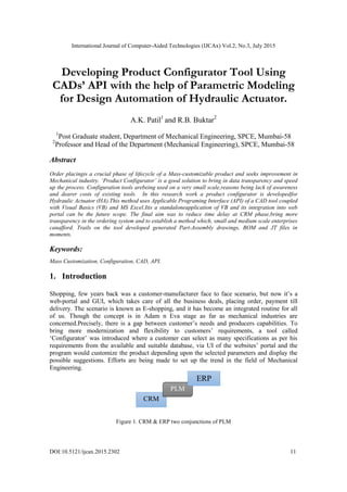
  • 1. International Journal of Computer-Aided Technologies (IJCAx) Vol.2, No.3, July 2015 DOI:10.5121/ijcax.2015.2302 11 Developing Product Configurator Tool Using CADs’ API with the help of Parametric Modeling for Design Automation of Hydraulic Actuator. A.K. Patil1 and R.B. Buktar2 1 Post Graduate student, Department of Mechanical Engineering, SPCE, Mumbai-58 2 Professor and Head of the Department (Mechanical Engineering), SPCE, Mumbai-58 Abstract Order placingis a crucial phase of lifecycle of a Mass-customizable product and seeks improvement in Mechanical industry. ‘Product Configurator’ is a good solution to bring in data transparency and speed up the process. Configuration tools arebeing used on a very small scale,reasons being lack of awareness and dearer costs of existing tools. In this research work a product configurator is developedfor Hydraulic Actuator (HA).This method uses Applicable Programing Interface (API) of a CAD tool coupled with Visual Basics (VB) and MS Excel.Itis a standaloneapplication of VB and its integration into web portal can be the future scope. The final aim was to reduce time delay at CRM phase,bring more transparency in the ordering system and to establish a method which, small and medium scale enterprises canafford. Trails on the tool developed generated Part-Assembly drawings, BOM and JT files in moments. Keywords: Mass Customization, Configuration, CAD, API. 1. Introduction Shopping, few years back was a customer-manufacturer face to face scenario, but now it’s a web-portal and GUI, which takes care of all the business deals, placing order, payment till delivery. The scenario is known as E-shopping, and it has become an integrated routine for all of us. Though the concept is in Adam n Eva stage as far as mechanical industries are concerned.Precisely, there is a gap between customer’s needs and producers capabilities. To bring more modernization and flexibility to customers’ requirements, a tool called ‘Configurator’ was introduced where a customer can select as many specifications as per his requirements from the available and suitable database, via UI of the websites’ portal and the program would customize the product depending upon the selected parameters and display the possible suggestions. Efforts are being made to set up the trend in the field of Mechanical Engineering. Figure 1. CRM & ERP two conjunctions of PLM CRM PLM ERP
  • 2. International Journal of Computer-Aided Technologies (IJCAx) Vol.2, No.3, July 2015 12 Mass customization has led to customer oriented approach and high productivity, hence accelerating the growth of company. In response to this technology, automobile companies have introduced product/sales configurators to automate the order handling process according to the customer requirements.  It is a production strategy focused on the broad provision of personalized products and services, mostly through modularized product/service design, flexible processes, and integration between supply chain members.  For past one decade it has been observed that major developments such as the heavy use of web-based configurators, the emergence of rapid manufacturing technologies, and the implementation of more structured customer-interaction methods are the keys to the success of the Mass Customization.13 Product configurator is a tool used especially for the sale of configurable products and in some cases implemented within an Enterprise Resource Planning (ERP) system to speed-up the lifecycle of a product. It can be seen as the initial phase of PLM. A product configurator signifies the producer’s awareness of customer’s needs and the capability to fulfill these needs with respect to its product offerings. Advantages of using configurator technique are:  Transparency in data sharing and product sales,  Easy and effective way for sales people to negotiate over prices,  Reduce customer’s confusion,  Speed up ERP system and hence reducing delay time in order to speed up production phase,  Impossible combinations or promises can be avoided. Somehow, customer’s perspective is neglected or on other side they are not technically sound at their best. Also, the importance is given to the performance based parameters and aesthetics of a product, nowadays.This is injustice to the technically sound customers and inadequacy in creating awareness in the confused customer. A Configurator can be effectively put into the routine as the remedy. Hydraulic Actuatorsare under consideration here as they are used in industrial process control, employ hydraulic pressure to drive an output member. However, it should be noted that the aim behind this is, merely, to establish the concept of configurator in terms of any one mechanical product; differently any other product would have been considered for the same.  Hydraulic Actuators are used where high speed and large forces are required. The fluid used in hydraulic actuator is highly incompressible so that pressure applied can be transmitted instantaneously to the member attached to it.  Practical application of actuator is however different than the theoretical one. Here few more accessories and supporting instruments are supposed to be attached for the proper functioning of the actuator for the specified purposes.  The product finds its significance in many heavy duty operations as well as in automation field. So this product was selected as the center of this research work. It’s important to understand that though a specific product is selected for this project, the main idea is to establish a method/ develop a tool only. So randomly any product could be selected whose mass customization is possible. There are no special criteria involved in selecting this product here. In short HA is merely a product here to demonstrate the working of
  • 3. International Journal of Computer-Aided Technologies (IJCAx) Vol.2, No.3, July 2015 13 Figure 2. Schematic of Hydraulic Actuator with important parts the new tool i.e. Configurator. Since the project is going to concentrate on HA more, a detailed technical discussion is mentioned ahead about this product’s parameters, interrelations and method of coding them into the main program. 1.1 Concept Initialization and Steps involved: It was decided to coupleCADs’ API and parametric modeling, in Solidworksto develop such a configurator for the producer’s portal. The method uses Visual Basics to generate UI, and which can bring about changes in the CAD model of the component depending upon given inputs by user. Final results expected are part/ assembly drawings, BOM, JT files etc.Solidworks, Visual Basics and MS-Excel arethe toolsutilized in this investigation. All these aspects are discussed further in details, but few steps must be mentioned here:  A database was generated, with the help of HA producing firm.  Basic Modeling was carried out in SOLIDWORKS 2014 interface.  A design process was referred to establish relationship between different parameters of HA, which thereafter was implemented in coding phase.  An API procedure was followed to couple CAD, VB and MS Excel with parametric modeling, to develop the code.  A beta version was release so as to use it as a standalone application.  Final output: A model of Hydraulic Actuator can be displayed, depending upon customization from the customer and subsequently generation of drawings and BOM, which can be processed directly into ERP system for the production department. At present the scope of this study is to develop a standalone application in VB which can be accessed from any PC having Solidworks installed. 2. Related Work 2.1 Literature Survey This projectmainly aims at automation for the mass customization technique in industry. So this study is about techniques which deal with interrelations between various elements or precisely
  • 4. International Journal of Computer-Aided Technologies (IJCAx) Vol.2, No.3, July 2015 14 objects. These objectives can only be achieved with the help of computer based subjects and methods which involve coding and aligned concepts. So it was decided to make a survey of related research work. Initially some steps were proposed like development of a master model, relationships between various dimensions and subassemblies which can modify themselves with the driver dimensions as inputs, inclusion of some design factors like shell design etc. and a User Interface (UI) to control all these activities in the back end. Through this literature survey the author has tried to verify his methodology, adapt new techniques and to modify the existing ones. The general approach which was found in all the papers referred was to put forward the controlling equations, managing the database, solving problems involving configuration, to avoid conflicts, which generally are caused due to mass customization and represent the configurator. P.T. Helo, Q. L. Xu and team members have proposed a vehicle configuration system using Citarasa Ontology, which is a coherent business model which combines the domains of mass customization.1 AlessioTrentin, Elisa Perin and CiprianoForza in their paper discuss testing the positive impact of product configurator use on time performance on manufacturing plants.2 Anders Haug and Lars Hvamb define and compare seven different strategies for the development of product configurators against the generalized one.3 Martin Landherr and EngelbertWestkämper describe the method for integrated product and assembly configuration.4 Dong Yang and Ming Dong present a method of applying constraint satisfaction to resolve product configuration conflicts. 5 BulutAslan, Mark Stevenson and Linda C. Hendry have discussed regarding assessing the fit or alignment between ERP functionality and a Make-To- Order production strategy, which is highly required for the functioning of a configurator.6 JuhaTiihonen, TimoSoininenand team describe a novel configurator prototype that supports configuring, a mass customizable product; which contains a semi-visual modeling tool based on a high-level object- and product structure-oriented modeling language.7 Whereas Dong Yang and Ming Dong present a novel and direct approach to encoding configuration models into the Dynamic Constraint Satisfaction Problems.8 D. Mourtzisa and M. Doukasa describe a novel software architecture that facilitates the ability to visualize and manipulate three-dimensional product design parameters under constraints where the manipulation is performed in real-time, over web, comprising Virtual and Augmented Reality functionalities.9 Jonas Landahl proposes a distinction between limiting and managing product complexity, and stress that these approaches affect internal cost over time differently, using a coding method, but is costly.10 Kenn Steger- Jensena and CarstenSvensson have discussed issues with existing systems for Mass customization and IT solutions possible for the same.11 GüntherSchuha, Stefan Rudolf and Michael Riesenerapropose a methodology which allows companies to determine the "optimal configuration" of a product based on similarities between a new product variant and existing variants. This is exclusively related to the costs framed at the ordering phase, in optimal way.14 C. Forzaa and F. Salvador report a case study of the implementation of a product configuration software in a small manufacturing enterprise; specifically, about the significant benefits that the company enjoyed from the implementation of the software, especially in terms of delivery time and customer relationships.15 Few others have contributed to this field. Literature survey highlights following points:  It is clear that the technology is notnew to the field of Automation whereas on other side it’s not even fully defined, means it has a lot of scope for the improvements and research.  It is also observed that such technologies are being used on a large scale by large scale Industries but the same technology has failed to impress the small and medium scale businesses.
  • 5. International Journal of Computer-Aided Technologies (IJCAx) Vol.2, No.3, July 2015 15  The reasons behind this could be lack of awareness, absence of properly established CRM phase or even inertia towards the conventional methods for the product sales and marketing strategies and order placement and execution.  But the main reason can be related here is cost of the technology. These techniques, no doubt, are based on CAD; so workstation is highly required, no matter a small one or a complete system comprising of multiple machines, it has to be there but the cost of coding and installing these technologies for such small and medium scale firms can surplus the budget. Also there is a major issue with the payback period for the same.  The basic requirements like server, network cables and channels and provision for the DBMS are not cost effective as far as the existing configuration systems or software/ tools are concerned. It should be understood that a skilled programmer is required to develop such tools. 2.2 Industry Survey When it comes to ordering a hydraulic actuator from its manufacturers, there are so many parameters which are supposed to be provided. This is sometimes troublesome for a buyer to provide all such details, due to lack of technical details of the product.Nevertheless, many customers have cognizance of the significance or the selection criteria for the components. But the imbalance between technical knowledge of customers aboutthese parameters and available selection provisions in terms of technical things mainly happens due to telephonic enquiry or mail based enquiry. With the same intensions, when an online industrial survey was carried out, several drawbacks of the ordering systems came into picture. 2.2.1 Problems with Contemporary Systems (HA order placing)  Some HA providers have provision for entering only dimensional and other non-technical details of the product.  Such industriesaccept no technical specifications or details which can play any role in mass customizing such products. The survey carried out explains, the failure in CRM scenario, here, in case of Hydraulic Actuator industry.  No technical details are being exchanged by industries as far as ordering the product is concerned. Even existing configurators do no perform to the expectations. Details of these surveys can be studied through successive discussions.  Manufacturers (under survey) asked for the stroke length and bore diameter, remaining things like material, series of HA, rod size, load to be lifted etc. were simply neglected in the discussions carried out for the market survey.  In other words it was found thatManufacturers assume, conveniently, that the customer is well aware about technical and analytical aspects of HA, which not necessarily holds true always.  There is least involvement of a customer when it comes to make choices in regards with exact requirements. Differently, Manufacturer fails to provide guidelines to a customer when it comes to select various parameters or enter required inputs. This causes perplexed like situations while placing an order, here in case of HA. The general ordering scenario follows following sequence:  The enquiry by customer telephonic/ mail based/ online applications.  Cross enquiry by the manufacturer’s CRM department and asking for technical parameters like bore diameter and stroke length.  Matching of this order with the standard design available with the manufacturer and sending the quotations for the same, based on available combinations only, to the customer.
  • 6. International Journal of Computer-Aided Technologies (IJCAx) Vol.2, No.3, July 2015 16 Software 1 Software 2 New Software Tool Details asked about HA parameters Quotations of available match Enquiry from Customer End Reply with details available CRM: Manufacturer Customer Figure 3. Existing System of order placing  Upon agreement, placing of order by the customer.  Instructions from CRM to form BOM and further process in ERP.  The method generally takes 3-4 days, where the purchasing something feels like a boring process also customer many a times have no single idea about how his end product is going to look like. The tool of configurator tries to minimize this time lag. The same is explained in the following graphics. These consequences have been observed by the authors themselves in reality. This research paper has discussed a method by means of which a cost effective technique or tool (Configurator) can be developed. The main objective thus was to develop a standalone application (with User Interface) that will serve the purpose of easing the process of placing order for a product i.e. HA, which will be able to generate the BOM and Product Drawings ready to incorporate in ERP system and production department. The author will try to reach out and propose an HTML version in extension to this work which is a replica of the web based system. 3. Product Configurator Tool: 3.1. CAD’s API: As discussed earlier the existing configurators use hardcore coding as the backend tool. The feasibility and cost effectiveness of such techniques are few of the major issues. So a midway technique which is easier to understand and cheaper to develop is discussed below: 3.1.1. Applicable Programing Interface (API) Figure 4. Concept of API technique' The idea behind this project was to use two or three software tools that are used by any firm in general, club them so as to obtain a modified version of the software which will take out
  • 7. International Journal of Computer-Aided Technologies (IJCAx) Vol.2, No.3, July 2015 17 benefits from all these clubbed software and will give desired output. The method is called as API. Coding under API varies software-software, but the basic technique is same to connect two or more tools with a UI to get the desired work done. In this investigation, Solidworks API technique is used. This comes for C, C++ and VB, out of which API help menu for VB of Solidworks was extensively used. Basically the technique treats various functions under Solidworks as classes and all instances where these functions are invoked are considered as objects of these classes. The method finds a hierarchical structure arranged with these classes and objects. However the scope of this report is limited to the use of the technique, hence no in depth discussion of the coding language is mentioned. In this study, CAD software i.e. Solidworks, DBMS tool i.e. MS Excel and GUI package i.e. VB are utilized to develop ‘Configurator’. Mainly such kind of application is useful by sales personnel to get on spot orders or to demonstrate the use of this tool. In later part it is discussed about how to convert this standalone system into an HTML code so that the same can be accessed form web by any customer. 3.1.2. Selection of tools, techniques and Pre-requisite  The database generation was a big issue, though the study is to establish a method only. So another survey was conducted in which a detailed data (part lists and a wide database) regarding HA was made available by a company producing HA. In other case if the data was not available, one would have to generate the data using standard design procedures for complete HA.MS Excel was used for this purpose as it finds easy integration with both Solidworks as well as VB.  Secondly a strong but user friendly modeling tool, Solidworks, is the heart of this project, where API coding can be done with less complexity when compared with other packages. One more advantage is that the Solidworks can be incorporated with the MS Excel and VB easily via macro creation. Writing, recording and editing API code as per requirement is very much simple in Solidworks environment. One can use other tools also, but their integrality with other two software is a matter of research, on the other hand Solidworks comes with many user friendly operations and easy to understand.  A workstation with a 4GB RAM, installed with at least win7, Solidworks and MS Excel are the basic requirements of this project work. In addition DB is available. The next steps are to find out parametric relationships and develop appropriate method to develop configurator. Solidworks for modeling MS Excel for Data-Base Visual Basics for (UI) OUTPUT Figure 5. Flow of data through tools selected
  • 8. International Journal of Computer-Aided Technologies (IJCAx) Vol.2, No.3, July 2015 18 3.1.3. Modeling As discussed earlier a master model is required to provide base for rebuilding various configurations. From the data available a random configuration was selected and separate parts and ultimately assembly of HA were modeled in Solidworks environment. Each dimension was named separately so as to use the tags in parametric modeling. Using these model further iterationswas carried out, as mentioned ahead. Few models,assembly are as below.There aretotally 56 no. of major dimensions involved as far as a configuration is concerned. Remaining parametric relations took effect after design and rework stage, the same is discussed in subsequent section. Solidworks 2014 was used for the modeling purpose. Individual parts were modeled first with all required tags and then assembly was done. The extension possessed by parts is .sldprt and that by assembly file is .sldasm. It must be mentioned that in order to work this assembly properly, all the parts and assembly files should be maintained in a same folder/ location. The same is valid for any no. of assembly is as below.Minor changes were considered for the missing dimension links, but as far as the scope of the research is concerned, it remains valid. 3.1.4. Database Management (DBM) There are some 9 different series available on AH’s website. Two of them were selected for this study. Even with these two, for these six basic parts, there is huge dataavailable, which needed to be arranged properly, and this was done using MS Excel. This approach is useful to determine no. of configurations and organize part dimensions properly. A Sample table is shown below for just one part. Bore Diameter Base Plate Dimensions (inch) A B C 2 2.38 0.5 0.25 3 3.38 0.59 0.25 4 4.5 0.75 0.38 5 5.56 0.88 0.38 6 6.75 1 0.38 7 8 1 0.38 8 9 1 0.38 Table 1. A sample database Figure 7. Base Plate (Basic Dimensions) Figure 6. Exploded view of HA assembly with part names
  • 9. International Journal of Computer-Aided Technologies (IJCAx) Vol.2, No.3, July 2015 19 It must be mentioned that apart from these three basic dimensions used, few other will be in picture when parametric modeling will be introduced. 3.2. Design, Calculations and Parametric Modeling The concept of mass customization using configurator tools available, works on the basis of dynamic selection and modeling. This involves conflict solving tools and coding to prevent impossible combinations. This study work has tried to by-pass this approach and keeps these things in semi dynamic state. For this few calculations were studies from HA design and parametric modeling was applied, the same is discussed in brief: 3.2.1.Design:  Range of working pressure: 2500psi, 3000psi  Material of cylinder: Stainless Steel ( = 20000 psi)  Load to be lifted (varying)  Stroke Length/ Elevation in terms of lift Depending upon the inputs, a range of cylinder thickness and Bore diameter is calculated. Using DB form AH and few calculations following thickness was calculated and rounded up to standard thickness.  Desired Bore Diameter = 4 Pr Load essure     Select nearest Standard Bore Diameter (BD)  Cylinder wall thickness =    2 1 ((0.5 ( Pr ) (0.25 )) 2 ) 2 2 ( (( Pr ) / 2)) essure Diameter essure             12  Select suitable rod diameter from available DB Bore Diameter (inch) 2 3 4 5 6 7 8 Wall thickness (inch) 2500 psi 0.134 0.2008 0.2678 0.3347 - - - 3000 psi - 0.2447 0.3263 0.4079 0.4895 0.5710 0.6526 All these design criteria were incorporated during formation of parametric relations. 3.2.2.Parametric Relations: The configurator will be used under circumstances where mass customization comes into picture; so ultimately, parametric relationships will take part into process so that dynamic changes to the model can be imparted. There are many parameters involved when it comes to an assembly and as far as mass customization is concerned there has to be a large amount of data to be considered for the multiple configurations. And this is the reason the project is titled using these keywords, ‘CAD’s API, parametric modeling and design’. This was the crucial task. As it was discussed earlier that the existing configurators use DBMS for the dynamic assignment, it takes lot of efforts and systematic coding. The author is proposing a parallel method in this study where Parametric Relations (PR)will control the Table 2. Minimum shell thickness based on Bore diameter and pressure series available
  • 10. International Journal of Computer-Aided Technologies (IJCAx) Vol.2, No.3, July 2015 20 Figure 8. Parametric drafting for piston menu (Solidworks) modeling phase, i.e. Parametric Modeling (PM). Apart from the design inputs mentioned above there are two major constraints which can affect the configuration process.  Desired Stroke length by the customer  Infinite number of combinations of various components depending upon the nature of duty imposed To overcome this problem it was decided to establish relations between various parameters like inputs from user and various dimensions of the parts. All such relations can be used in the geometry itself so that there will be two or three driving inputs and rest all are driven parameters. If one looks at the DB, it seems quite difficult task, but the method of API associated with Solidworks has made it simple, the same is discussed in detail in later part. This can be implemented during both modeling and API phases. A sample PM is elaborated through an example below: It can be seen that there is hierarchy involved as far as dependency of various dimensions is concerned. So logically, if such dependencies can be mapped for the complete assembly it will be helpful for the semi-dynamic changes to occur in the desired configuration. In this light dimensions were categorized in following types and hierarchy order was decided. The major problem involved was that the DB was only thing available, the relationships or the judgments for the combinations of the parts were not mentioned or available, few of them were derived from designed criteria, few were calculated. In this study there are more than 50 such parametric relations derived or available. It must be mentioned that a few instances minor assumptions were made, which no doubt, are in-line with the database available. After putting them in the hierarchy format the next step is to implement Configuration Techniques.
  • 11. International Journal of Computer-Aided Technologies (IJCAx) Vol.2, No.3, July 2015 21 3.3. Configuration Techniques: Since it’s a kind of substitution for the existing program based method being derived, there were few trial and errors involved. The same efforts are discussed in the form of techniques here; there can be multiple methods, but these two, being aware of their advantages over other, were specifically targeted and used to develop the desired technique.It is to recall that the major tools used are Solidworks, MS Excel and VB. 3.3.1.Technique 1: Design Tables There is a method available in Solidworks where one can create multiple models using a same master model. The technique takes shape from Design tables. Design table is a systematic arrangement of DB, in other words it is a matrix which controls the modeling of a part or the assembly, dynamically. The table is formed using MS Excel. The same can be auto generated or can be imported from the external file. There are syntaxes to be followed and then parameters can be inserted in this file. One more advantage is that one can add these PR directly in the cells. The technique is to implement at the components’ level and then at the assembly level. This will add a number of configurations in the component file itself, there will be a tag generated for each configuration in the design table. Now these tags need to be arranged in the design table associated with the assembly. Once they are arranged, a number of configurations get added to the assembly tree. These are the predefined models which get activated using same master model upon invoking. Design table and configuration tree is shown in the images. Direct Input Dimensions Change with Driver Dimensions directly Change with Driven Dimensions Designed Parameters Depend upon Direct Inputs Dimensions with Constant Value Figure 9. Arrangement of dimensions as controlling parameters in hierarchy
  • 12. International Journal of Computer-Aided Technologies (IJCAx) Vol.2, No.3, July 2015 22 One can add as many numbers of configurations as required. In this method all the parametric equations can be added in the design table only or they can be used in an external Excel file and DB can be created there. But this again leads to a huge data generation and management. This is the simplest method where mass customization of model can be done. This is half way done. But the important half portion required i.e. invoking a particular configuration from the design table has no known way except selecting them manually. Initially, author had a plan of writing an API code for this method but later on it was understood that the code as well as the method, hereafter becomes complicated and may bring in more complexities in terms of coding. So this method was stopped being studied for the desired tool. 3.3.2.Technique 2: Integration of Solidworks and VB &MS Excel using API Almost all software with macro generation ability has some provision for API coding. Here in this study Solidworks was selected because it is a very strong tool for API writing and automating things the way user desires. Help menu of Solidworks provides detailed information regarding API code writing using VB. This study has used Solidworks for parametric modeling as well as API writing to integrate it with VB and DBM can be done using MS Excel. Consider following block diagram: Design Table for: Piston B@Sketch1 A@Sketch1 BD@Sketch1 $COLOR $DESCRIPTION $PARTNUMBER Default 1.5 0.375 0.9985 15651299 Default $D pistnB2R1S2 1.5 0.3755 0.9985 15651299 Default $C pistnB2R1S4 1.5 0.3755 0.9985 15651299 Default $C pistnB3R1.25S6 1.75 0.5005 1.4985 15651299 Default $C pistnB3R1.5S6 1.75 0.5005 1.4985 15651299 Default $C pistnB3R2S12 1.00 0.5005 1.4985 15651299 Default $C pistnB4R1.5S10 1.75 0.6255 1.9985 15651299 Default $C pistnB4R2S12 1.75 0.6255 1.9985 15651299 Default $C pistnB4R2.5S12 1.75 0.6255 1.9985 15651299 Default $C pistnB5R2S12 1.25 0.6255 2.4985 15651299 Default $C pistnB5R2S14 1.25 0.6255 2.4985 15651299 Default $C pistnB5R2S16 1.25 0.6255 2.4985 15651299 Default $C pistnB5R2S18 1.25 0.6255 2.4985 15651299 Default $C pistnB5R2S20 1.25 0.6255 2.4985 15651299 Default $C pistnB5R2S22 1.25 0.6255 2.4985 15651299 Default $C
  • 13. International Journal of Computer-Aided Technologies (IJCAx) Vol.2, No.3, July 2015 23 Solidworks Interface [Master Model integrated with Parametric Modeling] User Interface (UI) Asks for inputs like Load, Pressure Series, Stroke length Output Image JT file Part Drawings Assembly Drawings BOM API Code Figure 10.Framework of Configurator components and their functions So there are three main phases in which this method works. Third phase gives the desired output and can be extended to a number of other applications as per requirements. API code connects first and third phases to second one. There is two way communication between first and second whereas second to third is just one way. a. Unlike the Method 1, this method takes help of parametric modeling. All the relations between various dimensions and variable or other inputs are embedded in the model itself. This was one of the most crucial jobs to embed these relationships into model. Almost 50-60 relations and conditional statements are added in the master model. For this the tags given to the parameters were used. This could be possible only because of Solidworks environment where conditional statements and PR can be incorporated easily and with much more freedom. b. Once it is done a model with capability to change its dimensions, for all parts and alternately for the assembly, keeping physical relations between these parts intact. Now there are few parameters, 5 in this case study, viz. Bore Diameter, Stroke Length, Rod Diameter, Material and Load to be lifted are kept variables. In other words these are driver parameters. c. Next important work is to form a UI; this can be done easily using VB. Now the UI and Master Model have to be connected using an API code. This code can be generated using macro recording facility as well as one can write it also. In this study the author has developed such a code using macro recording and adding new code method to develop final API code. The code takes help of IDoc2 method available with Solidworks API. A basic version of VB is sufficient to incorporate this code in the UI. d. After few iterations of debugging the code runs very well and desired changes do occur perfectly in the model hence the method is confirmed.
  • 14. International Journal of Computer-Aided Technologies (IJCAx) Vol.2, No.3, July 2015 24 3.3.2.1. PM of HA: A sample PM is shown in the figure below. In the course to add these PR in the model, ‘IF’ statement is used extensively, as there are many conditional statements derived so as to match the perfect combinations. Many other are simply equations that are also added in the same way. It must be mentioned that the constrain satisfaction approach is very much important as adding few equations or conditional statement where various parameters are involved differently, can cause geometry errors which in turns stops the auto rebuilding of the model, causing error at the backend, failing the configurator.One more important aspect is as per thehierarchy mentioned earlier; some PR should be embedded in the component file only, whereas driver PR should be implemented in the assembly file. Figure 11.Solidworks interface to incorporate parametric relations into model 3.2.2.2 VB and UI- Integration through API This is the nerve of the configurator tool. As mentioned above, the code can be written as per the API syntax mentioned in Solidworks Help menu or from Solidworks website, also major work can be saved by recording macro and generating code from that stage. Various codes were generated for specific tasks like editing the driver dimension, saving the file and overlapping the existing one, Saving JPEG, Drawing format of file, e-Drawing of the solid etc., these codes are edited and rearranged in the VB coding window. These codes do have specific tags for the edited parameters or save as path/ directory or method etc. VB standalone application will accept values from user and will transfer it to these codes in the backend. Upon auto rebuilding the assembly will incorporate the changes as per the parameters provided. Similarly, upon clicking provided tab, the tool will save the documents in the desired format, especially, e-Drawings, part and assembly drawings and BOM. A sample code is shown in the form of Image.
  • 15. International Journal of Computer-Aided Technologies (IJCAx) Vol.2, No.3, July 2015 25 UI is not mentioned or described here as it is developer’s choice to decorate or arrange the VB standalone application. In this case it was only for accepting few inputs and generates several output files. 4. Results and Future Scope The configurator was tested for two series of HA viz. 2500 psi and 3000 psi and the results obtained were satisfactory. Hence this can prove a low cost and simple tool for small and medium scale industries. Depending upon requirements this UI can be changed and betterment can be brought about. There is a limitation of current investigation that it is a standalone application and can operate on a system where Solidworks is installed. But in the future scope this application can be used as a web based configurator tool also. One way of doing this is convert the standalone form into an HTML page and access the same, but this will again require Solidworks running on the machine. Other way of doing this is to write the same code in .Net environment. It’s possible then to access the same configurator from webpage. One more requirement for this kind of method is installed application of Solidworks on some server which will be in the service continuously. One benefit of this method is such a server can be provided like cloud based system, where company does not require buying the server for its own and not even Solidworks. The scope of this study was kept restricted to the standalone system only which can be used by sales representatives to demonstrate or to accept orders from customer’s doors. The later method would have resulted into out of scope research work, which requires Computer Engineering skills. The suggested future work for the same work is first method where this standalone application can be converted into HTML page. No doubt this application will make the make to order process much comfortable. 5. References: [1] P.T. Helo, Q.L. Xu, S.J. Kyllo¨nen, R.J. Jiao, Integrated Vehicle Configuration System-Connecting the domains of mass customization, Elsevier, Computers in Industry 61 (2010) 44–52, July 2009. [2] AlessioTrentin, Elisa Perin, CiprianoForza, Overcoming the customization-responsiveness squeeze by using product configurators: Beyond anecdotal evidence, Computers in Industry 62 (2011) 260– 268, Elsevier, September 2010. [3] Anders Haug, Lars Hvamb, NielsHenrik Mortensen, Definition and evaluation of product configurator development strategies, Computers in Industry 63 (2012) 471–481, Elsevier, February 2012. [4] Martin Landherr, EngelbertWestkämper, Integrated Product and Assembly Configuration Using Systematic Modularization and Flexible Integration, Variety Management in Manufacturing. Proceedings of the 47th CIRP Conference on Manufacturing Systems, Procedia CIRP 17 (2014) 260 – 265, Elsevier. [5] Dong Yang, Ming Dong, A constraint satisfaction approach to resolving product configuration conflicts, Advanced Engineering Informatics 26 (2012) 592–602, Elsevier, March 2012. [6] BulutAslan, Mark Stevenson, Linda C. Hendry, Enterprise Resource Planning systems: An assessment of applicability to Make-To-Order companies, Computers in Industry 63 (2012) 692– 705, Elsevier, May 2012. [7] JuhaTiihonen, TimoSoininen, IlkkaNiemelä, ReijoSulonen, A Practical Tool For Mass-Customizing Configurable Products, International Conference On Engineering Design, ICED 03 Stockholm, August 19-21, 2003.
  • 16. International Journal of Computer-Aided Technologies (IJCAx) Vol.2, No.3, July 2015 26 [8] Dong Yang, Ming Dong, Xiao-Kun Chang, A dynamic constraint satisfaction approach for configuring structural products under mass customization, Engineering Applications of Artificial Intelligence 25 (2012) 1723–1737, July 2012. [9] D. Mourtzisa, M. Doukasa, A Web-based Platform for Customer Integration in the Decentralized Manufacturing of Personalized Products, 45th CIRP Conference on Manufacturing Systems 2012, Procedia CIRP 3 ( 2012 ) 209 – 214, Elsevier. [10] Jonas Landahl, Dag Bergsjö, Hans Johannesson, Future Alternatives for Automotive Configuration Management, Conference on Systems Engineering Research (CSER 2014), Procedia Computer Science 28 (2014) 103 – 110, Elsevier, March 2014. [11] Kenn Steger-Jensena, CarstenSvensson, Issues of mass customization and supporting IT-solutions, Computers in Industry 54 (2004) 83–103, Elsevier, July 2003. [12] Sumitshrivastva_blogspot_in_2012_09_design_calculation_analysis_Mechanical Guru’s blog [13] Flavio S. Fogliatto, Giovani J.C. daSilveira, Denis Borenstein, The mass customization decade: An updated review of the literature, Int. J. Production Economics 138 (2012) 14–25. [14] GüntherSchuha, Stefan Rudolf a, Michael Riesenera, Similarity-based Product Configuration, Science Direct, Procedia CIRP 17 (2014) 290 – 295. [15] C. Forzaa and F. Salvador, Product configuration and inter-firm co-ordination: an innovative solution from a small manufacturing enterprise, Computers in Industry 49 (2002) 37–46. ACKNOWLEDGEMENT I thank the God Almighty for his blessings and all the wisdom he has blessed me with. I would like to express my deepest gratitude to my guide and Head of the department, Dr. R. B. Buktar, who has the attitude and the substance of a true academician. He continually and convincingly conveyed and supported a spirit of exploration in regard to pursuing my goals. Without his constant motivation and persistent inputs this dissertation would not have been possible. I thank my parents for their support and efforts with which they stand by me all the time. I thank all my colleagues and friends for all the support offered at various instances which led to completion of this project. Finally I would like to all members at SPCE who have helped me directly or indirectly to complete this project.
  • 17. International Journal of Computer-Aided Technologies (IJCAx) Vol.2, No.3, July 2015 27 Authors: Mr. Aniket K. Patil Post Graduate Student (M. Tech in Machine Design) Department of Mechanical Engineering Sardar Patel College of Engineering, Mumbai-58 Dr. Rajesh B. Buktar Ph. D. in Technology Prof.& Head of Department, Department of Mechanical Engineering Sardar Patel College of Engineering, Mumbai-58