Challenges in Assessing Single Event Upset Impact on Processor Systems
Design Test Methodology Motorola C-5e DCP Using Cadence Incisive
1. Design for Test Methodology
Case Study for Motorola C-5e DCP
Using the Cadence Incisive
Accelerator/Emulator
Justin Hernandez
SA837/CORP/GSG
ZAS37/justin.hernandez@motorola.com
Philip Giangarra
RU433/SPS/NCSG
MA07/philip.giangarra@motorola.com
ABSTRACT
VLSI designs, which consist of partial scan and BIST
(built-in self test), often give rise to an area of circuitry
that can only be verified after fabrication by functional
manufacturing test patterns. The faultgrading process
quantifies the ability of the entire test suite to detect a
manufacturing fault in the circuit. Advances in
technology and the ever-increasing size and complexity
of VLSI circuits have proven the task of obtaining a
faultgrading measurement within an acceptable period of
time and level of cost a challenging one. This paper
describes a faultgrading methodology that makes use of
the Cadence Incisive accelerator/emulator in order to
faultgrade the manufacturing test suite used for the
Motorola C-Port c5-dcp (digital communications
processor). The Incisive accelerator/emulator provided
the flexibility to faultgrade the c5-dcp in a period of 6
weeks, in comparison to the more than 4,000 years it
would take to perform the same task on a software
simulator.
INTRODUCTION
This paper describes the manufacturing test
methodology used for the Motorola C-Port c5-dcp,
presenting the issues faced, how solutions were created
and results.
BACKGROUND
Faultgrading, FG, is a metric which measures the ability
of a test suite1
, T, to detect a manufacturing fault in a
circuit. The faultgrade process may be carried out in
many different ways; the method that is discussed in this
1
Typically a suite of more than one test.
paper is a serial fault simulation. This process involves
taking a fault-free circuit, C, and modifying it by
inserting a single stuck at fault, f, thus creating Cf. Then
the test suite is simulated on the circuit, Cf, to ascertain
the test suite’s ability to detect the stuck at fault in the
circuit. This process is repeated for a set of faults, F, in
order to obtain a measurement of the number of detected
faults, D. The faultgrading metric is calculated by the
ratio of the total number of detected faults to the total
number of inserted faults.
FGT = D / F
The faultgrading metric is extremely valuable because it
allows us to quantify the quality of the manufacturing
test suite, which is directly related to the quality of the
shipped product.
MANUFACTURING TEST METHODOLOGY
The c5-dcp was designed using a mixture of standard
cell blocks, full custom blocks and generated logic (for
regular structures such as memories). The standard cell
logic contained full scan flip-flops and scan chains; most
memories (RAMs, CAMs and WCSs) contained BIST.
The full custom logic had a nominal amount of extra test
logic added. Therefore, the manufacturing test
methodology that was used consisted of ATPG
(automatic test pattern generation) and functional
manufacturing test patterns. The c5-dcp has
approximately 70 percent of the design covered by scan
and BIST; the remaining 30 of the design was covered
by functional manufacturing test patterns.
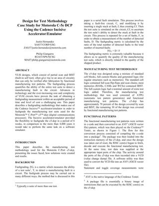
FUNCTIONAL PATTERNS
The functional manufacturing test patterns were written
in c-code and then converted to an AVF2
(ASCII vector
file) pattern, which was then played on the Credence
Tester, as shown in Figure 1. The flow for this
conversion process consisted of compiling the c-code
into a package3
. The package was then loaded into the
instruction memory of the c5-dcp, and once the design
was taken out of reset, the RISC core(s) began to fetch,
decode and execute the functional manufacturing test.
At the same time, test data was supplied at the
appropriate input ports of the chip. The activity around
the ports of the c5-dcp was then recorded into a VCD
(value change dump) file. A software utility was then
used to convert the VCD file into an AVF (ASCII vector
file).
Statement and toggle coverage measurements were
2
AVF is the native language of the Credence Tester.
3
A package file is essentially a binary image of
instructions that can be executed by the RISC core(s) on
the c5-dcp.
2. performed; the results were used to direct the functional
manufacturing test writing team to either modify tests
from the existing test suite or to add new tests.
Figure 1: Functional Manufacturing Test Pattern
Flow
ISSUES FACED AND SOLUTIONS CREATED
The coverage of the ATPG vectors for the partial scan
and BIST were known. However, the coverage of the
functional manufacturing test patterns was unknown.
Hence, there was a need to determine the quality of the
suite of manufacturing test patterns in order to know
how good the patterns were at detecting manufacturing
faults in the c5-dcp.
NEED FOR FAULTGRADE
The intended purpose of the manufacturing test suite
was to run on the pre-packaged parts. The expectation
was that the test suite would remove the defective parts
before they reached the packaging stage of the
manufacturing process, hence reducing the overall cost
of test. However, the early samples of packaged parts
from the manufacturing plant were failing system-level
tests. This implied that the manufacturing test suite was
inadequate for removing all defective parts,
demonstrating a need to faultgrade the manufacturing
test suite in order to identify where the deficiencies lied.
SOFTWARE FAULTGRADING SOLUTION
Originally, the Cadence Verifault-XL concurrent
fault software was chosen to faultgrade the suite of
manufacturing patterns. However, after running a small
manufacturing test case on a large Sun server, it became
immediately apparent that this would not be fast enough.
From the test case, we projected a total time of over
12,000 years (for a single computer).
EMULATION FAULTGRADING SOLUTION
The Cadence Incisive accelerator/emulator was chosen
to perform the task of faultgrading the manufacturing
test suite on the c5-dcp design. This involved the
emulator behaving like a tester. However, the emulator
provided the flexibility to modify the circuit to insert a
single stuck at fault and then simulate the manufacturing
test suite to determine if the fault was detected. In
addition to this, the Cadence software provided the
capability to automate the faultgrading process. The
most elegant feature of the emulation solution was the
emulator’s capability to achieve simulation speeds in the
order of tens of thousands of cycles per second. In
comparison, a software simulation of the c5-dcp gate-
level netlist could only reach tens of cycles per second.
FAULT DICTIONARY CREATION
Before the c5-dcp design could be faultgraded, a fault
dictionary needed to be created. The fault dictionary
describes the stuck-at-one and stuck-at-zero condition
for each and every net in the circuit under test. The tool
chosen to perform fault dictionary creation was
Fastscan by Mentor Graphics. Fastscan classified each
of the faults into one of several categories. The
categories were then used to indicate:
- if the fault was detected by a scan chain
- if the fault was untestable4
- if the fault was equivalent to another fault in
the fault dictionary
The fault dictionary was then collapsed, which is the
process of removing all of the functionally equivalent
faults from the total set of faults. For faultgrading it is
sufficient to consider only one representative fault from
every equivalent set of faults. In addition to this, the
4
Fastscan defines an untestable fault as a fault that
cannot result in a functional failure.
C-Code
CST
Compiler
Package
Test
Generation
VCD AVF
Conversion
Program
Credence
Tester
3. Fastscan C5 Netlist
100% Fault Dictionary, FD ct
Fault Dictionary, FD sm
Filter ATPG/BIST
ATPG and BIST
Detected Faults
Remaining Faults
for Faultgrading
Faultgrade on
Incisive Accel.
Random Sample
Figure 3: Algorithm for Optimum Pattern Order
If(StatementCoverageB>(1+ρ/α)*StatementCoverageA)
Faultgradeorder=PatternBfirst,PatternAsecond;
Else
Faultgradeorder=PatternAfirst,PatternBsecond.
faults that were classified as untestable were also
removed, thus creating a collapsed and testable fault
dictionary, FDct.
SAMPLING
Due to the large size of the c5-dcp circuit, it was
prohibitive with respect to both time and cost to
faultgrade the entire fault dictionary, FDct. Hence, a
random fault sampling technique [1] was used to create
a smaller fault dictionary, FDsm, which could be
faultgraded in an acceptable period of time. However,
sampling creates a tradeoff between the accuracy of the
faultgrade metric and the cost to perform the faultgrade
measurement.
Once the fault dictionary, FDct, was created and the
maximum acceptable error was known, the size of the
random fault sample dictionary, m, could be calculated b
equation 2 in Appendix A: Sampling of Fault
Dictionary. Since the random fault sample dictionary,
FDsm, still contained the Fastscan classifications, the
faults that were detected by partial scan were
immediately considered as being detected by the
manufacturing test suite. Similarly, the faults in the
random sample covered by BIST were also considered
as being detected, thus further reducing the simulation
time needed to faultgrade the functional patterns in the
manufacturing test suite. As shown by Figure 2, the
remaining faults in the random fault sample dictionary,
FDsm, were simulated on the Incisive
accelerator/emulator to establish what additional
coverage was gained, thus giving the final faultgrading
metric.
Figure 2: Random Fault Sample Dictionary
Generation Flow
OPTIMUM PATTERN ORDER
Once the random fault sample dictionary, FDsm, had
been created, the faults detected by ATPG and BIST
were immediately categorized as detected by the
manufacturing test suite. The remaining faults in FDsm
were then faultgraded against the functional patterns in
the manufacturing test suite on the Incisive
accelerator/emulator, shown in Figure 3.
The order in which the functional manufacturing
patterns are faultgraded directly impacts the total
amount of time needed. Appendix B: Optimum
Faultgrade Pattern Order demonstrates that the optimum
pattern order involves a tradeoff between the length of
the pattern and the number of faults detected by that
pattern. However, since the number of faults detected by
a pattern is unknown
until after the faultgrade, determining the optimum order
involves predicting the future. Fortunately, statement
coverage results obtained from simulating the patterns
on the RTL assists in predicting the expected number of
faults to be caught.
In general, if two patterns, A and B, are such that pattern
A is larger than pattern B, if the statement coverage
indicates that pattern A has higher statement coverage
than pattern B, then pattern A should be faultgraded
first.
Figure 4: Serial Faultgrade Flow
Faultgrade Next Pattern
Get Next Fault
Any Remaining Patterns
to Faultgrade?
Yes
No
Metric
Faultgrade
Emulate Pattern
on c5 Design
Insert Fault
Fault Dictionary, FD
Remove Detected Faults and
sm
4. However, the order should be reversed when the
statement coverage of pattern B is greater than the
factor, which pattern B is larger than pattern A. This
algorithm is shown in Figure 4.
Note that this algorithm should be use only as a general
rule of thumb. The error that is involved with this
algorithm is specified in Appendix B.
RESULTS
The Incisive accelerator/emulator proved itself as being
more than capable of faultgrading the manufacturing test
suite on the c5-dcp within an acceptable period of time
and at a satisfactory cost.
CYCLES USED
The faultgrading of the manufacturing test suite of the
c5-dcp required 6 weeks of access to an Incisive
accelerator/emulator. This equated to over 250 billion
simulation cycles. In comparison, it would have taken
more than 4,000 years to reach this volume of software
simulation cycles to faultgrade the manufacturing test
suite on the c5-dcp gate-level netlist.
LESSONS LEARNED ON CUSTOM
STRUCTURES
The c5-dcp consisted of custom and semi-custom
structures. The advantages of designing with custom
structures were that the silicon area was greatly reduced
and the maximum speed of the circuit was increased.
However, since there was no scan logic included in the
custom structure, automatic test pattern generation was
not possible, thus creating the need for functional
manufacturing test patterns and the need for faultgrading
these patterns.
The development of the functional manufacturing
patterns proved to be the most challenging element of
the manufacturing test methodology. This was primarily
due to the functional manufacturing test patterns being
written very late in the design flow, at which point it
was very difficult to change the design5
. Hence, the
lesson learned was that when custom structures are used
in a design, additional engineering resources need to be
employed very early on in the design flow so that the
custom structure can be tested with ease by scan, BIST
or functional manufacturing test patterns.
5
In this context, the term “late in the design flow” refers
to a period after the first tape-out revision of the c5-dcp.
CONCLUSION
This paper has described the manufacturing test
methodology used for the c5-dcp, presenting the issues
faced, how solutions were created and the results. Since
the c5-dcp design was covered 70 percent by partial
scan and partial memory BIST, this created the need for
functional manufacturing test patterns, which created the
need to faultgrade the manufacturing test suite to
quantitatively measure the test suite’s ability to detect a
defect in the manufactured part. We found that the
emulation solution, which employed the use of the
Incisive accelerator/emulator, provided the flexibility to
faultgrade the c5-dcp in a period of 6 weeks. In
comparison, it would have taken over 4,000 years to
perform the same task on a software simulator. Other
issues such as the creation and sampling of the fault
dictionary and the optimum order to faultgrade the
functional test patterns were also explored. The results
showed that the Incisive accelerator/emulator proved
itself as being more than capable of faultgrading the
manufacturing test suite on the c5-dcp within an
acceptable period of time and at a satisfactory cost. In
addition to this, we found that if the functional
manufacturing test patterns had been created earlier in
the design flow, it would have become obvious that
additional manufacturing test techniques such as scan
and BIST were needed.
ACKNOWLEDGEMENTS
The authors thank the Motorola VLSI design team in
Mansfield, Mass. and the Cadence support team in
Lowell, Mass. Philip Giangarra was responsible for
uncovering the Incisive accelerator/emulator’s potential
to solve the problem of faultgrading the manufacturing
test suite on the c5-dcp design. He was the primary
contributor to the development of the automation
software, which unleashed the capability of the Incisive
accelerator/emulator to automate the faultgrading
process. David Sallard and Jason Drew from Cadence
provided support throughout the c5-dcp faultgrade
project.
REFERENCES
[1] “Digital Systems Testing and Testable
Design,” Miron Abramovici, Melvin A. Breuer,
Arthur D. Friedman.
5. TRADEMARKS
Motorola is a registered trademark of Motorola Inc.
C-5, C-5e and C-Port are all registered trademarks of C-
Port Corporation.
Verifault-XL, Incisive and Incisive accelerator/emulator
are all trademarks of Cadence Design Systems, Inc.
Design Compiler is a registered trademark of Synopsys
Inc.
Fastscan is a registered trademark of Mentor Graphics.
Credence is a registered trademark of Credence Systems
Corporation.
APPENDIX A: SAMPLING OF FAULT
DICTIONARY
When taking a sample from the fault dictionary, the
maximum error, emax, of the measured faultgrade metric,
F, is dependent on the size of the collapsed netlist, M,
the size of the random sample taken, m, and the
measured faultgrade metric, F.
Definitions
Equation 1: emax = 3√( ( F.( 1-F ).( 1 – m/M ) ) / m )
Due to the F.(1-F) factor that is in the numerator, this
ensures that emax is at a maximum when F=0.5. Hence,
if the size of the collapsed netlist, M, is known, and the
maximum acceptable error of the faultgrade, emax, is
known, then if we let F=0.5. The sample size may be
computed by:
Let F=0.5
emax = 3√( ( 0.5.( 1-0.5 ).( 1 – m/M ) ) / m )
emax
2
/ 9 = ( ( 0.25 ).( 1 – m/M ) ) / m
emax
2
/ 2.25 = ( 1 – m/M ) / m
M.emax
2
/ 2.25 = ( 1 – m/M ) / ( m/M )
Let s = m/M ( which is the size of the sample as a
percentage of the collapsed netlist )
Let a = M.emax
2
/ 2.25
a.s = 1 – s
s = 1 / ( 1 + a )
s = 1 / ( 1 + ( M.emax
2
/ 2.25 ) )
Equation 2: m = M / ( 1 + ( M.emax
2
/ 2.25 ) )
APPENDIX B: OPTIMUM FAULTGRADE
PATTERN ORDER
This appendix describes the optimum order that patterns
should be faultgraded in:
Definitions
ζ = Number of faults detected from first pass, when
pattern A is run first
ζ′ = Number of faults detected from first pass, when
pattern B is run first
α = Length of pattern A
β = Length of pattern B
γ = Number of faults to be inserted on first pass
ρ = β - α = Number of additional cycles that pattern B
is than pattern A
If pattern A is faultgraded before pattern B then the total
number of cycles, T, needed for faultgrading both
patterns, T, is given by:
Equation 3: T = γ.α + (γ - ζ ).β
Substitute β = α + ρ into Equation 3
T = γ.α + (γ - ζ ).( α + ρ )
T = γ.α + γ.α + γ.ρ - ζ.α - ζ.ρ
T = 2.γ.α - ζ.α + γ.ρ - ζ.ρ
Equation 4: T = α.( 2.γ - ζ ) + γ.ρ - ζ.ρ
If pattern B is faultgraded before pattern A then the total
number of cycles, T¢, needed for faultgrading both
patterns is given by:
Τ′ = γ.β + ( γ - ζ′ ). α
Substitute β = α + ρ
Τ′ = γ.( α + ρ ) + ( γ - ζ′ ).α
Τ′ = α.γ + γ.ρ + α.γ - α.ζ′
Τ′ = 2.α.γ + γ.ρ - α.ζ′
Equation 5: Τ′ = α.( 2.γ - ζ′ ) + γ.ρ
Now let’s create an inequality using Equation 4 and
Equation 5 to determine the number of additional faults
that pattern B needs to detect, ζ′, when pattern B is run
first, in order for the total number of cycles to be less.
Τ′ < T
α.( 2.γ - ζ′ ) + γ.ρ < α.( 2.γ - ζ ) + γ.ρ - ζ.ρ
-α.ζ′ < -α.ζ - ζ.ρ
Equation 6: ζ′ > ζ.(1 + ρ/α)
In order to minimize the total number of cycles needed
to faultgrade patterns A and B, in general pattern A
should always be run before pattern B, unless pattern B
shall detect more faults than the factor which pattern B
is larger than pattern A.
For Example,
α = 10 (length of pattern A)
β = 15 (length of pattern B)
Then,
ρ = β - α = 5 (Number of addition cycles that pattern
B is than pattern A)
Hence,
ζ′ > ζ.(1 + ρ/α)
ζ′ > ζ.(1 + 5/10)
ζ′ > ζ.(1.5)
So, in order to justify running pattern B before pattern
A, pattern B must detect 50 percent more faults than
pattern A on its first pass.
6. In should be noted that this result should only be used as
a rule of thumb because it assumes that the fault is
detected near or at the end of each of the patterns. This
is a significant assumption because the point in the
pattern at which the fault is detected is dependent on a
number of variable factors, which include:
- if the fault will be caught
- the size of the fault dictionary sample
- the stage at which the pattern is run in the
overall faultgrade
- correlation between the remaining faults and
the area of circuitry being targeted by the
pattern
- the nature of the pattern (i.e. register write/read
test pattern vs. a finite state machine test
pattern).