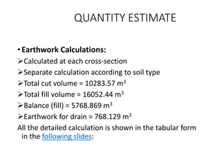
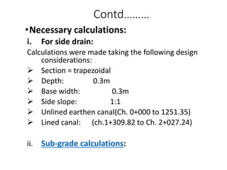
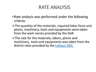
C. Scope
To review the existing study reports, standards and specifications.
Detailed engineering survey of alignment.
Preparation of topographical map.
Study for cross-drainage works and propose suitable drainage
structure.
Preparation of working drawings.
Preparation of quantity and cost estimate.
Preparation of survey and design report
D. Project location
The proposed road is located in the Lalitpur District,
Bagmati Zone, Central Region. The road starts from
Badikhel and ends at Badegaun.
The road runs along Karmanasha River corridor.
The latitude and the longitude of the starting point are
27057’07’’ and 85035’27’’ respectively.
F. Hydrology And Meteorology
Small temporary streams running only during monsoon crosses
the alignment with small discharge.
The project area experiences marked seasonal and specific
climate variation with moderately hot summer and relatively cool
winters. Average temperature is 25oC in summer and 10oC in
winter.
Almost 80% of the rainfall occurs during monsoon which starts
at the middle of the June and continues until the end of August.
METHODOLOGY
DESK STUDY
SOCIAL IMPACT ASSESMENT
FIELD WORK
EQUIPMENT USED FOR SURVEYING
OFFICE WORK
DESK STUDY
The geographical and the topographical maps
were studied and the relevant information
regarding the alignment selection, cross drainage
structures, gradient of the road were discussed.
The strategy for the field study was made
accordingly.
The study team member discussed the related
matters of the project.
SOCIAL IMPACT ASSESMENT
The study identified the following key social issues
for investigation:
Loss of private property and other assets (land,
houses and trees) and compensation modalities for
these losses.
Population displacement.
 EQUIPMENT USED FOR
SURVEYING
Total station
GPS device
Staff
Compass
Measuring tape
Hammer
Communicating Device
Road Classification
As per the NRS 2045, the road project falls on the
category of District Roads.
 A Design speed of 30 km/hr is taken for the
design of geometric parameters of the road.
Design Speed
The Design values are taken as recommended by NRS
2045 as far as practicable
The shoulder width is taken as 1 m considering the
site condition and the utility of the road
Minimum Gradient recommended by NRS (1% for
better drainage) cannot be incorporated considering
the site condition
Horizontal Alignment
 The most suitable horizontal alignment was selected
considering the following factors:
 Short (S)
 Easy (E)
 Safe (S)
 Economical (E)
 Minimum radius for the horizontal curve as
recommended by NRS is 12 m. The minimum radius of
12m is provided at the intersection of existing road
and proposed road.
The extrawidening and transition curves are not
provided owing to low design speed and simplicity in
construction
A maximum of 5 % super elevation is provided at each
horizontal curve.
Superelevation is provided by rotation of pavement
about the center line.
Transition length for super elevation is provided as 5 m
Summit curves are designed considering stopping sight
distance.
Valley curves are designed on the basis of night
visibility
The radius of vertical curve is adopted as large as
possible so that all the factors are satisfied
The least vertical radius taken in design is 1000 m
Cross Section Design
Cross section is designed providing camber of 4% on
carriageway and 5 % on shoulder
For embankment the side slope of 1.5H: 1V and for cut
the side slope of 1H: 1V is adopted
Total pavement thickness of 28 cm is adopted as per
CBR method of design
Gravel is used as the sub-base course
Otta Seal is used as the surface course
Drainage
Longitudinal drain is provided on the cut slope side of the
road
The side slope is 1:1 and longitudinal slope is parallel to the
alignment
Earthen drain is provided from chainage 0+000 to the
chainage of 1+251.35
Stoned masonry drain of thickness 20 cm is provided from the
chainage of 1+309.82 to chainage 2+027.24
Pipe culverts of 60 cm in diameter and total length of
7.5m are provided at 12 sections of the road
They are provided at the lowest point of the vertical
alignment
A minimum depth of 60 cm is provided between the
surface of the pavement and the crown of the pipe
Plan and Profile
• Ch. 0+000-0+200
• Ch. 0+200-0+480
• Ch. 0+480-0+760
• Ch. 0+760-1+040
• Ch. 1+040-1+360
• Ch. 1+360-1+700
• Ch. 1+700-2+027.24
Cross Section
• Ch. 0+000-0+271.50
• Ch. 0+280-0+500
• Ch. 0+511.92-0+680
• Ch. 0+683.87-0+760
• Ch. 0+780-0+920
• Ch. 0+936.71-1+125.89
• Ch. 1+130.75-1+213.66
• Ch.1+220-1+319.59
• Ch.1+320-1+380
• Ch.1+397.04-1+465.09
• Ch.1+480-1+545.77
• Ch.1+560-1+800
• Ch.1+800.91-1+980
• Ch.1+984.58-2+027.24
Typical Pavement
Cross Drainage Structure
ESTIMATE
Quantity Estimate
Calculation of Earthwork
Necessary Calculations
Rate Analysis
BoQ /Cost Estimate
QUANTITY ESTIMATE
•Earthwork Calculations:
Calculated at each cross-section
Separate calculation according to soil type
Total cut volume = 10283.57 m3
Total fill volume = 16052.44 m3
Balance (fill) = 5768.869 m3
Earthwork for drain = 768.129 m3
All the detailed calculation is shown in the tabular form
in the following slides:
Contd………
•Necessary calculations:
i. For side drain:
Calculations were made taking the following design
considerations:
 Section = trapezoidal
 Depth: 0.3m
 Base width: 0.3m
 Side slope: 1:1
 Unlined earthen canal(Ch. 0+000 to 1251.35)
 Lined canal: (ch.1+309.82 to Ch. 2+027.24)
ii. Sub-grade calculations:
RATE ANALYSIS
•Rate analysis was performed under the following
criteria:
The quantity of the materials, required labor force and
plants, machinery, tools and equipments were taken
from the work norms provided by the DoR.
The rate for the materials, labors, plants and
machinery, tools and equipments was taken from the
district rates provided by the Lalitpur DDC.
COST ESTIMATE
• The BoQ was prepared on the basis of the quantity of
work calculated and rate analysis done previously:
• The cost estimate is as below:

Design Aproach.pptx

  • 1.
    C. Scope To reviewthe existing study reports, standards and specifications. Detailed engineering survey of alignment. Preparation of topographical map. Study for cross-drainage works and propose suitable drainage structure.
  • 2.
    Preparation of workingdrawings. Preparation of quantity and cost estimate. Preparation of survey and design report
  • 3.
    D. Project location Theproposed road is located in the Lalitpur District, Bagmati Zone, Central Region. The road starts from Badikhel and ends at Badegaun. The road runs along Karmanasha River corridor. The latitude and the longitude of the starting point are 27057’07’’ and 85035’27’’ respectively.
  • 4.
    F. Hydrology AndMeteorology Small temporary streams running only during monsoon crosses the alignment with small discharge. The project area experiences marked seasonal and specific climate variation with moderately hot summer and relatively cool winters. Average temperature is 25oC in summer and 10oC in winter. Almost 80% of the rainfall occurs during monsoon which starts at the middle of the June and continues until the end of August.
  • 5.
    METHODOLOGY DESK STUDY SOCIAL IMPACTASSESMENT FIELD WORK EQUIPMENT USED FOR SURVEYING OFFICE WORK
  • 6.
    DESK STUDY The geographicaland the topographical maps were studied and the relevant information regarding the alignment selection, cross drainage structures, gradient of the road were discussed. The strategy for the field study was made accordingly. The study team member discussed the related matters of the project.
  • 7.
    SOCIAL IMPACT ASSESMENT Thestudy identified the following key social issues for investigation: Loss of private property and other assets (land, houses and trees) and compensation modalities for these losses. Population displacement.
  • 8.
     EQUIPMENT USEDFOR SURVEYING Total station GPS device Staff Compass Measuring tape Hammer Communicating Device
  • 9.
    Road Classification As perthe NRS 2045, the road project falls on the category of District Roads.
  • 10.
     A Designspeed of 30 km/hr is taken for the design of geometric parameters of the road. Design Speed
  • 11.
    The Design valuesare taken as recommended by NRS 2045 as far as practicable The shoulder width is taken as 1 m considering the site condition and the utility of the road Minimum Gradient recommended by NRS (1% for better drainage) cannot be incorporated considering the site condition
  • 12.
    Horizontal Alignment  Themost suitable horizontal alignment was selected considering the following factors:  Short (S)  Easy (E)  Safe (S)  Economical (E)  Minimum radius for the horizontal curve as recommended by NRS is 12 m. The minimum radius of 12m is provided at the intersection of existing road and proposed road.
  • 13.
    The extrawidening andtransition curves are not provided owing to low design speed and simplicity in construction A maximum of 5 % super elevation is provided at each horizontal curve. Superelevation is provided by rotation of pavement about the center line. Transition length for super elevation is provided as 5 m
  • 14.
    Summit curves aredesigned considering stopping sight distance. Valley curves are designed on the basis of night visibility The radius of vertical curve is adopted as large as possible so that all the factors are satisfied The least vertical radius taken in design is 1000 m
  • 15.
    Cross Section Design Crosssection is designed providing camber of 4% on carriageway and 5 % on shoulder For embankment the side slope of 1.5H: 1V and for cut the side slope of 1H: 1V is adopted Total pavement thickness of 28 cm is adopted as per CBR method of design
  • 16.
    Gravel is usedas the sub-base course Otta Seal is used as the surface course
  • 17.
    Drainage Longitudinal drain isprovided on the cut slope side of the road The side slope is 1:1 and longitudinal slope is parallel to the alignment Earthen drain is provided from chainage 0+000 to the chainage of 1+251.35 Stoned masonry drain of thickness 20 cm is provided from the chainage of 1+309.82 to chainage 2+027.24
  • 18.
    Pipe culverts of60 cm in diameter and total length of 7.5m are provided at 12 sections of the road They are provided at the lowest point of the vertical alignment A minimum depth of 60 cm is provided between the surface of the pavement and the crown of the pipe
  • 19.
    Plan and Profile •Ch. 0+000-0+200 • Ch. 0+200-0+480 • Ch. 0+480-0+760 • Ch. 0+760-1+040 • Ch. 1+040-1+360 • Ch. 1+360-1+700 • Ch. 1+700-2+027.24
  • 20.
    Cross Section • Ch.0+000-0+271.50 • Ch. 0+280-0+500 • Ch. 0+511.92-0+680 • Ch. 0+683.87-0+760 • Ch. 0+780-0+920 • Ch. 0+936.71-1+125.89 • Ch. 1+130.75-1+213.66 • Ch.1+220-1+319.59 • Ch.1+320-1+380 • Ch.1+397.04-1+465.09 • Ch.1+480-1+545.77 • Ch.1+560-1+800 • Ch.1+800.91-1+980 • Ch.1+984.58-2+027.24
  • 21.
  • 22.
    ESTIMATE Quantity Estimate Calculation ofEarthwork Necessary Calculations Rate Analysis BoQ /Cost Estimate
  • 23.
    QUANTITY ESTIMATE •Earthwork Calculations: Calculatedat each cross-section Separate calculation according to soil type Total cut volume = 10283.57 m3 Total fill volume = 16052.44 m3 Balance (fill) = 5768.869 m3 Earthwork for drain = 768.129 m3 All the detailed calculation is shown in the tabular form in the following slides:
  • 24.
    Contd……… •Necessary calculations: i. Forside drain: Calculations were made taking the following design considerations:  Section = trapezoidal  Depth: 0.3m  Base width: 0.3m  Side slope: 1:1  Unlined earthen canal(Ch. 0+000 to 1251.35)  Lined canal: (ch.1+309.82 to Ch. 2+027.24) ii. Sub-grade calculations:
  • 25.
    RATE ANALYSIS •Rate analysiswas performed under the following criteria: The quantity of the materials, required labor force and plants, machinery, tools and equipments were taken from the work norms provided by the DoR. The rate for the materials, labors, plants and machinery, tools and equipments was taken from the district rates provided by the Lalitpur DDC.
  • 26.
    COST ESTIMATE • TheBoQ was prepared on the basis of the quantity of work calculated and rate analysis done previously: • The cost estimate is as below: