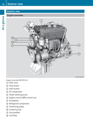
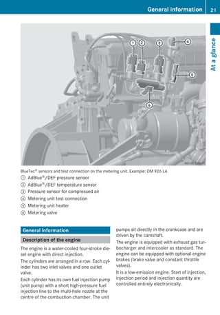
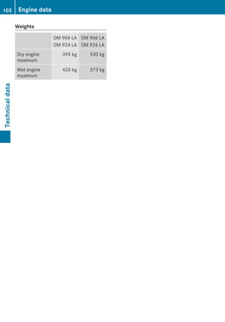
OM 904-926 LA BlueTec®, OM 904-926 LA
Operating Instructions
Symbols
$ Warning
% Environmental note
! Possible vehicle damage
i Tip
X Instructions
YY Continuation symbol
(Y page) Page reference
Welcome to the world of Mercedes-Benz
Familiarise yourself with your engine and read
the Operating Instructions before you use the
engine. This will help you to avoid endanger-
ing yourself or others.
The standard equipment and product descrip-
tion of your engine may vary, depending on
individual specifications. This is described on
the engine data card.
Mercedes-Benz constantly updates its
engines to the state of the art.
Mercedes-Benz reserves the right to make
changes to the following:
Rdesign
Requipment
Rtechnical features
You cannot therefore base any claims on the
data, illustrations or descriptions in this man-
ual.
The manual/instructions are comprised of:
ROperating Instructions
RMaintenance Booklet
Always keep these documents together with
the engine/vehicle/device. These docu-
ments should be passed on to the new owner
if you sell the engine/vehicle/device.
i You can find out about your engine's
important functions in German and English
in the online Owner's Manual at: http://
www.mercedes-benz.de/betriebsanleitun-
gen
The technical documentation team at
Daimler AG wishes you safe and pleasant
motoring.
9265840681 É9265840681ÁËÍ
Index ....................................................... 4
General information .............................. 7
At a glance ........................................... 13
Safety ................................................... 29
Driving mode/working mode ............. 33
Maintenance and care ........................ 45
Notes on maintenance ....................... 59
Decommission and protection ........... 79
Breakdown assistance ....................... 85
Technical data ..................................... 99
Contents 3
A
Adaptation module .............................. 21
AdBlue®/DEF
Components .................................... 19
Consumption ................................... 41
Refuelling ......................................... 42
Replacing the filter ........................... 69
Service product ............................... 54
ADM (FR (drive control) unit) ............. 21
Antifreeze ............................................. 73
B
Bio-diesel fuel
see FAME fatty acid methyl ester fuel
Bleeding the fuel system .................... 86
Bleeding the fuel system manually ... 86
BlueTec®
Exhaust gas aftertreatment ................ 9
Sensors ............................................ 19
BlueTec® exhaust gas aftertreat-
ment
AdBlue® service product .................. 54
Braking
Continuous brake ............................ 40
C
Capacities .......................................... 104
Care products ...................................... 55
Charge current .................................... 37
Checking the fluid level ...................... 34
Cleaning and care
Engine cleaning ................................ 56
High-pressure cleaning .................... 55
Notes on care .................................. 55
Cold-start aid ....................................... 27
Consumption
AdBlue®/DEF .................................. 41
Fuel .................................................. 41
Oil (engine) ...................................... 41
Continuous brake ................................ 26
Coolant ................................................. 34
Mixing ratio ...................................... 48
Renewing ......................................... 75
Service product ............................... 48
Coolant (engine)
Topping up ....................................... 76
Coolant additive .................................. 48
Cooling system
Degreasing ....................................... 76
Flushing ........................................... 76
Correct use ............................................ 9
Corrosion inhibitor/antifreeze
agent .................................................... 48
Cranking device ................................... 64
D
Data card ............................................ 100
Decommissioning ................................ 81
Decommissioning the engine ............. 80
DEF/AdBlue®
see AdBlue®/DEF service products
Description of the engine ................... 21
Diesel
Flow improvers ................................ 52
Fuels ................................................ 50
Low outside temperatures ............... 52
refuelling .......................................... 41
Sulphur content table ...................... 51
Dimensions ........................................ 101
Disposal of service products .............. 46
Draining the coolant ........................... 75
Draining the fuel prefilter ................... 86
Driving tips .......................................... 40
E
Electronic engine control ................... 38
Emergency mode ................................. 87
Emergency running program ................ 8
Engine
Capacities ...................................... 104
Changing the oil and oil filter ........... 62
Checking for leaks and general
condition .......................................... 77
Cleaning ........................................... 55
Data ............................................... 101
Data card ....................................... 100
Data plate ...................................... 100
Diagnostics (indicator lamp) ............ 94
Oil consumption ............................... 41
Operating data ............................... 104
4 Index
Protective treatment ........................ 81
Re-commissioning ........................... 83
Rectifying faults ............................... 89
Running-in period ............................. 40
Starting ............................................ 36
Stopping .......................................... 39
Engine brake
Condition and setting ....................... 72
Function ........................................... 26
Engine control unit .............................. 22
Engine data ........................................ 101
Engine data card ............................... 100
Engine description .............................. 21
Engine model designation ................ 100
Engine oil
Adding ............................................. 63
For winter operation ........................ 46
Mixing .............................................. 48
Oil change ........................................ 47
Siphoning and draining .................... 62
Topping up ....................................... 48
Engine oil consumption ...................... 41
Engine overview .................................. 14
Engine type plate .............................. 100
Exhaust gas aftertreatment indica-
tor lamp ................................................ 95
F
Filling up the pressure reservoir ....... 71
Flow improvers .................................... 52
FR (drive control) unit
see ADM
Fuel
Additives .......................................... 52
Consumption ................................... 41
Diesel ............................................... 50
FAME fatty acid methyl ester fuel .... 53
refuelling .......................................... 41
Sulphur content table ...................... 51
Fuel filter .............................................. 67
Fuel grade ............................................ 50
G
Genuine Mercedes-Benz
parts ................................................... 7, 8
Getting started .................................... 35
H
High-pressure cleaning ....................... 55
I
Identification plate ............................ 100
Indicator and warning lamps
BlueTec® exhaust gas aftertreat-
ment ................................................ 25
Installation ........................................... 10
L
Lines and hoses
Checking for leaks ........................... 77
M
Maintenance ........................................ 56
Mercedes-Benz Service Centre
see Qualified specialist workshop
Modifications and changes .................. 7
O
Oil (engine)
For winter operation ........................ 46
Oil change ........................................ 47
Scope of use .................................... 47
Oil change ............................................ 62
Oil filter replacement .......................... 62
Oil pressure ......................................... 38
Operating data ................................... 104
Operating restriction override ........... 39
Operating safety .................................... 7
Operational monitoring ...................... 37
Organisational measures ................... 30
Original parts ......................................... 7
Overview, sensors ............................... 18
Overview of maintenance work ......... 60
Overview of work plans ...................... 60
P
Personnel ............................................. 30
Poly-V-belt
Checking condition .......................... 66
Damage patterns ............................. 66
Routing ............................................ 97
Index 5
Preparing for starting operation
see Starting operation
Protection of the environment ............. 7
Protective treatment .......................... 81
Q
Qualified specialist workshop ........... 11
R
Re-commissioning ............................... 83
Refuelling
AdBlue®/DEF .................................. 42
Fuels ................................................ 41
Replacing the fuel filter ...................... 69
Replacing the fuel prefilter ................. 68
Replacing the poly-V-belt .................... 97
Requirements of the personnel ......... 30
Roadside Assistance ........................... 86
Running the vehicle in ........................ 40
S
Safety and emergency running pro-
gram ....................................................... 8
Safety precautions .............................. 30
Service products
AdBlue®/DEF .................................. 54
Coolant ............................................ 48
DEF/AdBlue® .................................. 54
Diesel fuel ........................................ 50
Disposal ........................................... 46
Disposing of AdBlue®/DEF .............. 55
Engine oil ......................................... 46
FAME fatty acid methyl ester fuel .... 53
Flow improvers ................................ 52
Fuel additives ................................... 52
Purity of AdBlue®/DEF .................... 55
Storing AdBlue®/DEF ...................... 55
Specialist workshop ............................ 11
Starting
see Starting (engine)
Starting (engine) .................................. 36
Starting the engine for the first
time ...................................................... 35
Stopping and switching off the
engine ................................................... 39
Sulphur content of fuel ....................... 51
T
Technical data ................................... 101
Dimensions .................................... 101
Filling capacities ............................ 104
Operating data ............................... 104
Weights .......................................... 101
Tightening torques ............................ 105
Torque reduction ............................... 106
Transport ................................................ 9
Troubleshooting .................................. 94
V
Valve clearance
Checking and adjusting ................... 63
Valve clearance special tool ............... 64
W
Warning and indicator lamps
Charge indicator .............................. 25
Cold-start aid ................................... 25
Electronics ....................................... 25
Weights .............................................. 102
Winter diesel ........................................ 52
Winter operation ................................. 43
6 Index
Environmental note
H Environmental note
Daimler AG has a declared policy of compre-
hensive environmental protection.
The objectives are to use the natural resour-
ces which form the basis of our existence on
this planet sparingly and in a manner which
takes the requirements of both nature and
humanity into account.
You also can help to protect the environment
by operating your engine in an environmen-
tally responsible manner.
The fuel consumption and wear and tear of an
engine depend upon the conditions under
which it is operated. For this reason, you
should:
Rnot warm up the engine in neutral
Rswitch off the engine during operation-rela-
ted delays
Rmonitor the fuel consumption
Rcarry out the specified maintenance work.
Always have maintenance work carried out at
a qualified specialist workshop, e.g. a
Mercedes-Benz or MTU Service Centre.
Operating safety and vehicle approval
Operating safety
The operating safety of an engine depends on
its professional installation in the overall sys-
tem (e.g. the vehicle or working machinery).
As the operator of the engine, you also affect
its safe operation.
Through compliance with the prescribed
maintenance intervals, you fulfil part of the
requirements for safe operation of the
engine.
However, safe operation of the engine also
depends upon its proper use, which includes,
for example, regular checks of the oil level.
G WARNING
Accidents can occur as a result of engine
damage caused by improper use of the
engine.
Therefore, please follow the engine operating
instructions included in the Owner's Manual.
G WARNING
Faulty or incomplete maintenance work, as
well as disregarded maintenance intervals,
can decrease the engine's operating life,
cause engine damage and lead to accidents.
Therefore, please follow the engine operating
instructions included in the Owner's Manual.
Notes on electronic systems
G WARNING
If work on electronic equipment and its soft-
ware is carried out incorrectly, this equipment
could stop working. The electronic systems
are networked via interfaces. Tampering with
these electronic systems could cause mal-
functions in systems which have not been
modified. Malfunctions such as these can
seriously jeopardise the vehicle's operating
safety and therefore your own safety.
Other work or modifications incorrectly car-
ried out on the vehicle could also jeopardise
operating safety.
Some safety systems only function when the
engine is running. You should therefore never
switch off the engine when driving.
Conversion parts and modifications
to the engine
G WARNING
Unauthorised changes to the engine can
reduce its functionality and safety, lead to
accidents and consequently to personal
injury. Always have maintenance or modifica-
tion to the engine carried out at a qualified
specialist workshop which has the necessary
General information 7
Z
specialist knowledge and tools to carry out
the work required. Mercedes-Benz recom-
mends that you use a Mercedes-Benz or MTU
Service Centre for this purpose.
! Unauthorised intervention in the injection
system and the engine electronics can
affect the performance and emissions of
the engine. Compliance with factory set-
tings and legal environmental protection
conditions can then no longer be guaran-
teed.
The implied warranty does not cover damage
resulting from unauthorised modifications to
the engine.
Safety/emergency running program
The engine is equipped with an electronic
control system, which monitors both the
engine and itself (self-diagnosis).
When the electronic control system detects a
malfunction, one of the following measures is
automatically implemented after an appraisal
of the malfunction:
RThe corresponding warning lamp displays
the faults occurring during operation
(Y page 25).
RIn conjunction with the electronic engine
control, fault codes can be shown on a dis-
play.
RThe system switches to a suitable backup
function for the continued, albeit restricted
operation of the engine (e.g. constant
emergency running speed).
G WARNING
If maintenance and repair work on the engine
is not carried out correctly, the operation and
safety may be affected, which can result in
accidents and personal injury.
Always have work on or modifications to the
engine carried out at a qualified specialist
workshop that has the necessary special
skills and tools for the work required.
Mercedes-Benz recommends a Mercedes-
Benz or MTU Service Centre.
The Daimler diagnostic tester can be
attached to the 14-pin diagnostic socket on
the equipment, or to the service plug accord-
ing to the EU Directive. Both the malfunction
message memory and the saved engine data
can be read by this device.
Warning lamp electronics (example)
Genuine Mercedes-Benz parts
Make sure of the suitability of the replace-
ment parts for your engine. Parts that lead to
a modification of the engine/vehicle/equip-
ment are considered in many countries to
render the general operating permit invalid.
Such modifications include, for example:
Rmodifications that change the approved
equipment type/vehicle type, as defined by
the general operating permit.
Rmodifications that could endanger road
users or persons in the vicinity of the vehi-
cle/equipment.
Rmodifications that change the exhaust or
noise level.
The use of unapproved parts can adversely
affect safety levels.
H Environmental note
For more economic repairs, Mercedes-Benz
offers Mercedes-Benz reconditioned assem-
bly and parts as part of the recycling process.
The same quality standards and warranty
apply as to new parts.
8 General information
You can find more information on recommen-
ded conversion parts and accessories, as well
as permitted technical modifications at a
Mercedes-Benz or MTU Service Centre
(Y page 11).
Always state the engine number with the
model designation when ordering genuine
Mercedes-Benz parts. You can find the num-
bers on the identification plate of your engine
(Y page 100) and on the engine data card
(Y page 100).
BlueTec® exhaust gas aftertreatment
The engines meet the requirements of the
relevant emissions level and are correspond-
ingly certified.
Compliance with emissions laws and regula-
tions is a condition of the operating permit for
the vehicle/equipment.
Engines with BlueTec® exhaust gas after-
treatment must be operated with AdBlue®/
DEF in order to meet the emissions laws and
regulations.
The operating permit is invalidated if the vehi-
cle/equipment is operated without AdBlue®/
DEF. The legal consequence of this is that
operation of the vehicle/equipment is no lon-
ger permitted. This may be an offence or a
breach of road traffic regulations in certain
countries. Special concessions granted
either at the time of purchase or to reduce
operating costs of the vehicle/equipment,
e.g. reduced taxes or tolls, may also be ren-
dered retroactively invalid. This can be the
case in the country of registration. Or also in
another country where you operate the vehi-
cle/equipment.
Legal requirements
If the engine/vehicle/equipment is not oper-
ated within the limits of the emissions laws
and regulations, it can lead to sanctions.
This normally affects the following operating
states:
Rdriving without AdBlue®/DEF
Rthe permissible nitrogen oxide (NOx)
thresholds are exceeded
Rthere is a fault or emissions-relevant mal-
function in the monitoring or exhaust gas
aftertreatment system
You can find details in the “Engine diagnostics
indicator lamp” section(Y page 94).
Fault detected in the monitoring system
If the monitoring system detects a fault in the
BlueTec® exhaust gas aftertreatment, opera-
tion is limited in accordance with the relevant
regulations (Y page 37).
Correct use
The engine may only be installed as contrac-
tually specified.
The manufacturer of the end product is
responsible for the correct installation and
compatibility of the engine in the overall sys-
tem.
The engine may not be modified. If the engine
is modified, Mercedes-Benz and MTU do not
accept responsibility for any damage arising
as a result.
Correct use of the engine requires adherence
to the instructions in this Owner's Manual.
This also requires compliance with the main-
tenance intervals and the professional exe-
cution of maintenance work in accordance
with this Owner's Manual.
Transport
G WARNING
The engine can detach and cause injuries if it
overturns or falls out.
General information 9
Z
RTo lift the engine, only use lifting points
attached to the engine.
ROnly use Mercedes-Benz transport equip-
ment intended for this purpose.
ROnly lift and transport the engine in the
installation position. Also, observe the max-
imum permitted angle of 30° while lifting
the engine in and out of vehicles.
Lifting point flywheel-side (example)
Lifting point belt-side (example)
Installation
The engine may only be installed as contrac-
tually specified.
The manufacturer of the end product is
responsible for the correct installation and
compatibility of the engine in the overall sys-
tem.
Observe the sections "Correct use"
(Y page 9) and "Modification and changes to
the engine" (Y page 7).
The Operating Instructions contains informa-
tion required for installation in the "Technical
Data" section" (Y page 101).
Please consult a Mercedes-Benz or MTU
Service Centre if you have any questions
(Y page 11).
Information on the implied warranty
A well-developed network of Mercedes-Benz
and MTU Service Centres is available to carry
out maintenance work.
Mercedes-Benz and MTU Service Centres:
Rhave special equipment and tools as well
as specialists who receive continuous
training
Rguarantee that your engine is repaired and
maintained thoroughly and expertly
Rcarry out all repairs within the framework
of the engine warranty and the implied war-
ranty
Rcarry out all maintenance work expertly
Rconfirm in the Maintenance Booklet that
the maintenance work has been carried out
at the required time
Rhandle warranty claims that are admissible
according to the sales contract
Please observe the instructions and recom-
mendations as well as the maintenance serv-
ices in the Maintenance Booklet. Please
observe these instructions even if you let a
third party use and care for your engine. This
is the only way to ensure that you do not lose
your entitlements.
If the prescribed maintenance work is not
carried out, claims can only be decided after
the manufacturer has inspected the claim.
10 General information
During the engine warranty period in particu-
lar, have the prescribed maintenance service
carried out as follows:
Rregularly
Rpunctually
Rat a qualified specialist workshop which
has the necessary specialist knowledge
and tools to carry out the work required.
Mercedes-Benz recommends that you use
a Mercedes-Benz or MTU Service Centre
for this purpose. In particular, work rele-
vant to safety or on safety-related systems
must be carried out at a qualified specialist
workshop.
If there are legal requirements on exhaust gas
aftertreatment, please note that:
Rmaintenance on the engines must be car-
ried out according to specific regulations
and using special measuring devices.
Rit is prohibited to modify or tamper with
components relevant to emissions.
All Mercedes-Benz and MTU Service Centres
are aware of the relevant regulations.
Maintenance work does not include repair
work. Repair work requires a separate order.
You may also consult a Mercedes-Benz or
MTU Service Centre for further information.
Qualified specialist workshop
A qualified specialist workshop has the nec-
essary specialist knowledge, tools and quali-
fications to carry out the work required on the
engine to a professional standard. This is
especially important for work relevant to
safety.
A qualified specialist workshop must carry
out the required service, maintenance and
repair work and document it according to the
specifications of Daimler AG. Failure to com-
ply with these specifications could lead to the
loss of warranty entitlements.
Mercedes-Benz recommends that you use a
Mercedes-Benz or MTU Service Centre.
Always have the following work on the vehicle
carried out at a qualified specialist workshop:
Rwork relevant to safety
Rservice and maintenance work
Rrepair work
Rmodifications such as installations or con-
versions
Rwork on electronic components
Please have warranty and ex gratia work car-
ried out at authorised workshops/Service
Centres.
RFor on-highway applications, contact a
Mercedes-Benz Service Centre.
RFor off-highway applications, contact an
MTU or MTU-authorised Mercedes-Benz
partner.
General information 11
Z
12
Exterior view ....................................... 14
General information ............................ 21
13
Ataglance
Exterior view
Engine overview
Engine overview OM 904 LA
: Filler neck
; Stop button
= Start button
? Air compressor
A Power-steering pump
B Engine control (MR) control unit
C Oil dipstick
D Refrigerant compressor
E Tensioning pulley
F Coolant pump
G Fuel prefilter
H Fuel filter
14 Exterior viewAtaglance
Engine overview OM 904 LA
: AdBlue®/DEF metering unit
; Charge air pipe of the charge-air cooler
= Charge air pipe to the charge-air cooler
? Crankcase ventilation hose
A Oil filter
B Tensioning pulley
C Alternator
D Starter
E Intake air inlet
F Engine brake
Exterior view 15
Ataglance
Engine overview OM 906 LA
: Filler neck
; Stop button
= Start button
? Air compressor
A Power-steering pump
B Engine control (MR) control unit
C Oil dipstick
D Refrigerant compressor
E Tensioning pulley
F Fuel filter
G Coolant pump
H Fuel prefilter
I Coolant outlet to the radiator
16 Exterior viewAtaglance
Engine overview OM 906 LA
: AdBlue®/DEF metering unit
; Charge air pipe of the charge-air cooler
= Charge air pipe to the charge-air cooler
? Crankcase ventilation hose
A Oil filter
B Tensioning pulley
C Alternator
D Starter
E Intake air inlet
F Exhaust gas turbocharger
G Engine brake
Exterior view 17
Ataglance
Sensors overview
Sensors, general
Example: OM 926 LA
: Oil temperature
; Oil pressure
= Coolant temperature
? Charge-air temperature/charge-air pressure
A TDC sensor (on camshaft gear)
B Crankshaft position sensor (on flywheel)
C Oil level
D Fuel temperature
18 Exterior viewAtaglance
AdBlue®/DEF components
BlueTec® sensors, overview OM 924 LA
: Valve preheating, AdBlue®/DEF system
; Silencer
= Temperature and humidity sensor (air filter, clean air side)
? Metering unit
A Temperature sensor downstream of catalytic converter
B NOx sensor
C Temperature sensor upstream of catalytic converter
D SCR frame module
E Supply unit
F AdBlue®/DEF filter
G AdBlue®/DEF tank
Exterior view 19
Ataglance
BlueTec® sensors, overview OM 926 LA
: Valve preheating, AdBlue®/DEF system
; Silencer
= Temperature and humidity sensor (air filter, clean air side)
? Metering unit
A Temperature sensor downstream of catalytic converter
B NOx sensor
C Temperature sensor upstream of catalytic converter
D SCR frame module
E Supply unit
F AdBlue®/DEF filter
G AdBlue®/DEF tank
20 Exterior viewAtaglance
BlueTec® sensors and test connection on the metering unit. Example: OM 926 LA
: AdBlue®/DEF pressure sensor
; AdBlue®/DEF temperature sensor
= Pressure sensor for compressed air
? Metering unit test connection
A Metering unit heater
B Metering valve
General information
Description of the engine
The engine is a water-cooled four-stroke die-
sel engine with direct injection.
The cylinders are arranged in a row. Each cyl-
inder has two inlet valves and one outlet
valve.
Each cylinder has its own fuel injection pump
(unit pump) with a short high-pressure fuel
injection line to the multi-hole nozzle at the
centre of the combustion chamber. The unit
pumps sit directly in the crankcase and are
driven by the camshaft.
The engine is equipped with exhaust gas tur-
bocharger and intercooler as standard. The
engine can be equipped with optional engine
brakes (brake valve and constant throttle
valves).
It is a low-emission engine. Start of injection,
injection period and injection quantity are
controlled entirely electronically.
General information 21
Ataglance
Electronic drive control
The engine has a fully electronic control sys-
tem which, along with the engine and its asso-
ciated sensors, consists of the following com-
ponents:
Rthe engine control unit (MR) and
Rthe drive control unit (FR) and/or other
vehicle-specific control units, e.g. ADM
RSCR frame module (only for engines with
BlueTec® exhaust gas aftertreatment)
The control units are interconnected by a
CAN line (Controller Area Network line) which
facilitates the exchange of all necessary data.
In addition to the engine and the BlueTec®
exhaust gas aftertreatment, the electronic
engine control also monitors itself. Depend-
ing on the malfunctions/failures that occur,
a safety and emergency mode (Y page 8) may
be automatically selected.
For vehicle engines, the electronic engine
control only allows the engine to be started
when the transmission is in neutral.
Engine control unit (engine resident)
The engine control unit is on the left side of
the engine.
Example: OM 926 LA engine control unit
The engine control unit processes values
from the FR (drive control) unit and the ADM.
These are, for example, the value from the
position sensor (accelerator pedal), the
engine brake or engine start/stop, etc.
These values are analysed together with data
from the engine sensors. They are compared
with the charts or characteristic curves
stored in the engine control unit.
Data from the sensors derives from, e.g.:
Rcharge-air pressure and charge-air temper-
ature
Rcoolant temperature
Rfuel temperature
Roil pressure
Start of injection, injection period and injec-
tion quantity are calculated on this basis and
the unit pump is controlled via the solenoid
valve accordingly.
If BlueTec® exhaust gas aftertreatment is
available, the associated sensors are also
analysed and the AdBlue®/DEF dosage is
controlled.
i To obtain a replacement engine control
unit, you will require all the data on the
control unit type plate.
Control unit type plate
: Data record
; Certification no.
= Engine number
? Equipment code
22 General informationAtaglance
FR (drive control) unit or ADM (on the
equipment)
The engine can be adapted to the various
operation-specific requirements using the FR
(drive control) unit or the adaptation module
ADM.
Example: FR (drive control) unit
Various operation specific data such as
engine idling speed, maximum working
engine speed or speed limiter are stored in
the FR (drive control) unit or the ADM.
The FR (drive control) unit or the ADM
receives data from:
Ruser (values from the position sensor,
engine start/stop)
Rengine brake switch
Rother systems (e.g. acceleration skid con-
trol)
Rengine control unit (e.g. oil pressure and
coolant temperature)
Values for the engine control (MR control
unit) are derived from this and conveyed via
the CAN line.
The FR (drive control) unit or the ADM con-
trols various displays, e.g. the electronics
warning lamp, the engine brake and the con-
stant throttle valve.
If the electronic engine control detects a
fault, the fault code is saved in the control
units. It can be read out with the correspond-
ing diagnostic testers (STAR DIAGNOSIS or
minidiag2).
In addition, the ^ electronics warning
lamp is switched on.
i Mercedes-Benz diagnostic testers can be
connected to the 14-pin diagnostic socket
on the equipment or with the EU compliant
service connector. Both fault memory and
stored engine data can be read out using
this equipment.
SCR frame module (on the frame)
SCR frame module
The SCR frame module reads signals and
transmits them via the CAN line to the engine
control unit.
The following signals are read:
RTemperature sensor upstream of the SCR
catalytic converter
RTemperature sensor downstream of the
SCR catalytic converter
RNOx sensor downstream of the SCR cata-
lytic converter
RCombination sensor for level and temper-
ature in the AdBlue®/DEF tank
RCombination sensor for humidity and air
charge temperature
Example: diagnostic socket
General information 23
Ataglance
Example: EU compliant service connector
24 General informationAtaglance
Warning and indicator lamps
Engine, general
Symbol1 Reason for display/displayed message
;
Text in the engine
symbol: "CHECK"
Fault lamps Impermissible operating conditions
;
Text in the engine
symbol: "STOP"
STOP lamp Serious fault2
k Electronic
engine control
malfunction
Lights up in the event of an electronic engine con-
trol malfunction. Engine may only be operated in
emergency mode.
# Charge current
(power genera-
tion)
Lights up in the event of a charge current (power
generation) malfunction. If the warning lamp does
not go out after starting the engine, or if it goes
on while the engine is running, the alternator or
poly-V-belt is faulty.
% Cold-start aid Lights up if the cold-start aid is active.
BlueTec® exhaust gas aftertreatment on-highway version3
The following indicator lamps could be available on the instrument panel:
Symbol1 Reason for display/displayed message
þ AdBlue®/DEF level Fault message/action required
(warning before reduction in
operating performance)
; Engine indicator lamp Exhaust system fault
È
NOx bulb
Reduction in operating perform-
ance
Active torque limitation
1 Symbols may vary depending on the vehicle/equipment version.
2 In addition, a warning tone may sound.
3 On-highway: vehicles with MOT approval.
General information 25
Ataglance
BlueTec® exhaust gas aftertreatment off-highway version4
The following indicator lamps could be available on the instrument panel:
Symbol1 Reason for display/displayed message
þ AdBlue®/DEF level Fault message/action required (warning
before reduction in operating performance)
! Check engine/exhaust gas
aftertreatment
Fault and misuse (failure in the monitoring
system)
È
lights up
(level 1)
Torque/speed limiter
active2
Slight reduction in operating performance
È
flashes
(level 2)
Significant reduction in operating perform-
ance
Continuous brake
If increased braking power is required, the
engine can be equipped with a brake valve
downstream from the exhaust gas turbo-
charger in conjunction with constant throttle
valves.
OM 904 LA/OM 924 LA constant throttle valve
: Constant throttle valve
; Pneumatically-actuated line
OM 926 LA constant throttle valve
: Constant throttle valve
; Hydraulically-actuated line
The brake valve uses exhaust back pressure
to increase braking power. The constant
throttle valves bring about a reduction of the
compression pressure in the power stroke
(third stroke), whilst the compression (sec-
ond stroke) is not significantly affected.
The constant throttle valve is an additional
valve in the cylinder head. When open, the
constant throttle valve establishes a connec-
tion between the combustion chamber and
4 Off-highway: vehicles without MOT approval.
1 Symbols may vary depending on the vehicle/equipment version.
2 In addition, a warning tone may sound.
26 General informationAtaglance
exhaust port. This brings about the desired
decompression during the power stroke.
When the engine brake is activated, the con-
stant throttle valves are opened. For
OM 904/OM 924 engines, the actuation is
pneumatic. For OM 906/OM 926 engines,
the actuation is hydraulic. The brake valve on
the exhaust gas turbocharger is also closed.
The engine brake is actuated by the FR (drive
control) unit (Y page 23) or the ADM.
The engine brake is always deactivated below
900 rpm. This prevents the engine from stall-
ing. The engine brake is automatically deac-
tivated even if the position sensor (e.g. accel-
erator pedal) is in use.
i In emergency mode (constant engine
speed), the engine brake can only be acti-
vated in overrun mode at increased engine
speed. Once the constant engine speed is
reached, the engine brake is automatically
deactivated again.
Cold-start aid
The cold-start aid makes it easier to start the
engine at low outside temperatures (below
–15 †); it is activated when the outside tem-
perature falls below –4 †.
H Environmental note
At outside temperatures below about –4 †
the cold-start aid minimises emissions (after
starting the engine). In addition, it reduces the
load on the starter motor and batteries and
enables the engine to be started more rapidly.
For this reason you should only start the
engine after the % indicator lamp goes out.
X To activate the cold-start aid: turn the
vehicle key to the drive position in the igni-
tion lock.
The % indicator lamp lights up in the
instrument panel.
X After the % indicator lamp goes out,
start the engine within 30 seconds.
The cold-start aid is automatically deactiva-
ted if:
Rthe engine is not started within 30 seconds
of the % indicator lamp going out.
Rthe engine is started while the % indi-
cator lamp is still lit.
Rthe coolant temperature reaches around
0 † while the engine is running.
At a coolant temperature above approx-
imately –4 †, the % indicator lamp goes
out after approximately 2 seconds (function
check). At a coolant temperature below
approximately –4 †, the % indicator lamp
goes out after approximately 20 seconds.
Have the cold-start aid checked and repaired
at a qualified specialist workshop. Mercedes-
Benz recommends that you use a Mercedes-
Benz or MTU Service Centre for this purpose
(Y page 11). Work relevant to safety or on
safety-related systems must be carried out at
a qualified specialist workshop.
General information 27
Ataglance
Z
28
Safety precautions .............................. 30
Staff qualifications ............................. 30
Organisational measures ................... 30
29
Safety
Safety precautions
Damage to the engine can also lead to per-
sonal injury. In order to avoid engine damage,
the following safety precautions must be
adhered to.
Safety precautions
ROnly start the engine when the batteries
are firmly attached.
RDo not disconnect the batteries when the
engine is running.
RDo not use a rapid charger to start the
engine.
ROnly perform the jump-starting proce-
dure with separate batteries.
RNote, the battery terminals must be dis-
connected when rapid charging the bat-
teries.
RObserve the operating instructions of the
rapid battery charger.
RPlease note, when carrying out electric
welding work, that the batteries must be
disconnected and both of the cables ("+"
and "-") must be firmly attached to each
other.
RThe control unit connectors may only be
connected/disconnected when the elec-
trical system is switched off.
RIncorrect control unit-power supply
polarity (e.g. by connecting up the bat-
teries incorrectly) can cause irreparable
damage to the control units.
RTighten diesel injection system connec-
tions to the prescribed tightening torque.
RIf temperatures above 80 † are to be
expected (e.g. in a drying oven), the con-
trol unit on the engine must be removed.
ROnly use the appropriate testing probes
when taking measurements from electri-
cal connectors (e.g. a Mercedes-Benz
connection set). Telephones and two-
way radio devices that are not connected
to an external aerial, can cause malfunc-
tions in the vehicle electronics and thus
endanger the operating safety of the
engine.
Staff qualifications
G WARNING
If maintenance and repair work on the engine
is not carried out correctly, the operation and
safety may be affected, which can result in
accidents and personal injury.
Always have work on or modifications to the
engine carried out at a qualified specialist
workshop that has the necessary special
skills and tools for the work required.
Mercedes-Benz recommends a Mercedes-
Benz or MTU Service Centre.
The engine should only be operated, main-
tained and repaired by trained personnel who
have been briefed and authorised by the oper-
ator. The minimum legal age for personnel
carrying out maintenance and repair work
must be observed.
Organisational measures
The responsibilities for operation, mainte-
nance and repairs are to be determined by the
operator. Give the Operating Instructions and
the Maintenance Booklet to the personnel
that are charged with operating or carrying
out work on the engine.
G WARNING
Before operating the engine, please read
these Operating Instructions. Please also first
read the operating instructions of the vehicle
or the machine to which the engine is fitted.
You may not recognise dangers and may
injure yourself or others.
Instruct personnel on how to operate the
engine using the Operating Instructions.
When doing so, put special emphasis on
safety-relevant information. This is particu-
30 Organisational measuresSafety
larly important for personnel that only work
occasionally on the engine.
Always keep the Operating Instructions and
the Maintenance Booklet readily accessible,
in the area of engine operation.
In addition to the Operating Instructions,
other general, country-specific, legal and
other binding regulations on accident preven-
tion and environmental protection must be
adhered to.
Organisational measures 31
Safety
Z
32
Operation ............................................. 34
Continuous brake ................................ 40
Driving tips .......................................... 40
Refuelling ............................................. 41
Winter operation ................................. 43
33
Drivingmode/workingmode
Operation
Preparation for operation
At the factory, the engine is filled with 5W30
initial operation oil that complies with Sheet
225.6 of the Mercedes-Benz Specifications
for Service Products.
These high-quality engine oils are beneficial
to the running-in process. They also allow you
to make the first oil change in accordance
with the applicable oil change intervals for
normal operation. This eliminates the need
for special initial operation oils and the addi-
tional oil change otherwise required.
The extended maintenance intervals can only
be observed if engine oils complying with
Sheet 228.5 of the Mercedes-Benz Specifi-
cations for Service Products are used.
Example: OM 926 LA
: Filler neck
; Oil dipstick
Engine oil level
Check the engine oil level on a regular basis,
e.g. every week or each time you refuel.
X Park the vehicle/equipment on a horizontal
surface.
X Engage the parking brake.
X Switch off the engine.
X If the engine is at normal operating tem-
perature: wait about one minute. If the
engine is cold: wait about 5 to 10 minutes.
X Check the engine oil level with oil dip-
stick ;. The oil level should be between
the upper and lower marks on oil dip-
stick ;.
X If necessary, add oil via filler neck :.
Do not add too much oil when topping up.
Topping up with too much oil can result in
damage to the engine or the catalytic con-
verter. Drain or siphon off excess oil.
Adding coolant
X Information on coolant mixture ratio
(Y page 76).
X Filling the cooling system (Y page 48).
Refuelling
Use summer or winter fuel depending on the
season (Y page 50).
! When refuelling ensure that conditions
are clean and do not allow water to enter
the tank and thus contaminate the fuel.
Refuelling with AdBlue®/DEF
Only use AdBlue®/DEF that complies with
DIN 70070/ISO 22241. Do not use any addi-
tives. If AdBlue®/DEF comes into contact
with painted or aluminium surfaces when fill-
ing the tank, rinse the affected surfaces
immediately with plenty of water.
Bleeding the fuel system
The bleeding of a fuel system that has been
run dry takes place when the engine is next
started after refuelling. Automatic continuous
bleeding takes place in the filter.
i The battery must be sufficiently charged
when the engine is started in order for the
fuel system to be bled.
34 OperationDrivingmode/workingmode
i Use the integrated hand pump
(Y page 68) to bleed the heated-fuel pre-
filter with water separator mounted on the
vehicle or equipment.
Starting the engine for the first time
Preparation
Carry out the work listed under "Preparing for
operation" before operating the engine for
the first time (Y page 34).
Observe the information contained in the
equipment/vehicle manufacturer's operating
instructions.
X Connect a power supply.
X Switch on the ignition.
X Start the engine using the key in the ignition
lock or the start button on the engine. Do
not depress the accelerator or clutch pedal
while doing so. For equipment, the neutral
position must be engaged.
As a safety function, the electronic engine
control system facilitates the possibility of
only allowing the engine to be started when
the transmission or equipment is in neutral.
G WARNING
Make sure you do not touch any hot or moving
engine components (e.g. exhaust manifold,
poly-V-belt, fan) when the engine is running.
You could injure yourself.
Be aware of the road and traffic situation
when working on public roads and secure
your position accordingly.
G WARNING
There is a danger of limbs being caught, pulled
in and thereby crushed or severed by rotating
engine parts.
Therefore you should:
Rkeep a safe distance between yourself and
rotating engine parts, including when the
engine is being started.
Rwait until all engine parts have stopped
moving before carrying out any work on the
engine.
Rwear work clothing which is fastened and
close-fitting. Wear a hair net if necessary.
Remove jewellery such as watches and
necklaces.
G WARNING
When opening the coolant expansion tank,
there is a risk of scalding due to hot coolant
spraying out. The cooling system and coolant
expansion tank are pressurised when the
engine is at operating temperature. Wear
gloves and eye protection.
Only open the coolant expansion tank when
the coolant temperature is below 50 †.
G WARNING
Coolant contains glycol and is therefore toxic.
Do not swallow the coolant. See a doctor
immediately if you swallow coolant.
Make sure that coolant does not come into
contact with skin, eyes or clothing. In case of
contact with eyes, rinse immediately with
plenty of clean water. Clean affected areas of
skin and clothing with soap and water imme-
diately. Change any affected clothing imme-
diately.
Starting the engine for the first time
X To check coolant level: leave the engine
running at a moderate engine speed for
around five minutes.
X If the coolant temperature is less than
50 †, check the coolant level again. Add
coolant.
If a heating system is connected to the cool-
ing system, all heating system valves must be
opened while the cooling system is being top-
ped up. Otherwise, there might be too little
Operation 35
Drivingmode/workingmode
Z
coolant in the coolant circuit after it is filled.
Only close the heating system valves once the
engine has been running for a brief period
and, where applicable, the coolant has been
topped up.
X Check the engine for leaks.
X Check all hose fittings, hose clamps and
pipe connections on the engine as well as
the oil feed and return lines on the exhaust
gas turbocharger for leaks and firm seating.
X Around five minutes after switching off the
engine, check the engine oil level with the
dipstick.
The oil level should be between the upper
and lower marks on the dipstick.
X Check the seating of the bracket secured
to the engine.
X Check the tightness of bolts on the exhaust
manifold, engine mountings, coolant pump,
starter motor and air compressor.
Starting and stopping the engine with
the key
Example: ignition lock
g To insert/remove the vehicle key
1 Steering unlocked/radio position
2 Drive position (ignition)
3 Start position
X Secure the vehicle/equipment against roll-
ing away.
X Shift the transmission to neutral or engage
neutral on the equipment.
X To start the engine: turn the key in the
ignition lock to drive position 2.
X Vehicles/equipment with a hot-water aux-
iliary heater: preheat the engine at outside
temperatures below −20 † before starting.
X Vehicles/equipment with cold-start aid:
wait until the % indicator lamp in the
instrument cluster goes out.
X Turn the key to start position 3 in the igni-
tion lock. While doing so, do not depress
the accelerator pedal. For equipment, keep
the idling function active.
X When the engine has started, release the
key.
Depending on the vehicle/equipment, the
idling speed is automatically adjusted to
around 600 rpm. Depending on the nature
of the work to be performed, higher engine
idling speeds are also possible.
X If the engine does not start, interrupt the
starting procedure after no more than
30 seconds.
X Turn the key in the ignition lock back to the
stop at key position g.
X Repeat the starting procedure after approx-
imately one minute.
X After three starting attempts, wait approx-
imately three minutes before trying again.
X Observe the oil pressure gauge immedi-
ately after having started the engine.
! After starting the engine, let it run at
engine idling speed until the oil pressure is
displayed. If no oil pressure is displayed
after approximately 10 seconds, switch off
the engine. Determine the cause. The oper-
ating safety of the engine is jeopardised.
Starting and stopping the engine with
the start/stop button
X Switch on the ignition.
X Shift to neutral.
i The start button will not function if a gear
is engaged or the equipment is in an oper-
ating position.
36 OperationDrivingmode/workingmode
Engine with one button
X To start the engine: press start/stop but-
ton :.
The engine starts and runs at engine idling
speed.
X To start the engine and increase the
engine speed: press and hold start/stop
button :.
The engine starts and runs at engine idling
speed. After about three seconds, the
engine speed increases.
X Hold down start/stop button : until the
desired engine speed is reached.
After releasing start/stop button :, the
engine continues to run at the currently set
speed. The engine speed can be increased
up to the limiting speed.
X To stop the engine: press start/stop but-
ton : again.
The engine switches off.
Engine with two buttons
X To start the engine: press start but-
ton ;.
The engine starts and runs at engine idling
speed.
X To increase the engine speed: while the
engine is running, press start button ;
again and hold it down until the desired
engine speed is reached.
After releasing start button ;, the engine
continues to run at the currently set speed.
The engine speed can be increased up to
the limiting speed.
X To stop the engine: while the engine is
running, press stop button :.
The engine switches off.
X To turn the engine over without starting
it: press and hold start button ; and stop
button : at the same time.
The engine turns over without starting.
X Release start button ; and stop but-
ton :.
The engine remains at a standstill.
Operational monitoring
Charge current
The charge current indicator lamp must go
out after the engine has started.
Example: charge current indicator lamp
If the # indicator lamp does not go out, or
if it lights up while the engine is running,
switch off the engine and check the poly-V-
belt.
Operation 37
Drivingmode/workingmode
Z
! Make sure that the poly-V-belt contact
surfaces are not damaged (e.g. torn), oily
or glazed, as this could cause the poly-V-
belt to slip. Do not run the engine without
a poly-V-belt. Otherwise, the alternator and
coolant pump are not driven, which results
in engine damage.
Further information can be found in the
“Checking the poly-V-belt for wear”
(Y page 66) and “Replacing the poly-V-belt”
sections (Y page 97).
Electronic engine control
The electronics warning lamp must go out
after the engine has started.
Example: electronics warning lamp
If the electronics warning lamp does not go
out, or if it lights up while the engine is run-
ning, there is a malfunction in the electronic
engine control system.
Each malfunction is stored in the system with
its own fault code. Temporary faults are also
stored.
Fault codes can be read using the Mercedes-
Benz diagnostic tester STAR DIAGNOSIS or
minidiag2 (Y page 8). If the electronics warn-
ing lamp lights up while the engine is running,
read or determine the fault code.
Oil pressure
! Once the operating temperature has been
reached, the engine oil pressure may not
drop below the following values:
R2.5 bar at rated speed
R0.5 bar at idling speed
If the oil pressure falls below these values,
stop the engine and trace the cause.
Operating restrictions with on-highway
applications
The electronics monitor:
Rthe display, level and quality of the
AdBlue®/DEF reducing agent
Rthe efficiency of the catalytic converter in
accordance with the permitted thresholds
for nitrogen oxide emissions (NOx).
Requirements for vehicles
The engine output can be automatically
reduced the first time the vehicle is stationary
if:
Rthe AdBlue®/DEF reservoir is empty
Rthe permitted thresholds for nitrogen oxide
(NOx) emissions are exceeded.
Torque reduction
If the AdBlue®/DEF is used up or if there is a
fault, the indicator lamp in the instrument
panel lights up or flashes. The display also
shows a message. The engine output is only
reduced after a fault is detected and con-
firmed after up to four journeys.
The degree of torque reduction depends on
the vehicle category:
Rvehicles above 7.5 t: torque reduction by
approximately 40%
Rvehicles below 7.5 t: torque reduction by
approximately 25%
Fault in the monitoring system
If a fault is detected in the electronic moni-
toring of the exhaust gas aftertreatment sys-
38 OperationDrivingmode/workingmode
tem, the torque is reduced automatically after
36 operating hours of the engine.
Operating restrictions for off-highway
engines
Minor operating restriction
The available torque is reduced within a
period of 10 minutes. The torque is reduced
across the entire engine speed range to 80%
of the maximum torque (see the diagram
below).
Reduction in output during minor operating restric-
tion
Major operating restriction
The transition between a minor and a major
operating restriction is achieved by a gradual
reduction in engine speed and torque. The
reduction takes place over a period of 60
minutes.
RThe engine torque is reduced from 80% of
the rated value by 1% per minute to 20% of
the rated value.
RSimultaneously, the engine speed is
reduced over the period of 60 minutes from
the initial value to 1000 rpm.
Emergency override
A button is optionally available for overriding
the operating restriction in an emergency.
The override function makes the full engine
output available for up to 30 minutes and can
be used a maximum of three times. The over-
ride can only be activated between the start
of the operating restriction system and the
end of the major operating restriction. The
override function is also used to reset the
operating restriction after the fault is correc-
ted. This is the case, for example, after filling
up with AdBlue®/DEF of the correct quality.
Deleting the fault memory
A fault stored in the fault memory because of
the operating restriction system cannot be
deleted with a conventional reading device.
Faults can only be deleted using the Daimler/
MTU maintenance system.
Repeated violations
In the event of repeated violations, the peri-
ods for the trigger signals and continuous
reduction are shortened. When a fault is elim-
inated (for example the NOx sensor is
replaced or reconnected), the operating
restrictions are reset. Normal operation can
be resumed. If a fault occurs again because
of the operating restriction system within
40 hours, the periods of the operating restric-
tion system are shortened.
Example: if a fault reoccurs within 40 hours
of the first elimination, the time until the oper-
ating restriction comes into effect is halved.
If the same fault occurs within 40 hours of the
second fault being rectified, the times are
shortened to a quarter.
Stopping and switching off the engine
G WARNING
When switching off the equipment or parking
the vehicle, make sure that the exhaust sys-
tem does not come into contact with com-
bustible objects, e.g. dry leaves, grass or
other highly flammable materials.
X Park the vehicle/equipment.
X Secure the vehicle/equipment against roll-
ing away.
X Shift the transmission into neutral/decou-
ple the drive system.
Operation 39
Drivingmode/workingmode
Z
Let the engine idle for approximately two
minutes before switching off the engine if:
Rthe coolant temperature is very high (over
90 †).
Rthe engine has been operated at full output.
X To switch off the engine: turn the vehicle
key in the ignition lock back to the stop at
position u.
X Press the start/stop button on the engine
or on the engine shutoff device on the
equipment.
X Safeguard the vehicle/equipment against
rolling away.
! Stop the engine immediately if:
Rthe oil pressure falls or fluctuates signif-
icantly.
Rthe power output or engine speed
decreases and the position of the posi-
tion sensor (accelerator) remains con-
stant.
Rheavy smoke is emitted from the
exhaust.
Rthe coolant or engine oil temperature
rises steeply.
Rabnormal noises suddenly come from
the engine or exhaust gas turbocharger.
i When you switch off the engine, Blue-
Tec® exhaust gas aftertreatment automat-
ically flushes the exhaust system with fresh
air. Residues of AdBlue®/DEF on the
metering unit or the injection nozzle might
otherwise impair the function of BlueTec®
exhaust gas aftertreatment. Depending on
the engine's previous operating load, Blue-
Tec® exhaust gas aftertreatment may flush
the exhaust system several times.
WhenBlueTec® exhaust gas aftertreatment
flushes the exhaust system, an air valve is
activated. You may then hear a hissing
sound. This hissing sound does not indicate
a leak in the compressed-air system.
Continuous brake
The airbrake and the constantly open throttle
valves are employed as continuous brakes.
G WARNING
Do not activate the continuous brake (engine
brake/retarder) on slippery road surfaces.
The wheels may otherwise become locked
and the vehicle could skid.
You can utilise the engine's braking effect,
particularly on long downhill gradients, if you:
Ractivate the continuous brake
Rshift to a lower gear in good time
Driving tips
Running-in
Equipment
Observe the equipment manufacturer's run-
ning-in notes.
Vehicles
The running-in period of the engine has a sig-
nificant effect on the vehicle, especially for
the:
Rservice life
Roperating reliability
Reconomy
Observe the following notes during the run-
ning-in period up to 2000 km (30 operating
hours):
Ravoid subjecting the engine to full load.
Rrun-in the engine with care using differing
speeds and engine revs.
Ravoid high engine revs.
Rdo not drive at more than ¾ of the maxi-
mum road speed for each gear.
Rchange gear in good time.
Rdo not shift down to brake the vehicle.
Rin the case of vehicles with automatic
transmission, do not press the accelerator
40 Driving tipsDrivingmode/workingmode
pedal beyond the point of resistance (kick-
down) and only engage the shift ranges 4,
3, 2, or 1 when driving slowly.
After 2000 km (30 operating hours), you can
gradually bring the vehicle up to full road and
increased engine speeds.
Fuel consumption
General information
Fuel consumption depends on:
Rthe type of fuel used (diesel fuel, fatty acid
methyl ester FAME fuel)
Rthe machine version
Rthe operating mode
Rthe operating conditions
Rthe attached equipment (e.g. hydraulic
pumps, mowers, etc.)
For these reasons, exact details about any
single engine's fuel consumption cannot be
provided.
Machine version
The following components influence fuel con-
sumption:
Rtyres (e.g. tyre pressure, tyre condition)
Rbody type
Rdrive train (e.g. transmission ratio)
Radditional equipment (e.g. automatic cli-
mate control, auxiliary heating)
Operating mode
Your operating mode can help to keep the fuel
consumption down:
Ranticipate road and traffic conditions.
Ravoid frequent acceleration and braking.
Rstay within the economical engine speed
range.
Operating conditions
Fuel consumption can increase due to poor
operating conditions.
Observe the following notes:
Ravoid driving in mountainous terrain.
Rdo not allow the engine to idle when the
vehicle is stationary.
Rdo not drive with unnecessary weight.
Ravoid frequent cold starts.
Ravoid frequent short journeys.
AdBlue® consumption
AdBlue®/DEF consumption is between 4 and
8% of the fuel consumption, depending on
engine use.
Engine oil consumption
After running in the engine, oil consumption
may reach 0.5% of the vehicle's fuel con-
sumption.
More arduous operating conditions and
increased distance covered could result in
engines exceeding this oil consumption
value.
Refuelling
Fuels
Important safety notes
G WARNING
Fuel is highly flammable. Therefore, fire,
naked flames and smoking are prohibited
when handling fuel.
Deactivate the auxiliary heating when refuel-
ling to prevent fuel vapours from igniting on
the auxiliary heating exhaust system.
Fuel is toxic and constitutes a health hazard.
Therefore, you should make sure that:
Refuelling 41
Drivingmode/workingmode
Z
Rfuel does not come into contact with skin,
eyes or clothing.
Ryou do not inhale fuel vapours.
Rchildren are kept away from fuel.
If you or anyone else comes into contact with
fuel:
Rwash eyes immediately with plenty of clean
water if fuel comes into contact with the
eyes and consult a doctor.
Rclean affected areas of skin with soap and
water immediately.
Rchange out of clothing which has come into
contact with fuel immediately.
Rif fuel is swallowed, a doctor should be con-
sulted immediately.
G WARNING
Do not use petrol to refuel vehicles with a die-
sel engine. Do not mix diesel with petrol. This
would result in damage to the fuel system and
engine, which could lead to a vehicle fire.
! AdBlue®/DEF is not a fuel additive and
must not be added to the diesel tank. If
AdBlue®/DEF gets into the diesel tank, this
could lead to engine damage.
! Do not use petrol to refuel vehicles with a
diesel engine. Even small amounts of petrol
result in damage to the fuel system and
engine.
! If you fill the tank with the wrong fuel by
accident, do not start the engine. Other-
wise, the fuel lines may be contaminated.
Notify a qualified specialist workshop and
have the fuel tank and fuel lines fully
drained.
! Do not add any special fuel additives to
the diesel fuel or fatty acid methyl ester
FAME fuel.
Special fuel additives can lead to:
Rmalfunctions
Rdamage to the catalytic converter
Rengine failure
You will find further information on fuel in the
"Service products" section (Y page 50).
H Environmental note
If fuels are handled improperly, they pose a
danger to persons and the environment. Do
not allow fuels to run into the sewage system,
the surface waters, the ground water or into
the ground.
Before filling the tank
X Switch off the engine.
X Secure the vehicle/equipment against roll-
ing away.
X Switch off the auxiliary heating system.
X Observe the fuel grade (Y page 50).
! If you are refuelling the vehicle from
drums or canisters, filter the fuel before
refuelling.
This prevents malfunctions in the fuel sys-
tem caused by contaminated fuel.
i Regularly check the fuel prefilter with the
heated water separator for condensation
(Y page 86).
AdBlue®/DEF
Important safety notes
G WARNING
If the AdBlue®/DEF tank cap is opened at high
temperatures, ammonia vapours may escape.
Ammonia vapours have a pungent odour and
particularly irritate:
Rskin
Rmucous membranes
Reyes
The vapours may cause a burning sensation
in the eyes, nose and throat as well as irrita-
tion of the throat and watering eyes.
Avoid inhaling ammonia vapours.
42 RefuellingDrivingmode/workingmode
G WARNING
AdBlue®/DEF must not come into contact
with skin, eyes or clothing.
RIf AdBlue®/DEF comes into contact with
your eyes or skin, rinse affected areas with
clean water immediately.
RIf AdBlue®/DEF is swallowed, immediately
rinse your mouth out with a lot of clean
water and drink plenty of water.
RChange clothing that is soiled with
AdBlue®/DEF immediately.
RIf allergic reactions occur, consult a doctor
immediately.
Keep AdBlue®/DEF out of the reach of chil-
dren.
! The BlueTec® exhaust gas aftertreatment
will cease to function correctly if you:
Rfill the AdBlue®/DEF reservoir with
cleaning agent or other service products
or fuels
Rmix in additives
Rdilute AdBlue®/DEF
Only use AdBlue®/DEF in accordance with
DIN 70070/ISO 22241.
Notify a qualified specialist workshop in the
event of incorrect filling.
You will find further information on AdBlue®/
DEF in the "Service products" section
(Y page 54).
H Environmental note
Dispose of AdBlue®/DEF in an environmen-
tally responsible manner.
Before filling the tank
X Switch off the engine.
X Secure the vehicle/equipment against roll-
ing away.
X Switch off the auxiliary heating system.
Bleeding the fuel system
If the fuel system is run dry, the system will
be bled the next time the engine is started
after refuelling. Automatic continuous bleed-
ing takes place in the filter.
The battery must be sufficiently charged dur-
ing the starting procedure to ensure that the
fuel system can be bled.
Bleed the heated fuel prefilter with water sep-
arator mounted on the vehicle or equipment
using the integrated hand pump
(Y page 86).
Winter operation
Cold-start aids
The following notes should be observed at the
start of the cold season.
Fuel
G WARNING
There is an increased risk of fire when han-
dling fuels as they are highly flammable. Avoid
fire, naked flames and sparks, and refrain
from smoking when handling fuels.
Use cold-resistant diesel fuel (Y page 50).
Jump-starting
G WARNING
The use of liquid or gaseous starting aids can
cause explosions. This may result in severe
injuries.
Do not use liquid or gaseous starting aids
such as ether or Startpilot to start the engine.
Engine oil
When changing the oil, select an engine oil
that is compatible with the SAE classification
and the outside temperatures expected dur-
ing the period of use (Y page 46).
Winter operation 43
Drivingmode/workingmode
Z
Coolant
G WARNING
When opening the coolant expansion tank,
there is a risk of scalding due to hot coolant
spraying out. The cooling system and coolant
expansion tank are pressurised when the
engine is at operating temperature. Wear
gloves and eye protection.
Only open the coolant expansion tank when
the coolant temperature is below 50 †.
G WARNING
Coolant contains glycol and is therefore toxic.
Do not swallow the coolant. See a doctor
immediately if you swallow coolant.
Make sure that coolant does not come into
contact with skin, eyes or clothing. In case of
contact with eyes, rinse immediately with
plenty of clean water. Clean affected areas of
skin and clothing with soap and water imme-
diately. Change any affected clothing imme-
diately.
Check the antifreeze protection properties of
the coolant in good time and increase the
antifreeze/corrosion inhibitor concentration
if necessary (Y page 48).
Batteries
G WARNING
Comply with safety precautions and take pro-
tective measures when handling batteries.
Risk of explosion
Fire, naked flames and
smoking are prohibited
when handling the battery.
Avoid creating sparks.
Battery acid is caustic.
Avoid contact with the skin,
eyes or clothing.
Wear suitable protective
clothing, in particular
gloves, an apron and a face
mask.
Immediately rinse acid
splashes off with clean
water. Consult a doctor if
necessary.
Wear eye protection.
Keep children away.
Observe this Owner's Man-
ual.
Always aim to achieve the full charge status.
You can do this by means of careful mainte-
nance and low electrical consumption. The
cold start capacity is reduced when it is very
cold. For example, at -10 † it is only around
60 % of the normal capacity.
Notes for when the engine is out of use
If the engine/vehicle/equipment is to be out
of use for longer than three weeks, discon-
nect the negative terminal on the battery. This
prevents the batteries from being discharged
by no-load current consumers. If the engine/
vehicle/equipment is to be out of use for a
longer period, remove the batteries and store
them in a dry, well-ventilated area. Recharge
the batteries:
Rbefore operating the engine/vehicle/
equipment again or
Rat least every three months for longer peri-
ods of disuse.
If the engine/vehicle/equipment is out of use
for a long period, store the batteries in a
heated area if possible. Ensure good ventila-
tion when recharging. Refer to the "Decom-
missioning the engine" section
(Y page 80) for further information.
44 Winter operationDrivingmode/workingmode
Service products ................................. 46
Cleaning and care ............................... 55
Maintenance ........................................ 56
45
Maintenanceandcare
Service products
Introduction to service products
G WARNING
Service products are hazardous to health.
They contain toxic and caustic substances.
Service products are highly flammable.
For this reason, observe the following instruc-
tions to prevent injuries to yourself and oth-
ers:
RDo not inhale the vapours. When indoors,
always ensure there is sufficient ventilation
to prevent intoxication.
RDo not let service products come into con-
tact with skin, eyes or clothing. Should con-
tact occur, however, clean the affected
areas of skin with water to prevent caustic
burns and other injuries.
In the event of eye contact, wash eyes thor-
oughly with plenty of clean water.
RFire, naked flames and smoking are forbid-
den when handling service products due to
their high flammability.
RObserve the usage and warning notices on
the containers.
The use of approved service products is an
integral part of the implied warranty.
! Special additives (except approved fuel
additives) are neither required nor
approved for use with approved service
products. Additives could cause damage to
the assemblies. Therefore, do not mix any
additives with service products.
You are responsible for the results of using
fuel additives.
H Environmental note
Dispose of service products in an environ-
mentally-responsible manner.
Service products are, for example:
Rfuels (e.g. diesel)
Rlubricants, e.g. engine and transmission
oils, hydraulic fluids, greases
Rantifreeze, coolant
RAdBlue®/DEF (BlueTec® exhaust gas after-
treatment reduction agent)
Approved service products fulfil the highest
quality standards and are documented in the
Mercedes-Benz Specifications for Service
Products. Damage caused by the use of
service products that have not been approved
invalidates the implied warranty. For this rea-
son, only use service products that have been
approved for your engine.
You can recognise service products approved
by Mercedes-Benz by the following inscrip-
tion on the container:
RMB Approval (e.g. Approval 228.5)
or
RMB Approval 228.5
Other labels and recommendations relating
to the quality or indicating that the product
meets a certain specification are not neces-
sarily approved by Mercedes-Benz. Further
information is available from any Mercedes-
Benz or MTU Service Centre (Y page 11).
i Information about service products that
have been tested and approved by
Mercedes-Benz for your engine is available
online at http://bevo.mercedes-
benz.com/
i The specification and availability of lubri-
cants may vary. Individual lubricants may
no longer be available, especially for older
engines. Information is available from any
Mercedes-Benz or MTU Service Centre
(Y page 11).
Engine oils
Notes on engine oils
Only use engine oils that comply with the
Mercedes-Benz Specifications for Service
Products.
46 Service productsMaintenanceandcare
The following engine oils are approved:
RSheet no. 228.5 / 228.3 standard quality
multi-grade engine oils
RSheet no. 228.51 / 228.31 low-ash multi-
grade engine oils
RSheet no. 228.2 standard quality single-
grade engine oils
RSheet no. 225.6 multi-grade engine oils,
initial operation oils
! Engine oils of a different quality grade are
not permissible and may damage the
engine.
Mercedes-Benz particularly recommends
engine oils that comply with Sheet no. 228.5
of the Mercedes-Benz Specifications for
Service Products.
These engine oils are of a high standard of
quality and have a beneficial effect on:
Rengine wear
Rfuel consumption
Rexhaust emissions
The maximum interval for oil change is only
achieved with engine oils of a particularly high
quality grade.
i You can find information on the quality
grade, e.g. Sheet no. 228.5, and the vis-
cosity, e.g. SAE class 5W-30, from the des-
ignation on the oil container.
Scope of use
For engines in vehicles/equipment operating
with diesel fuel, only use multi-grade engine
oils compliant with Sheet no. 228.5 /
228.51 / 228.3 / 228.31 or single-grade
engine oils compliant with Sheet no. 228.2.
For engines without BlueTec® exhaust gas
aftertreatment, multi-grade oils compliant
with Sheet no. 228.1 and single-grade oils
compliant with Sheet no. 228.0 can also be
used.
For vehicle/equipment operation with FAME
fatty acid methyl ester fuel (bio-diesel fuel),
only use engine oils compliant with Sheet no.
228.5 / 228.51 / 228.3 / 228.31.
For engines without BlueTec® exhaust gas
aftertreatment, oils compliant with Sheet no.
228.1 can also be used. This is also required
for a mixture of conventional diesel fuels and
FAME fatty acid methyl ester fuels (bio-diesel
fuel).
Multi-grade engine oils compliant with Sheet
no. 228.5 / 228.51 / 228.3 / 228.31 / 228.1
can be used throughout the year. Depending
on the fuel quality (fuel sulphur content or
FAME fatty acid methyl ester fuel), the oil
change intervals may be shortened. For
details, see the Maintenance Booklet.
Single-grade engine oils compliant with Sheet
no. 228.2 / 228.0 only cover an SAE class
(viscosity) for a certain temperature range.
Change the engine oil to an SAE class suitable
for the time of year and the respective outside
temperatures.
The use of low-ash engine oils is permissible
but not essential. When low-ash engine oils
compliant with Sheet no. 228.51 and 228.31
are used, a low-sulphur diesel fuel (less than
50 ppm, 0.005 % by weight) should be used.
If this low-sulphur diesel fuel is not available,
standard oils compliant with Sheet no.
228.5 / 228.3 / 228.2 should be used.
Oil change
Oil change intervals are dependent on the fol-
lowing:
Rthe operating conditions of the vehicle
Rthe grade of the engine oil used
Rthe fuel grade (sulphur content)
Rthe fuel type, e.g. FAME fatty acid methyl
ester fuel
For more details, see the Maintenance Book-
let.
! If you do not use oil for all-year-round
operation in your engine, change the
engine oil right at the beginning of the cold
season. Use only an approved engine oil in
the specified SAE classification.
Service products 47
Maintenanceandcare
Z
If the SAE class (viscosity) of the engine oil
used is not suitable for continually low out-
side temperatures below −20 †, this could
cause engine damage.
The specified temperatures of the SAE
class always refer to freshly added oil.
Engine oil ages during driving due to soot
and fuel residue. This impairs the charac-
teristics of the engine oil, particularly at low
outside temperatures.
Mercedes-Benz strongly recommends that,
at outside temperatures below −20 †, you
use engine oils of SAE class 5W-30.
Engine oil SAE classes (viscosity)
: Single-grade engine oils
; Multi-grade engine oils
X Select the SAE class of engine oil in accord-
ance with outside temperatures.
i You can only achieve the maximum oil
change intervals by using engine oils of
particularly high quality (e.g. in accordance
with Sheet no. 228.5 of the Mercedes-Benz
Specifications for Service Products).
H Environmental note
If you operate your vehicle using FAME fatty
acid methyl ester fuel (bio-diesel), special pre-
cautions must be taken and national specifi-
cations complied with when disposing of
engine oils. Information is available from any
Mercedes-Benz or MTU Service Centre.
Adding/topping up the engine oil
Do not add too much oil. If you add too much
oil, the engine or the catalytic converter could
be damaged. Drain or siphon off any excess
oil.
When topping up, Mercedes-Benz recom-
mends that you only use engine oil of the
same grade and SAE class as the oil filled at
the last oil change.
Check the oil level before topping up the
engine oil (Y page 34).
You can find more information on topping up
the engine oil in the “Changing the engine oil
and filter” section (Y page 62).
Miscibility of engine oils
The benefits of high-quality engine oils are
diminished if you mix them.
Engine oils are differentiated according to:
Rengine oil brand
Rquality grade (Sheet no.)
RSAE viscosity class
If, in exceptional circumstances, the type of
engine oil currently used in the engine is not
available, another mineral or synthetic engine
oil may be used. Make sure it is approved for
Mercedes-Benz.
Observe the notes in the Service Booklet.
Coolants
Coolant additive with antifreeze prop-
erties
The coolant is a mixture of water and corro-
sion inhibitor/antifreeze.
48 Service productsMaintenanceandcare
The corrosion inhibitor/antifreeze in the cool-
ant has the following properties:
Ranti-corrosion protection
Rantifreeze protection
Rincreases the boiling temperature
Leave the coolant in the engine all year round
in order to prevent corrosion and to increase
the boiling point. Also do this in countries with
hot outside temperatures.
Check the corrosion inhibitor/antifreeze con-
centration in the coolant every six months.
Only use approved corrosion inhibitor/anti-
freeze agents.
Topping up coolant
When topping up, only use prepared coolant
with 50% by volume corrosion inhibitor/anti-
freeze agent.
Before topping up, observe the quality of the
corrosion inhibitor/antifreeze agent in the
cooling system (Sheet no.). Corrosion inhibi-
tors/antifreeze agents compliant with Sheet
325.3 and 326.3 must not be mixed with
those of Sheet 325.0/2 or 326.0/2.
Only top up using a corrosion inhibitor/anti-
freeze agent of the same quality grade.
Miscibility of corrosion inhibitor/anti-
freeze agents
! Corrosion inhibitors/antifreeze agents
that comply with Sheet 325.3 and 326.3
must not be mixed with those of Sheet
325.0/2 or 326.0/2. This prevents dam-
age to the engine cooling system.
Renewing coolant
Coolant change with antifreeze protection:
Revery three years if using corrosion inhibi-
tor/antifreeze agent compliant with Sheet
325.0/2 and 326.0/2
Revery five years if using corrosion inhibitor/
antifreeze agent compliant with Sheet
325.3 and 326.3
Coolant change with corrosion inhibitor/anti-
freeze agent compliant with Sheet 325.3,
326.3: before adding this corrosion inhibitor/
antifreeze agent, the cooling system must
first be flushed (Y page 76).
When renewing the coolant, ensure that it
contains 50% by volume of corrosion inhibi-
tor/antifreeze agent. This corresponds to
antifreeze protection down to −37 †.
Do not exceed 55% by volume(antifreeze pro-
tection down to approximately −45 †). Heat
dissipation properties are otherwise
impaired.
The water in the coolant must meet certain
requirements, which are often fulfilled by
drinking water. The water must be treated if
its quality does not meet the required stand-
ards.
Please note the Mercedes-Benz Specifica-
tions for Service Products, Sheet num-
ber 310.1.
Further information about operating and road
safety for your engine/vehicle/equipment is
available from any Mercedes-Benz or MTU
Service Centre (Y page 11).
Coolant additive without antifreeze prop-
erties
If your vehicle does not need antifreeze pro-
tection, e.g. in countries with consistently
high outside temperatures, you can, as an
exception, use a coolant additive.
Instead of corrosion inhibitor/antifreeze
additive, add a coolant additive compliant
with Sheet number 312.0 of the Mercedes-
Benz Specifications for Service Products to
the water.
Improvers (corrosion-inhibiting oils) are not
permitted.
Renew the coolant annually.
Further information about the required water
quality and approved coolant additives with-
out antifreeze protection is available from any
Mercedes-Benz or MTU Service Centre
(Y page 11).
Service products 49
Maintenanceandcare
Z
Diesel fuels
Important safety notes
G WARNING
Fuel is highly flammable. Fire, naked flames
and smoking as well as the use of auxiliary
heaters (sparks) are therefore prohibited
when handling fuel.
Switch off the engine and the auxiliary heating
before refueling.
G WARNING
Avoid contact with fuels.
It is hazardous to your health if your skin
comes into direct contact with fuels or you
breathe in fuel vapours.
! If you are using drums or canisters to
refuel the engine/vehicle/equipment, you
should filter the fuel before filling.
This prevents malfunctions in the fuel sys-
tem caused by contaminated fuel.
! Only refuel with commercially available
diesel vehicle fuel that complies with the
European standard EN 590.
EN 590 describes a sulphur-free fuel with a
maximum sulphur content of 10 ppm. How-
ever, it is also permitted to operate engines
with BlueTec® exhaust gas aftertreatment
with up to 50 ppm.
For engines without BlueTec® exhaust gas
aftertreatment, the maintenance intervals
must be reduced when operating with
higher sulphur contents. For details on this,
see the table below. Even if the mainte-
nance intervals are reduced, operation with
higher sulphur contents will lead to
increased engine wear, especially on the
fuel injectors.
When necessary, use only approved fuel
additives.
There is otherwise a risk of impaired engine
performance or engine and catalytic con-
verter damage. The use of appropriate fuel
additives is your responsibility.
! Fuel grade in accordance with EN 590 is
prescribed as mandatory for engines with
BlueTec® exhaust gas aftertreatment. If
diesel fuel which does not comply with EN
590 is used, it can damage the exhaust
system.
Fuel grade
The following is an overview of typical sulphur
content in percent by weight of fuel available
in various countries. You may obtain informa-
tion about current country-specific fuel sul-
phur contents from any Mercedes-Benz or
MTU Service Centre (Y page 11).
i In some countries, diesel fuel of differing
sulphur contents is available. Diesel fuel
with a lower sulphur content is sold under
the name "Euro diesel" in some countries.
50 Service productsMaintenanceandcare
Fuel sulphur content table
The following overview specifies the current country-specific sulphur content of fuel in diesel
fuel in percent by weight (% by weight).
You can find a continually updated table of fuel sulphur contents in specific countries in the
Mercedes-Benz Specification for Service Products, Sheets 136.1 and 136.2 at http://
bevo.mercedes-benz.com.
Countries that are mentioned more than once offer different fuel grades with varying fuel
sulphur contents in parallel. No information is available for countries that are not listed.
The maintenance intervals for engine oil and filter replacement must be adapted depending
on the fuel grade used. The higher the sulphur content in diesel fuel, the shorter the mainte-
nance intervals for engine oil and filter replacement. Observe the notes in the Maintenance
Booklet.
Fuel sulphur content (proportion by weight, in percent)
Continent Country % by weight
Europe, CIS Albania5, Armenia, Azerbaijan, Belarus, Belgium, Bos-
nia-Herzegovina, Bulgaria, Denmark, Germany, Estonia,
Finland, France, Georgia, Greece, United Kingdom, Ire-
land, Iceland, Italy, Croatia, Latvia, Lithuania, Luxem-
bourg, Malta, Macedonia, Moldova, Montenegro, Neth-
erlands, Norway, Austria, Poland, Portugal, Romania,
Sweden, Switzerland, Serbia, Slovakia, Slovenia, Spain,
Czech Republic, Turkey, Turkmenistan, Ukraine, Hun-
gary, Cyprus
0 ... 0.1
Albania, Georgia, Macedonia, Moldova, Russia,
Ukraine, Uzbekistan
0.1 ... 0.3
Kazakhstan, Kyrgyzstan, Croatia, Turkmenistan, Tur-
key, Ukraine, Uzbekistan
0.3 ... 0.8
Australia, Oce-
ania
Australia, French Polynesia, New Zealand 0 ... 0.1
Fiji Islands, New Caledonia 0.3 ... 0.8
Asia Bangladesh, Bhutan, Brunei, China, Hong Kong, India,
Japan, Cambodia, Laos, Nepal, Philippines, Singapore,
Sri Lanka, South Korea, Taiwan, Thailand
0 ... 0.1
China, Indonesia, Malaysia, Mongolia, Tajikistan 0.1 ... 0.3
Myanmar (Burma), Pakistan, Vietnam 0.3 ... 0.8
Southwest
Asia, Middle
East
Israel, Qatar, Lebanon, Oman, Palestine, West Bank 0 ... 0.1
Oman, United Arab Emirates 0.1 ... 0.3
Bahrain, Kuwait, Lebanon, Saudi Arabia, Syria 0.3 ... 0.8
5 Diesel fuels with the sales designation "Euro diesel" only.
Service products 51
Maintenanceandcare
Z
Fuel sulphur content (proportion by weight, in percent)
Continent Country % by weight
Iran, Iraq, Jordan, Yemen 0.8 ...
North America Canada, Mexico, USA 0 ... 0.1
Central Amer-
ica, South
America, the
Caribbean
Argentina6, Bolivia, Brazil, Chile 0 ... 0.1
Argentina, Brazil, Columbia, Costa Rica, Ecuador, Suri-
name, Trinidad and Tobago, Uruguay
0.1 ... 0.3
Dominican Republic, El Salvador, Guatemala, Hondu-
ras, Cuba, Panama, Peru, Venezuela
0.3 ... 0.8
Africa Egypt, Algeria, Morocco, South Africa 0 ... 0.1
Angola, Morocco, Mauritius, Tunisia 0.1 ... 0.3
Benin, Ghana, Kenya, Libya, Malawi, Mali, Mozambique,
Nigeria, Zambia, Senegal, Tanzania
0.3 ... 0.8
Burkina Faso, Congo, Ethiopia, Ghana, Kenya, Mada-
gascar, Morocco, Sudan, Uganda
0.8 ...
Diesel fuels at low temperatures
At low outside temperatures, paraffin sepa-
ration may cause the flow properties of the
diesel fuel to be insufficient.
To prevent operating problems, diesel fuel
with improved flow properties is available in
the winter months.
Winter diesel fuels are reliable down to out-
side temperatures of −22 † in Germany and
other Central European countries. You can
normally use winter diesel fuel without prob-
lems at the outside temperatures expected in
the country where it is on sale.
Fuel additives
General notes
Fuel additives used to improve flow charac-
teristics are flow improvers.
Do not add flow improvers to winter diesel
fuel guaranteed to operate down to −22 †.
The cold flow properties of the fuel may dete-
riorate as a consequence of the flow
improver.
If summer diesel fuel or winter diesel fuel with
less resistance to low temperatures is in use,
add a quantity of flow improver, depending on
the outside temperatures.
Add the fuel additive to the diesel fuel in good
time, before paraffin separation causes the
diesel fuel's flow properties to be insufficient.
Malfunctions as a result of paraffin separation
can only be rectified by heating up the com-
plete fuel system.
The engine can be equipped with a heated
fuel prefilter with water separator. This also
improves the flow characteristics of the die-
sel fuel by approximately 8 †.
Flow improvers
The effectiveness of flow improvers cannot be
guaranteed with all fuels. Follow the manu-
facturer’s recommendations. Information
about approved flow improvers is available
6 Shell Pura only.
52 Service productsMaintenanceandcare
from all Mercedes-Benz or MTU Service Cen-
tres (Y page 11).
If you add a flow improver to the FAME fatty
acid methyl ester fuel, the fuel's resistance to
low temperatures does not change.
Fatty acid methyl ester (FAME) fuel
(bio-diesel)
General notes
! To avoid damage to the assemblies and
components, observe the following points
when using FAME fatty acid methyl ester
fuel:
Rhave the fuel filter and the oil filter
replaced approximately 1000 km after
switching to FAME fatty acid methyl
ester fuel.
Rhave the oil filter and the fuel filter
replaced at every oil change.
Rthe oil will have to be changed and the oil
filter replaced much more frequently.
RFAME fatty acid methyl ester fuel short-
ens the service life of conventional fuel
filters. For this reason, Mercedes-Benz
recommends the installation of a special
fuel prefilter. Information about this is
available at any qualified specialist work-
shop, e.g. a Mercedes-Benz or MTU
Service Centre.
Ronly add FAME fatty acid methyl ester
fuel in compliance with DIN EN 14214.
Fuel additives or fuels that do not comply
with DIN EN 14214 may cause malfunc-
tions or engine damage.
RFAME fatty acid methyl ester fuel cor-
rodes painted surfaces. Do not allow
FAME fatty acid methyl ester fuel to
come into contact with the paintwork.
Rinse off FAME fatty acid methyl ester
fuel with water immediately.
Rpreferably only add engine oil in accord-
ance with Sheet no. 228.5/51 or
228.3/31 of the Mercedes-Benz Speci-
fications for Service Products.
Rif the vehicle is not used for long periods
of time, FAME fatty acid methyl ester fuel
can clog fuel system components. For
this reason, use all the FAME fatty acid
methyl ester fuel before long periods of
time when the vehicle is not used. Fill up
the fuel tank with conventional diesel
fuel. Allow the engine to run for at least
one hour before switching off the vehi-
cle/equipment.
RMercedes Benz recommends that you do
not use FAME fatty acid methyl ester fuel
for engines that are not used for long
periods of time, e.g. fire engines.
Rthe auxiliary heating may only be oper-
ated with conventional diesel fuel. Oth-
erwise, the system may malfunction.
Conventional diesel fuel already contains
a percentage of FAME fatty acid methyl
ester fuel. Therefore, do not add more
than 5% FAME fatty acid methyl ester fuel
to conventional diesel fuel.
An additional fuel tank is required for
conventional diesel fuel for the auxiliary
heating system, if you operate the vehi-
cle:
- using FAME fatty acid methyl ester fuel
- using a mixture of conventional diesel
fuel and more than 5% FAME fatty acid
methyl ester fuel.
H Environmental note
If the vehicle runs on FAME fatty acid methyl
ester fuel, ask your disposal plant whether
you have to collect the engine oil separately.
Not all manufacturers of refined products
(lubricant manufactured from used engine oil)
can process engine oil which has been
enriched with FAME fatty acid methyl ester
fuel.
Observe the special notes and national regu-
lations when disposing of engine oils. Infor-
mation about this is available at any qualified
specialist workshop, e.g. any Mercedes-Benz
or MTU Service Centre.
Service products 53
Maintenanceandcare
Z
Operate your engine using pure FAME fatty
acid methyl ester fuel compliant with
DIN EN 14214. You can also operate your
engine using a mixture of conventional diesel
fuel and FAME fatty acid methyl ester fuel.
This also applies to engines with BlueTec®
exhaust gas aftertreatment.
Observe the specifications in accordance
with Sheet no. 135.0 of the Mercedes-Benz
Specifications for Service Products for oper-
ation with FAME fatty acid methyl ester fuel.
Operating the vehicle with FAME fatty acid
methyl ester fuel results in:
Ra slightly higher fuel consumption
Ra slightly reduced engine power output
Rincreased white smoke after a cold start
Low outside temperatures
FAME fatty acid methyl ester fuel compliant
with DIN EN 14214 can be used reliably at
outside temperatures down to −20 †.
For lower temperatures, the engine can be
equipped with a fuel preheating system. This
improves the flow characteristics of the FAME
fatty acid methyl ester fuel according to the
heat output installed.
AdBlue®/DEF
Notes on AdBlue®/DEF
AdBlue®/DEF is a non-flammable, non-toxic,
colourless, odourless and water-soluble liq-
uid.
The terms "Urea" and "DEF" (Diesel Exhaust
Fluid) are also used for "AdBlue®".
! Only use AdBlue®/DEF in accordance
with DIN 70070/ISO 22241. Do not use
any additives.
If AdBlue®/DEF comes into contact with
painted or aluminium surfaces when filling
the tank, rinse the affected area immedi-
ately with plenty of water.
High outside temperatures
G WARNING
If the AdBlue®/DEF tank cap is opened at high
temperatures, ammonia vapours may escape.
Ammonia vapours have a pungent odour and
particularly irritate:
Rskin
Rmucous membranes
Reyes
The vapours may cause a burning sensation
in the eyes, nose and throat as well as irrita-
tion of the throat and watering eyes.
Avoid inhaling ammonia vapours.
G WARNING
AdBlue®/DEF must not come into contact
with skin, eyes or clothing.
RIf AdBlue®/DEF comes into contact with
your eyes or skin, rinse affected areas with
clean water immediately.
RIf AdBlue®/DEF is swallowed, immediately
rinse your mouth out with a lot of clean
water and drink plenty of water.
RChange clothing that is soiled with
AdBlue®/DEF immediately.
RIf allergic reactions occur, consult a doctor
immediately.
Keep AdBlue®/DEF out of the reach of chil-
dren.
The chemical composition of AdBlue®/DEF
can break down if it heats up to 50 † over a
long period (e.g. as a result of direct sunlight
on the tank). This creates ammonia vapour.
Low outside temperatures
AdBlue®/DEF freezes at a temperature of
approximately −11 †. Winter operation is
also ensured for temperatures below −11 †.
At low temperatures, AdBlue®/DEF crystals
may form on the coiled hose between the
engine and the silencer. This crystallisation
does not pose a risk to the correct operation
54 Service productsMaintenanceandcare
of BlueTec® exhaust gas aftertreatment. The
AdBlue®/DEF crystals can be removed with
clean water if necessary.
Additives, tap water
! Do not mix additives to AdBlue®/DEF. Do
not dilute AdBlue®/DEF with tap water.
This could destroy the BlueTec® exhaust
gas aftertreatment system.
Storage
Only use containers made of the following
materials to store AdBlue®/DEF:
RCr-Ni steels in accordance with
DIN EN 10 088-1/2/3
RMo-Cr-Ni steels in accordance with
DIN EN 10 088-1/2/3
RPolypropylene
RPolyethylene
! Containers made of the following materi-
als are not suitable for the storage of
AdBlue®/DEF:
Raluminium
Rcopper
Rcopper alloys
Runalloyed steel
Rgalvanised steel
If AdBlue® is stored in these types of con-
tainer, constituents of these metals may
dissolve and damage the BlueTec® exhaust
gas aftertreatment beyond repair.
Disposal
H Environmental note
Dispose of AdBlue®/DEF in an environmen-
tally responsible manner.
Observe laws and regulations on the disposal
of AdBlue®/DEF in the country concerned.
Purity
! Impurities in AdBlue®/DEF, e.g. due to
other service products, cleaning products
or dust, may lead to:
Rincreased emission values
Rdamage to the catalytic converter
Rengine damage
Rmalfunctions in BlueTec® exhaust gas
aftertreatment.
Ensure that AdBlue®/DEF is always pure to
avoid malfunctions in BlueTec® exhaust gas
aftertreatment.
If AdBlue®/DEF is pumped from the tank, e.g.
during repairs, do not use this fluid to refill the
tank. Otherwise the purity of the fluid would
no longer be guaranteed.
Cleaning and care
Notes on care
G WARNING
Always keep care products sealed and out of
the reach of children. Always follow the
instructions for the use of the care products.
Do not use fuel as a cleaning agent. Fuels are
highly flammable and constitute a health haz-
ard.
Regular care helps to maintain the value of
the engine.
Mercedes-Benz recommends that you only
use care products that have been approved
for Mercedes-Benz. You can obtain these
care products from any Mercedes-Benz or
MTU Service Centre (Y page 11).
High-pressure cleaning
! The exhaust gas aftertreatment system
may only be cleaned when it is cool. The
sensors can otherwise be damaged.
Cleaning and care 55
Maintenanceandcare
Z
! When cleaning, never point the water jet
at the exhaust pipe. The system may oth-
erwise be damaged.
! When using a high-pressure cleaner, keep
a minimum distance between the high-
pressure nozzle and the engine parts. Oth-
erwise, parts of the engine may be dam-
aged.
Observe the following minimum distances:
Rabout 70 cm with round-spray jets
Rabout 30 cm with 25° flat-spray jets
Rabout 30 cm with concentrated-power
jets
! Keep the water jet moving constantly
while cleaning. In this way, you will avoid
causing damage.
Do not point the water jet at:
Relectrical components
Rplug connectors
Rseals
Rhoses
Cleaning the engine
! Observe the following notes when clean-
ing the engine. This avoids malfunctions
and damage to the engine.
RWhen using high-pressure or steam
cleaners, do not point the spray directly
at electrical components and electric
cables.
RMake sure that no water enters the air
intake and ventilation openings.
RTreat the engine with preservative
agents after it has been cleaned. When
doing so, protect the belt drive system
from the preservative agent.
RUse only wax preservative for engines
according to sheet number 385.4 of the
Mercedes-Benz Specifications for
Service Products.
Maintenance
General information
G WARNING
Before carrying out maintenance or repair
work, you must read the relevant sections of
the technical documentation relating to main-
tenance and repair measures, e.g. the Oper-
ating Instructions and workshop information.
In particular, first familiarise yourself with the
legal regulations, e.g. work safety and acci-
dent prevention regulations.
You could otherwise fail to recognise dangers
and injure yourself or others.
Always have maintenance work carried out at
a qualified specialist workshop which has the
necessary specialist knowledge and tools to
carry out the work required.
Mercedes-Benz recommends that you use a
Mercedes-Benz or MTU Service Centre for
this purpose. All work relevant to safety or on
safety-related systems must be carried out at
a qualified specialist workshop.
G WARNING
Maintenance work that is carried out incor-
rectly or not at all, e.g. not changing the oil
filter or not observing maintenance intervals,
can cause engine damage. Engine damage
can lead to an increased risk of accidents.
Therefore, observe the notes on engine main-
tenance in these Operating Instructions.
H Environmental note
If circumstances demand that you have to do
some maintenance work yourself, environ-
mental protection requirements must be
observed. When disposing of service prod-
ucts, e.g. engine oil, you must comply with the
legal requirements. This also applies to all
parts, e.g. filters, that have been in contact
with service products. For vehicles run on
FAME (fatty acid methyl ester) fuel, the spe-
cial instructions on disposing of engine oil
must be observed. For more information, visit
a qualified specialist workshop, e.g. a
56 MaintenanceMaintenanceandcare
Mercedes-Benz or MTU Service Centre. Dis-
pose of empty containers, cleaning cloths and
care products in an environmentally respon-
sible manner. Observe the instructions for
care products. Do not let the engine run lon-
ger than necessary when stationary.
i All maintenance work and maintenance
intervals refer to genuine Mercedes-Benz
parts and accessories that have been
expressly approved for the engine by
Mercedes Benz.
The scope of maintenance and frequency of
maintenance work depend on the different
operating conditions and are listed in the
Maintenance Booklet.
Have any work that is carried out confirmed
with an entry in the Maintenance Booklet.
This proof of regular maintenance is always
required for any warranty claims.
Please also observe the maintenance instruc-
tions for special accessories.
Maintenance 57
Maintenanceandcare
Z
58
Work schedule overview .................... 60
Work schedules .................................. 62
59
Notesonmaintenance
Work schedule overview
Maintenance work overview
WithBlueTec®
WithoutBlueTec®
Maintenance schedule for maintenance service
Engine: oil and filter change
AP18.00-W-0101C7Operation with diesel fuel: carry out an oil and filter change
at least every two years.
• •
AP18.00-W-0101C7Operation with FAME fuels (bio-diesel): carry out an oil and
filter change at least once a year.
• •
Check and adjust the fluid level
AP20.00-W-2010A7 Engine cooling system: check corrosion/antifreeze protec-
tion. Adjustment subject to a separate invoice. In the event of fluid loss, find the
cause and remedy it.
• •
Engine
AP13.22-W-1351A7 Check poly-V-belt for wear and tear and damage. • •
Additional maintenance work every second maintenance service (Z2)
AP05.30-W-0560A7 Check V2 valve clearance, adjust (first maintenance service,
third, fifth, seventh, etc.).
• •
AP14.40-W-1481A7 Replace AdBlue®/DEF filter. •
Additional work every third maintenance service (Z3)
AP47.20-W-0730B7 Fuel prefilter: cleaning the filter element. • •
AP47.20-W-0783A7 Fuel prefilter with water separator: replace fuel filter. • •
AP47.20-W-0780A7 Fuel filter: replace fuel filter element. For operation with FAME
fuels (bio-diesel): replace fuel filter at the same time as renewing the engine oil
and replacing the filter.
• •
Engine brake: check condition and setting. • •
7 Work item number of the Mercedes-Benz workshop information system (WIS).
60 Work schedule overviewNotesonmaintenance
WithBlueTec®
WithoutBlueTec®
Maintenance work by year
Once a year (J1)
Check for areas of abrasion and incorrect routing. In the event of fluid loss,
find cause and remedy.
AP14.40-W-1490A7 Filling the AdBlue®/DEF pressure reservoir. •
AP00.20-W-0050A7 Check for leaks and condition of assemblies. • •
AP00.20-W-0051A7 Lines and hoses, sensor cables – check for leaks and condi-
tion.
• •
AP09.00-W-0953A7 Intake pipe between air filter, charge-air cooler and engine -
check for leaks and condition.
• •
AP20.20-W-T052A7 All reservoirs, covers, bellows, protective caps. • •
AP20.00-W-2050A7 Heating system: condition check, radiator, lines and hoses. • •
Every three years (J3)
Engine
AP20.00-W-2080A7 Renew coolant, according to Sheet Number of the antifreeze/
anti-corrosion additive in the Specifications for Service Products, every three or
five years (observe coolant mixture ratio). If very dirty: clean the cooling system
(for a separate order).
• •
AP09.10-W-0980A7 Replace air filter element according to equipment/vehicle
manufacturer's specifications. Observe installation date.
• •
Final inspection
Visual check/road test/test rig: check that the equipment is safe to operate/
check that the vehicle is roadworthy.
• •
7 Work item number of the Mercedes-Benz workshop information system (WIS).
Work schedule overview 61
Notesonmaintenance
Work schedules
Changing the engine oil and filter
Temperature for oil and filter change
Only change the engine oil when the engine
is at normal operating temperature.
Oil filter replacement
! Make sure that no foreign objects enter
the filter housing. Never wipe the filter
housing out because lint or dirt can enter
the oil circuit.
X Unscrew oil filter cap : using a socket
spanner insert (SW 36). Allow the oil to
drain from the filter housing.
X Remove oil filter cap : with oil filter ele-
ment = and unclip oil filter element = by
pressing in a sideways direction.
X Replace sealing ring ; on cap :. Lightly
grease the sealing ring.
X Insert new oil filter element = into oil filter
cap : and press until it clips into place.
X Screw on oil filter cap : with the oil filter
element and tighten. Tightening torque:
25 Nm.
Siphoning and draining engine oil
H Environmental note
Dispose of engine oil and filters in accordance
with the applicable regulations for your loca-
tion.
i Only siphon off/drain engine oil with the
engine at normal operating temperature.
Example: OM 926 LA
: Filler neck
; Oil dipstick
X To siphon off engine oil: pull out oil dip-
stick ;.
X Insert the extractor system into the guide
tube, using an O-ring to seal it.
X Siphon off the engine oil through the guide
tube.
i Observe the extraction pump operating
instructions.
G WARNING
Hot engine oil escaping under pressure can
scald your skin and eyes.
Wear suitable protective gloves, protective
clothing and safety goggles.
62 Work schedulesNotesonmaintenance
Example: drain plug
X To drain off engine oil: place a suitable
collecting receptacle under drain plug :
on the underside of the oil pan.
X Carefully unscrew drain plug : and allow
the oil to drain out.
X Screw in and tighten drain plug : with a
new seal (tightening torque (Y page 105)).
An oil drain hose is available as optional
equipment.
Adding engine oil
Example: OM 926 LA
X Add new engine oil to the engine via filler
neck : up to the maximum mark on dip-
stick ;. Select the SAE viscosity class of
engine oil in accordance with outside tem-
peratures.
X Start the engine without depressing the
accelerator pedal. When running at idling
speed, observe the oil pressure display.
! Keep the engine running at idling speed
until an oil pressure reading is displayed. If
no oil pressure is displayed after approx-
imately 10 seconds, switch off the engine.
Determine the cause.
X Check the oil filter cap and the drain plug
for leaks.
X Check the oil level after about 5 minutes
and add oil up to the upper marking on the
oil dipstick.
Checking valve clearance, adjusting
Layout of cylinders and valves
: - B Cylinder number
# Intake valve
J Exhaust valve
C Flywheel side
Work schedules 63
Notesonmaintenance
Z
Special tool
Cranking device 904 589 04 63 00
Valve adjustment tool 422 589 00 11 00 (no
image)
Valve clearance
Inlet valves 0.40 mm
Exhaust valve 0.60 mm
Test toler-
ance
Inlet
valves
+/- 0.05 mm
Exhaust
valve
+/- 0.10 mm
The tolerance is only applicable for checking,
not as a valve clearance setting.
Adjust the valve clearance when the engine
is cold (at least 30 minutes after stopping the
engine, even if it has only been operated for
a brief period).
G WARNING
If not properly secured, a vehicle might acci-
dentally be set in motion, knocking somebody
down or trapping them or causing an accident
and injuring you or others.
RAlways prevent the vehicle from rolling
away by applying the parking brake and, if
necessary, using chocks.
RShift the transmission into neutral.
ROnly turn the engine over using the crank-
ing device provided for this purpose.
G WARNING
If the engine starts automatically, there is a
risk of injury by limbs being crushed between
the moving parts.
Secure the engine against unintentional start-
ing before carrying out maintenance or repair
work.
G WARNING
The engine becomes very hot while it is run-
ning and remains so for some time after it has
stopped. It will cause burns if touched.
Before starting any work on the engine, allow
all engine parts to cool down, or wear suitable
gloves and items of clothing to protect your-
self from being burned on hot engine compo-
nents.
Removing and fitting the cylinder head
covers
Example: cylinder head cover
: Engine ventilation hose
; Cylinder head cover
= Bolt
? Sealing washer
A Seal
64 Work schedulesNotesonmaintenance
X Clean very dirty cylinder head covers
before removal.
X Remove engine ventilation hose : from
cylinder head cover ;.
X Remove cylinder head cover ;.
X Remove seal A between the cylinder head
cover and the cylinder head.
X Clean the sealing surfaces of the cylinder
head cover and the cylinder head.
Example: flywheel inspection hole
X Unscrew the cap from the inspection hole
in the flywheel housing.
X Fit the cranking device 904 589 04 63 00
(Y page 64) to the flywheel housing inspec-
tion hole. Tightening torque: 25 Nm.
Valve clearance setting
Valve clearance setting OM 904/924 LA
Crankshaft
position
Cylinder/valves to be
adjusted
1 2 3 4 5 6
4th cylinder
valve over-
lap
I/
E
I A -
1st cylinder
valve over-
lap
- A I I/
E
I – inlet valve
E – exhaust valve
Valve clearance setting OM 906/926 LA
Crankshaft
position
Cylinder/valves to be
adjusted
1 2 3 4 5 6
6th cylinder
valve over-
lap
I/
E
I A I A -
1st cylinder
valve over-
lap
- A I A I I/
E
I – inlet valve
E – exhaust valve
Adjust all valve clearances at two crankshaft
positions.
X Use the cranking device to turn the crank-
shaft until cylinder no. 6 / cylinder no. 4 is
at TDC valve overlap (cylinder no. 1 at igni-
tion TDC).
X Turn cylinder no. 1 to TDC valve overlap
(cylinder no. 6 at ignition TDC).
X Check and adjust the valve clearance of all
valves in accordance with the table above.
Checking and adjusting the valve clear-
ance
Work schedules 65
Notesonmaintenance
Z
X Measure the valve clearance between the
rocker arm and valve bridge using a feeler
gauge (arrow). It should be possible to pull
through the feeler gauge with only light
resistance.
X Loosen counternut ; to permit adjust-
ment of the valve clearance. Adjust the
valve clearance by turning adjustment
screw :.
X Tighten the counternut again (tightening
torque (Y page 105)).
X Check the valve clearance again and cor-
rect.
Concluding work
X Replace the gaskets on the cylinder head
covers.
X Put on the cylinder head covers and tighten
them (tightening torque (Y page 105)).
X Remove the cranking device from the fly-
wheel housing inspection hole.
X Screw on the cap of the inspection hole of
the flywheel housing and tighten it (tight-
ening torque: 25 Nm).
X After fitting, run the engine and check the
cylinder head cover area for leaks.
Checking poly-V-belt for wear and
damage.
G WARNING
Faulty poly-V-belts can tear, the belt or parts
of it could then be thrown off the engine,
thereby causing injury to others.
RAlways observe the specified maintenance
intervals for poly-V-belts.
RIf damage is detected, replace the poly-V-
belt concerned immediately.
! If the poly-V-belt is torn, there is no drive
to the coolant pump and the alternator. The
engine may overheat as a result.
RCheck the poly-V-belt condition regu-
larly.
RReplace the poly-V-belt concerned
immediately if there are any signs of
damage.
Special tool
Cranking device: 904 589 04 63 00
(Y page 64).
Checking the poly-V-belt.
X Fit the cranking device to the flywheel
housing inspection hole. Tightening tor-
que: 25 Nm.
X Make a chalk mark on the poly-V-belt.
X Check the poly-V-belt for damage section
by section; to do this, turn the engine or
poly-V-belt gradually using the cranking
device until the chalk mark is reached
again.
X Remove the cranking device.
X Screw the cap into the inspection hole in
the flywheel housing and tighten. Tighten-
ing torque: 25 Nm.
X Replace the poly-V-belt: (Y page 97).
Patterns of damage
! Replace the poly-V-belts if one of the fol-
lowing damage patterns occurs on the poly-
V-belt.
66 Work schedulesNotesonmaintenance
: New condition (for comparison; trapezoi-
dal ribs)
; Single-sided wear: wedge-shaped ribs
= Cord visible at the base of the belt
? Breaks in the ribs
A Transverse cracks in several ribs
B Rubber nodules at the base of the belt
C Deposits of dirt or stones
D Rib detached from the base of the belt
E Cord torn out of the side
F Outer cord frayed
G Transverse cracks on the back of the belt
H Transverse cracks in several ribs
X Check the poly-V-belt for damage regularly.
Fuel circuit
The following picture shows the arrangement
of the fuel connectors with the fuel filter
mounted on the engine.
Work schedules 67
Notesonmaintenance
Z
: Leakage fuel from the engine
; To the fuel pump
= From the fuel tank
? Fuel return line to the fuel tank
A Fuel pump
Fuel prefilter with water separator:
replacing the fuel filter
G WARNING
There is an increased risk of fire when han-
dling fuels as they are highly flammable. Avoid
fire, naked flames and sparks, and refrain
from smoking when handling fuels.
H Environmental note
Dispose of used filter elements, seals and fuel
residue in accordance with relevant local reg-
ulations.
The fuel prefilter is fitted on the equipment or
vehicle. Observe the operating and mainte-
nance instructions in the equipment/vehicle
operating instructions for the fuel prefilter.
X Vehicle with fuel prefilter at tank level:
close shutoff valve ?.
X Place a collector under water drain valve
E.
X Open water drain valve E and bleed screw
=. Collect the escaping water/fuel mix-
ture.
X Unscrew filter element A from filter
head :.
X Unscrew water separator D from filter ele-
ment A and clean or replace as necessary.
X Replace filter element A.
X Screw water separator D with new sealing
ring C onto filter element A until it is
hand-tight. Lubricate sealing ring C with a
thin coat of engine oil beforehand.
X Screw filter element A with new sealing
ring B onto filter head : until it is hand-
tight. Lubricate sealing ring B with a thin
coat of engine oil beforehand.
X Close water release valve E.
X Vehicle with fuel prefilter at tank level:
open shutoff valve ?.
X Push fuel hand pump ; repeatedly until
the fuel escapes free of bubbles from bleed
screw =.
X Close bleed screw =.
68 Work schedulesNotesonmaintenance
X Start the engine and bleed the fuel system.
Run the engine for approximately 1 minute.
The fuel system bleeds automatically.
If the engine stalls or does not start, bleed
the fuel system manually (Y page 86).
X Check the fuel prefilter with water separa-
tor for leaks while the engine is running.
Replacing the fuel filter element
G WARNING
There is an increased risk of fire when han-
dling fuels as they are highly flammable. Avoid
fire, naked flames and sparks, and refrain
from smoking when handling fuels.
H Environmental note
Dispose of used filter elements, seals and fuel
residue in accordance with relevant local reg-
ulations.
H Environmental note
If the diesel fuel level (fuel tank) is above
engine height, the feed line must be blocked
off during filter replacement. Otherwise, die-
sel can drain out.
Example: OM 926 LA
X Clean the outside of the filter housing.
X Open the fuel filler cap to prevent excess
pressure in the fuel tank.
X Unscrew fuel filter cap : using a socket
spanner insert (SW 36).
X Pull fuel filter cap : with filter element
= out of the filter housing slightly. Allow
the fuel to drain off.
X Remove the cap and filter element. Unclip
the filter element by pressing the sides of
the lower edge of the filter element.
RMake sure that no foreign objects enter
the filter housing.
RNever wipe inside the filter housing.
RThe ingress of water must be prevented.
X Replace sealing ring ; with a new one
(grease lightly).
X Clip new filter element = into housing
cover :.
X Screw on and tighten oil filter cap : with
filter element = (tightening torque:
25 Nm).
X Put on the fuel filler cap and tighten it.
X Start the engine and bleed the fuel system
(Y page 86).
X Run the engine for approximately 1 minute.
The fuel system bleeds automatically.
If the engine stalls or does not start, bleed
the fuel system manually.
X Check the fuel filter for leaks with the
engine running.
Replacing the AdBlue®/DEF filter
G WARNING
If the AdBlue®/DEF tank cap is opened at high
temperatures, ammonia vapours may escape.
Work schedules 69
Notesonmaintenance
Z
Ammonia vapours have a pungent odour and
particularly irritate:
Rskin
Rmucous membranes
Reyes
The vapours may cause a burning sensation
in the eyes, nose and throat as well as irrita-
tion of the throat and watering eyes.
Avoid inhaling ammonia vapours.
G WARNING
AdBlue®/DEF must not come into contact
with skin, eyes or clothing.
RIf AdBlue®/DEF comes into contact with
your eyes or skin, rinse affected areas with
clean water immediately.
RIf AdBlue®/DEF is swallowed, immediately
rinse your mouth out with a lot of clean
water and drink plenty of water.
RChange clothing that is soiled with
AdBlue®/DEF immediately.
RIf allergic reactions occur, consult a doctor
immediately.
Keep AdBlue®/DEF out of the reach of chil-
dren.
G WARNING
The AdBlue®/DEF lines and all connected
components are pressurised during operation
and could be hot, even after the engine has
been switched off. There is a risk of burns.
When opening the pressurised system, there
is a risk of scalding due to hot AdBlue®/DEF
spraying out.
RWait at least 5 minutes after switching off
the engine before starting work on the
exhaust gas aftertreatment system.
ROpen line connections and caps on system
components slowly. Cover the area that
you are disconnecting with a cloth.
RWear suitable protective gloves, protective
clothing and safety goggles.
! If AdBlue®/DEF gets into the coolant cir-
cuit (even minute amounts), thermostats
and temperature sensors will be damaged.
RAlways keep AdBlue®/DEF completely
separate from other service products.
RDo not use the same containers and fluid
collecting pans for AdBlue®/DEF and
other service products.
RDo not continue to use service products
that contain traces of AdBlue®/DEF.
! Individual components of the BlueTec®
system react very sensitively to even the
slightest trace of impurities in AdBlue®/
DEF.
ROnly use containers and fluid collecting
pans that are clean and suitable for
AdBlue®/DEF.
RDo not continue to use AdBlue®/DEF
which contains traces of impurities.
Fire fighting measures
AdBlue®/DEF is not flammable. In the event
of a fire, NH3 (ammonia) may be released.
This may result in a risk of poisoning. Meas-
ures to extinguish a fire must therefore be
adapted to suit the surroundings.
H Environmental note
Disposing of AdBlue®/DEF:
RDue to its easy degradability, small
amounts of spilt AdBlue®/DEF can be
washed into the sewage system without
any problems.
RLarger amounts of AdBlue®/DEF must be
disposed of correctly, observing the regu-
lations on waste treatment/disposal.
RPackaging that is contaminated with
AdBlue®/DEF residue must be treated in
the same way as AdBlue®. Packaging
should be emptied as thoroughly as possi-
ble, cleaned appropriately and then recy-
cled.
70 Work schedulesNotesonmaintenance
AdBlue®/DEF pump/filter unit
: Pump module
; Filter element
= O-ring
? Filter bowl
A Dust protection cap
Hose clamp 000 589 54 37 00
X Clamp the feed and return lines on the
pump/filter unit using hose clamps.
X Place a suitable receptacle under the
pump/filter unit to collect any AdBlue®/
DEF fluid that escapes.
X Unscrew filter bowl ? from the pump/fil-
ter unit.
X Remove filter element ;.
X Smear O-ring = on new filter element ;
thinly with MB silicon grease before assem-
bly.
X Insert new filter element ; into filter
bowl ?. Use MB silicon grease as a lubri-
cant.
X Screw filter bowl ? into pump module :
and tighten. Tightening torque: 32 Nm.
! Only MB silicon grease is permissible as
a lubricant. Use MB silicon grease very
sparingly, otherwise damage to the exhaust
gas aftertreatment system could result.
The system is self-bleeding and does not
need to be bled manually.
Filling the AdBlue®/DEF pressure res-
ervoir
Important safety notes
G WARNING
If the AdBlue®/DEF tank cap is opened at high
temperatures, ammonia vapours may escape.
Ammonia vapours have a pungent odour and
particularly irritate:
Rskin
Rmucous membranes
Reyes
The vapours may cause a burning sensation
in the eyes, nose and throat as well as irrita-
tion of the throat and watering eyes.
Avoid inhaling ammonia vapours.
G WARNING
AdBlue®/DEF must not come into contact
with skin, eyes or clothing.
RIf AdBlue®/DEF comes into contact with
your eyes or skin, rinse affected areas with
clean water immediately.
RIf AdBlue®/DEF is swallowed, immediately
rinse your mouth out with a lot of clean
water and drink plenty of water.
RChange clothing that is soiled with
AdBlue®/DEF immediately.
RIf allergic reactions occur, consult a doctor
immediately.
Work schedules 71
Notesonmaintenance
Z
Keep AdBlue®/DEF out of the reach of chil-
dren.
H Environmental note
Dispose of AdBlue®/DEF in an environmen-
tally responsible manner.
You will find further information on AdBlue®/
DEF in the "Service products" section
(Y page 54).
Special tool 001 589 00 71 00 pump
: Supply unit with pressure reservoir
; Pressure release
= Filling hose
? Filling pressure gauge
A Pump
X To check the pressure: unscrew the dust
protection cap from the valve of pressure
reservoir :.
X Screw filling hose = onto the valve of the
pressure reservoir.
X Read the pressure on pressure gauge ?.
The pressure must be adjusted to
3.2 (±0.2) bar. The operating pressure of
3.2 (±0.2) bar may not be exceeded. Oth-
erwise malfunctions may occur in the sys-
tem.
X Increase or reduce the pressure if neces-
sary.
X To increase the pressure: press pump
lever A.
Adjust the pressure to 0.2 bar above the
specified operating pressure. When the fill-
ing hose is disconnected from the valve, a
pressure loss of 0.2 bar takes place.
X To reduce the pressure: press but-
ton ; several times.
X Only if the pump module or the pressure
reservoir was not replaced: check the
pressure: if the pressure was increased, it
must be tested again after at least
5 minutes.
To do this, check the pressure as described
above.
If the drop in pressure is only approximately
0.2 bar, the pressure reservoir is OK.
If a greater pressure loss is apparent, the
pressure reservoir must be replaced.
X If the pressure reservoir is OK:
Equalise the pressure loss.
X Screw the dust protection cap onto the
valve of the pressure reservoir.
Engine brake - checking condition and
setting
Throttle valve lever in rest position
72 Work schedulesNotesonmaintenance
Throttle valve lever in operating position
X Remove the wire circlip from the ball socket
of the engine brake cylinder.
X Press the ball socket off the ball coupling
of throttle valve lever :.
X Check the engine brake cylinder, ball cou-
pling, ball socket and the throttle valve
shaft for wear.
X Check the seating of the throttle valve lever
on the throttle valve shaft and retighten the
clamp screw if necessary.
X Lubricate the ball socket with heat-resist-
ant lubricant (part number A000 989 76
51).
X Press the ball socket back onto the ball
coupling, fit the wire circlip.
X When the engine brake is applied, throttle
valve lever : must rest on bracket ; in
the working position (cylinder extended).
The throttle valve lever must also rest on
bracket when the engine brake cylinder is
in the rest position (cylinder retracted). If
this is the case, the return spring preten-
sion of the engine brake cylinder is ade-
quate.
X Check the position of the throttle valve
shaft: when the engine brake is in the rest
position, the notch must be horizontal. In
the working position, the notch must be
vertical.
Engine cooling system
Checking and correcting the fluid level
and the antifreeze/corrosion inhibitor
G WARNING
When opening the coolant expansion tank,
there is a risk of scalding, due to hot coolant
spraying out. The cooling system and coolant
expansion tank are pressurised when the
engine is at operating temperature. Wear
gloves and eye protection.
Open the coolant expansion tank only at a
coolant temperature below 50 † .
G WARNING
Coolant contains glycol and is therefore toxic.
Do not swallow the coolant. See a doctor
immediately if you swallow coolant.
Make sure that coolant does not come into
contact with skin, eyes or clothing. In case of
contact with eyes, rinse immediately with
plenty of clean water. Clean affected areas of
skin and clothing with soap and water imme-
diately. Change any affected clothing imme-
diately.
Only check the coolant level when the coolant
temperature is under 50 †. Check the anti-
freeze/corrosion inhibitor concentration
before correcting the coolant level. Only top
up with a prepared coolant having an anti-
freeze/corrosion inhibitor concentration of
50% by volume. corrosion inhibitor/anti-
freeze agent.
Before topping up, check the quality of the
antifreeze/corrosion inhibitor (Sheet. No.) in
the cooling system. Corrosion/antifreeze
additives compliant with Sheet 325.3 and
326.3 must not be mixed with those of Sheet
325.0/2 or 326.0/2. Only top up with corro-
sion inhibitor/antifreeze agent of the same
quality grade (Y page 48). This helps to pre-
vent damage to the engine.
Work schedules 73
Notesonmaintenance
Z
X Open the engine cooling system cap slowly,
relieving the excess pressure.
X Check the antifreeze/corrosion inhibitor
concentration using a testing device. The
correct concentration of 50% antifreeze/
corrosion inhibitor by volume in the coolant
provides antifreeze protection down to
Ò37 †. If a lower level of antifreeze protec-
tion is indicated, correct the mixture ratio.
! If the concentration of antifreeze/corro-
sion inhibitor is too low, there is a risk of
engine damage as a result of corrosion/
cavitation in the cooling system.
Avoid concentrations greater than
55% by volume corrosion inhibitor/antifreeze
agent. Otherwise, the maximum antifreeze
protection down to Ò45 † will not be attained.
Heat dissipation and antifreeze protection
deteriorate at higher concentrations.
X To check the coolant level: the cooling
system is filled correctly if the coolant is
level with the mark in the filler neck.
Cooling and heating system – condi-
tion check of radiator, lines and hoses
Special tool: pressure tester tool
X Heating systems: open all control valves
and shutoff valves for the heating system.
X Remove the coolant expansion tank cap.
X Check the coolant level and top up if nec-
essary.
X Check/correct the coolant antifreeze pro-
tection content.
X Dry the inside of coolant filler neck ; with
a lint-free cloth.
X Mount pressure tester tool : on the filler
neck of the coolant expansion tank.
X Connect the compressed-air hose with tyre
inflation connection to pressure tester
tool : and set it to a test pressure of
1.0 bar.
The test pressure should correspond to the
value at which the cooling system pressure
relief valve opens. The opening pressure
can be determined from the code on the
cap or pressure relief valve.
Example: code 100 = 1.0 bar excess pres-
sure.
X After about 5 - 10 minutes, read the drop
in pressure on the manometer of
tester :. After 5 - 10 minutes, there must
be no drop in pressure detected on the
manometer. Do not exceed the test pres-
sure and the test time, as this may damage
the cooling and heating system.
If the cooling system/heating system is
leaking, this will become apparent due to a
drop in pressure, indicated by the manom-
eter on tester :.
X If there is a loss of pressure in the cooling
system leading to visible loss of coolant,
have the leak in the cooling or heating sys-
tem repaired.
X If there is a pressure drop with no visible
loss of coolant: have the cause identified
and immediately rectified by a qualified
specialist workshop.
Mercedes-Benz recommends that you use
a Mercedes-Benz or MTU Service Centre
for this purpose (Y page 11). Work relevant
to safety or on safety-related systems must
be carried out at a qualified specialist work-
shop.
X Release the pressure using pressure tester
tool : and remove pressure tester
tool : from the coolant expansion tank
filler neck.
74 Work schedulesNotesonmaintenance
X Check the coolant level and correct if nec-
essary.
X Replace coolant expansion tank cap and
tighten it.
Renewing the coolant
G WARNING
When opening the coolant expansion tank,
there is a risk of scalding, due to hot coolant
spraying out. The cooling system and coolant
expansion tank are pressurised when the
engine is at operating temperature. Wear
gloves and eye protection.
Open the coolant expansion tank only at a
coolant temperature below 50 † .
G WARNING
Coolant contains glycol and is therefore toxic.
Do not swallow the coolant. See a doctor
immediately if you swallow coolant.
Make sure that coolant does not come into
contact with skin, eyes or clothing. In case of
contact with eyes, rinse immediately with
plenty of clean water. Clean affected areas of
skin and clothing with soap and water imme-
diately. Change any affected clothing imme-
diately.
Before renewing the coolant, check the cool-
ing and heating system for leaks and condi-
tion. Have the coolant renewal confirmed in
the Maintenance Booklet.
Draining the coolant
H Environmental note
Dispose of used coolant in accordance with
current local regulations.
X Undo the engine cooling system cap slowly,
relieving the excess pressure, and remove
it.
X Heating systems: open the heating system
temperature control (control valve).
X Cover the lines etc. under the drain plugs.
X Place a suitably sized receptacle under-
neath to catch the coolant.
X Plug the drain hose onto coolant drain
plug : on the crankcase.
X Release drain plug : and collect the cool-
ant.
X Clear blocked drainage openings of depos-
its.
X Tighten coolant drain plug : on the engine
with a new seal (tightening torque:
60 Nm).
X Screw in other drain plugs (without hose
connection) with new seals (tightening tor-
que (Y page 105)).
! Old coolant and corrosion deposits must
be rinsed out thoroughly.
If the cooling system is heavily contamina-
ted, flush it thoroughly before refilling.
Work schedules 75
Notesonmaintenance
Z
Adding coolant
X Add coolant.
X Start the engine and run it at varying
speeds for approximately 1 minute.
X Add coolant mixed to the prescribed ratio
until it reaches the lower edge of the filler
neck.
X Switch off the engine and seal the cooling
system again.
Observe any further information in the oper-
ating instructions from the equipment/vehi-
cle manufacturer.
! Corrosion inhibitors/antifreeze agents
that comply with Sheet 325.3 and 326.3
must not be mixed with those of Sheet
325.0/2 or 326.0/2. This prevents dam-
age to the engine cooling system.
Cleaning the cooling system
G WARNING
The cooling system is pressurised. Hot cool-
ant can escape under pressure when the cool-
ing system is opened and scald your skin and
eyes.
ROnly open the cooling system at coolant
temperatures below 90 †.
RUnscrew the cap slowly and release any
excess pressure completely before open-
ing the cap fully.
RWear suitable protective gloves, protective
clothing and safety goggles when handling
coolant.
G WARNING
Coolant contains glycol and is therefore toxic.
Do not swallow the coolant. See a doctor
immediately if you swallow coolant.
Make sure that coolant does not come into
contact with skin, eyes or clothing. In case of
contact with eyes, rinse immediately with
plenty of clean water. Clean affected areas of
skin and clothing with soap and water imme-
diately. Change any affected clothing imme-
diately.
H Environmental note
Collect used coolant, cleaning solutions and
detergents and dispose of them in an envi-
ronmentally responsible manner in accord-
ance with applicable local regulations.
X Remove foreign objects (dust, insects, etc.)
from the radiator core fin. You can do this
by blowing them out with compressed air,
or by spraying water from the rear side of
the radiator.
! Only apply moderate pressure when
cleaning, since the radiator fins could oth-
erwise be damaged.
X Drain off coolant when the engine is cold
(Y page 75).
X If a heater is connected to the cooling sys-
tem, open the regulating valves fully.
Flushing the cooling system
X Fill the cooling system with fresh water and
leave the system running for approximate
five minutes.
X Switch off the engine and drain off the
water completely.
X Repeat the flushing process at least twice.
X Fill the cooling system with new corrosion
inhibitor/antifreeze agent. Observe the
antifreeze protection (Y page 73).
Degreasing the cooling system
X If necessary, degrease the cooling system
with a suitable cleaning agent. Information
is available from any Mercedes-Benz or
MTU Service Centre (Y page 11).
76 Work schedulesNotesonmaintenance
Checking for leaks and general condi-
tion – assemblies
X Carry out a visual inspection of the engine
for signs of leaks. Slight dampness around
sealed joints can be ignored.
! More severe leaks, where there is con-
stant oil loss, must be rectified immedi-
ately.
Lines, hoses and sensor cables –
checking for leaks and general condi-
tion
X Carry out a visual check for leaks from lines
and hoses. At the same time, check that all
lines and hoses are undamaged, are routed
so they do not chafe and are secured cor-
rectly.
X Check the intake pipe between the air filter
and the engine for leaks and check the con-
dition.
X Check the intake pipe and bellows from the
air filter as well as the charge-air cooler for
the engine for damage and for leaks at con-
nection points.
X Check the air compressor intake pipe and
crankcase ventilation for damage and leaks
at connection points.
X Check all hose clamps for correct seating.
Retighten or replace loose hose clamps.
X Replace porous, leaking or damaged lines
and bellows.
G WARNING
The engine becomes very hot while it is run-
ning and remains so for some time after it has
stopped. It will cause burns if touched.
Before starting any work on the engine, allow
all engine parts to cool down, or wear suitable
gloves and items of clothing to protect your-
self from being burned on hot engine compo-
nents.
G WARNING
There is a danger of limbs being caught, pulled
in and thereby crushed or severed by rotating
engine parts. Therefore you should:
Rkeep a safe distance between yourself and
rotating engine parts, including when the
engine is being started.
Rwait until all engine parts have stopped
moving before carrying out any work on the
engine.
Rwear work clothing which is properly fas-
tened and close-fitting. Wear a hair net if
necessary. Remove jewellery such as
watches and necklaces.
Work schedules 77
Notesonmaintenance
Z
78
Decommissioning the engine ............ 80
Protecting the engine ......................... 81
79
Decommissionandprotection
Decommissioning the engine
Particular measures are necessary when the
engine/vehicle/equipment is to be decom-
missioned.
Decommissioned engines are engines that
are not operated for a month or more after
assembly or after repair work has been car-
ried out.
For engines that have been run in, this applies
after 12 months' standing time.
Decommissioning for up to 12
months
RWhen decommissioning an engine/vehi-
cle/equipment, keep it in a covered, dry
and well-ventilated area. The room temper-
ature should not fall below -10 † in order
prevent the AdBlue®/DEF from freezing.
If this is not possible, these measures must
be carried out after 6 months rather than
12.
Measures prior to decommissioning
RClean the engine/vehicle/equipment thor-
oughly.
RRemove any patches of corrosion from the
engine.
RChange the engine oil and oil filter if the last
oil change was carried out more than
20,000 km (around 300 operating hours)
ago or if the oil is older than 12 months.
RDisconnect the earth lines from the batter-
ies (this prevents self-discharge due to
closed-circuit accessories).
RCharge the batteries. Check the battery
fluid levels before and after charging.
RCheck and adjust the concentration of anti-
corrosion/antifreeze additives in the cool-
ant.
RCheck and adjust the level of coolant or
renew coolant.
RFill up the AdBlue®/DEF supply reservoir
completely so that AdBlue® cannot crys-
tallise out.
RFuel prefilter with heated water separator:
drain off the water separator.
Engine/vehicle/equipment with exhaust
gas aftertreatment
RDecommissioning for more than 12
months: fill up the AdBlue®/DEF supply
reservoir completely.
RDecommissioning for more than 24
months: drain off and dispose of AdBlue®/
DEF. When disposing of AdBlue®/DEF,
observe the relevant national laws and reg-
ulations.
RWhen outside temperatures are low,
AdBlue®/DEF crystals may form on the
coiled hose between the engine and
silencer. Remove the crystals with plenty of
water.
Engine/vehicle/equipment run on FAME
(Fatty Acid Methyl Ester) bio-diesel fuel
REmpty the fuel tank to the point where the
remaining fuel still allows the engine to be
operated for 15 to 30 minutes each month
during its decommissioned period.
RStart the engine at least once a month and
leave it running for 15 to 30 minutes at an
engine speed of around 900 rpm. Doing so
purges the fuel system or diesel injection
system with fuel. This prevents any caulk-
ing of the fuel injectors.
Measures during decommissioning
RBefore starting the engine, check the
engine oil level and the coolant level.
RStart the engine and leave it running for
15 to 30 minutes at an engine speed of
no more than 900 rpm.
RWhile the engine is running, observe the
indicators for oil pressure, coolant temper-
ature and oil temperature.
RWhile the engine is running, select every
gear that can be selected while stationary.
80 Decommissioning the engineDecommissionandprotection
RLeave the engine running until the air com-
pressor cutoff pressure is reached.
RFuel prefilter with heated water separator:
drain off the water separator.
RRecharge the batteries every three months.
Check the battery fluid levels before and
after charging.
RChange the engine oil and oil filter every
24 months.
Measures prior to decommissioning
REmpty the fuel tank and fill up with new fuel.
When disposing of fuels, observe the rele-
vant national laws and regulations.
RFuel prefilter with heated water separator:
replace filter element.
RReplace fuel filter.
RReplace air filter cartridge.
RChange engine oil and oil filter.
RCheck coolant level.
RIf coolant needs refilling, check and adjust
the concentration of anticorrosion/anti-
freeze in the coolant. Before refilling cool-
ant, note the quality of the previously filled
anticorrosion/antifreeze (Y page 48).
RCheck the charge status of the battery and
recharge if necessary. Check the battery
fluid levels before and after charging.
RConnect the earth lines to the batteries.
RCheck that the electrical system is func-
tioning correctly.
RCheck cables, hoses and lines for tears and
leaks.
RStart the engine and leave it running for
15 to 30 minutes at an engine speed of
no more than 900 rpm.
RWhile the engine is running, observe the
indicators for oil pressure, coolant temper-
ature and oil temperature.
RVehicles with auxiliary heating: activate the
auxiliary heating.
RCheck oil levels in the steering system,
engine, transmission and drive axles.
RCheck that the electrical system, steering
system and brakes are functioning cor-
rectly.
RClean the engine/vehicle/equipment thor-
oughly.
Protecting the engine
Engine protective treatment applies to all fit-
ted and removed vehicle, industrial and OEM
engines as well as new engines, recondi-
tioned engines and short block engines.
Engines that have been removed must be pro-
tected against moisture (rain or spray water)
using special measures.
Protective treatment for up to 12
months
On new engines no additional protection
measures are required, as long as initial oper-
ation oil compliant with Sheet 225.6 and cool-
ant were added at the engine factory. Engines
which have covered a distance of up to
300 km or which have been operated for up
to 6 hours may be considered new.
RClean the engine thoroughly and remove
patches of corrosion.
RAll machined exterior and unpreserved sur-
faces must be greased or sprayed with
preservative agent according to Sheet
385.4. This is regardless of the duration of
the protective treatment. Examples of this
are the flywheel and pulley keyway.
RWhere possible, carry out protective meas-
ures on the fitted engine in the storage
location.
RAfter protective measures are complete,
the engine must not be started again.
REngine oil and coolant must be filled to the
maximum level. Observe the temperature
ranges when selecting engine oil and cool-
ant.
Protecting the engine 81
Decommissionandprotection
RClose off all openings on the engine (e.g.
on the charge-air housing, exhaust etc.)
with an oil-soaked rag.
RDrain off the coolant completely for
engines that have been removed. Unscrew
the coolant drain plug on the engine block
to do so. When screwing in the coolant
drain plug, observe the tightening torque.
RRelieve the tension in the poly-V-belt. The
poly-V-belt can remain routed.
RIf the engine has been filled with coolant,
the cooling system must first be filled with
water. It must then be filled with a mixture
of water and improver compliant with
Sheet 311.0. Coolant without antifreeze
protection compliant with Sheet 312.0 may
also be used.
Protective treatment for 12 to 36
months
Carry out all measures in "Protective treat-
ment for up to 12 months". The fuel system,
combustion chambers and air compressor
also require protective measures.
Carry out protective measures for the
fuel system
X Completely fill the fuel tank with diesel fuel.
X Start the engine and allow it to run for
15-30 minutes at approximately 900 rpm.
Carry out protective measures for the
combustion chambers
Only carry out protection measures for the
combustion chambers when the engine is
cold (coolant temperature under 50 † ).
Only use initial operation oil compliant with
Sheet 225.6 for the protection of the com-
bustion chambers.
X Detach the charge-air housing from the cyl-
inder heads.
X Briefly press the start button on the engine.
At the same time, pour approximately
15 – 20 cm3 initial operation oil into each
cylinder.
Protecting the air compressor
Carry out the protection of the air compressor
at the same time as the combustion chamber
protection.
X On the air intake side of the air compressor,
pour a maximum of 5 cm3 of initial opera-
tion oil compliant with Sheet 225.6 into the
air compressor.
After protective measures
X Refit all removed engine parts. Observe the
tightening torques.
! After protective measures are complete,
the engine must not be started again.
Protective treatment for longer than
36 months
When carrying out protective treatment for
over 36 or 18 months, repeat the protection
measures as in "Protective treatment for 12
to 36 months".
X Drain off engine oil that has been added.
X The oil filter does not have to be replaced.
Shipping by sea or engine protective
treatment in tropical countries
Carry out all measures in "Protective treat-
ment for 12 to 36 months". The fuel system,
combustion chambers and air compressor
also require protective measures.
82 Protecting the engineDecommissionandprotection
The following work is required for engines
that have been run in (distance of over
300 km or running time of over 6 operating
hours):
X Drain off engine oil and replace the oil filter.
Add initial operation oil compliant with
Sheet 225.6.
X Fill or top up the cooling system with the
specified coolant. Before refilling coolant,
note the quality of the previously filled anti-
corrosion/antifreeze (Y page 48).
X Carry out protective measures for the fuel
system.
X Warm up the engine at medium engine
speeds and allow it to run for approximately
5 to 10 minutes at operating temperature
(coolant temperature 75-95 †).
X Switch off the engine and check the oil
level.
X Add oil up to the upper marking on the oil
dipstick.
X Hermetically seal all engine openings.
X Drain off the coolant completely for
engines that have been removed. Unscrew
the coolant drain plug on the engine block
to do so.
Re-commissioning
X Remove all plugs or rags that have been fit-
ted.
X Fit removed engines and connect all
cables, hoses and lines.
X Remove protective agents and greases
from all protected areas, such as the fly-
wheel, pulley keyway etc.
X Tension the poly-V-belt as per the regula-
tions.
X Renew the engine oil and replace the oil fil-
ter before re-commissioning. Add oil up to
the upper marking on the oil dipstick.
X Add coolant. Observe the concentration of
anticorrosion/antifreeze additives. Before
refilling coolant, note the quality of the pre-
viously filled anticorrosion/antifreeze
(Y page 48).
X New engines: add initial operation oil com-
pliant with Sheet 225.6.
X Engines that have been run in (distance of
over 300 km or running time of over
6 operating hours): before starting the
engine, lubricate the lubrication points on
the engine as necessary, e.g. ball couplings
or engine brakes.
X Start the engine and leave it running until
it is at operating temperature (coolant tem-
perature approximately 75 to 95 †). While
doing so, observe the indicators for oil pres-
sure, coolant temperature and oil temper-
ature.
Protecting the engine 83
Decommissionandprotection
84
General notes ...................................... 86
Bleeding the fuel system .................... 86
Activating engine emergency run-
ning mode ............................................ 87
Troubleshooting .................................. 89
BlueTec® exhaust gas aftertreat-
ment indicator (on-highway ver-
sion) ..................................................... 94
BlueTec® exhaust gas aftertreat-
ment indicator (off-highway ver-
sion) ..................................................... 95
Replacing the poly-V-belt ................... 97
85
Breakdownassistance
General notes
G WARNING
If maintenance and repair work is carried out
on the engine incorrectly, this can cause
engine failure. Engine failure can lead to an
increased risk of accidents.
Maintenance and repair work on the engine
may only be carried out by personnel who
have undergone the appropriate training.
Always have work on or modifications to the
engine carried out at a qualified specialist
workshop which has the necessary specialist
skills and tools for the work required.
Mercedes-Benz recommends that you use a
Mercedes-Benz or MTU Service Centre for
this purpose.
Apart from careful operation and mainte-
nance of the engine it is also important that
malfunctions be rectified in good time.
You can rectify certain malfunctions yourself
(Y page 89).
Have malfunctions that you cannot eliminate
yourself rectified at a qualified specialist
workshop.
Mercedes-Benz recommends that you go to a
Mercedes-Benz or MTU Service Centre, as
they have the necessary knowledge and tools
to carry out the required work (Y page 11). In
particular, work relevant to safety or on
safety-related systems must be carried out at
a qualified specialist workshop.
Bleeding the fuel system
Fuel system without fuel prefilter
Automatic bleeding
! Do not bleed the fuel system by operating
the starter motor for an extended period of
time. You could otherwise damage the
starter motor.
X Turn the starter motor for up to 30 seconds
without interruption until the engine is run-
ning smoothly.
The fuel system is automatically bled when
the tank is empty (Y page 35).
Fuel system with fuel prefilter
Fuel prefilter overview
Example: fuel prefilter
: Fuel hand pump
; Vent valve
= Shutoff valve
? Filter housing
A Water separator with inspection window
B Water release valve
If water has collected in inspection window
A, drain the fuel prefilter before bleeding.
86 Bleeding the fuel systemBreakdownassistance
Draining the fuel prefilter
H Environmental note
Dispose of the water-fuel mixture in an envi-
ronmentally responsible manner.
Drain the fuel prefilter regularly.
X Place a collector under water release valve
B.
X On vehicles with fuel prefilter at tank level:
close shutoff valve =.
X Unscrew water release valve B.
X Briefly press fuel hand pump : and collect
the fuel/water mixture.
X Close water release valve B.
X On vehicles with fuel prefilter at tank level:
open shutoff valve =.
X Start the engine and allow it to run for about
one minute.
The fuel system is bled automatically.
X Check the fuel system for leaks.
Bleeding the fuel prefilter with the fuel
hand pump
The fuel prefilter must only be bled when:
Rthe fuel tank is empty or
Rthe fuel filter has been replaced.
X Unscrew the fuel tank filler cap.
X Place the collector underneath the fuel pre-
filter.
X Open shutoff valve = fully.
X Open vent valve ;.
X Only press fuel hand pump : until the fuel
escaping from vent valve ; is free of bub-
bles. Do not continue to pump.
X Close vent valve ;.
X Close the fuel tank filler cap.
X Start the engine.
The fuel system is bled automatically.
! Do not continue to press the fuel hand
pump after the engine has started. This
could otherwise damage the hand pump.
Activating engine emergency running
mode
Emergency mode for on-highway
applications
Emergency mode can be activated for road
vehicles with Euro 4/5 certified engines (on-
highway engines).
Example: indicator lamp malfunction
The engine is equipped with an electronic
management system that monitors both the
engine and itself (self-diagnostic system).
The k indicator lamp lights up in the event
of a malfunction. Error messages can be dis-
played as code or text in the display, depend-
ing on the vehicle's display format.
After a malfunction, the engine can be acti-
vated again in emergency mode with a limited
constant engine speed. In engine emergency
running mode, the accelerator pedal is not
operational and the engine speed is limited to
approximately 1300 rpm.
X To activate engine emergency running
mode: stop the vehicle, paying attention to
the road and traffic conditions.
X Engage the parking brake.
X Switch off the engine.
X Restart the engine after approximately
10 seconds.
i The STAR DIAGNOSIS or minidiag2 diag-
nostic equipment can be connected to the
14-pin diagnostic socket or by using the
EU-compliant service connector. The fault
memory and engine data can be read out
Activating engine emergency running mode 87
Breakdownassistance
Z
using this diagnostic equipment. Informa-
tion is available from any Mercedes-Benz or
MTU Service Centre (Y page 11).
Emergency mode for off-highway
applications
Full engine output can be activated with an
emergency switch for devices with Euromot
3B or Tier 4i certified engines (off-highway
applications). Emergency mode can only be
activated for 30 minutes, and only if the vehi-
cle has the appropriate equipment.
For further information, see the device's
operating instructions.
88 Activating engine emergency running modeBreakdownassistance
Troubleshooting
Engine problems
G WARNING
If maintenance work is carried out incorrectly, the operating safety of your vehicle may be affec-
ted. You could lose control of the vehicle and cause an accident. The safety systems may also
no longer be able to protect you or others as they are designed to.
Always have service work carried out at a qualified specialist workshop. The qualified specialist
workshop must have the specialist skills and tools necessary to carry out the work. Mercedes-
Benz recommends that you use a Mercedes-Benz or MTU Service Centre for this purpose. In
particular, work relevant to safety or on safety-related systems must be carried out at a qualified
specialist workshop.
Apart from careful operation and maintenance of the engine it is also important that malfunc-
tions be rectified in good time. You can rectify certain faults yourself.
Have malfunctions that you cannot eliminate yourself rectified at a qualified specialist work-
shop. Mercedes-Benz recommends that you use a Mercedes-Benz or MTU Service Centre for
this purpose (Y page 11).
Problem Possible causes/consequences and M Solutions
Drive pinion does not
turn or turns too slowly.
Battery is not sufficiently charged.
X Charge the battery.
Connecting cable to the starter motor is loose.
X Tighten the cable on the terminal. If necessary, solder on a new
terminal.
Starter motor solenoid switch is faulty or starter motor is faulty.
X Have it checked at a qualified specialist workshop.
Engine does not start or
stalls again immedi-
ately.
Fuel tank is empty.
X Refill the fuel tank (Y page 41).
Fuel filter is blocked.
X Replace the filter element (Y page 69).
The fuel prefilter contains water.
X Drain the fuel prefilter (Y page 68).
Fuel prefilter is blocked.
X Replace the filter element (Y page 68).
Fuel system or filter is leaking.
X Replace the seals.
Troubleshooting 89
Breakdownassistance
Z
Problem Possible causes/consequences and M Solutions
Fuel is not resistant to cold.
X Replace the fuel prefilter (Y page 68).
X Replace the fuel filter (Y page 69).
X Use winter fuel (Y page 52).
Incorrect engine oil viscosity.
X Alter the engine oil viscosity to the conditions of use
(Y page 47).
Engine does not start
correctly.
There is a malfunction in the engine control unit.
X Read out the MR (engine control) unit, have it checked at a
qualified specialist workshop.
There are leaks or there is insufficient pressure in the low-pressure
fuel circuit.
X Carry out a check for leaks (visual check).
X Have the pressure tested at a qualified specialist workshop.
Engine stops inadver-
tently.
MR (engine control) unit is faulty (total failure).
X Consult a qualified specialist workshop.
Power supply to the MR/ADM control units is interrupted or there
is a short circuit in the wiring.
X Have the power supply checked at a qualified specialist work-
shop.
There are leaks or there is insufficient pressure in the low-pressure
fuel circuit or the fuel pump drive is faulty.
X Check for leaks (visual check).
X Have the fuel pressure tested at a qualified specialist workshop.
Engine is in emergency
running mode.
There is an interruption to the MR/ADM control unit's data flow.
X Read out the control unit's fault memory.
X Have it checked at a qualified specialist workshop.
Engine surges, vibrates
or runs irregularly.
Crankshaft sensor or TDC sensor (on camshaft gear wheel) is
faulty or the signal is missing.
X Consult a qualified specialist workshop.
There is a malfunction in the fuel system.
X Read out the fault code.
X Have it checked at a qualified specialist workshop.
90 TroubleshootingBreakdownassistance
Problem Possible causes/consequences and M Solutions
The engine's output is
poor (lack of power).
Air filter is dirty or blocked.
X Replace the air filter element.
Charge-air temperature is too high - charge-air cooler or radiator
exterior is dirty.
X Clean the outsides of the charge-air cooler and radiator.
Coolant temperature is too high.
X Check the temperature sensor, replace as necessary, check the
fan speed.
X Thermostat malfunction: consult a qualified specialist work-
shop.
Malfunction in the fuel system (blocked, leaking)
X Visual inspection for leaks
X Consult a qualified specialist workshop.
Charge-air system is leaking, hose clamp on charge-air hose loose
or faulty
X Check the charge-air system for leaks.
X Check the charge-air pressure sensor and replace if necessary.
X Consult a qualified specialist workshop.
Engine brake flap is faulty or stuck.
X Function check and visual inspection (Y page 72).
The "engine diagnostics" indicator lamp is flashing (Y page 94).
The AdBlue®/DEF tank is empty.
X Top up AdBlue®/DEF tank (Y page 42).
The "exhaust gas aftertreatment" indicator lamp lights up.
There is an emissions-relevant fault or malfunction in the exhaust
gas aftertreatment system. Faults or malfunctions could result in
damage to the exhaust gas aftertreatment system.
X Have the exhaust gas aftertreatment system checked as soon
as possible at a qualified specialist workshop.
There is an interruption
in the tractive power.
There is an increased voltage drop to the MR/ADM control unit
(loose contact).
X Check the battery terminal clamps and the connectors on the
MR/ADM control unit for secure seating and corrosion.
Troubleshooting 91
Breakdownassistance
Z
Problem Possible causes/consequences and M Solutions
Engine braking effect is
poor.
There is an engine brake flap malfunction or a fault in the actua-
tion.
X Carry out a function check/visual check.
X Consult a qualified specialist workshop.
Fuel consumption is
too high.
Connection points (unit pump - line and fuel injectors) are leaking
X Have a qualified specialist workshop check for leaks.
X Misfiring: have the engine checked at a qualified specialist
workshop.
Engine cuts off too
early (maximum engine
speed cannot be
reached).
Electronic engine speed control unit is faulty or parameterised
incorrectly.
X Consult a qualified specialist workshop.
Engine gets too hot
(according to coolant
temperature gauge).
There is not enough coolant in the cooling system.
X Top up, bleed (Y page 76)
Coolant temperature sensor or display is faulty.
X Replace sensor or display.
Poly-V-belt is damaged.
X See “Replacing the poly-V-belt” (Y page 97).
Fan does not switch on correctly.
X Consult a qualified specialist workshop.
Radiator is dirty on inside or choked with limescale; radiator is very
dirty on outside.
X Clean and remove limescale.
Thermostat is faulty.
X Check and replace as necessary.
X Consult a qualified specialist workshop.
Charge current indica-
tor lamp does not light
up while the engine is
not running.
Lamp is defective or supply line is interrupted.
X Replace lamp or repair interruption.
Charge current indica-
tor lamp lights up when
the engine is running.
Poly-V-belt is too loose.
X Check belt tensioner for proper functioning.
92 TroubleshootingBreakdownassistance
Problem Possible causes/consequences and M Solutions
Poly-V-belt is torn.
X Replace poly-V-belt (Y page 97).
Alternator or sensor is defective.
X Check alternator or sensor.
X Consult a qualified specialist workshop.
Engine emits black
smoke.
Air filter is very dirty.
X Replace the air filter element.
Engine brake is faulty.
X Consult a qualified specialist workshop.
Exhaust gas turbocharger is faulty.
X Carry out a visual check.
X Consult a qualified specialist workshop.
Misfiring, fuel injector is faulty.
X Consult a qualified specialist workshop.
Exhaust fumes are
blue.
The oil level in the engine is too high; the crankcase ventilation
system is faulty; engine oil has entered the combustion chamber.
X Adjust the oil level correctly.
X Have the crankcase ventilation system checked at a qualified
specialist workshop.
Exhaust fumes are
white.
Coolant is entering the combustion chamber.
X Have a pressure loss test carried out at a qualified specialist
workshop.
Engine “knocks”. The engine is misfiring.
X Consult a qualified specialist workshop.
Knocking noise from
the bearings.
There is bearing damage.
X Consult a qualified specialist workshop.
There are abnormal
sounds.
Leaks in intake pipe and exhaust pipe cause whistling noise.
X Repair leaks; replace seals if necessary.
Troubleshooting 93
Breakdownassistance
Z
Problem Possible causes/consequences and M Solutions
Turbine or compressor wheel is scraping the housing; foreign
objects in the compressor or turbine; seized bearing in rotating
parts.
X Have the exhaust gas turbocharger checked at a qualified spe-
cialist workshop.
Valve clearance is too big.
X Check clearance; adjust (Y page 63).
BlueTec® exhaust gas aftertreatment indicator (on-highway version)
G WARNING
If service work is carried out incorrectly, the operating safety of your vehicle/equipment may be
affected. You could lose control of the vehicle/equipment and cause an accident. The safety
systems may also no longer be able to protect you or others as they are designed to.
Always have service work carried out at a qualified specialist workshop. The qualified specialist
workshop must have the specialist skills and tools necessary to carry out the work. Mercedes-
Benz recommends that you use a Mercedes-Benz or MTU Service Centre for this purpose. In
particular, work relevant to safety or on safety-related systems must be carried out at a qualified
specialist workshop.
94 BlueTec® exhaust gas aftertreatment indicator (on-highway version)Breakdownassistance
Problem Possible causes/consequences and M Solutions
The ; indicator
lamp lights up briefly
and goes out again.
if there are no malfunctions, the ; indicator lamp lights up
briefly during the instrument cluster's display check and then goes
out again.
The ; indicator
lamp flashes.
Simultaneously, a dis-
play message with a
red status indicator
appears in the display.
67
The AdBlue®/DEF tank is empty.
There is a fault.
The engine output may be reduced8.
X Follow the instructions in the display messages.
The ; indicator
lamp lights up perma-
nently.
The BlueTec® exhaust gas aftertreatment system has a fault or an
emissions-relevant malfunction.
A malfunction or fault could damage the BlueTec® exhaust gas
aftertreatment.
The engine output may be reduced8.
X Have the BlueTec® exhaust gas aftertreatment checked as soon
as possible at a qualified specialist workshop.
Engines with BlueTec® exhaust gas aftertreatment:
When the AdBlue®/DEF tank is filled or the fault is rectified, full engine power will be available
again. If the system check does not detect any other faults, the ; indicator lamp goes out.
It may take several journeys/working cycles to complete the system check.
BlueTec® exhaust gas aftertreatment indicator (off-highway version)
AdBlue®/DEF level low
If the AdBlue®/DEF level is too low, the system registers the following warnings:
AdBlue®/DEF level System message
Trigger 1:
Level 20% or less
The å AdBlue®/DEF indicator lamp lights up.
Trigger 2:
Level 10% or less
The å AdBlue®/DEF indicator lamp lights up.
8 The engine output is not reduced in the case of emergency vehicles, e.g. fire engines.
BlueTec® exhaust gas aftertreatment indicator (off-highway version) 95
Breakdownassistance
Z
AdBlue®/DEF level System message
30 minutes after trigger 2 RThe å AdBlue®/DEF indicator lamp flashes.
RThe È torque limitation indicator lamp lights
up.
60 minutes after trigger 2 RThe å AdBlue®/DEF indicator lamp flashes.
RThe È torque limitation indicator lamp lights up
if the torque value prior to tightening is between
80 - 50%.
RThe È torque limitation indicator lamp flashes
if the torque value prior to tightening is less than
50%.
AdBlue®/DEF quality not OK
If the AdBlue®/DEF quality is not OK, the system registers the following warnings:
AdBlue®/DEF quality System message
Trigger 3:
AdBlue®/DEF quality is not OK
The å AdBlue®/DEF indicator lamp lights up.
60 minutes after trigger 3 RThe å AdBlue®/DEF indicator lamp flashes.
RThe È torque limitation indicator lamp lights
up.
180 minutes after trigger 3 RThe å AdBlue®/DEF indicator lamp flashes.
RThe È torque limitation indicator lamp lights up
if the torque value prior to tightening is between
80 - 50%.
RThe È torque limitation indicator lamp flashes
if the torque value prior to tightening is less than
50%.
96 BlueTec® exhaust gas aftertreatment indicator (off-highway version)Breakdownassistance
Fault in the monitoring system
If faults occur, the system registers the following warnings:
Fault System message
Trigger 4:
RAdBlue®/DEF tank sensor missing
RAdBlue®/DEF metering line or
metering valve missing
RAdBlue®/DEF metering line or
metering valve blocked
RAdBlue®/DEF metering pump
missing
RSCR cable set missing
RNOx sensor missing
RAdBlue®/DEF temperature sensor
missing
RExhaust temperature sensor miss-
ing
RThe å AdBlue®/DEF indicator lamp lights up.
RThe È torque limitation indicator lamp lights
up.
60 minutes after trigger 4 RThe å AdBlue®/DEF indicator lamp flashes.
RThe ! indicator lamp lights up.
RThe È torque limitation indicator lamp lights
up.
180 minutes after trigger 4 RThe å AdBlue®/DEF indicator lamp flashes.
RThe ! indicator lamp lights up.
RThe È torque limitation indicator lamp lights up
if the torque value prior to tightening is over 50%.
RThe È torque limitation indicator lamp flashes
if the torque value prior to tightening is less than
50%.
Replacing the poly-V-belt
If the poly-V-belt is torn or shows damage
patterns (Y page 66), it must be replaced.
G WARNING
The tensioning device is spring-tensioned.
When it is loosened or tightened, there is a
risk of injury from crushing or entrapment in
pretensioned parts.
RAlways carry out work on the tensioning
device with extreme care.
RMake sure that the tool is handled cor-
rectly.
Replacing the poly-V-belt 97
Breakdownassistance
Z
Poly-V-belt routing (engine with refrigerant com-
pressor)
: Alternator
; Tensioning pulley
= Coolant pump
? Refrigerant compressor
A Guide pulley
B Crankshaft
Poly-V-belt routing (engine without refrigerant
compressor)
: Alternator
; Tensioning pulley
= Coolant pump
? Crankshaft
: Releasing the poly-V-belt (example)
X Fit the spanner with extension element and
15 mm socket spanner insert into the ten-
sioning device.
X Swing the tensioning pulley up and remove
the poly-V-belt.
X Swing back the tensioning device.
X Check that both the tensioning device and
the belt pulley are in perfect condition (e.g.
check for worn bearings on the tensioning
device, tensioning pulley and guide pulleys
as well as for wear on belt pulleys).
X Replace faulty parts.
X Lay the new poly-V-belt on all belt pulleys,
except for the tensioning pulley (see the
illustration for poly-V-belt routing).
X Swing the tensioning pulley up using the
lever, lay the poly-V-belt on the tensioning
pulley and swing the tensioning pulley
back.
X Remove the spanner and check for correct
seating of the poly-V-belt on the belt pul-
leys.
98 Replacing the poly-V-beltBreakdownassistance
Vehicle identification plate .............. 100
Information on the identification
plate ................................................... 100
Engine model designation ................ 100
Engine data card ............................... 100
Engine data ........................................ 101
Operating restriction - off-highway
version ............................................... 106
99
Technicaldata
Vehicle identification plate
The identification plate is located on the left-
hand side of the engine underneath the
Start/Stop button or Start/Stop buttons. The
identification plate data is stamped directly
onto the crankcase.
Information on the identification
plate
The following data is contained on the identi-
fication plate in the form of numbers stamped
directly onto the crankcase:
Example: identification plate for road vehicles (on-
highway engine)
: Manufacturer's name
; Engine type description
= Engine number
Example: identification plate for non-road vehicles
(off-highway engines)
: Manufacturer's name
; Engine type description
= Type approval number
? Engine number
Engine model designation
Example: engine model designation
OM 9XX L A
OM Oil engine (die-
sel)
9XX Engine type
L Intercooler
A Exhaust gas tur-
bocharger
Engine data card
The engine data card (A4 sheet) forms an
integral part of the documents belonging to
the engine and should always be kept with the
Maintenance Booklet. It contains details
about the design of the engine, including spe-
cial features.
The engine data card must be presented or
the complete engine number must be speci-
fied for the procurement of genuine
Mercedes-Benz parts.
100 Engine data cardTechnicaldata
Engine data card
The engine data card describes the scope of
delivery from the Mercedes-Benz factory.
Later changes to the scope of delivery are not
recorded on the data card.
Conversion parts on the engine which change
the scope of the engine delivered by
Mercedes-Benz must be recorded on the data
card.
In order to prevent incorrect ordering of
replacement parts, the Mercedes-Benz
replacement parts service must also be
informed.
Engine data
Dimensions and weights
All data refers to the standard version of the
respective engine type. Deviations may
occur, depending on the installation situation
in the vehicle/equipment.
Dimensions
Example: engine length
Example: engine width and height
OM 904 LA
OM 924 LA
OM 906 LA
OM 926 LA
A = engine
length
830 mm 1078 mm
B = engine
width
645 mm 645 mm
C = engine
height
925 mm 940 mm
Engine data 101
Technicaldata
Weights
OM 904 LA
OM 924 LA
OM 906 LA
OM 926 LA
Dry engine
maximum
395 kg 530 kg
Wet engine
maximum
420 kg 573 kg
102 Engine dataTechnicaldata
General data
All data refers to the standard version of the respective engine type. Data for other versions
is available on request.
Engine Engine type OM 904 LA
OM 924 LA
OM 906 LA
OM 926 LA
Assembly model series 904.9
924.9
906.9
926.9
Type In-line engine with turbocharging and intercooler
Combustion principle 4-stroke diesel direct injection
Number of cylinders 4 6
Hole 102 mm
106 mm
102 mm
106 mm
Piston displacement 130 mm
136 mm
130 mm
136 mm
Engine capacity 4250 cm3
4800 cm3
6370 cm3
7200 cm3
Type of cooling system Forced circulation cooling
Engine rotation direc-
tion
Anticlockwise (when looking at the flywheel)
Valve clear-
ance
Intake valve 0.40 mm 0.40 mm
Exhaust valve 0.60 mm 0.60 mm
Starter
motor
Starter Electric Electric
Voltage 24 V 24 V
Output 4.0 kW 4.0 kW
Battery Voltage 12 V/24 V 12 V/24 V
Cold-discharge test
current
Maximum 450 A Maximum 450 A
Cold start ability Up to maximum Ò20 † (battery charge level 75%)
Alternator Voltage 28 V 28 V
Current intensity 80 A 80 A
Engine data 103
Technicaldata
Operating data
Engine type OM 904 LA/OM 924 LA OM 906 LA/OM 926 LA
Rated engine speed 2200 rpm 2200 rpm
Effective engine speed range 2500 rpm 2500 rpm
Idling speed Approximately 600 rpm Approximately 600 rpm
Engine brake permissible up to 2700 rpm 2700 rpm
Engine speed limiter (emergency
running mode)
1300 rpm 1300 rpm
Oil pres-
sure
At idling speed Minimum 0.5 bar Minimum 0.5 bar
At nominal engine
speed
Minimum 2.5 bar Minimum 2.5 bar
Coolant
tempera-
ture
Normal operation Approximately 80 – 95 † Approximately 80 – 95 †
Maximum permissi-
ble coolant tempera-
ture
100 † 100 †
Capacities
Capacity
approx-
imately
Service product
(sheet no.9)
Engine with
oil filter
OM 904 LA/OM924 LA 13 l - 16 l For all engines:
Engine oil (228.2,
228.3, 228.31, 228.5,
228.51)
For engines without
BlueTec®, also:
Engine oil (228.0,
228.1)
OM 906 LA/OM 926 LA 24 l - 29 l
Fuel tank Vehicle operation using diesel fuel – Diesel fuels (131.0)
Vehicle operation with fatty acid
methyl ester
– Fatty acid methyl ester
fuel (135.0)
Exhaust gas
aftertreat-
ment
AdBlue®/DEF – AdBlue®/DEF accord-
ing to DIN 70070/ISO
22241
9 MB Specifications for Service Products.
104 Engine dataTechnicaldata
Capacity
approx-
imately
Service product
(sheet no.9)
AdBlue®/DEF filter sealing rings – MB silicon grease
Cooling sys-
tem (with-
out inter-
cooler)
Total capacity OM 904/924 LA
OM 906/926 LA
8.5 litres
12.5 litres
Coolant (310.1,
325.0/2, 326.0/2,
325.3, 326.3)
Corrosion inhib-
itor/antifreeze
agent volume
down to -37 °C
OM 904/924 LA
OM 906/926 LA
4.25 litres
6.25 litres
Corrosion inhib-
itor/antifreeze
agent volume
down to -45 °C
OM 904/924 LA
OM 906/926 LA
4.7 litres
6.9 litres
Coolant additive
(coolant without
antifreeze pro-
tection)
OM 904/924 LA
OM 906/926 LA
0.11 litres
0.16 litres
Coolant additive
(310.1, 312.0)
Engine com-
partment
Protective wax – Wax preservative
(385.4)
Engine
brake
Heat-resistant lubricant – Heat-resistant lubricant
(part number A000 989
76 51)
Tightening torques
All threads on mechanical components and the corresponding contact surfaces must be clean,
smooth and coated with engine oil. Other lubricants lead to substantially different tightening
torques.
Engine Cylinder head cover Light alloy (with oil filler cap) 25 Nm
Plastic (without oil filler cap) 20 Nm
Adjusting the valve clearance Counternut on the rocker
arm adjustment screw
50 Nm
Inspection hole cap on the timing case 25 Nm
Flywheel housing rotation device 25 Nm
Charge-air housing on the cylinder head 30 Nm
Fuel system Cap on the fuel filter housing 25 Nm
9 MB Specifications for Service Products.
Engine data 105
Technicaldata
Oil circuit Drain plug on the oil pan M 20 x 1.5 70 Nm
M 26 x 1.5 90 Nm
Oil filter cap on the oil filter housing 40 Nm
Cooling system Coolant drain screw On the crankcase 60 Nm
On the radiator 2 Nm
Exhaust gas
aftertreatment
Filter bowl on AdBlue®/DEF pump module 32 Nm
Operating restriction - off-highway
version
AdBlue®/DEF level low
Insufficient AdBlue®/DEF left; warning and
sequence of operating restriction
A Acknowledged fault
B Minor operating restriction
C Speed/torque reduction
D Major operating restriction
AdBlue®/DEF quality not OK/fault in
the monitoring system
Poor AdBlue®/DEF quality and misuse; warning
and sequence of operating restriction
A Acknowledged fault
B Minor operating restriction
C Speed/torque reduction
D Major operating restriction
106 Operating restriction - off-highway versionTechnicaldata
Recurring fault
a Regular operating restriction
b Operating restriction after first recurrence
of fault
c Operating restriction after second recur-
rence of fault
Operating restriction - off-highway version 107
Technicaldata
108
Imprint
Internet
You will find further information about
Mercedes-Benz engines, Daimler AG and
Togum AG on the Internet at:
www.mercedes-benz.com
www.daimler.com
www.mtu-online.com
Editorial office
You are welcome to forward any queries or
suggestions you might have regarding these
Operating Instructions to the technical docu-
mentation team at the following address:
Daimler AG, HPC: R822, D-70546 Stuttgart,
Germany
© Daimler AG
Not to be reprinted, translated or otherwise
reproduced, in whole or in part, without writ-
ten permission.
Printed in Germany
As at 04.05.2011
Order no. 6462 9820 02 Part no. 926 584 06 81 Edition A 06-11
É9265840681ÁËÍ9265840681

MB - Om 926 LA

  • 1.
    OM 904-926 LABlueTec®, OM 904-926 LA Operating Instructions
  • 2.
    Symbols $ Warning % Environmentalnote ! Possible vehicle damage i Tip X Instructions YY Continuation symbol (Y page) Page reference
  • 3.
    Welcome to theworld of Mercedes-Benz Familiarise yourself with your engine and read the Operating Instructions before you use the engine. This will help you to avoid endanger- ing yourself or others. The standard equipment and product descrip- tion of your engine may vary, depending on individual specifications. This is described on the engine data card. Mercedes-Benz constantly updates its engines to the state of the art. Mercedes-Benz reserves the right to make changes to the following: Rdesign Requipment Rtechnical features You cannot therefore base any claims on the data, illustrations or descriptions in this man- ual. The manual/instructions are comprised of: ROperating Instructions RMaintenance Booklet Always keep these documents together with the engine/vehicle/device. These docu- ments should be passed on to the new owner if you sell the engine/vehicle/device. i You can find out about your engine's important functions in German and English in the online Owner's Manual at: http:// www.mercedes-benz.de/betriebsanleitun- gen The technical documentation team at Daimler AG wishes you safe and pleasant motoring. 9265840681 É9265840681ÁËÍ
  • 5.
    Index ....................................................... 4 Generalinformation .............................. 7 At a glance ........................................... 13 Safety ................................................... 29 Driving mode/working mode ............. 33 Maintenance and care ........................ 45 Notes on maintenance ....................... 59 Decommission and protection ........... 79 Breakdown assistance ....................... 85 Technical data ..................................... 99 Contents 3
  • 6.
    A Adaptation module ..............................21 AdBlue®/DEF Components .................................... 19 Consumption ................................... 41 Refuelling ......................................... 42 Replacing the filter ........................... 69 Service product ............................... 54 ADM (FR (drive control) unit) ............. 21 Antifreeze ............................................. 73 B Bio-diesel fuel see FAME fatty acid methyl ester fuel Bleeding the fuel system .................... 86 Bleeding the fuel system manually ... 86 BlueTec® Exhaust gas aftertreatment ................ 9 Sensors ............................................ 19 BlueTec® exhaust gas aftertreat- ment AdBlue® service product .................. 54 Braking Continuous brake ............................ 40 C Capacities .......................................... 104 Care products ...................................... 55 Charge current .................................... 37 Checking the fluid level ...................... 34 Cleaning and care Engine cleaning ................................ 56 High-pressure cleaning .................... 55 Notes on care .................................. 55 Cold-start aid ....................................... 27 Consumption AdBlue®/DEF .................................. 41 Fuel .................................................. 41 Oil (engine) ...................................... 41 Continuous brake ................................ 26 Coolant ................................................. 34 Mixing ratio ...................................... 48 Renewing ......................................... 75 Service product ............................... 48 Coolant (engine) Topping up ....................................... 76 Coolant additive .................................. 48 Cooling system Degreasing ....................................... 76 Flushing ........................................... 76 Correct use ............................................ 9 Corrosion inhibitor/antifreeze agent .................................................... 48 Cranking device ................................... 64 D Data card ............................................ 100 Decommissioning ................................ 81 Decommissioning the engine ............. 80 DEF/AdBlue® see AdBlue®/DEF service products Description of the engine ................... 21 Diesel Flow improvers ................................ 52 Fuels ................................................ 50 Low outside temperatures ............... 52 refuelling .......................................... 41 Sulphur content table ...................... 51 Dimensions ........................................ 101 Disposal of service products .............. 46 Draining the coolant ........................... 75 Draining the fuel prefilter ................... 86 Driving tips .......................................... 40 E Electronic engine control ................... 38 Emergency mode ................................. 87 Emergency running program ................ 8 Engine Capacities ...................................... 104 Changing the oil and oil filter ........... 62 Checking for leaks and general condition .......................................... 77 Cleaning ........................................... 55 Data ............................................... 101 Data card ....................................... 100 Data plate ...................................... 100 Diagnostics (indicator lamp) ............ 94 Oil consumption ............................... 41 Operating data ............................... 104 4 Index
  • 7.
    Protective treatment ........................81 Re-commissioning ........................... 83 Rectifying faults ............................... 89 Running-in period ............................. 40 Starting ............................................ 36 Stopping .......................................... 39 Engine brake Condition and setting ....................... 72 Function ........................................... 26 Engine control unit .............................. 22 Engine data ........................................ 101 Engine data card ............................... 100 Engine description .............................. 21 Engine model designation ................ 100 Engine oil Adding ............................................. 63 For winter operation ........................ 46 Mixing .............................................. 48 Oil change ........................................ 47 Siphoning and draining .................... 62 Topping up ....................................... 48 Engine oil consumption ...................... 41 Engine overview .................................. 14 Engine type plate .............................. 100 Exhaust gas aftertreatment indica- tor lamp ................................................ 95 F Filling up the pressure reservoir ....... 71 Flow improvers .................................... 52 FR (drive control) unit see ADM Fuel Additives .......................................... 52 Consumption ................................... 41 Diesel ............................................... 50 FAME fatty acid methyl ester fuel .... 53 refuelling .......................................... 41 Sulphur content table ...................... 51 Fuel filter .............................................. 67 Fuel grade ............................................ 50 G Genuine Mercedes-Benz parts ................................................... 7, 8 Getting started .................................... 35 H High-pressure cleaning ....................... 55 I Identification plate ............................ 100 Indicator and warning lamps BlueTec® exhaust gas aftertreat- ment ................................................ 25 Installation ........................................... 10 L Lines and hoses Checking for leaks ........................... 77 M Maintenance ........................................ 56 Mercedes-Benz Service Centre see Qualified specialist workshop Modifications and changes .................. 7 O Oil (engine) For winter operation ........................ 46 Oil change ........................................ 47 Scope of use .................................... 47 Oil change ............................................ 62 Oil filter replacement .......................... 62 Oil pressure ......................................... 38 Operating data ................................... 104 Operating restriction override ........... 39 Operating safety .................................... 7 Operational monitoring ...................... 37 Organisational measures ................... 30 Original parts ......................................... 7 Overview, sensors ............................... 18 Overview of maintenance work ......... 60 Overview of work plans ...................... 60 P Personnel ............................................. 30 Poly-V-belt Checking condition .......................... 66 Damage patterns ............................. 66 Routing ............................................ 97 Index 5
  • 8.
    Preparing for startingoperation see Starting operation Protection of the environment ............. 7 Protective treatment .......................... 81 Q Qualified specialist workshop ........... 11 R Re-commissioning ............................... 83 Refuelling AdBlue®/DEF .................................. 42 Fuels ................................................ 41 Replacing the fuel filter ...................... 69 Replacing the fuel prefilter ................. 68 Replacing the poly-V-belt .................... 97 Requirements of the personnel ......... 30 Roadside Assistance ........................... 86 Running the vehicle in ........................ 40 S Safety and emergency running pro- gram ....................................................... 8 Safety precautions .............................. 30 Service products AdBlue®/DEF .................................. 54 Coolant ............................................ 48 DEF/AdBlue® .................................. 54 Diesel fuel ........................................ 50 Disposal ........................................... 46 Disposing of AdBlue®/DEF .............. 55 Engine oil ......................................... 46 FAME fatty acid methyl ester fuel .... 53 Flow improvers ................................ 52 Fuel additives ................................... 52 Purity of AdBlue®/DEF .................... 55 Storing AdBlue®/DEF ...................... 55 Specialist workshop ............................ 11 Starting see Starting (engine) Starting (engine) .................................. 36 Starting the engine for the first time ...................................................... 35 Stopping and switching off the engine ................................................... 39 Sulphur content of fuel ....................... 51 T Technical data ................................... 101 Dimensions .................................... 101 Filling capacities ............................ 104 Operating data ............................... 104 Weights .......................................... 101 Tightening torques ............................ 105 Torque reduction ............................... 106 Transport ................................................ 9 Troubleshooting .................................. 94 V Valve clearance Checking and adjusting ................... 63 Valve clearance special tool ............... 64 W Warning and indicator lamps Charge indicator .............................. 25 Cold-start aid ................................... 25 Electronics ....................................... 25 Weights .............................................. 102 Winter diesel ........................................ 52 Winter operation ................................. 43 6 Index
  • 9.
    Environmental note H Environmentalnote Daimler AG has a declared policy of compre- hensive environmental protection. The objectives are to use the natural resour- ces which form the basis of our existence on this planet sparingly and in a manner which takes the requirements of both nature and humanity into account. You also can help to protect the environment by operating your engine in an environmen- tally responsible manner. The fuel consumption and wear and tear of an engine depend upon the conditions under which it is operated. For this reason, you should: Rnot warm up the engine in neutral Rswitch off the engine during operation-rela- ted delays Rmonitor the fuel consumption Rcarry out the specified maintenance work. Always have maintenance work carried out at a qualified specialist workshop, e.g. a Mercedes-Benz or MTU Service Centre. Operating safety and vehicle approval Operating safety The operating safety of an engine depends on its professional installation in the overall sys- tem (e.g. the vehicle or working machinery). As the operator of the engine, you also affect its safe operation. Through compliance with the prescribed maintenance intervals, you fulfil part of the requirements for safe operation of the engine. However, safe operation of the engine also depends upon its proper use, which includes, for example, regular checks of the oil level. G WARNING Accidents can occur as a result of engine damage caused by improper use of the engine. Therefore, please follow the engine operating instructions included in the Owner's Manual. G WARNING Faulty or incomplete maintenance work, as well as disregarded maintenance intervals, can decrease the engine's operating life, cause engine damage and lead to accidents. Therefore, please follow the engine operating instructions included in the Owner's Manual. Notes on electronic systems G WARNING If work on electronic equipment and its soft- ware is carried out incorrectly, this equipment could stop working. The electronic systems are networked via interfaces. Tampering with these electronic systems could cause mal- functions in systems which have not been modified. Malfunctions such as these can seriously jeopardise the vehicle's operating safety and therefore your own safety. Other work or modifications incorrectly car- ried out on the vehicle could also jeopardise operating safety. Some safety systems only function when the engine is running. You should therefore never switch off the engine when driving. Conversion parts and modifications to the engine G WARNING Unauthorised changes to the engine can reduce its functionality and safety, lead to accidents and consequently to personal injury. Always have maintenance or modifica- tion to the engine carried out at a qualified specialist workshop which has the necessary General information 7 Z
  • 10.
    specialist knowledge andtools to carry out the work required. Mercedes-Benz recom- mends that you use a Mercedes-Benz or MTU Service Centre for this purpose. ! Unauthorised intervention in the injection system and the engine electronics can affect the performance and emissions of the engine. Compliance with factory set- tings and legal environmental protection conditions can then no longer be guaran- teed. The implied warranty does not cover damage resulting from unauthorised modifications to the engine. Safety/emergency running program The engine is equipped with an electronic control system, which monitors both the engine and itself (self-diagnosis). When the electronic control system detects a malfunction, one of the following measures is automatically implemented after an appraisal of the malfunction: RThe corresponding warning lamp displays the faults occurring during operation (Y page 25). RIn conjunction with the electronic engine control, fault codes can be shown on a dis- play. RThe system switches to a suitable backup function for the continued, albeit restricted operation of the engine (e.g. constant emergency running speed). G WARNING If maintenance and repair work on the engine is not carried out correctly, the operation and safety may be affected, which can result in accidents and personal injury. Always have work on or modifications to the engine carried out at a qualified specialist workshop that has the necessary special skills and tools for the work required. Mercedes-Benz recommends a Mercedes- Benz or MTU Service Centre. The Daimler diagnostic tester can be attached to the 14-pin diagnostic socket on the equipment, or to the service plug accord- ing to the EU Directive. Both the malfunction message memory and the saved engine data can be read by this device. Warning lamp electronics (example) Genuine Mercedes-Benz parts Make sure of the suitability of the replace- ment parts for your engine. Parts that lead to a modification of the engine/vehicle/equip- ment are considered in many countries to render the general operating permit invalid. Such modifications include, for example: Rmodifications that change the approved equipment type/vehicle type, as defined by the general operating permit. Rmodifications that could endanger road users or persons in the vicinity of the vehi- cle/equipment. Rmodifications that change the exhaust or noise level. The use of unapproved parts can adversely affect safety levels. H Environmental note For more economic repairs, Mercedes-Benz offers Mercedes-Benz reconditioned assem- bly and parts as part of the recycling process. The same quality standards and warranty apply as to new parts. 8 General information
  • 11.
    You can findmore information on recommen- ded conversion parts and accessories, as well as permitted technical modifications at a Mercedes-Benz or MTU Service Centre (Y page 11). Always state the engine number with the model designation when ordering genuine Mercedes-Benz parts. You can find the num- bers on the identification plate of your engine (Y page 100) and on the engine data card (Y page 100). BlueTec® exhaust gas aftertreatment The engines meet the requirements of the relevant emissions level and are correspond- ingly certified. Compliance with emissions laws and regula- tions is a condition of the operating permit for the vehicle/equipment. Engines with BlueTec® exhaust gas after- treatment must be operated with AdBlue®/ DEF in order to meet the emissions laws and regulations. The operating permit is invalidated if the vehi- cle/equipment is operated without AdBlue®/ DEF. The legal consequence of this is that operation of the vehicle/equipment is no lon- ger permitted. This may be an offence or a breach of road traffic regulations in certain countries. Special concessions granted either at the time of purchase or to reduce operating costs of the vehicle/equipment, e.g. reduced taxes or tolls, may also be ren- dered retroactively invalid. This can be the case in the country of registration. Or also in another country where you operate the vehi- cle/equipment. Legal requirements If the engine/vehicle/equipment is not oper- ated within the limits of the emissions laws and regulations, it can lead to sanctions. This normally affects the following operating states: Rdriving without AdBlue®/DEF Rthe permissible nitrogen oxide (NOx) thresholds are exceeded Rthere is a fault or emissions-relevant mal- function in the monitoring or exhaust gas aftertreatment system You can find details in the “Engine diagnostics indicator lamp” section(Y page 94). Fault detected in the monitoring system If the monitoring system detects a fault in the BlueTec® exhaust gas aftertreatment, opera- tion is limited in accordance with the relevant regulations (Y page 37). Correct use The engine may only be installed as contrac- tually specified. The manufacturer of the end product is responsible for the correct installation and compatibility of the engine in the overall sys- tem. The engine may not be modified. If the engine is modified, Mercedes-Benz and MTU do not accept responsibility for any damage arising as a result. Correct use of the engine requires adherence to the instructions in this Owner's Manual. This also requires compliance with the main- tenance intervals and the professional exe- cution of maintenance work in accordance with this Owner's Manual. Transport G WARNING The engine can detach and cause injuries if it overturns or falls out. General information 9 Z
  • 12.
    RTo lift theengine, only use lifting points attached to the engine. ROnly use Mercedes-Benz transport equip- ment intended for this purpose. ROnly lift and transport the engine in the installation position. Also, observe the max- imum permitted angle of 30° while lifting the engine in and out of vehicles. Lifting point flywheel-side (example) Lifting point belt-side (example) Installation The engine may only be installed as contrac- tually specified. The manufacturer of the end product is responsible for the correct installation and compatibility of the engine in the overall sys- tem. Observe the sections "Correct use" (Y page 9) and "Modification and changes to the engine" (Y page 7). The Operating Instructions contains informa- tion required for installation in the "Technical Data" section" (Y page 101). Please consult a Mercedes-Benz or MTU Service Centre if you have any questions (Y page 11). Information on the implied warranty A well-developed network of Mercedes-Benz and MTU Service Centres is available to carry out maintenance work. Mercedes-Benz and MTU Service Centres: Rhave special equipment and tools as well as specialists who receive continuous training Rguarantee that your engine is repaired and maintained thoroughly and expertly Rcarry out all repairs within the framework of the engine warranty and the implied war- ranty Rcarry out all maintenance work expertly Rconfirm in the Maintenance Booklet that the maintenance work has been carried out at the required time Rhandle warranty claims that are admissible according to the sales contract Please observe the instructions and recom- mendations as well as the maintenance serv- ices in the Maintenance Booklet. Please observe these instructions even if you let a third party use and care for your engine. This is the only way to ensure that you do not lose your entitlements. If the prescribed maintenance work is not carried out, claims can only be decided after the manufacturer has inspected the claim. 10 General information
  • 13.
    During the enginewarranty period in particu- lar, have the prescribed maintenance service carried out as follows: Rregularly Rpunctually Rat a qualified specialist workshop which has the necessary specialist knowledge and tools to carry out the work required. Mercedes-Benz recommends that you use a Mercedes-Benz or MTU Service Centre for this purpose. In particular, work rele- vant to safety or on safety-related systems must be carried out at a qualified specialist workshop. If there are legal requirements on exhaust gas aftertreatment, please note that: Rmaintenance on the engines must be car- ried out according to specific regulations and using special measuring devices. Rit is prohibited to modify or tamper with components relevant to emissions. All Mercedes-Benz and MTU Service Centres are aware of the relevant regulations. Maintenance work does not include repair work. Repair work requires a separate order. You may also consult a Mercedes-Benz or MTU Service Centre for further information. Qualified specialist workshop A qualified specialist workshop has the nec- essary specialist knowledge, tools and quali- fications to carry out the work required on the engine to a professional standard. This is especially important for work relevant to safety. A qualified specialist workshop must carry out the required service, maintenance and repair work and document it according to the specifications of Daimler AG. Failure to com- ply with these specifications could lead to the loss of warranty entitlements. Mercedes-Benz recommends that you use a Mercedes-Benz or MTU Service Centre. Always have the following work on the vehicle carried out at a qualified specialist workshop: Rwork relevant to safety Rservice and maintenance work Rrepair work Rmodifications such as installations or con- versions Rwork on electronic components Please have warranty and ex gratia work car- ried out at authorised workshops/Service Centres. RFor on-highway applications, contact a Mercedes-Benz Service Centre. RFor off-highway applications, contact an MTU or MTU-authorised Mercedes-Benz partner. General information 11 Z
  • 14.
  • 15.
    Exterior view .......................................14 General information ............................ 21 13 Ataglance
  • 16.
    Exterior view Engine overview Engineoverview OM 904 LA : Filler neck ; Stop button = Start button ? Air compressor A Power-steering pump B Engine control (MR) control unit C Oil dipstick D Refrigerant compressor E Tensioning pulley F Coolant pump G Fuel prefilter H Fuel filter 14 Exterior viewAtaglance
  • 17.
    Engine overview OM904 LA : AdBlue®/DEF metering unit ; Charge air pipe of the charge-air cooler = Charge air pipe to the charge-air cooler ? Crankcase ventilation hose A Oil filter B Tensioning pulley C Alternator D Starter E Intake air inlet F Engine brake Exterior view 15 Ataglance
  • 18.
    Engine overview OM906 LA : Filler neck ; Stop button = Start button ? Air compressor A Power-steering pump B Engine control (MR) control unit C Oil dipstick D Refrigerant compressor E Tensioning pulley F Fuel filter G Coolant pump H Fuel prefilter I Coolant outlet to the radiator 16 Exterior viewAtaglance
  • 19.
    Engine overview OM906 LA : AdBlue®/DEF metering unit ; Charge air pipe of the charge-air cooler = Charge air pipe to the charge-air cooler ? Crankcase ventilation hose A Oil filter B Tensioning pulley C Alternator D Starter E Intake air inlet F Exhaust gas turbocharger G Engine brake Exterior view 17 Ataglance
  • 20.
    Sensors overview Sensors, general Example:OM 926 LA : Oil temperature ; Oil pressure = Coolant temperature ? Charge-air temperature/charge-air pressure A TDC sensor (on camshaft gear) B Crankshaft position sensor (on flywheel) C Oil level D Fuel temperature 18 Exterior viewAtaglance
  • 21.
    AdBlue®/DEF components BlueTec® sensors,overview OM 924 LA : Valve preheating, AdBlue®/DEF system ; Silencer = Temperature and humidity sensor (air filter, clean air side) ? Metering unit A Temperature sensor downstream of catalytic converter B NOx sensor C Temperature sensor upstream of catalytic converter D SCR frame module E Supply unit F AdBlue®/DEF filter G AdBlue®/DEF tank Exterior view 19 Ataglance
  • 22.
    BlueTec® sensors, overviewOM 926 LA : Valve preheating, AdBlue®/DEF system ; Silencer = Temperature and humidity sensor (air filter, clean air side) ? Metering unit A Temperature sensor downstream of catalytic converter B NOx sensor C Temperature sensor upstream of catalytic converter D SCR frame module E Supply unit F AdBlue®/DEF filter G AdBlue®/DEF tank 20 Exterior viewAtaglance
  • 23.
    BlueTec® sensors andtest connection on the metering unit. Example: OM 926 LA : AdBlue®/DEF pressure sensor ; AdBlue®/DEF temperature sensor = Pressure sensor for compressed air ? Metering unit test connection A Metering unit heater B Metering valve General information Description of the engine The engine is a water-cooled four-stroke die- sel engine with direct injection. The cylinders are arranged in a row. Each cyl- inder has two inlet valves and one outlet valve. Each cylinder has its own fuel injection pump (unit pump) with a short high-pressure fuel injection line to the multi-hole nozzle at the centre of the combustion chamber. The unit pumps sit directly in the crankcase and are driven by the camshaft. The engine is equipped with exhaust gas tur- bocharger and intercooler as standard. The engine can be equipped with optional engine brakes (brake valve and constant throttle valves). It is a low-emission engine. Start of injection, injection period and injection quantity are controlled entirely electronically. General information 21 Ataglance
  • 24.
    Electronic drive control Theengine has a fully electronic control sys- tem which, along with the engine and its asso- ciated sensors, consists of the following com- ponents: Rthe engine control unit (MR) and Rthe drive control unit (FR) and/or other vehicle-specific control units, e.g. ADM RSCR frame module (only for engines with BlueTec® exhaust gas aftertreatment) The control units are interconnected by a CAN line (Controller Area Network line) which facilitates the exchange of all necessary data. In addition to the engine and the BlueTec® exhaust gas aftertreatment, the electronic engine control also monitors itself. Depend- ing on the malfunctions/failures that occur, a safety and emergency mode (Y page 8) may be automatically selected. For vehicle engines, the electronic engine control only allows the engine to be started when the transmission is in neutral. Engine control unit (engine resident) The engine control unit is on the left side of the engine. Example: OM 926 LA engine control unit The engine control unit processes values from the FR (drive control) unit and the ADM. These are, for example, the value from the position sensor (accelerator pedal), the engine brake or engine start/stop, etc. These values are analysed together with data from the engine sensors. They are compared with the charts or characteristic curves stored in the engine control unit. Data from the sensors derives from, e.g.: Rcharge-air pressure and charge-air temper- ature Rcoolant temperature Rfuel temperature Roil pressure Start of injection, injection period and injec- tion quantity are calculated on this basis and the unit pump is controlled via the solenoid valve accordingly. If BlueTec® exhaust gas aftertreatment is available, the associated sensors are also analysed and the AdBlue®/DEF dosage is controlled. i To obtain a replacement engine control unit, you will require all the data on the control unit type plate. Control unit type plate : Data record ; Certification no. = Engine number ? Equipment code 22 General informationAtaglance
  • 25.
    FR (drive control)unit or ADM (on the equipment) The engine can be adapted to the various operation-specific requirements using the FR (drive control) unit or the adaptation module ADM. Example: FR (drive control) unit Various operation specific data such as engine idling speed, maximum working engine speed or speed limiter are stored in the FR (drive control) unit or the ADM. The FR (drive control) unit or the ADM receives data from: Ruser (values from the position sensor, engine start/stop) Rengine brake switch Rother systems (e.g. acceleration skid con- trol) Rengine control unit (e.g. oil pressure and coolant temperature) Values for the engine control (MR control unit) are derived from this and conveyed via the CAN line. The FR (drive control) unit or the ADM con- trols various displays, e.g. the electronics warning lamp, the engine brake and the con- stant throttle valve. If the electronic engine control detects a fault, the fault code is saved in the control units. It can be read out with the correspond- ing diagnostic testers (STAR DIAGNOSIS or minidiag2). In addition, the ^ electronics warning lamp is switched on. i Mercedes-Benz diagnostic testers can be connected to the 14-pin diagnostic socket on the equipment or with the EU compliant service connector. Both fault memory and stored engine data can be read out using this equipment. SCR frame module (on the frame) SCR frame module The SCR frame module reads signals and transmits them via the CAN line to the engine control unit. The following signals are read: RTemperature sensor upstream of the SCR catalytic converter RTemperature sensor downstream of the SCR catalytic converter RNOx sensor downstream of the SCR cata- lytic converter RCombination sensor for level and temper- ature in the AdBlue®/DEF tank RCombination sensor for humidity and air charge temperature Example: diagnostic socket General information 23 Ataglance
  • 26.
    Example: EU compliantservice connector 24 General informationAtaglance
  • 27.
    Warning and indicatorlamps Engine, general Symbol1 Reason for display/displayed message ; Text in the engine symbol: "CHECK" Fault lamps Impermissible operating conditions ; Text in the engine symbol: "STOP" STOP lamp Serious fault2 k Electronic engine control malfunction Lights up in the event of an electronic engine con- trol malfunction. Engine may only be operated in emergency mode. # Charge current (power genera- tion) Lights up in the event of a charge current (power generation) malfunction. If the warning lamp does not go out after starting the engine, or if it goes on while the engine is running, the alternator or poly-V-belt is faulty. % Cold-start aid Lights up if the cold-start aid is active. BlueTec® exhaust gas aftertreatment on-highway version3 The following indicator lamps could be available on the instrument panel: Symbol1 Reason for display/displayed message þ AdBlue®/DEF level Fault message/action required (warning before reduction in operating performance) ; Engine indicator lamp Exhaust system fault È NOx bulb Reduction in operating perform- ance Active torque limitation 1 Symbols may vary depending on the vehicle/equipment version. 2 In addition, a warning tone may sound. 3 On-highway: vehicles with MOT approval. General information 25 Ataglance
  • 28.
    BlueTec® exhaust gasaftertreatment off-highway version4 The following indicator lamps could be available on the instrument panel: Symbol1 Reason for display/displayed message þ AdBlue®/DEF level Fault message/action required (warning before reduction in operating performance) ! Check engine/exhaust gas aftertreatment Fault and misuse (failure in the monitoring system) È lights up (level 1) Torque/speed limiter active2 Slight reduction in operating performance È flashes (level 2) Significant reduction in operating perform- ance Continuous brake If increased braking power is required, the engine can be equipped with a brake valve downstream from the exhaust gas turbo- charger in conjunction with constant throttle valves. OM 904 LA/OM 924 LA constant throttle valve : Constant throttle valve ; Pneumatically-actuated line OM 926 LA constant throttle valve : Constant throttle valve ; Hydraulically-actuated line The brake valve uses exhaust back pressure to increase braking power. The constant throttle valves bring about a reduction of the compression pressure in the power stroke (third stroke), whilst the compression (sec- ond stroke) is not significantly affected. The constant throttle valve is an additional valve in the cylinder head. When open, the constant throttle valve establishes a connec- tion between the combustion chamber and 4 Off-highway: vehicles without MOT approval. 1 Symbols may vary depending on the vehicle/equipment version. 2 In addition, a warning tone may sound. 26 General informationAtaglance
  • 29.
    exhaust port. Thisbrings about the desired decompression during the power stroke. When the engine brake is activated, the con- stant throttle valves are opened. For OM 904/OM 924 engines, the actuation is pneumatic. For OM 906/OM 926 engines, the actuation is hydraulic. The brake valve on the exhaust gas turbocharger is also closed. The engine brake is actuated by the FR (drive control) unit (Y page 23) or the ADM. The engine brake is always deactivated below 900 rpm. This prevents the engine from stall- ing. The engine brake is automatically deac- tivated even if the position sensor (e.g. accel- erator pedal) is in use. i In emergency mode (constant engine speed), the engine brake can only be acti- vated in overrun mode at increased engine speed. Once the constant engine speed is reached, the engine brake is automatically deactivated again. Cold-start aid The cold-start aid makes it easier to start the engine at low outside temperatures (below –15 †); it is activated when the outside tem- perature falls below –4 †. H Environmental note At outside temperatures below about –4 † the cold-start aid minimises emissions (after starting the engine). In addition, it reduces the load on the starter motor and batteries and enables the engine to be started more rapidly. For this reason you should only start the engine after the % indicator lamp goes out. X To activate the cold-start aid: turn the vehicle key to the drive position in the igni- tion lock. The % indicator lamp lights up in the instrument panel. X After the % indicator lamp goes out, start the engine within 30 seconds. The cold-start aid is automatically deactiva- ted if: Rthe engine is not started within 30 seconds of the % indicator lamp going out. Rthe engine is started while the % indi- cator lamp is still lit. Rthe coolant temperature reaches around 0 † while the engine is running. At a coolant temperature above approx- imately –4 †, the % indicator lamp goes out after approximately 2 seconds (function check). At a coolant temperature below approximately –4 †, the % indicator lamp goes out after approximately 20 seconds. Have the cold-start aid checked and repaired at a qualified specialist workshop. Mercedes- Benz recommends that you use a Mercedes- Benz or MTU Service Centre for this purpose (Y page 11). Work relevant to safety or on safety-related systems must be carried out at a qualified specialist workshop. General information 27 Ataglance Z
  • 30.
  • 31.
    Safety precautions ..............................30 Staff qualifications ............................. 30 Organisational measures ................... 30 29 Safety
  • 32.
    Safety precautions Damage tothe engine can also lead to per- sonal injury. In order to avoid engine damage, the following safety precautions must be adhered to. Safety precautions ROnly start the engine when the batteries are firmly attached. RDo not disconnect the batteries when the engine is running. RDo not use a rapid charger to start the engine. ROnly perform the jump-starting proce- dure with separate batteries. RNote, the battery terminals must be dis- connected when rapid charging the bat- teries. RObserve the operating instructions of the rapid battery charger. RPlease note, when carrying out electric welding work, that the batteries must be disconnected and both of the cables ("+" and "-") must be firmly attached to each other. RThe control unit connectors may only be connected/disconnected when the elec- trical system is switched off. RIncorrect control unit-power supply polarity (e.g. by connecting up the bat- teries incorrectly) can cause irreparable damage to the control units. RTighten diesel injection system connec- tions to the prescribed tightening torque. RIf temperatures above 80 † are to be expected (e.g. in a drying oven), the con- trol unit on the engine must be removed. ROnly use the appropriate testing probes when taking measurements from electri- cal connectors (e.g. a Mercedes-Benz connection set). Telephones and two- way radio devices that are not connected to an external aerial, can cause malfunc- tions in the vehicle electronics and thus endanger the operating safety of the engine. Staff qualifications G WARNING If maintenance and repair work on the engine is not carried out correctly, the operation and safety may be affected, which can result in accidents and personal injury. Always have work on or modifications to the engine carried out at a qualified specialist workshop that has the necessary special skills and tools for the work required. Mercedes-Benz recommends a Mercedes- Benz or MTU Service Centre. The engine should only be operated, main- tained and repaired by trained personnel who have been briefed and authorised by the oper- ator. The minimum legal age for personnel carrying out maintenance and repair work must be observed. Organisational measures The responsibilities for operation, mainte- nance and repairs are to be determined by the operator. Give the Operating Instructions and the Maintenance Booklet to the personnel that are charged with operating or carrying out work on the engine. G WARNING Before operating the engine, please read these Operating Instructions. Please also first read the operating instructions of the vehicle or the machine to which the engine is fitted. You may not recognise dangers and may injure yourself or others. Instruct personnel on how to operate the engine using the Operating Instructions. When doing so, put special emphasis on safety-relevant information. This is particu- 30 Organisational measuresSafety
  • 33.
    larly important forpersonnel that only work occasionally on the engine. Always keep the Operating Instructions and the Maintenance Booklet readily accessible, in the area of engine operation. In addition to the Operating Instructions, other general, country-specific, legal and other binding regulations on accident preven- tion and environmental protection must be adhered to. Organisational measures 31 Safety Z
  • 34.
  • 35.
    Operation ............................................. 34 Continuousbrake ................................ 40 Driving tips .......................................... 40 Refuelling ............................................. 41 Winter operation ................................. 43 33 Drivingmode/workingmode
  • 36.
    Operation Preparation for operation Atthe factory, the engine is filled with 5W30 initial operation oil that complies with Sheet 225.6 of the Mercedes-Benz Specifications for Service Products. These high-quality engine oils are beneficial to the running-in process. They also allow you to make the first oil change in accordance with the applicable oil change intervals for normal operation. This eliminates the need for special initial operation oils and the addi- tional oil change otherwise required. The extended maintenance intervals can only be observed if engine oils complying with Sheet 228.5 of the Mercedes-Benz Specifi- cations for Service Products are used. Example: OM 926 LA : Filler neck ; Oil dipstick Engine oil level Check the engine oil level on a regular basis, e.g. every week or each time you refuel. X Park the vehicle/equipment on a horizontal surface. X Engage the parking brake. X Switch off the engine. X If the engine is at normal operating tem- perature: wait about one minute. If the engine is cold: wait about 5 to 10 minutes. X Check the engine oil level with oil dip- stick ;. The oil level should be between the upper and lower marks on oil dip- stick ;. X If necessary, add oil via filler neck :. Do not add too much oil when topping up. Topping up with too much oil can result in damage to the engine or the catalytic con- verter. Drain or siphon off excess oil. Adding coolant X Information on coolant mixture ratio (Y page 76). X Filling the cooling system (Y page 48). Refuelling Use summer or winter fuel depending on the season (Y page 50). ! When refuelling ensure that conditions are clean and do not allow water to enter the tank and thus contaminate the fuel. Refuelling with AdBlue®/DEF Only use AdBlue®/DEF that complies with DIN 70070/ISO 22241. Do not use any addi- tives. If AdBlue®/DEF comes into contact with painted or aluminium surfaces when fill- ing the tank, rinse the affected surfaces immediately with plenty of water. Bleeding the fuel system The bleeding of a fuel system that has been run dry takes place when the engine is next started after refuelling. Automatic continuous bleeding takes place in the filter. i The battery must be sufficiently charged when the engine is started in order for the fuel system to be bled. 34 OperationDrivingmode/workingmode
  • 37.
    i Use theintegrated hand pump (Y page 68) to bleed the heated-fuel pre- filter with water separator mounted on the vehicle or equipment. Starting the engine for the first time Preparation Carry out the work listed under "Preparing for operation" before operating the engine for the first time (Y page 34). Observe the information contained in the equipment/vehicle manufacturer's operating instructions. X Connect a power supply. X Switch on the ignition. X Start the engine using the key in the ignition lock or the start button on the engine. Do not depress the accelerator or clutch pedal while doing so. For equipment, the neutral position must be engaged. As a safety function, the electronic engine control system facilitates the possibility of only allowing the engine to be started when the transmission or equipment is in neutral. G WARNING Make sure you do not touch any hot or moving engine components (e.g. exhaust manifold, poly-V-belt, fan) when the engine is running. You could injure yourself. Be aware of the road and traffic situation when working on public roads and secure your position accordingly. G WARNING There is a danger of limbs being caught, pulled in and thereby crushed or severed by rotating engine parts. Therefore you should: Rkeep a safe distance between yourself and rotating engine parts, including when the engine is being started. Rwait until all engine parts have stopped moving before carrying out any work on the engine. Rwear work clothing which is fastened and close-fitting. Wear a hair net if necessary. Remove jewellery such as watches and necklaces. G WARNING When opening the coolant expansion tank, there is a risk of scalding due to hot coolant spraying out. The cooling system and coolant expansion tank are pressurised when the engine is at operating temperature. Wear gloves and eye protection. Only open the coolant expansion tank when the coolant temperature is below 50 †. G WARNING Coolant contains glycol and is therefore toxic. Do not swallow the coolant. See a doctor immediately if you swallow coolant. Make sure that coolant does not come into contact with skin, eyes or clothing. In case of contact with eyes, rinse immediately with plenty of clean water. Clean affected areas of skin and clothing with soap and water imme- diately. Change any affected clothing imme- diately. Starting the engine for the first time X To check coolant level: leave the engine running at a moderate engine speed for around five minutes. X If the coolant temperature is less than 50 †, check the coolant level again. Add coolant. If a heating system is connected to the cool- ing system, all heating system valves must be opened while the cooling system is being top- ped up. Otherwise, there might be too little Operation 35 Drivingmode/workingmode Z
  • 38.
    coolant in thecoolant circuit after it is filled. Only close the heating system valves once the engine has been running for a brief period and, where applicable, the coolant has been topped up. X Check the engine for leaks. X Check all hose fittings, hose clamps and pipe connections on the engine as well as the oil feed and return lines on the exhaust gas turbocharger for leaks and firm seating. X Around five minutes after switching off the engine, check the engine oil level with the dipstick. The oil level should be between the upper and lower marks on the dipstick. X Check the seating of the bracket secured to the engine. X Check the tightness of bolts on the exhaust manifold, engine mountings, coolant pump, starter motor and air compressor. Starting and stopping the engine with the key Example: ignition lock g To insert/remove the vehicle key 1 Steering unlocked/radio position 2 Drive position (ignition) 3 Start position X Secure the vehicle/equipment against roll- ing away. X Shift the transmission to neutral or engage neutral on the equipment. X To start the engine: turn the key in the ignition lock to drive position 2. X Vehicles/equipment with a hot-water aux- iliary heater: preheat the engine at outside temperatures below −20 † before starting. X Vehicles/equipment with cold-start aid: wait until the % indicator lamp in the instrument cluster goes out. X Turn the key to start position 3 in the igni- tion lock. While doing so, do not depress the accelerator pedal. For equipment, keep the idling function active. X When the engine has started, release the key. Depending on the vehicle/equipment, the idling speed is automatically adjusted to around 600 rpm. Depending on the nature of the work to be performed, higher engine idling speeds are also possible. X If the engine does not start, interrupt the starting procedure after no more than 30 seconds. X Turn the key in the ignition lock back to the stop at key position g. X Repeat the starting procedure after approx- imately one minute. X After three starting attempts, wait approx- imately three minutes before trying again. X Observe the oil pressure gauge immedi- ately after having started the engine. ! After starting the engine, let it run at engine idling speed until the oil pressure is displayed. If no oil pressure is displayed after approximately 10 seconds, switch off the engine. Determine the cause. The oper- ating safety of the engine is jeopardised. Starting and stopping the engine with the start/stop button X Switch on the ignition. X Shift to neutral. i The start button will not function if a gear is engaged or the equipment is in an oper- ating position. 36 OperationDrivingmode/workingmode
  • 39.
    Engine with onebutton X To start the engine: press start/stop but- ton :. The engine starts and runs at engine idling speed. X To start the engine and increase the engine speed: press and hold start/stop button :. The engine starts and runs at engine idling speed. After about three seconds, the engine speed increases. X Hold down start/stop button : until the desired engine speed is reached. After releasing start/stop button :, the engine continues to run at the currently set speed. The engine speed can be increased up to the limiting speed. X To stop the engine: press start/stop but- ton : again. The engine switches off. Engine with two buttons X To start the engine: press start but- ton ;. The engine starts and runs at engine idling speed. X To increase the engine speed: while the engine is running, press start button ; again and hold it down until the desired engine speed is reached. After releasing start button ;, the engine continues to run at the currently set speed. The engine speed can be increased up to the limiting speed. X To stop the engine: while the engine is running, press stop button :. The engine switches off. X To turn the engine over without starting it: press and hold start button ; and stop button : at the same time. The engine turns over without starting. X Release start button ; and stop but- ton :. The engine remains at a standstill. Operational monitoring Charge current The charge current indicator lamp must go out after the engine has started. Example: charge current indicator lamp If the # indicator lamp does not go out, or if it lights up while the engine is running, switch off the engine and check the poly-V- belt. Operation 37 Drivingmode/workingmode Z
  • 40.
    ! Make surethat the poly-V-belt contact surfaces are not damaged (e.g. torn), oily or glazed, as this could cause the poly-V- belt to slip. Do not run the engine without a poly-V-belt. Otherwise, the alternator and coolant pump are not driven, which results in engine damage. Further information can be found in the “Checking the poly-V-belt for wear” (Y page 66) and “Replacing the poly-V-belt” sections (Y page 97). Electronic engine control The electronics warning lamp must go out after the engine has started. Example: electronics warning lamp If the electronics warning lamp does not go out, or if it lights up while the engine is run- ning, there is a malfunction in the electronic engine control system. Each malfunction is stored in the system with its own fault code. Temporary faults are also stored. Fault codes can be read using the Mercedes- Benz diagnostic tester STAR DIAGNOSIS or minidiag2 (Y page 8). If the electronics warn- ing lamp lights up while the engine is running, read or determine the fault code. Oil pressure ! Once the operating temperature has been reached, the engine oil pressure may not drop below the following values: R2.5 bar at rated speed R0.5 bar at idling speed If the oil pressure falls below these values, stop the engine and trace the cause. Operating restrictions with on-highway applications The electronics monitor: Rthe display, level and quality of the AdBlue®/DEF reducing agent Rthe efficiency of the catalytic converter in accordance with the permitted thresholds for nitrogen oxide emissions (NOx). Requirements for vehicles The engine output can be automatically reduced the first time the vehicle is stationary if: Rthe AdBlue®/DEF reservoir is empty Rthe permitted thresholds for nitrogen oxide (NOx) emissions are exceeded. Torque reduction If the AdBlue®/DEF is used up or if there is a fault, the indicator lamp in the instrument panel lights up or flashes. The display also shows a message. The engine output is only reduced after a fault is detected and con- firmed after up to four journeys. The degree of torque reduction depends on the vehicle category: Rvehicles above 7.5 t: torque reduction by approximately 40% Rvehicles below 7.5 t: torque reduction by approximately 25% Fault in the monitoring system If a fault is detected in the electronic moni- toring of the exhaust gas aftertreatment sys- 38 OperationDrivingmode/workingmode
  • 41.
    tem, the torqueis reduced automatically after 36 operating hours of the engine. Operating restrictions for off-highway engines Minor operating restriction The available torque is reduced within a period of 10 minutes. The torque is reduced across the entire engine speed range to 80% of the maximum torque (see the diagram below). Reduction in output during minor operating restric- tion Major operating restriction The transition between a minor and a major operating restriction is achieved by a gradual reduction in engine speed and torque. The reduction takes place over a period of 60 minutes. RThe engine torque is reduced from 80% of the rated value by 1% per minute to 20% of the rated value. RSimultaneously, the engine speed is reduced over the period of 60 minutes from the initial value to 1000 rpm. Emergency override A button is optionally available for overriding the operating restriction in an emergency. The override function makes the full engine output available for up to 30 minutes and can be used a maximum of three times. The over- ride can only be activated between the start of the operating restriction system and the end of the major operating restriction. The override function is also used to reset the operating restriction after the fault is correc- ted. This is the case, for example, after filling up with AdBlue®/DEF of the correct quality. Deleting the fault memory A fault stored in the fault memory because of the operating restriction system cannot be deleted with a conventional reading device. Faults can only be deleted using the Daimler/ MTU maintenance system. Repeated violations In the event of repeated violations, the peri- ods for the trigger signals and continuous reduction are shortened. When a fault is elim- inated (for example the NOx sensor is replaced or reconnected), the operating restrictions are reset. Normal operation can be resumed. If a fault occurs again because of the operating restriction system within 40 hours, the periods of the operating restric- tion system are shortened. Example: if a fault reoccurs within 40 hours of the first elimination, the time until the oper- ating restriction comes into effect is halved. If the same fault occurs within 40 hours of the second fault being rectified, the times are shortened to a quarter. Stopping and switching off the engine G WARNING When switching off the equipment or parking the vehicle, make sure that the exhaust sys- tem does not come into contact with com- bustible objects, e.g. dry leaves, grass or other highly flammable materials. X Park the vehicle/equipment. X Secure the vehicle/equipment against roll- ing away. X Shift the transmission into neutral/decou- ple the drive system. Operation 39 Drivingmode/workingmode Z
  • 42.
    Let the engineidle for approximately two minutes before switching off the engine if: Rthe coolant temperature is very high (over 90 †). Rthe engine has been operated at full output. X To switch off the engine: turn the vehicle key in the ignition lock back to the stop at position u. X Press the start/stop button on the engine or on the engine shutoff device on the equipment. X Safeguard the vehicle/equipment against rolling away. ! Stop the engine immediately if: Rthe oil pressure falls or fluctuates signif- icantly. Rthe power output or engine speed decreases and the position of the posi- tion sensor (accelerator) remains con- stant. Rheavy smoke is emitted from the exhaust. Rthe coolant or engine oil temperature rises steeply. Rabnormal noises suddenly come from the engine or exhaust gas turbocharger. i When you switch off the engine, Blue- Tec® exhaust gas aftertreatment automat- ically flushes the exhaust system with fresh air. Residues of AdBlue®/DEF on the metering unit or the injection nozzle might otherwise impair the function of BlueTec® exhaust gas aftertreatment. Depending on the engine's previous operating load, Blue- Tec® exhaust gas aftertreatment may flush the exhaust system several times. WhenBlueTec® exhaust gas aftertreatment flushes the exhaust system, an air valve is activated. You may then hear a hissing sound. This hissing sound does not indicate a leak in the compressed-air system. Continuous brake The airbrake and the constantly open throttle valves are employed as continuous brakes. G WARNING Do not activate the continuous brake (engine brake/retarder) on slippery road surfaces. The wheels may otherwise become locked and the vehicle could skid. You can utilise the engine's braking effect, particularly on long downhill gradients, if you: Ractivate the continuous brake Rshift to a lower gear in good time Driving tips Running-in Equipment Observe the equipment manufacturer's run- ning-in notes. Vehicles The running-in period of the engine has a sig- nificant effect on the vehicle, especially for the: Rservice life Roperating reliability Reconomy Observe the following notes during the run- ning-in period up to 2000 km (30 operating hours): Ravoid subjecting the engine to full load. Rrun-in the engine with care using differing speeds and engine revs. Ravoid high engine revs. Rdo not drive at more than ¾ of the maxi- mum road speed for each gear. Rchange gear in good time. Rdo not shift down to brake the vehicle. Rin the case of vehicles with automatic transmission, do not press the accelerator 40 Driving tipsDrivingmode/workingmode
  • 43.
    pedal beyond thepoint of resistance (kick- down) and only engage the shift ranges 4, 3, 2, or 1 when driving slowly. After 2000 km (30 operating hours), you can gradually bring the vehicle up to full road and increased engine speeds. Fuel consumption General information Fuel consumption depends on: Rthe type of fuel used (diesel fuel, fatty acid methyl ester FAME fuel) Rthe machine version Rthe operating mode Rthe operating conditions Rthe attached equipment (e.g. hydraulic pumps, mowers, etc.) For these reasons, exact details about any single engine's fuel consumption cannot be provided. Machine version The following components influence fuel con- sumption: Rtyres (e.g. tyre pressure, tyre condition) Rbody type Rdrive train (e.g. transmission ratio) Radditional equipment (e.g. automatic cli- mate control, auxiliary heating) Operating mode Your operating mode can help to keep the fuel consumption down: Ranticipate road and traffic conditions. Ravoid frequent acceleration and braking. Rstay within the economical engine speed range. Operating conditions Fuel consumption can increase due to poor operating conditions. Observe the following notes: Ravoid driving in mountainous terrain. Rdo not allow the engine to idle when the vehicle is stationary. Rdo not drive with unnecessary weight. Ravoid frequent cold starts. Ravoid frequent short journeys. AdBlue® consumption AdBlue®/DEF consumption is between 4 and 8% of the fuel consumption, depending on engine use. Engine oil consumption After running in the engine, oil consumption may reach 0.5% of the vehicle's fuel con- sumption. More arduous operating conditions and increased distance covered could result in engines exceeding this oil consumption value. Refuelling Fuels Important safety notes G WARNING Fuel is highly flammable. Therefore, fire, naked flames and smoking are prohibited when handling fuel. Deactivate the auxiliary heating when refuel- ling to prevent fuel vapours from igniting on the auxiliary heating exhaust system. Fuel is toxic and constitutes a health hazard. Therefore, you should make sure that: Refuelling 41 Drivingmode/workingmode Z
  • 44.
    Rfuel does notcome into contact with skin, eyes or clothing. Ryou do not inhale fuel vapours. Rchildren are kept away from fuel. If you or anyone else comes into contact with fuel: Rwash eyes immediately with plenty of clean water if fuel comes into contact with the eyes and consult a doctor. Rclean affected areas of skin with soap and water immediately. Rchange out of clothing which has come into contact with fuel immediately. Rif fuel is swallowed, a doctor should be con- sulted immediately. G WARNING Do not use petrol to refuel vehicles with a die- sel engine. Do not mix diesel with petrol. This would result in damage to the fuel system and engine, which could lead to a vehicle fire. ! AdBlue®/DEF is not a fuel additive and must not be added to the diesel tank. If AdBlue®/DEF gets into the diesel tank, this could lead to engine damage. ! Do not use petrol to refuel vehicles with a diesel engine. Even small amounts of petrol result in damage to the fuel system and engine. ! If you fill the tank with the wrong fuel by accident, do not start the engine. Other- wise, the fuel lines may be contaminated. Notify a qualified specialist workshop and have the fuel tank and fuel lines fully drained. ! Do not add any special fuel additives to the diesel fuel or fatty acid methyl ester FAME fuel. Special fuel additives can lead to: Rmalfunctions Rdamage to the catalytic converter Rengine failure You will find further information on fuel in the "Service products" section (Y page 50). H Environmental note If fuels are handled improperly, they pose a danger to persons and the environment. Do not allow fuels to run into the sewage system, the surface waters, the ground water or into the ground. Before filling the tank X Switch off the engine. X Secure the vehicle/equipment against roll- ing away. X Switch off the auxiliary heating system. X Observe the fuel grade (Y page 50). ! If you are refuelling the vehicle from drums or canisters, filter the fuel before refuelling. This prevents malfunctions in the fuel sys- tem caused by contaminated fuel. i Regularly check the fuel prefilter with the heated water separator for condensation (Y page 86). AdBlue®/DEF Important safety notes G WARNING If the AdBlue®/DEF tank cap is opened at high temperatures, ammonia vapours may escape. Ammonia vapours have a pungent odour and particularly irritate: Rskin Rmucous membranes Reyes The vapours may cause a burning sensation in the eyes, nose and throat as well as irrita- tion of the throat and watering eyes. Avoid inhaling ammonia vapours. 42 RefuellingDrivingmode/workingmode
  • 45.
    G WARNING AdBlue®/DEF mustnot come into contact with skin, eyes or clothing. RIf AdBlue®/DEF comes into contact with your eyes or skin, rinse affected areas with clean water immediately. RIf AdBlue®/DEF is swallowed, immediately rinse your mouth out with a lot of clean water and drink plenty of water. RChange clothing that is soiled with AdBlue®/DEF immediately. RIf allergic reactions occur, consult a doctor immediately. Keep AdBlue®/DEF out of the reach of chil- dren. ! The BlueTec® exhaust gas aftertreatment will cease to function correctly if you: Rfill the AdBlue®/DEF reservoir with cleaning agent or other service products or fuels Rmix in additives Rdilute AdBlue®/DEF Only use AdBlue®/DEF in accordance with DIN 70070/ISO 22241. Notify a qualified specialist workshop in the event of incorrect filling. You will find further information on AdBlue®/ DEF in the "Service products" section (Y page 54). H Environmental note Dispose of AdBlue®/DEF in an environmen- tally responsible manner. Before filling the tank X Switch off the engine. X Secure the vehicle/equipment against roll- ing away. X Switch off the auxiliary heating system. Bleeding the fuel system If the fuel system is run dry, the system will be bled the next time the engine is started after refuelling. Automatic continuous bleed- ing takes place in the filter. The battery must be sufficiently charged dur- ing the starting procedure to ensure that the fuel system can be bled. Bleed the heated fuel prefilter with water sep- arator mounted on the vehicle or equipment using the integrated hand pump (Y page 86). Winter operation Cold-start aids The following notes should be observed at the start of the cold season. Fuel G WARNING There is an increased risk of fire when han- dling fuels as they are highly flammable. Avoid fire, naked flames and sparks, and refrain from smoking when handling fuels. Use cold-resistant diesel fuel (Y page 50). Jump-starting G WARNING The use of liquid or gaseous starting aids can cause explosions. This may result in severe injuries. Do not use liquid or gaseous starting aids such as ether or Startpilot to start the engine. Engine oil When changing the oil, select an engine oil that is compatible with the SAE classification and the outside temperatures expected dur- ing the period of use (Y page 46). Winter operation 43 Drivingmode/workingmode Z
  • 46.
    Coolant G WARNING When openingthe coolant expansion tank, there is a risk of scalding due to hot coolant spraying out. The cooling system and coolant expansion tank are pressurised when the engine is at operating temperature. Wear gloves and eye protection. Only open the coolant expansion tank when the coolant temperature is below 50 †. G WARNING Coolant contains glycol and is therefore toxic. Do not swallow the coolant. See a doctor immediately if you swallow coolant. Make sure that coolant does not come into contact with skin, eyes or clothing. In case of contact with eyes, rinse immediately with plenty of clean water. Clean affected areas of skin and clothing with soap and water imme- diately. Change any affected clothing imme- diately. Check the antifreeze protection properties of the coolant in good time and increase the antifreeze/corrosion inhibitor concentration if necessary (Y page 48). Batteries G WARNING Comply with safety precautions and take pro- tective measures when handling batteries. Risk of explosion Fire, naked flames and smoking are prohibited when handling the battery. Avoid creating sparks. Battery acid is caustic. Avoid contact with the skin, eyes or clothing. Wear suitable protective clothing, in particular gloves, an apron and a face mask. Immediately rinse acid splashes off with clean water. Consult a doctor if necessary. Wear eye protection. Keep children away. Observe this Owner's Man- ual. Always aim to achieve the full charge status. You can do this by means of careful mainte- nance and low electrical consumption. The cold start capacity is reduced when it is very cold. For example, at -10 † it is only around 60 % of the normal capacity. Notes for when the engine is out of use If the engine/vehicle/equipment is to be out of use for longer than three weeks, discon- nect the negative terminal on the battery. This prevents the batteries from being discharged by no-load current consumers. If the engine/ vehicle/equipment is to be out of use for a longer period, remove the batteries and store them in a dry, well-ventilated area. Recharge the batteries: Rbefore operating the engine/vehicle/ equipment again or Rat least every three months for longer peri- ods of disuse. If the engine/vehicle/equipment is out of use for a long period, store the batteries in a heated area if possible. Ensure good ventila- tion when recharging. Refer to the "Decom- missioning the engine" section (Y page 80) for further information. 44 Winter operationDrivingmode/workingmode
  • 47.
    Service products .................................46 Cleaning and care ............................... 55 Maintenance ........................................ 56 45 Maintenanceandcare
  • 48.
    Service products Introduction toservice products G WARNING Service products are hazardous to health. They contain toxic and caustic substances. Service products are highly flammable. For this reason, observe the following instruc- tions to prevent injuries to yourself and oth- ers: RDo not inhale the vapours. When indoors, always ensure there is sufficient ventilation to prevent intoxication. RDo not let service products come into con- tact with skin, eyes or clothing. Should con- tact occur, however, clean the affected areas of skin with water to prevent caustic burns and other injuries. In the event of eye contact, wash eyes thor- oughly with plenty of clean water. RFire, naked flames and smoking are forbid- den when handling service products due to their high flammability. RObserve the usage and warning notices on the containers. The use of approved service products is an integral part of the implied warranty. ! Special additives (except approved fuel additives) are neither required nor approved for use with approved service products. Additives could cause damage to the assemblies. Therefore, do not mix any additives with service products. You are responsible for the results of using fuel additives. H Environmental note Dispose of service products in an environ- mentally-responsible manner. Service products are, for example: Rfuels (e.g. diesel) Rlubricants, e.g. engine and transmission oils, hydraulic fluids, greases Rantifreeze, coolant RAdBlue®/DEF (BlueTec® exhaust gas after- treatment reduction agent) Approved service products fulfil the highest quality standards and are documented in the Mercedes-Benz Specifications for Service Products. Damage caused by the use of service products that have not been approved invalidates the implied warranty. For this rea- son, only use service products that have been approved for your engine. You can recognise service products approved by Mercedes-Benz by the following inscrip- tion on the container: RMB Approval (e.g. Approval 228.5) or RMB Approval 228.5 Other labels and recommendations relating to the quality or indicating that the product meets a certain specification are not neces- sarily approved by Mercedes-Benz. Further information is available from any Mercedes- Benz or MTU Service Centre (Y page 11). i Information about service products that have been tested and approved by Mercedes-Benz for your engine is available online at http://bevo.mercedes- benz.com/ i The specification and availability of lubri- cants may vary. Individual lubricants may no longer be available, especially for older engines. Information is available from any Mercedes-Benz or MTU Service Centre (Y page 11). Engine oils Notes on engine oils Only use engine oils that comply with the Mercedes-Benz Specifications for Service Products. 46 Service productsMaintenanceandcare
  • 49.
    The following engineoils are approved: RSheet no. 228.5 / 228.3 standard quality multi-grade engine oils RSheet no. 228.51 / 228.31 low-ash multi- grade engine oils RSheet no. 228.2 standard quality single- grade engine oils RSheet no. 225.6 multi-grade engine oils, initial operation oils ! Engine oils of a different quality grade are not permissible and may damage the engine. Mercedes-Benz particularly recommends engine oils that comply with Sheet no. 228.5 of the Mercedes-Benz Specifications for Service Products. These engine oils are of a high standard of quality and have a beneficial effect on: Rengine wear Rfuel consumption Rexhaust emissions The maximum interval for oil change is only achieved with engine oils of a particularly high quality grade. i You can find information on the quality grade, e.g. Sheet no. 228.5, and the vis- cosity, e.g. SAE class 5W-30, from the des- ignation on the oil container. Scope of use For engines in vehicles/equipment operating with diesel fuel, only use multi-grade engine oils compliant with Sheet no. 228.5 / 228.51 / 228.3 / 228.31 or single-grade engine oils compliant with Sheet no. 228.2. For engines without BlueTec® exhaust gas aftertreatment, multi-grade oils compliant with Sheet no. 228.1 and single-grade oils compliant with Sheet no. 228.0 can also be used. For vehicle/equipment operation with FAME fatty acid methyl ester fuel (bio-diesel fuel), only use engine oils compliant with Sheet no. 228.5 / 228.51 / 228.3 / 228.31. For engines without BlueTec® exhaust gas aftertreatment, oils compliant with Sheet no. 228.1 can also be used. This is also required for a mixture of conventional diesel fuels and FAME fatty acid methyl ester fuels (bio-diesel fuel). Multi-grade engine oils compliant with Sheet no. 228.5 / 228.51 / 228.3 / 228.31 / 228.1 can be used throughout the year. Depending on the fuel quality (fuel sulphur content or FAME fatty acid methyl ester fuel), the oil change intervals may be shortened. For details, see the Maintenance Booklet. Single-grade engine oils compliant with Sheet no. 228.2 / 228.0 only cover an SAE class (viscosity) for a certain temperature range. Change the engine oil to an SAE class suitable for the time of year and the respective outside temperatures. The use of low-ash engine oils is permissible but not essential. When low-ash engine oils compliant with Sheet no. 228.51 and 228.31 are used, a low-sulphur diesel fuel (less than 50 ppm, 0.005 % by weight) should be used. If this low-sulphur diesel fuel is not available, standard oils compliant with Sheet no. 228.5 / 228.3 / 228.2 should be used. Oil change Oil change intervals are dependent on the fol- lowing: Rthe operating conditions of the vehicle Rthe grade of the engine oil used Rthe fuel grade (sulphur content) Rthe fuel type, e.g. FAME fatty acid methyl ester fuel For more details, see the Maintenance Book- let. ! If you do not use oil for all-year-round operation in your engine, change the engine oil right at the beginning of the cold season. Use only an approved engine oil in the specified SAE classification. Service products 47 Maintenanceandcare Z
  • 50.
    If the SAEclass (viscosity) of the engine oil used is not suitable for continually low out- side temperatures below −20 †, this could cause engine damage. The specified temperatures of the SAE class always refer to freshly added oil. Engine oil ages during driving due to soot and fuel residue. This impairs the charac- teristics of the engine oil, particularly at low outside temperatures. Mercedes-Benz strongly recommends that, at outside temperatures below −20 †, you use engine oils of SAE class 5W-30. Engine oil SAE classes (viscosity) : Single-grade engine oils ; Multi-grade engine oils X Select the SAE class of engine oil in accord- ance with outside temperatures. i You can only achieve the maximum oil change intervals by using engine oils of particularly high quality (e.g. in accordance with Sheet no. 228.5 of the Mercedes-Benz Specifications for Service Products). H Environmental note If you operate your vehicle using FAME fatty acid methyl ester fuel (bio-diesel), special pre- cautions must be taken and national specifi- cations complied with when disposing of engine oils. Information is available from any Mercedes-Benz or MTU Service Centre. Adding/topping up the engine oil Do not add too much oil. If you add too much oil, the engine or the catalytic converter could be damaged. Drain or siphon off any excess oil. When topping up, Mercedes-Benz recom- mends that you only use engine oil of the same grade and SAE class as the oil filled at the last oil change. Check the oil level before topping up the engine oil (Y page 34). You can find more information on topping up the engine oil in the “Changing the engine oil and filter” section (Y page 62). Miscibility of engine oils The benefits of high-quality engine oils are diminished if you mix them. Engine oils are differentiated according to: Rengine oil brand Rquality grade (Sheet no.) RSAE viscosity class If, in exceptional circumstances, the type of engine oil currently used in the engine is not available, another mineral or synthetic engine oil may be used. Make sure it is approved for Mercedes-Benz. Observe the notes in the Service Booklet. Coolants Coolant additive with antifreeze prop- erties The coolant is a mixture of water and corro- sion inhibitor/antifreeze. 48 Service productsMaintenanceandcare
  • 51.
    The corrosion inhibitor/antifreezein the cool- ant has the following properties: Ranti-corrosion protection Rantifreeze protection Rincreases the boiling temperature Leave the coolant in the engine all year round in order to prevent corrosion and to increase the boiling point. Also do this in countries with hot outside temperatures. Check the corrosion inhibitor/antifreeze con- centration in the coolant every six months. Only use approved corrosion inhibitor/anti- freeze agents. Topping up coolant When topping up, only use prepared coolant with 50% by volume corrosion inhibitor/anti- freeze agent. Before topping up, observe the quality of the corrosion inhibitor/antifreeze agent in the cooling system (Sheet no.). Corrosion inhibi- tors/antifreeze agents compliant with Sheet 325.3 and 326.3 must not be mixed with those of Sheet 325.0/2 or 326.0/2. Only top up using a corrosion inhibitor/anti- freeze agent of the same quality grade. Miscibility of corrosion inhibitor/anti- freeze agents ! Corrosion inhibitors/antifreeze agents that comply with Sheet 325.3 and 326.3 must not be mixed with those of Sheet 325.0/2 or 326.0/2. This prevents dam- age to the engine cooling system. Renewing coolant Coolant change with antifreeze protection: Revery three years if using corrosion inhibi- tor/antifreeze agent compliant with Sheet 325.0/2 and 326.0/2 Revery five years if using corrosion inhibitor/ antifreeze agent compliant with Sheet 325.3 and 326.3 Coolant change with corrosion inhibitor/anti- freeze agent compliant with Sheet 325.3, 326.3: before adding this corrosion inhibitor/ antifreeze agent, the cooling system must first be flushed (Y page 76). When renewing the coolant, ensure that it contains 50% by volume of corrosion inhibi- tor/antifreeze agent. This corresponds to antifreeze protection down to −37 †. Do not exceed 55% by volume(antifreeze pro- tection down to approximately −45 †). Heat dissipation properties are otherwise impaired. The water in the coolant must meet certain requirements, which are often fulfilled by drinking water. The water must be treated if its quality does not meet the required stand- ards. Please note the Mercedes-Benz Specifica- tions for Service Products, Sheet num- ber 310.1. Further information about operating and road safety for your engine/vehicle/equipment is available from any Mercedes-Benz or MTU Service Centre (Y page 11). Coolant additive without antifreeze prop- erties If your vehicle does not need antifreeze pro- tection, e.g. in countries with consistently high outside temperatures, you can, as an exception, use a coolant additive. Instead of corrosion inhibitor/antifreeze additive, add a coolant additive compliant with Sheet number 312.0 of the Mercedes- Benz Specifications for Service Products to the water. Improvers (corrosion-inhibiting oils) are not permitted. Renew the coolant annually. Further information about the required water quality and approved coolant additives with- out antifreeze protection is available from any Mercedes-Benz or MTU Service Centre (Y page 11). Service products 49 Maintenanceandcare Z
  • 52.
    Diesel fuels Important safetynotes G WARNING Fuel is highly flammable. Fire, naked flames and smoking as well as the use of auxiliary heaters (sparks) are therefore prohibited when handling fuel. Switch off the engine and the auxiliary heating before refueling. G WARNING Avoid contact with fuels. It is hazardous to your health if your skin comes into direct contact with fuels or you breathe in fuel vapours. ! If you are using drums or canisters to refuel the engine/vehicle/equipment, you should filter the fuel before filling. This prevents malfunctions in the fuel sys- tem caused by contaminated fuel. ! Only refuel with commercially available diesel vehicle fuel that complies with the European standard EN 590. EN 590 describes a sulphur-free fuel with a maximum sulphur content of 10 ppm. How- ever, it is also permitted to operate engines with BlueTec® exhaust gas aftertreatment with up to 50 ppm. For engines without BlueTec® exhaust gas aftertreatment, the maintenance intervals must be reduced when operating with higher sulphur contents. For details on this, see the table below. Even if the mainte- nance intervals are reduced, operation with higher sulphur contents will lead to increased engine wear, especially on the fuel injectors. When necessary, use only approved fuel additives. There is otherwise a risk of impaired engine performance or engine and catalytic con- verter damage. The use of appropriate fuel additives is your responsibility. ! Fuel grade in accordance with EN 590 is prescribed as mandatory for engines with BlueTec® exhaust gas aftertreatment. If diesel fuel which does not comply with EN 590 is used, it can damage the exhaust system. Fuel grade The following is an overview of typical sulphur content in percent by weight of fuel available in various countries. You may obtain informa- tion about current country-specific fuel sul- phur contents from any Mercedes-Benz or MTU Service Centre (Y page 11). i In some countries, diesel fuel of differing sulphur contents is available. Diesel fuel with a lower sulphur content is sold under the name "Euro diesel" in some countries. 50 Service productsMaintenanceandcare
  • 53.
    Fuel sulphur contenttable The following overview specifies the current country-specific sulphur content of fuel in diesel fuel in percent by weight (% by weight). You can find a continually updated table of fuel sulphur contents in specific countries in the Mercedes-Benz Specification for Service Products, Sheets 136.1 and 136.2 at http:// bevo.mercedes-benz.com. Countries that are mentioned more than once offer different fuel grades with varying fuel sulphur contents in parallel. No information is available for countries that are not listed. The maintenance intervals for engine oil and filter replacement must be adapted depending on the fuel grade used. The higher the sulphur content in diesel fuel, the shorter the mainte- nance intervals for engine oil and filter replacement. Observe the notes in the Maintenance Booklet. Fuel sulphur content (proportion by weight, in percent) Continent Country % by weight Europe, CIS Albania5, Armenia, Azerbaijan, Belarus, Belgium, Bos- nia-Herzegovina, Bulgaria, Denmark, Germany, Estonia, Finland, France, Georgia, Greece, United Kingdom, Ire- land, Iceland, Italy, Croatia, Latvia, Lithuania, Luxem- bourg, Malta, Macedonia, Moldova, Montenegro, Neth- erlands, Norway, Austria, Poland, Portugal, Romania, Sweden, Switzerland, Serbia, Slovakia, Slovenia, Spain, Czech Republic, Turkey, Turkmenistan, Ukraine, Hun- gary, Cyprus 0 ... 0.1 Albania, Georgia, Macedonia, Moldova, Russia, Ukraine, Uzbekistan 0.1 ... 0.3 Kazakhstan, Kyrgyzstan, Croatia, Turkmenistan, Tur- key, Ukraine, Uzbekistan 0.3 ... 0.8 Australia, Oce- ania Australia, French Polynesia, New Zealand 0 ... 0.1 Fiji Islands, New Caledonia 0.3 ... 0.8 Asia Bangladesh, Bhutan, Brunei, China, Hong Kong, India, Japan, Cambodia, Laos, Nepal, Philippines, Singapore, Sri Lanka, South Korea, Taiwan, Thailand 0 ... 0.1 China, Indonesia, Malaysia, Mongolia, Tajikistan 0.1 ... 0.3 Myanmar (Burma), Pakistan, Vietnam 0.3 ... 0.8 Southwest Asia, Middle East Israel, Qatar, Lebanon, Oman, Palestine, West Bank 0 ... 0.1 Oman, United Arab Emirates 0.1 ... 0.3 Bahrain, Kuwait, Lebanon, Saudi Arabia, Syria 0.3 ... 0.8 5 Diesel fuels with the sales designation "Euro diesel" only. Service products 51 Maintenanceandcare Z
  • 54.
    Fuel sulphur content(proportion by weight, in percent) Continent Country % by weight Iran, Iraq, Jordan, Yemen 0.8 ... North America Canada, Mexico, USA 0 ... 0.1 Central Amer- ica, South America, the Caribbean Argentina6, Bolivia, Brazil, Chile 0 ... 0.1 Argentina, Brazil, Columbia, Costa Rica, Ecuador, Suri- name, Trinidad and Tobago, Uruguay 0.1 ... 0.3 Dominican Republic, El Salvador, Guatemala, Hondu- ras, Cuba, Panama, Peru, Venezuela 0.3 ... 0.8 Africa Egypt, Algeria, Morocco, South Africa 0 ... 0.1 Angola, Morocco, Mauritius, Tunisia 0.1 ... 0.3 Benin, Ghana, Kenya, Libya, Malawi, Mali, Mozambique, Nigeria, Zambia, Senegal, Tanzania 0.3 ... 0.8 Burkina Faso, Congo, Ethiopia, Ghana, Kenya, Mada- gascar, Morocco, Sudan, Uganda 0.8 ... Diesel fuels at low temperatures At low outside temperatures, paraffin sepa- ration may cause the flow properties of the diesel fuel to be insufficient. To prevent operating problems, diesel fuel with improved flow properties is available in the winter months. Winter diesel fuels are reliable down to out- side temperatures of −22 † in Germany and other Central European countries. You can normally use winter diesel fuel without prob- lems at the outside temperatures expected in the country where it is on sale. Fuel additives General notes Fuel additives used to improve flow charac- teristics are flow improvers. Do not add flow improvers to winter diesel fuel guaranteed to operate down to −22 †. The cold flow properties of the fuel may dete- riorate as a consequence of the flow improver. If summer diesel fuel or winter diesel fuel with less resistance to low temperatures is in use, add a quantity of flow improver, depending on the outside temperatures. Add the fuel additive to the diesel fuel in good time, before paraffin separation causes the diesel fuel's flow properties to be insufficient. Malfunctions as a result of paraffin separation can only be rectified by heating up the com- plete fuel system. The engine can be equipped with a heated fuel prefilter with water separator. This also improves the flow characteristics of the die- sel fuel by approximately 8 †. Flow improvers The effectiveness of flow improvers cannot be guaranteed with all fuels. Follow the manu- facturer’s recommendations. Information about approved flow improvers is available 6 Shell Pura only. 52 Service productsMaintenanceandcare
  • 55.
    from all Mercedes-Benzor MTU Service Cen- tres (Y page 11). If you add a flow improver to the FAME fatty acid methyl ester fuel, the fuel's resistance to low temperatures does not change. Fatty acid methyl ester (FAME) fuel (bio-diesel) General notes ! To avoid damage to the assemblies and components, observe the following points when using FAME fatty acid methyl ester fuel: Rhave the fuel filter and the oil filter replaced approximately 1000 km after switching to FAME fatty acid methyl ester fuel. Rhave the oil filter and the fuel filter replaced at every oil change. Rthe oil will have to be changed and the oil filter replaced much more frequently. RFAME fatty acid methyl ester fuel short- ens the service life of conventional fuel filters. For this reason, Mercedes-Benz recommends the installation of a special fuel prefilter. Information about this is available at any qualified specialist work- shop, e.g. a Mercedes-Benz or MTU Service Centre. Ronly add FAME fatty acid methyl ester fuel in compliance with DIN EN 14214. Fuel additives or fuels that do not comply with DIN EN 14214 may cause malfunc- tions or engine damage. RFAME fatty acid methyl ester fuel cor- rodes painted surfaces. Do not allow FAME fatty acid methyl ester fuel to come into contact with the paintwork. Rinse off FAME fatty acid methyl ester fuel with water immediately. Rpreferably only add engine oil in accord- ance with Sheet no. 228.5/51 or 228.3/31 of the Mercedes-Benz Speci- fications for Service Products. Rif the vehicle is not used for long periods of time, FAME fatty acid methyl ester fuel can clog fuel system components. For this reason, use all the FAME fatty acid methyl ester fuel before long periods of time when the vehicle is not used. Fill up the fuel tank with conventional diesel fuel. Allow the engine to run for at least one hour before switching off the vehi- cle/equipment. RMercedes Benz recommends that you do not use FAME fatty acid methyl ester fuel for engines that are not used for long periods of time, e.g. fire engines. Rthe auxiliary heating may only be oper- ated with conventional diesel fuel. Oth- erwise, the system may malfunction. Conventional diesel fuel already contains a percentage of FAME fatty acid methyl ester fuel. Therefore, do not add more than 5% FAME fatty acid methyl ester fuel to conventional diesel fuel. An additional fuel tank is required for conventional diesel fuel for the auxiliary heating system, if you operate the vehi- cle: - using FAME fatty acid methyl ester fuel - using a mixture of conventional diesel fuel and more than 5% FAME fatty acid methyl ester fuel. H Environmental note If the vehicle runs on FAME fatty acid methyl ester fuel, ask your disposal plant whether you have to collect the engine oil separately. Not all manufacturers of refined products (lubricant manufactured from used engine oil) can process engine oil which has been enriched with FAME fatty acid methyl ester fuel. Observe the special notes and national regu- lations when disposing of engine oils. Infor- mation about this is available at any qualified specialist workshop, e.g. any Mercedes-Benz or MTU Service Centre. Service products 53 Maintenanceandcare Z
  • 56.
    Operate your engineusing pure FAME fatty acid methyl ester fuel compliant with DIN EN 14214. You can also operate your engine using a mixture of conventional diesel fuel and FAME fatty acid methyl ester fuel. This also applies to engines with BlueTec® exhaust gas aftertreatment. Observe the specifications in accordance with Sheet no. 135.0 of the Mercedes-Benz Specifications for Service Products for oper- ation with FAME fatty acid methyl ester fuel. Operating the vehicle with FAME fatty acid methyl ester fuel results in: Ra slightly higher fuel consumption Ra slightly reduced engine power output Rincreased white smoke after a cold start Low outside temperatures FAME fatty acid methyl ester fuel compliant with DIN EN 14214 can be used reliably at outside temperatures down to −20 †. For lower temperatures, the engine can be equipped with a fuel preheating system. This improves the flow characteristics of the FAME fatty acid methyl ester fuel according to the heat output installed. AdBlue®/DEF Notes on AdBlue®/DEF AdBlue®/DEF is a non-flammable, non-toxic, colourless, odourless and water-soluble liq- uid. The terms "Urea" and "DEF" (Diesel Exhaust Fluid) are also used for "AdBlue®". ! Only use AdBlue®/DEF in accordance with DIN 70070/ISO 22241. Do not use any additives. If AdBlue®/DEF comes into contact with painted or aluminium surfaces when filling the tank, rinse the affected area immedi- ately with plenty of water. High outside temperatures G WARNING If the AdBlue®/DEF tank cap is opened at high temperatures, ammonia vapours may escape. Ammonia vapours have a pungent odour and particularly irritate: Rskin Rmucous membranes Reyes The vapours may cause a burning sensation in the eyes, nose and throat as well as irrita- tion of the throat and watering eyes. Avoid inhaling ammonia vapours. G WARNING AdBlue®/DEF must not come into contact with skin, eyes or clothing. RIf AdBlue®/DEF comes into contact with your eyes or skin, rinse affected areas with clean water immediately. RIf AdBlue®/DEF is swallowed, immediately rinse your mouth out with a lot of clean water and drink plenty of water. RChange clothing that is soiled with AdBlue®/DEF immediately. RIf allergic reactions occur, consult a doctor immediately. Keep AdBlue®/DEF out of the reach of chil- dren. The chemical composition of AdBlue®/DEF can break down if it heats up to 50 † over a long period (e.g. as a result of direct sunlight on the tank). This creates ammonia vapour. Low outside temperatures AdBlue®/DEF freezes at a temperature of approximately −11 †. Winter operation is also ensured for temperatures below −11 †. At low temperatures, AdBlue®/DEF crystals may form on the coiled hose between the engine and the silencer. This crystallisation does not pose a risk to the correct operation 54 Service productsMaintenanceandcare
  • 57.
    of BlueTec® exhaustgas aftertreatment. The AdBlue®/DEF crystals can be removed with clean water if necessary. Additives, tap water ! Do not mix additives to AdBlue®/DEF. Do not dilute AdBlue®/DEF with tap water. This could destroy the BlueTec® exhaust gas aftertreatment system. Storage Only use containers made of the following materials to store AdBlue®/DEF: RCr-Ni steels in accordance with DIN EN 10 088-1/2/3 RMo-Cr-Ni steels in accordance with DIN EN 10 088-1/2/3 RPolypropylene RPolyethylene ! Containers made of the following materi- als are not suitable for the storage of AdBlue®/DEF: Raluminium Rcopper Rcopper alloys Runalloyed steel Rgalvanised steel If AdBlue® is stored in these types of con- tainer, constituents of these metals may dissolve and damage the BlueTec® exhaust gas aftertreatment beyond repair. Disposal H Environmental note Dispose of AdBlue®/DEF in an environmen- tally responsible manner. Observe laws and regulations on the disposal of AdBlue®/DEF in the country concerned. Purity ! Impurities in AdBlue®/DEF, e.g. due to other service products, cleaning products or dust, may lead to: Rincreased emission values Rdamage to the catalytic converter Rengine damage Rmalfunctions in BlueTec® exhaust gas aftertreatment. Ensure that AdBlue®/DEF is always pure to avoid malfunctions in BlueTec® exhaust gas aftertreatment. If AdBlue®/DEF is pumped from the tank, e.g. during repairs, do not use this fluid to refill the tank. Otherwise the purity of the fluid would no longer be guaranteed. Cleaning and care Notes on care G WARNING Always keep care products sealed and out of the reach of children. Always follow the instructions for the use of the care products. Do not use fuel as a cleaning agent. Fuels are highly flammable and constitute a health haz- ard. Regular care helps to maintain the value of the engine. Mercedes-Benz recommends that you only use care products that have been approved for Mercedes-Benz. You can obtain these care products from any Mercedes-Benz or MTU Service Centre (Y page 11). High-pressure cleaning ! The exhaust gas aftertreatment system may only be cleaned when it is cool. The sensors can otherwise be damaged. Cleaning and care 55 Maintenanceandcare Z
  • 58.
    ! When cleaning,never point the water jet at the exhaust pipe. The system may oth- erwise be damaged. ! When using a high-pressure cleaner, keep a minimum distance between the high- pressure nozzle and the engine parts. Oth- erwise, parts of the engine may be dam- aged. Observe the following minimum distances: Rabout 70 cm with round-spray jets Rabout 30 cm with 25° flat-spray jets Rabout 30 cm with concentrated-power jets ! Keep the water jet moving constantly while cleaning. In this way, you will avoid causing damage. Do not point the water jet at: Relectrical components Rplug connectors Rseals Rhoses Cleaning the engine ! Observe the following notes when clean- ing the engine. This avoids malfunctions and damage to the engine. RWhen using high-pressure or steam cleaners, do not point the spray directly at electrical components and electric cables. RMake sure that no water enters the air intake and ventilation openings. RTreat the engine with preservative agents after it has been cleaned. When doing so, protect the belt drive system from the preservative agent. RUse only wax preservative for engines according to sheet number 385.4 of the Mercedes-Benz Specifications for Service Products. Maintenance General information G WARNING Before carrying out maintenance or repair work, you must read the relevant sections of the technical documentation relating to main- tenance and repair measures, e.g. the Oper- ating Instructions and workshop information. In particular, first familiarise yourself with the legal regulations, e.g. work safety and acci- dent prevention regulations. You could otherwise fail to recognise dangers and injure yourself or others. Always have maintenance work carried out at a qualified specialist workshop which has the necessary specialist knowledge and tools to carry out the work required. Mercedes-Benz recommends that you use a Mercedes-Benz or MTU Service Centre for this purpose. All work relevant to safety or on safety-related systems must be carried out at a qualified specialist workshop. G WARNING Maintenance work that is carried out incor- rectly or not at all, e.g. not changing the oil filter or not observing maintenance intervals, can cause engine damage. Engine damage can lead to an increased risk of accidents. Therefore, observe the notes on engine main- tenance in these Operating Instructions. H Environmental note If circumstances demand that you have to do some maintenance work yourself, environ- mental protection requirements must be observed. When disposing of service prod- ucts, e.g. engine oil, you must comply with the legal requirements. This also applies to all parts, e.g. filters, that have been in contact with service products. For vehicles run on FAME (fatty acid methyl ester) fuel, the spe- cial instructions on disposing of engine oil must be observed. For more information, visit a qualified specialist workshop, e.g. a 56 MaintenanceMaintenanceandcare
  • 59.
    Mercedes-Benz or MTUService Centre. Dis- pose of empty containers, cleaning cloths and care products in an environmentally respon- sible manner. Observe the instructions for care products. Do not let the engine run lon- ger than necessary when stationary. i All maintenance work and maintenance intervals refer to genuine Mercedes-Benz parts and accessories that have been expressly approved for the engine by Mercedes Benz. The scope of maintenance and frequency of maintenance work depend on the different operating conditions and are listed in the Maintenance Booklet. Have any work that is carried out confirmed with an entry in the Maintenance Booklet. This proof of regular maintenance is always required for any warranty claims. Please also observe the maintenance instruc- tions for special accessories. Maintenance 57 Maintenanceandcare Z
  • 60.
  • 61.
    Work schedule overview.................... 60 Work schedules .................................. 62 59 Notesonmaintenance
  • 62.
    Work schedule overview Maintenancework overview WithBlueTec® WithoutBlueTec® Maintenance schedule for maintenance service Engine: oil and filter change AP18.00-W-0101C7Operation with diesel fuel: carry out an oil and filter change at least every two years. • • AP18.00-W-0101C7Operation with FAME fuels (bio-diesel): carry out an oil and filter change at least once a year. • • Check and adjust the fluid level AP20.00-W-2010A7 Engine cooling system: check corrosion/antifreeze protec- tion. Adjustment subject to a separate invoice. In the event of fluid loss, find the cause and remedy it. • • Engine AP13.22-W-1351A7 Check poly-V-belt for wear and tear and damage. • • Additional maintenance work every second maintenance service (Z2) AP05.30-W-0560A7 Check V2 valve clearance, adjust (first maintenance service, third, fifth, seventh, etc.). • • AP14.40-W-1481A7 Replace AdBlue®/DEF filter. • Additional work every third maintenance service (Z3) AP47.20-W-0730B7 Fuel prefilter: cleaning the filter element. • • AP47.20-W-0783A7 Fuel prefilter with water separator: replace fuel filter. • • AP47.20-W-0780A7 Fuel filter: replace fuel filter element. For operation with FAME fuels (bio-diesel): replace fuel filter at the same time as renewing the engine oil and replacing the filter. • • Engine brake: check condition and setting. • • 7 Work item number of the Mercedes-Benz workshop information system (WIS). 60 Work schedule overviewNotesonmaintenance
  • 63.
    WithBlueTec® WithoutBlueTec® Maintenance work byyear Once a year (J1) Check for areas of abrasion and incorrect routing. In the event of fluid loss, find cause and remedy. AP14.40-W-1490A7 Filling the AdBlue®/DEF pressure reservoir. • AP00.20-W-0050A7 Check for leaks and condition of assemblies. • • AP00.20-W-0051A7 Lines and hoses, sensor cables – check for leaks and condi- tion. • • AP09.00-W-0953A7 Intake pipe between air filter, charge-air cooler and engine - check for leaks and condition. • • AP20.20-W-T052A7 All reservoirs, covers, bellows, protective caps. • • AP20.00-W-2050A7 Heating system: condition check, radiator, lines and hoses. • • Every three years (J3) Engine AP20.00-W-2080A7 Renew coolant, according to Sheet Number of the antifreeze/ anti-corrosion additive in the Specifications for Service Products, every three or five years (observe coolant mixture ratio). If very dirty: clean the cooling system (for a separate order). • • AP09.10-W-0980A7 Replace air filter element according to equipment/vehicle manufacturer's specifications. Observe installation date. • • Final inspection Visual check/road test/test rig: check that the equipment is safe to operate/ check that the vehicle is roadworthy. • • 7 Work item number of the Mercedes-Benz workshop information system (WIS). Work schedule overview 61 Notesonmaintenance
  • 64.
    Work schedules Changing theengine oil and filter Temperature for oil and filter change Only change the engine oil when the engine is at normal operating temperature. Oil filter replacement ! Make sure that no foreign objects enter the filter housing. Never wipe the filter housing out because lint or dirt can enter the oil circuit. X Unscrew oil filter cap : using a socket spanner insert (SW 36). Allow the oil to drain from the filter housing. X Remove oil filter cap : with oil filter ele- ment = and unclip oil filter element = by pressing in a sideways direction. X Replace sealing ring ; on cap :. Lightly grease the sealing ring. X Insert new oil filter element = into oil filter cap : and press until it clips into place. X Screw on oil filter cap : with the oil filter element and tighten. Tightening torque: 25 Nm. Siphoning and draining engine oil H Environmental note Dispose of engine oil and filters in accordance with the applicable regulations for your loca- tion. i Only siphon off/drain engine oil with the engine at normal operating temperature. Example: OM 926 LA : Filler neck ; Oil dipstick X To siphon off engine oil: pull out oil dip- stick ;. X Insert the extractor system into the guide tube, using an O-ring to seal it. X Siphon off the engine oil through the guide tube. i Observe the extraction pump operating instructions. G WARNING Hot engine oil escaping under pressure can scald your skin and eyes. Wear suitable protective gloves, protective clothing and safety goggles. 62 Work schedulesNotesonmaintenance
  • 65.
    Example: drain plug XTo drain off engine oil: place a suitable collecting receptacle under drain plug : on the underside of the oil pan. X Carefully unscrew drain plug : and allow the oil to drain out. X Screw in and tighten drain plug : with a new seal (tightening torque (Y page 105)). An oil drain hose is available as optional equipment. Adding engine oil Example: OM 926 LA X Add new engine oil to the engine via filler neck : up to the maximum mark on dip- stick ;. Select the SAE viscosity class of engine oil in accordance with outside tem- peratures. X Start the engine without depressing the accelerator pedal. When running at idling speed, observe the oil pressure display. ! Keep the engine running at idling speed until an oil pressure reading is displayed. If no oil pressure is displayed after approx- imately 10 seconds, switch off the engine. Determine the cause. X Check the oil filter cap and the drain plug for leaks. X Check the oil level after about 5 minutes and add oil up to the upper marking on the oil dipstick. Checking valve clearance, adjusting Layout of cylinders and valves : - B Cylinder number # Intake valve J Exhaust valve C Flywheel side Work schedules 63 Notesonmaintenance Z
  • 66.
    Special tool Cranking device904 589 04 63 00 Valve adjustment tool 422 589 00 11 00 (no image) Valve clearance Inlet valves 0.40 mm Exhaust valve 0.60 mm Test toler- ance Inlet valves +/- 0.05 mm Exhaust valve +/- 0.10 mm The tolerance is only applicable for checking, not as a valve clearance setting. Adjust the valve clearance when the engine is cold (at least 30 minutes after stopping the engine, even if it has only been operated for a brief period). G WARNING If not properly secured, a vehicle might acci- dentally be set in motion, knocking somebody down or trapping them or causing an accident and injuring you or others. RAlways prevent the vehicle from rolling away by applying the parking brake and, if necessary, using chocks. RShift the transmission into neutral. ROnly turn the engine over using the crank- ing device provided for this purpose. G WARNING If the engine starts automatically, there is a risk of injury by limbs being crushed between the moving parts. Secure the engine against unintentional start- ing before carrying out maintenance or repair work. G WARNING The engine becomes very hot while it is run- ning and remains so for some time after it has stopped. It will cause burns if touched. Before starting any work on the engine, allow all engine parts to cool down, or wear suitable gloves and items of clothing to protect your- self from being burned on hot engine compo- nents. Removing and fitting the cylinder head covers Example: cylinder head cover : Engine ventilation hose ; Cylinder head cover = Bolt ? Sealing washer A Seal 64 Work schedulesNotesonmaintenance
  • 67.
    X Clean verydirty cylinder head covers before removal. X Remove engine ventilation hose : from cylinder head cover ;. X Remove cylinder head cover ;. X Remove seal A between the cylinder head cover and the cylinder head. X Clean the sealing surfaces of the cylinder head cover and the cylinder head. Example: flywheel inspection hole X Unscrew the cap from the inspection hole in the flywheel housing. X Fit the cranking device 904 589 04 63 00 (Y page 64) to the flywheel housing inspec- tion hole. Tightening torque: 25 Nm. Valve clearance setting Valve clearance setting OM 904/924 LA Crankshaft position Cylinder/valves to be adjusted 1 2 3 4 5 6 4th cylinder valve over- lap I/ E I A - 1st cylinder valve over- lap - A I I/ E I – inlet valve E – exhaust valve Valve clearance setting OM 906/926 LA Crankshaft position Cylinder/valves to be adjusted 1 2 3 4 5 6 6th cylinder valve over- lap I/ E I A I A - 1st cylinder valve over- lap - A I A I I/ E I – inlet valve E – exhaust valve Adjust all valve clearances at two crankshaft positions. X Use the cranking device to turn the crank- shaft until cylinder no. 6 / cylinder no. 4 is at TDC valve overlap (cylinder no. 1 at igni- tion TDC). X Turn cylinder no. 1 to TDC valve overlap (cylinder no. 6 at ignition TDC). X Check and adjust the valve clearance of all valves in accordance with the table above. Checking and adjusting the valve clear- ance Work schedules 65 Notesonmaintenance Z
  • 68.
    X Measure thevalve clearance between the rocker arm and valve bridge using a feeler gauge (arrow). It should be possible to pull through the feeler gauge with only light resistance. X Loosen counternut ; to permit adjust- ment of the valve clearance. Adjust the valve clearance by turning adjustment screw :. X Tighten the counternut again (tightening torque (Y page 105)). X Check the valve clearance again and cor- rect. Concluding work X Replace the gaskets on the cylinder head covers. X Put on the cylinder head covers and tighten them (tightening torque (Y page 105)). X Remove the cranking device from the fly- wheel housing inspection hole. X Screw on the cap of the inspection hole of the flywheel housing and tighten it (tight- ening torque: 25 Nm). X After fitting, run the engine and check the cylinder head cover area for leaks. Checking poly-V-belt for wear and damage. G WARNING Faulty poly-V-belts can tear, the belt or parts of it could then be thrown off the engine, thereby causing injury to others. RAlways observe the specified maintenance intervals for poly-V-belts. RIf damage is detected, replace the poly-V- belt concerned immediately. ! If the poly-V-belt is torn, there is no drive to the coolant pump and the alternator. The engine may overheat as a result. RCheck the poly-V-belt condition regu- larly. RReplace the poly-V-belt concerned immediately if there are any signs of damage. Special tool Cranking device: 904 589 04 63 00 (Y page 64). Checking the poly-V-belt. X Fit the cranking device to the flywheel housing inspection hole. Tightening tor- que: 25 Nm. X Make a chalk mark on the poly-V-belt. X Check the poly-V-belt for damage section by section; to do this, turn the engine or poly-V-belt gradually using the cranking device until the chalk mark is reached again. X Remove the cranking device. X Screw the cap into the inspection hole in the flywheel housing and tighten. Tighten- ing torque: 25 Nm. X Replace the poly-V-belt: (Y page 97). Patterns of damage ! Replace the poly-V-belts if one of the fol- lowing damage patterns occurs on the poly- V-belt. 66 Work schedulesNotesonmaintenance
  • 69.
    : New condition(for comparison; trapezoi- dal ribs) ; Single-sided wear: wedge-shaped ribs = Cord visible at the base of the belt ? Breaks in the ribs A Transverse cracks in several ribs B Rubber nodules at the base of the belt C Deposits of dirt or stones D Rib detached from the base of the belt E Cord torn out of the side F Outer cord frayed G Transverse cracks on the back of the belt H Transverse cracks in several ribs X Check the poly-V-belt for damage regularly. Fuel circuit The following picture shows the arrangement of the fuel connectors with the fuel filter mounted on the engine. Work schedules 67 Notesonmaintenance Z
  • 70.
    : Leakage fuelfrom the engine ; To the fuel pump = From the fuel tank ? Fuel return line to the fuel tank A Fuel pump Fuel prefilter with water separator: replacing the fuel filter G WARNING There is an increased risk of fire when han- dling fuels as they are highly flammable. Avoid fire, naked flames and sparks, and refrain from smoking when handling fuels. H Environmental note Dispose of used filter elements, seals and fuel residue in accordance with relevant local reg- ulations. The fuel prefilter is fitted on the equipment or vehicle. Observe the operating and mainte- nance instructions in the equipment/vehicle operating instructions for the fuel prefilter. X Vehicle with fuel prefilter at tank level: close shutoff valve ?. X Place a collector under water drain valve E. X Open water drain valve E and bleed screw =. Collect the escaping water/fuel mix- ture. X Unscrew filter element A from filter head :. X Unscrew water separator D from filter ele- ment A and clean or replace as necessary. X Replace filter element A. X Screw water separator D with new sealing ring C onto filter element A until it is hand-tight. Lubricate sealing ring C with a thin coat of engine oil beforehand. X Screw filter element A with new sealing ring B onto filter head : until it is hand- tight. Lubricate sealing ring B with a thin coat of engine oil beforehand. X Close water release valve E. X Vehicle with fuel prefilter at tank level: open shutoff valve ?. X Push fuel hand pump ; repeatedly until the fuel escapes free of bubbles from bleed screw =. X Close bleed screw =. 68 Work schedulesNotesonmaintenance
  • 71.
    X Start theengine and bleed the fuel system. Run the engine for approximately 1 minute. The fuel system bleeds automatically. If the engine stalls or does not start, bleed the fuel system manually (Y page 86). X Check the fuel prefilter with water separa- tor for leaks while the engine is running. Replacing the fuel filter element G WARNING There is an increased risk of fire when han- dling fuels as they are highly flammable. Avoid fire, naked flames and sparks, and refrain from smoking when handling fuels. H Environmental note Dispose of used filter elements, seals and fuel residue in accordance with relevant local reg- ulations. H Environmental note If the diesel fuel level (fuel tank) is above engine height, the feed line must be blocked off during filter replacement. Otherwise, die- sel can drain out. Example: OM 926 LA X Clean the outside of the filter housing. X Open the fuel filler cap to prevent excess pressure in the fuel tank. X Unscrew fuel filter cap : using a socket spanner insert (SW 36). X Pull fuel filter cap : with filter element = out of the filter housing slightly. Allow the fuel to drain off. X Remove the cap and filter element. Unclip the filter element by pressing the sides of the lower edge of the filter element. RMake sure that no foreign objects enter the filter housing. RNever wipe inside the filter housing. RThe ingress of water must be prevented. X Replace sealing ring ; with a new one (grease lightly). X Clip new filter element = into housing cover :. X Screw on and tighten oil filter cap : with filter element = (tightening torque: 25 Nm). X Put on the fuel filler cap and tighten it. X Start the engine and bleed the fuel system (Y page 86). X Run the engine for approximately 1 minute. The fuel system bleeds automatically. If the engine stalls or does not start, bleed the fuel system manually. X Check the fuel filter for leaks with the engine running. Replacing the AdBlue®/DEF filter G WARNING If the AdBlue®/DEF tank cap is opened at high temperatures, ammonia vapours may escape. Work schedules 69 Notesonmaintenance Z
  • 72.
    Ammonia vapours havea pungent odour and particularly irritate: Rskin Rmucous membranes Reyes The vapours may cause a burning sensation in the eyes, nose and throat as well as irrita- tion of the throat and watering eyes. Avoid inhaling ammonia vapours. G WARNING AdBlue®/DEF must not come into contact with skin, eyes or clothing. RIf AdBlue®/DEF comes into contact with your eyes or skin, rinse affected areas with clean water immediately. RIf AdBlue®/DEF is swallowed, immediately rinse your mouth out with a lot of clean water and drink plenty of water. RChange clothing that is soiled with AdBlue®/DEF immediately. RIf allergic reactions occur, consult a doctor immediately. Keep AdBlue®/DEF out of the reach of chil- dren. G WARNING The AdBlue®/DEF lines and all connected components are pressurised during operation and could be hot, even after the engine has been switched off. There is a risk of burns. When opening the pressurised system, there is a risk of scalding due to hot AdBlue®/DEF spraying out. RWait at least 5 minutes after switching off the engine before starting work on the exhaust gas aftertreatment system. ROpen line connections and caps on system components slowly. Cover the area that you are disconnecting with a cloth. RWear suitable protective gloves, protective clothing and safety goggles. ! If AdBlue®/DEF gets into the coolant cir- cuit (even minute amounts), thermostats and temperature sensors will be damaged. RAlways keep AdBlue®/DEF completely separate from other service products. RDo not use the same containers and fluid collecting pans for AdBlue®/DEF and other service products. RDo not continue to use service products that contain traces of AdBlue®/DEF. ! Individual components of the BlueTec® system react very sensitively to even the slightest trace of impurities in AdBlue®/ DEF. ROnly use containers and fluid collecting pans that are clean and suitable for AdBlue®/DEF. RDo not continue to use AdBlue®/DEF which contains traces of impurities. Fire fighting measures AdBlue®/DEF is not flammable. In the event of a fire, NH3 (ammonia) may be released. This may result in a risk of poisoning. Meas- ures to extinguish a fire must therefore be adapted to suit the surroundings. H Environmental note Disposing of AdBlue®/DEF: RDue to its easy degradability, small amounts of spilt AdBlue®/DEF can be washed into the sewage system without any problems. RLarger amounts of AdBlue®/DEF must be disposed of correctly, observing the regu- lations on waste treatment/disposal. RPackaging that is contaminated with AdBlue®/DEF residue must be treated in the same way as AdBlue®. Packaging should be emptied as thoroughly as possi- ble, cleaned appropriately and then recy- cled. 70 Work schedulesNotesonmaintenance
  • 73.
    AdBlue®/DEF pump/filter unit :Pump module ; Filter element = O-ring ? Filter bowl A Dust protection cap Hose clamp 000 589 54 37 00 X Clamp the feed and return lines on the pump/filter unit using hose clamps. X Place a suitable receptacle under the pump/filter unit to collect any AdBlue®/ DEF fluid that escapes. X Unscrew filter bowl ? from the pump/fil- ter unit. X Remove filter element ;. X Smear O-ring = on new filter element ; thinly with MB silicon grease before assem- bly. X Insert new filter element ; into filter bowl ?. Use MB silicon grease as a lubri- cant. X Screw filter bowl ? into pump module : and tighten. Tightening torque: 32 Nm. ! Only MB silicon grease is permissible as a lubricant. Use MB silicon grease very sparingly, otherwise damage to the exhaust gas aftertreatment system could result. The system is self-bleeding and does not need to be bled manually. Filling the AdBlue®/DEF pressure res- ervoir Important safety notes G WARNING If the AdBlue®/DEF tank cap is opened at high temperatures, ammonia vapours may escape. Ammonia vapours have a pungent odour and particularly irritate: Rskin Rmucous membranes Reyes The vapours may cause a burning sensation in the eyes, nose and throat as well as irrita- tion of the throat and watering eyes. Avoid inhaling ammonia vapours. G WARNING AdBlue®/DEF must not come into contact with skin, eyes or clothing. RIf AdBlue®/DEF comes into contact with your eyes or skin, rinse affected areas with clean water immediately. RIf AdBlue®/DEF is swallowed, immediately rinse your mouth out with a lot of clean water and drink plenty of water. RChange clothing that is soiled with AdBlue®/DEF immediately. RIf allergic reactions occur, consult a doctor immediately. Work schedules 71 Notesonmaintenance Z
  • 74.
    Keep AdBlue®/DEF outof the reach of chil- dren. H Environmental note Dispose of AdBlue®/DEF in an environmen- tally responsible manner. You will find further information on AdBlue®/ DEF in the "Service products" section (Y page 54). Special tool 001 589 00 71 00 pump : Supply unit with pressure reservoir ; Pressure release = Filling hose ? Filling pressure gauge A Pump X To check the pressure: unscrew the dust protection cap from the valve of pressure reservoir :. X Screw filling hose = onto the valve of the pressure reservoir. X Read the pressure on pressure gauge ?. The pressure must be adjusted to 3.2 (±0.2) bar. The operating pressure of 3.2 (±0.2) bar may not be exceeded. Oth- erwise malfunctions may occur in the sys- tem. X Increase or reduce the pressure if neces- sary. X To increase the pressure: press pump lever A. Adjust the pressure to 0.2 bar above the specified operating pressure. When the fill- ing hose is disconnected from the valve, a pressure loss of 0.2 bar takes place. X To reduce the pressure: press but- ton ; several times. X Only if the pump module or the pressure reservoir was not replaced: check the pressure: if the pressure was increased, it must be tested again after at least 5 minutes. To do this, check the pressure as described above. If the drop in pressure is only approximately 0.2 bar, the pressure reservoir is OK. If a greater pressure loss is apparent, the pressure reservoir must be replaced. X If the pressure reservoir is OK: Equalise the pressure loss. X Screw the dust protection cap onto the valve of the pressure reservoir. Engine brake - checking condition and setting Throttle valve lever in rest position 72 Work schedulesNotesonmaintenance
  • 75.
    Throttle valve leverin operating position X Remove the wire circlip from the ball socket of the engine brake cylinder. X Press the ball socket off the ball coupling of throttle valve lever :. X Check the engine brake cylinder, ball cou- pling, ball socket and the throttle valve shaft for wear. X Check the seating of the throttle valve lever on the throttle valve shaft and retighten the clamp screw if necessary. X Lubricate the ball socket with heat-resist- ant lubricant (part number A000 989 76 51). X Press the ball socket back onto the ball coupling, fit the wire circlip. X When the engine brake is applied, throttle valve lever : must rest on bracket ; in the working position (cylinder extended). The throttle valve lever must also rest on bracket when the engine brake cylinder is in the rest position (cylinder retracted). If this is the case, the return spring preten- sion of the engine brake cylinder is ade- quate. X Check the position of the throttle valve shaft: when the engine brake is in the rest position, the notch must be horizontal. In the working position, the notch must be vertical. Engine cooling system Checking and correcting the fluid level and the antifreeze/corrosion inhibitor G WARNING When opening the coolant expansion tank, there is a risk of scalding, due to hot coolant spraying out. The cooling system and coolant expansion tank are pressurised when the engine is at operating temperature. Wear gloves and eye protection. Open the coolant expansion tank only at a coolant temperature below 50 † . G WARNING Coolant contains glycol and is therefore toxic. Do not swallow the coolant. See a doctor immediately if you swallow coolant. Make sure that coolant does not come into contact with skin, eyes or clothing. In case of contact with eyes, rinse immediately with plenty of clean water. Clean affected areas of skin and clothing with soap and water imme- diately. Change any affected clothing imme- diately. Only check the coolant level when the coolant temperature is under 50 †. Check the anti- freeze/corrosion inhibitor concentration before correcting the coolant level. Only top up with a prepared coolant having an anti- freeze/corrosion inhibitor concentration of 50% by volume. corrosion inhibitor/anti- freeze agent. Before topping up, check the quality of the antifreeze/corrosion inhibitor (Sheet. No.) in the cooling system. Corrosion/antifreeze additives compliant with Sheet 325.3 and 326.3 must not be mixed with those of Sheet 325.0/2 or 326.0/2. Only top up with corro- sion inhibitor/antifreeze agent of the same quality grade (Y page 48). This helps to pre- vent damage to the engine. Work schedules 73 Notesonmaintenance Z
  • 76.
    X Open theengine cooling system cap slowly, relieving the excess pressure. X Check the antifreeze/corrosion inhibitor concentration using a testing device. The correct concentration of 50% antifreeze/ corrosion inhibitor by volume in the coolant provides antifreeze protection down to Ò37 †. If a lower level of antifreeze protec- tion is indicated, correct the mixture ratio. ! If the concentration of antifreeze/corro- sion inhibitor is too low, there is a risk of engine damage as a result of corrosion/ cavitation in the cooling system. Avoid concentrations greater than 55% by volume corrosion inhibitor/antifreeze agent. Otherwise, the maximum antifreeze protection down to Ò45 † will not be attained. Heat dissipation and antifreeze protection deteriorate at higher concentrations. X To check the coolant level: the cooling system is filled correctly if the coolant is level with the mark in the filler neck. Cooling and heating system – condi- tion check of radiator, lines and hoses Special tool: pressure tester tool X Heating systems: open all control valves and shutoff valves for the heating system. X Remove the coolant expansion tank cap. X Check the coolant level and top up if nec- essary. X Check/correct the coolant antifreeze pro- tection content. X Dry the inside of coolant filler neck ; with a lint-free cloth. X Mount pressure tester tool : on the filler neck of the coolant expansion tank. X Connect the compressed-air hose with tyre inflation connection to pressure tester tool : and set it to a test pressure of 1.0 bar. The test pressure should correspond to the value at which the cooling system pressure relief valve opens. The opening pressure can be determined from the code on the cap or pressure relief valve. Example: code 100 = 1.0 bar excess pres- sure. X After about 5 - 10 minutes, read the drop in pressure on the manometer of tester :. After 5 - 10 minutes, there must be no drop in pressure detected on the manometer. Do not exceed the test pres- sure and the test time, as this may damage the cooling and heating system. If the cooling system/heating system is leaking, this will become apparent due to a drop in pressure, indicated by the manom- eter on tester :. X If there is a loss of pressure in the cooling system leading to visible loss of coolant, have the leak in the cooling or heating sys- tem repaired. X If there is a pressure drop with no visible loss of coolant: have the cause identified and immediately rectified by a qualified specialist workshop. Mercedes-Benz recommends that you use a Mercedes-Benz or MTU Service Centre for this purpose (Y page 11). Work relevant to safety or on safety-related systems must be carried out at a qualified specialist work- shop. X Release the pressure using pressure tester tool : and remove pressure tester tool : from the coolant expansion tank filler neck. 74 Work schedulesNotesonmaintenance
  • 77.
    X Check thecoolant level and correct if nec- essary. X Replace coolant expansion tank cap and tighten it. Renewing the coolant G WARNING When opening the coolant expansion tank, there is a risk of scalding, due to hot coolant spraying out. The cooling system and coolant expansion tank are pressurised when the engine is at operating temperature. Wear gloves and eye protection. Open the coolant expansion tank only at a coolant temperature below 50 † . G WARNING Coolant contains glycol and is therefore toxic. Do not swallow the coolant. See a doctor immediately if you swallow coolant. Make sure that coolant does not come into contact with skin, eyes or clothing. In case of contact with eyes, rinse immediately with plenty of clean water. Clean affected areas of skin and clothing with soap and water imme- diately. Change any affected clothing imme- diately. Before renewing the coolant, check the cool- ing and heating system for leaks and condi- tion. Have the coolant renewal confirmed in the Maintenance Booklet. Draining the coolant H Environmental note Dispose of used coolant in accordance with current local regulations. X Undo the engine cooling system cap slowly, relieving the excess pressure, and remove it. X Heating systems: open the heating system temperature control (control valve). X Cover the lines etc. under the drain plugs. X Place a suitably sized receptacle under- neath to catch the coolant. X Plug the drain hose onto coolant drain plug : on the crankcase. X Release drain plug : and collect the cool- ant. X Clear blocked drainage openings of depos- its. X Tighten coolant drain plug : on the engine with a new seal (tightening torque: 60 Nm). X Screw in other drain plugs (without hose connection) with new seals (tightening tor- que (Y page 105)). ! Old coolant and corrosion deposits must be rinsed out thoroughly. If the cooling system is heavily contamina- ted, flush it thoroughly before refilling. Work schedules 75 Notesonmaintenance Z
  • 78.
    Adding coolant X Addcoolant. X Start the engine and run it at varying speeds for approximately 1 minute. X Add coolant mixed to the prescribed ratio until it reaches the lower edge of the filler neck. X Switch off the engine and seal the cooling system again. Observe any further information in the oper- ating instructions from the equipment/vehi- cle manufacturer. ! Corrosion inhibitors/antifreeze agents that comply with Sheet 325.3 and 326.3 must not be mixed with those of Sheet 325.0/2 or 326.0/2. This prevents dam- age to the engine cooling system. Cleaning the cooling system G WARNING The cooling system is pressurised. Hot cool- ant can escape under pressure when the cool- ing system is opened and scald your skin and eyes. ROnly open the cooling system at coolant temperatures below 90 †. RUnscrew the cap slowly and release any excess pressure completely before open- ing the cap fully. RWear suitable protective gloves, protective clothing and safety goggles when handling coolant. G WARNING Coolant contains glycol and is therefore toxic. Do not swallow the coolant. See a doctor immediately if you swallow coolant. Make sure that coolant does not come into contact with skin, eyes or clothing. In case of contact with eyes, rinse immediately with plenty of clean water. Clean affected areas of skin and clothing with soap and water imme- diately. Change any affected clothing imme- diately. H Environmental note Collect used coolant, cleaning solutions and detergents and dispose of them in an envi- ronmentally responsible manner in accord- ance with applicable local regulations. X Remove foreign objects (dust, insects, etc.) from the radiator core fin. You can do this by blowing them out with compressed air, or by spraying water from the rear side of the radiator. ! Only apply moderate pressure when cleaning, since the radiator fins could oth- erwise be damaged. X Drain off coolant when the engine is cold (Y page 75). X If a heater is connected to the cooling sys- tem, open the regulating valves fully. Flushing the cooling system X Fill the cooling system with fresh water and leave the system running for approximate five minutes. X Switch off the engine and drain off the water completely. X Repeat the flushing process at least twice. X Fill the cooling system with new corrosion inhibitor/antifreeze agent. Observe the antifreeze protection (Y page 73). Degreasing the cooling system X If necessary, degrease the cooling system with a suitable cleaning agent. Information is available from any Mercedes-Benz or MTU Service Centre (Y page 11). 76 Work schedulesNotesonmaintenance
  • 79.
    Checking for leaksand general condi- tion – assemblies X Carry out a visual inspection of the engine for signs of leaks. Slight dampness around sealed joints can be ignored. ! More severe leaks, where there is con- stant oil loss, must be rectified immedi- ately. Lines, hoses and sensor cables – checking for leaks and general condi- tion X Carry out a visual check for leaks from lines and hoses. At the same time, check that all lines and hoses are undamaged, are routed so they do not chafe and are secured cor- rectly. X Check the intake pipe between the air filter and the engine for leaks and check the con- dition. X Check the intake pipe and bellows from the air filter as well as the charge-air cooler for the engine for damage and for leaks at con- nection points. X Check the air compressor intake pipe and crankcase ventilation for damage and leaks at connection points. X Check all hose clamps for correct seating. Retighten or replace loose hose clamps. X Replace porous, leaking or damaged lines and bellows. G WARNING The engine becomes very hot while it is run- ning and remains so for some time after it has stopped. It will cause burns if touched. Before starting any work on the engine, allow all engine parts to cool down, or wear suitable gloves and items of clothing to protect your- self from being burned on hot engine compo- nents. G WARNING There is a danger of limbs being caught, pulled in and thereby crushed or severed by rotating engine parts. Therefore you should: Rkeep a safe distance between yourself and rotating engine parts, including when the engine is being started. Rwait until all engine parts have stopped moving before carrying out any work on the engine. Rwear work clothing which is properly fas- tened and close-fitting. Wear a hair net if necessary. Remove jewellery such as watches and necklaces. Work schedules 77 Notesonmaintenance Z
  • 80.
  • 81.
    Decommissioning the engine............ 80 Protecting the engine ......................... 81 79 Decommissionandprotection
  • 82.
    Decommissioning the engine Particularmeasures are necessary when the engine/vehicle/equipment is to be decom- missioned. Decommissioned engines are engines that are not operated for a month or more after assembly or after repair work has been car- ried out. For engines that have been run in, this applies after 12 months' standing time. Decommissioning for up to 12 months RWhen decommissioning an engine/vehi- cle/equipment, keep it in a covered, dry and well-ventilated area. The room temper- ature should not fall below -10 † in order prevent the AdBlue®/DEF from freezing. If this is not possible, these measures must be carried out after 6 months rather than 12. Measures prior to decommissioning RClean the engine/vehicle/equipment thor- oughly. RRemove any patches of corrosion from the engine. RChange the engine oil and oil filter if the last oil change was carried out more than 20,000 km (around 300 operating hours) ago or if the oil is older than 12 months. RDisconnect the earth lines from the batter- ies (this prevents self-discharge due to closed-circuit accessories). RCharge the batteries. Check the battery fluid levels before and after charging. RCheck and adjust the concentration of anti- corrosion/antifreeze additives in the cool- ant. RCheck and adjust the level of coolant or renew coolant. RFill up the AdBlue®/DEF supply reservoir completely so that AdBlue® cannot crys- tallise out. RFuel prefilter with heated water separator: drain off the water separator. Engine/vehicle/equipment with exhaust gas aftertreatment RDecommissioning for more than 12 months: fill up the AdBlue®/DEF supply reservoir completely. RDecommissioning for more than 24 months: drain off and dispose of AdBlue®/ DEF. When disposing of AdBlue®/DEF, observe the relevant national laws and reg- ulations. RWhen outside temperatures are low, AdBlue®/DEF crystals may form on the coiled hose between the engine and silencer. Remove the crystals with plenty of water. Engine/vehicle/equipment run on FAME (Fatty Acid Methyl Ester) bio-diesel fuel REmpty the fuel tank to the point where the remaining fuel still allows the engine to be operated for 15 to 30 minutes each month during its decommissioned period. RStart the engine at least once a month and leave it running for 15 to 30 minutes at an engine speed of around 900 rpm. Doing so purges the fuel system or diesel injection system with fuel. This prevents any caulk- ing of the fuel injectors. Measures during decommissioning RBefore starting the engine, check the engine oil level and the coolant level. RStart the engine and leave it running for 15 to 30 minutes at an engine speed of no more than 900 rpm. RWhile the engine is running, observe the indicators for oil pressure, coolant temper- ature and oil temperature. RWhile the engine is running, select every gear that can be selected while stationary. 80 Decommissioning the engineDecommissionandprotection
  • 83.
    RLeave the enginerunning until the air com- pressor cutoff pressure is reached. RFuel prefilter with heated water separator: drain off the water separator. RRecharge the batteries every three months. Check the battery fluid levels before and after charging. RChange the engine oil and oil filter every 24 months. Measures prior to decommissioning REmpty the fuel tank and fill up with new fuel. When disposing of fuels, observe the rele- vant national laws and regulations. RFuel prefilter with heated water separator: replace filter element. RReplace fuel filter. RReplace air filter cartridge. RChange engine oil and oil filter. RCheck coolant level. RIf coolant needs refilling, check and adjust the concentration of anticorrosion/anti- freeze in the coolant. Before refilling cool- ant, note the quality of the previously filled anticorrosion/antifreeze (Y page 48). RCheck the charge status of the battery and recharge if necessary. Check the battery fluid levels before and after charging. RConnect the earth lines to the batteries. RCheck that the electrical system is func- tioning correctly. RCheck cables, hoses and lines for tears and leaks. RStart the engine and leave it running for 15 to 30 minutes at an engine speed of no more than 900 rpm. RWhile the engine is running, observe the indicators for oil pressure, coolant temper- ature and oil temperature. RVehicles with auxiliary heating: activate the auxiliary heating. RCheck oil levels in the steering system, engine, transmission and drive axles. RCheck that the electrical system, steering system and brakes are functioning cor- rectly. RClean the engine/vehicle/equipment thor- oughly. Protecting the engine Engine protective treatment applies to all fit- ted and removed vehicle, industrial and OEM engines as well as new engines, recondi- tioned engines and short block engines. Engines that have been removed must be pro- tected against moisture (rain or spray water) using special measures. Protective treatment for up to 12 months On new engines no additional protection measures are required, as long as initial oper- ation oil compliant with Sheet 225.6 and cool- ant were added at the engine factory. Engines which have covered a distance of up to 300 km or which have been operated for up to 6 hours may be considered new. RClean the engine thoroughly and remove patches of corrosion. RAll machined exterior and unpreserved sur- faces must be greased or sprayed with preservative agent according to Sheet 385.4. This is regardless of the duration of the protective treatment. Examples of this are the flywheel and pulley keyway. RWhere possible, carry out protective meas- ures on the fitted engine in the storage location. RAfter protective measures are complete, the engine must not be started again. REngine oil and coolant must be filled to the maximum level. Observe the temperature ranges when selecting engine oil and cool- ant. Protecting the engine 81 Decommissionandprotection
  • 84.
    RClose off allopenings on the engine (e.g. on the charge-air housing, exhaust etc.) with an oil-soaked rag. RDrain off the coolant completely for engines that have been removed. Unscrew the coolant drain plug on the engine block to do so. When screwing in the coolant drain plug, observe the tightening torque. RRelieve the tension in the poly-V-belt. The poly-V-belt can remain routed. RIf the engine has been filled with coolant, the cooling system must first be filled with water. It must then be filled with a mixture of water and improver compliant with Sheet 311.0. Coolant without antifreeze protection compliant with Sheet 312.0 may also be used. Protective treatment for 12 to 36 months Carry out all measures in "Protective treat- ment for up to 12 months". The fuel system, combustion chambers and air compressor also require protective measures. Carry out protective measures for the fuel system X Completely fill the fuel tank with diesel fuel. X Start the engine and allow it to run for 15-30 minutes at approximately 900 rpm. Carry out protective measures for the combustion chambers Only carry out protection measures for the combustion chambers when the engine is cold (coolant temperature under 50 † ). Only use initial operation oil compliant with Sheet 225.6 for the protection of the com- bustion chambers. X Detach the charge-air housing from the cyl- inder heads. X Briefly press the start button on the engine. At the same time, pour approximately 15 – 20 cm3 initial operation oil into each cylinder. Protecting the air compressor Carry out the protection of the air compressor at the same time as the combustion chamber protection. X On the air intake side of the air compressor, pour a maximum of 5 cm3 of initial opera- tion oil compliant with Sheet 225.6 into the air compressor. After protective measures X Refit all removed engine parts. Observe the tightening torques. ! After protective measures are complete, the engine must not be started again. Protective treatment for longer than 36 months When carrying out protective treatment for over 36 or 18 months, repeat the protection measures as in "Protective treatment for 12 to 36 months". X Drain off engine oil that has been added. X The oil filter does not have to be replaced. Shipping by sea or engine protective treatment in tropical countries Carry out all measures in "Protective treat- ment for 12 to 36 months". The fuel system, combustion chambers and air compressor also require protective measures. 82 Protecting the engineDecommissionandprotection
  • 85.
    The following workis required for engines that have been run in (distance of over 300 km or running time of over 6 operating hours): X Drain off engine oil and replace the oil filter. Add initial operation oil compliant with Sheet 225.6. X Fill or top up the cooling system with the specified coolant. Before refilling coolant, note the quality of the previously filled anti- corrosion/antifreeze (Y page 48). X Carry out protective measures for the fuel system. X Warm up the engine at medium engine speeds and allow it to run for approximately 5 to 10 minutes at operating temperature (coolant temperature 75-95 †). X Switch off the engine and check the oil level. X Add oil up to the upper marking on the oil dipstick. X Hermetically seal all engine openings. X Drain off the coolant completely for engines that have been removed. Unscrew the coolant drain plug on the engine block to do so. Re-commissioning X Remove all plugs or rags that have been fit- ted. X Fit removed engines and connect all cables, hoses and lines. X Remove protective agents and greases from all protected areas, such as the fly- wheel, pulley keyway etc. X Tension the poly-V-belt as per the regula- tions. X Renew the engine oil and replace the oil fil- ter before re-commissioning. Add oil up to the upper marking on the oil dipstick. X Add coolant. Observe the concentration of anticorrosion/antifreeze additives. Before refilling coolant, note the quality of the pre- viously filled anticorrosion/antifreeze (Y page 48). X New engines: add initial operation oil com- pliant with Sheet 225.6. X Engines that have been run in (distance of over 300 km or running time of over 6 operating hours): before starting the engine, lubricate the lubrication points on the engine as necessary, e.g. ball couplings or engine brakes. X Start the engine and leave it running until it is at operating temperature (coolant tem- perature approximately 75 to 95 †). While doing so, observe the indicators for oil pres- sure, coolant temperature and oil temper- ature. Protecting the engine 83 Decommissionandprotection
  • 86.
  • 87.
    General notes ......................................86 Bleeding the fuel system .................... 86 Activating engine emergency run- ning mode ............................................ 87 Troubleshooting .................................. 89 BlueTec® exhaust gas aftertreat- ment indicator (on-highway ver- sion) ..................................................... 94 BlueTec® exhaust gas aftertreat- ment indicator (off-highway ver- sion) ..................................................... 95 Replacing the poly-V-belt ................... 97 85 Breakdownassistance
  • 88.
    General notes G WARNING Ifmaintenance and repair work is carried out on the engine incorrectly, this can cause engine failure. Engine failure can lead to an increased risk of accidents. Maintenance and repair work on the engine may only be carried out by personnel who have undergone the appropriate training. Always have work on or modifications to the engine carried out at a qualified specialist workshop which has the necessary specialist skills and tools for the work required. Mercedes-Benz recommends that you use a Mercedes-Benz or MTU Service Centre for this purpose. Apart from careful operation and mainte- nance of the engine it is also important that malfunctions be rectified in good time. You can rectify certain malfunctions yourself (Y page 89). Have malfunctions that you cannot eliminate yourself rectified at a qualified specialist workshop. Mercedes-Benz recommends that you go to a Mercedes-Benz or MTU Service Centre, as they have the necessary knowledge and tools to carry out the required work (Y page 11). In particular, work relevant to safety or on safety-related systems must be carried out at a qualified specialist workshop. Bleeding the fuel system Fuel system without fuel prefilter Automatic bleeding ! Do not bleed the fuel system by operating the starter motor for an extended period of time. You could otherwise damage the starter motor. X Turn the starter motor for up to 30 seconds without interruption until the engine is run- ning smoothly. The fuel system is automatically bled when the tank is empty (Y page 35). Fuel system with fuel prefilter Fuel prefilter overview Example: fuel prefilter : Fuel hand pump ; Vent valve = Shutoff valve ? Filter housing A Water separator with inspection window B Water release valve If water has collected in inspection window A, drain the fuel prefilter before bleeding. 86 Bleeding the fuel systemBreakdownassistance
  • 89.
    Draining the fuelprefilter H Environmental note Dispose of the water-fuel mixture in an envi- ronmentally responsible manner. Drain the fuel prefilter regularly. X Place a collector under water release valve B. X On vehicles with fuel prefilter at tank level: close shutoff valve =. X Unscrew water release valve B. X Briefly press fuel hand pump : and collect the fuel/water mixture. X Close water release valve B. X On vehicles with fuel prefilter at tank level: open shutoff valve =. X Start the engine and allow it to run for about one minute. The fuel system is bled automatically. X Check the fuel system for leaks. Bleeding the fuel prefilter with the fuel hand pump The fuel prefilter must only be bled when: Rthe fuel tank is empty or Rthe fuel filter has been replaced. X Unscrew the fuel tank filler cap. X Place the collector underneath the fuel pre- filter. X Open shutoff valve = fully. X Open vent valve ;. X Only press fuel hand pump : until the fuel escaping from vent valve ; is free of bub- bles. Do not continue to pump. X Close vent valve ;. X Close the fuel tank filler cap. X Start the engine. The fuel system is bled automatically. ! Do not continue to press the fuel hand pump after the engine has started. This could otherwise damage the hand pump. Activating engine emergency running mode Emergency mode for on-highway applications Emergency mode can be activated for road vehicles with Euro 4/5 certified engines (on- highway engines). Example: indicator lamp malfunction The engine is equipped with an electronic management system that monitors both the engine and itself (self-diagnostic system). The k indicator lamp lights up in the event of a malfunction. Error messages can be dis- played as code or text in the display, depend- ing on the vehicle's display format. After a malfunction, the engine can be acti- vated again in emergency mode with a limited constant engine speed. In engine emergency running mode, the accelerator pedal is not operational and the engine speed is limited to approximately 1300 rpm. X To activate engine emergency running mode: stop the vehicle, paying attention to the road and traffic conditions. X Engage the parking brake. X Switch off the engine. X Restart the engine after approximately 10 seconds. i The STAR DIAGNOSIS or minidiag2 diag- nostic equipment can be connected to the 14-pin diagnostic socket or by using the EU-compliant service connector. The fault memory and engine data can be read out Activating engine emergency running mode 87 Breakdownassistance Z
  • 90.
    using this diagnosticequipment. Informa- tion is available from any Mercedes-Benz or MTU Service Centre (Y page 11). Emergency mode for off-highway applications Full engine output can be activated with an emergency switch for devices with Euromot 3B or Tier 4i certified engines (off-highway applications). Emergency mode can only be activated for 30 minutes, and only if the vehi- cle has the appropriate equipment. For further information, see the device's operating instructions. 88 Activating engine emergency running modeBreakdownassistance
  • 91.
    Troubleshooting Engine problems G WARNING Ifmaintenance work is carried out incorrectly, the operating safety of your vehicle may be affec- ted. You could lose control of the vehicle and cause an accident. The safety systems may also no longer be able to protect you or others as they are designed to. Always have service work carried out at a qualified specialist workshop. The qualified specialist workshop must have the specialist skills and tools necessary to carry out the work. Mercedes- Benz recommends that you use a Mercedes-Benz or MTU Service Centre for this purpose. In particular, work relevant to safety or on safety-related systems must be carried out at a qualified specialist workshop. Apart from careful operation and maintenance of the engine it is also important that malfunc- tions be rectified in good time. You can rectify certain faults yourself. Have malfunctions that you cannot eliminate yourself rectified at a qualified specialist work- shop. Mercedes-Benz recommends that you use a Mercedes-Benz or MTU Service Centre for this purpose (Y page 11). Problem Possible causes/consequences and M Solutions Drive pinion does not turn or turns too slowly. Battery is not sufficiently charged. X Charge the battery. Connecting cable to the starter motor is loose. X Tighten the cable on the terminal. If necessary, solder on a new terminal. Starter motor solenoid switch is faulty or starter motor is faulty. X Have it checked at a qualified specialist workshop. Engine does not start or stalls again immedi- ately. Fuel tank is empty. X Refill the fuel tank (Y page 41). Fuel filter is blocked. X Replace the filter element (Y page 69). The fuel prefilter contains water. X Drain the fuel prefilter (Y page 68). Fuel prefilter is blocked. X Replace the filter element (Y page 68). Fuel system or filter is leaking. X Replace the seals. Troubleshooting 89 Breakdownassistance Z
  • 92.
    Problem Possible causes/consequencesand M Solutions Fuel is not resistant to cold. X Replace the fuel prefilter (Y page 68). X Replace the fuel filter (Y page 69). X Use winter fuel (Y page 52). Incorrect engine oil viscosity. X Alter the engine oil viscosity to the conditions of use (Y page 47). Engine does not start correctly. There is a malfunction in the engine control unit. X Read out the MR (engine control) unit, have it checked at a qualified specialist workshop. There are leaks or there is insufficient pressure in the low-pressure fuel circuit. X Carry out a check for leaks (visual check). X Have the pressure tested at a qualified specialist workshop. Engine stops inadver- tently. MR (engine control) unit is faulty (total failure). X Consult a qualified specialist workshop. Power supply to the MR/ADM control units is interrupted or there is a short circuit in the wiring. X Have the power supply checked at a qualified specialist work- shop. There are leaks or there is insufficient pressure in the low-pressure fuel circuit or the fuel pump drive is faulty. X Check for leaks (visual check). X Have the fuel pressure tested at a qualified specialist workshop. Engine is in emergency running mode. There is an interruption to the MR/ADM control unit's data flow. X Read out the control unit's fault memory. X Have it checked at a qualified specialist workshop. Engine surges, vibrates or runs irregularly. Crankshaft sensor or TDC sensor (on camshaft gear wheel) is faulty or the signal is missing. X Consult a qualified specialist workshop. There is a malfunction in the fuel system. X Read out the fault code. X Have it checked at a qualified specialist workshop. 90 TroubleshootingBreakdownassistance
  • 93.
    Problem Possible causes/consequencesand M Solutions The engine's output is poor (lack of power). Air filter is dirty or blocked. X Replace the air filter element. Charge-air temperature is too high - charge-air cooler or radiator exterior is dirty. X Clean the outsides of the charge-air cooler and radiator. Coolant temperature is too high. X Check the temperature sensor, replace as necessary, check the fan speed. X Thermostat malfunction: consult a qualified specialist work- shop. Malfunction in the fuel system (blocked, leaking) X Visual inspection for leaks X Consult a qualified specialist workshop. Charge-air system is leaking, hose clamp on charge-air hose loose or faulty X Check the charge-air system for leaks. X Check the charge-air pressure sensor and replace if necessary. X Consult a qualified specialist workshop. Engine brake flap is faulty or stuck. X Function check and visual inspection (Y page 72). The "engine diagnostics" indicator lamp is flashing (Y page 94). The AdBlue®/DEF tank is empty. X Top up AdBlue®/DEF tank (Y page 42). The "exhaust gas aftertreatment" indicator lamp lights up. There is an emissions-relevant fault or malfunction in the exhaust gas aftertreatment system. Faults or malfunctions could result in damage to the exhaust gas aftertreatment system. X Have the exhaust gas aftertreatment system checked as soon as possible at a qualified specialist workshop. There is an interruption in the tractive power. There is an increased voltage drop to the MR/ADM control unit (loose contact). X Check the battery terminal clamps and the connectors on the MR/ADM control unit for secure seating and corrosion. Troubleshooting 91 Breakdownassistance Z
  • 94.
    Problem Possible causes/consequencesand M Solutions Engine braking effect is poor. There is an engine brake flap malfunction or a fault in the actua- tion. X Carry out a function check/visual check. X Consult a qualified specialist workshop. Fuel consumption is too high. Connection points (unit pump - line and fuel injectors) are leaking X Have a qualified specialist workshop check for leaks. X Misfiring: have the engine checked at a qualified specialist workshop. Engine cuts off too early (maximum engine speed cannot be reached). Electronic engine speed control unit is faulty or parameterised incorrectly. X Consult a qualified specialist workshop. Engine gets too hot (according to coolant temperature gauge). There is not enough coolant in the cooling system. X Top up, bleed (Y page 76) Coolant temperature sensor or display is faulty. X Replace sensor or display. Poly-V-belt is damaged. X See “Replacing the poly-V-belt” (Y page 97). Fan does not switch on correctly. X Consult a qualified specialist workshop. Radiator is dirty on inside or choked with limescale; radiator is very dirty on outside. X Clean and remove limescale. Thermostat is faulty. X Check and replace as necessary. X Consult a qualified specialist workshop. Charge current indica- tor lamp does not light up while the engine is not running. Lamp is defective or supply line is interrupted. X Replace lamp or repair interruption. Charge current indica- tor lamp lights up when the engine is running. Poly-V-belt is too loose. X Check belt tensioner for proper functioning. 92 TroubleshootingBreakdownassistance
  • 95.
    Problem Possible causes/consequencesand M Solutions Poly-V-belt is torn. X Replace poly-V-belt (Y page 97). Alternator or sensor is defective. X Check alternator or sensor. X Consult a qualified specialist workshop. Engine emits black smoke. Air filter is very dirty. X Replace the air filter element. Engine brake is faulty. X Consult a qualified specialist workshop. Exhaust gas turbocharger is faulty. X Carry out a visual check. X Consult a qualified specialist workshop. Misfiring, fuel injector is faulty. X Consult a qualified specialist workshop. Exhaust fumes are blue. The oil level in the engine is too high; the crankcase ventilation system is faulty; engine oil has entered the combustion chamber. X Adjust the oil level correctly. X Have the crankcase ventilation system checked at a qualified specialist workshop. Exhaust fumes are white. Coolant is entering the combustion chamber. X Have a pressure loss test carried out at a qualified specialist workshop. Engine “knocks”. The engine is misfiring. X Consult a qualified specialist workshop. Knocking noise from the bearings. There is bearing damage. X Consult a qualified specialist workshop. There are abnormal sounds. Leaks in intake pipe and exhaust pipe cause whistling noise. X Repair leaks; replace seals if necessary. Troubleshooting 93 Breakdownassistance Z
  • 96.
    Problem Possible causes/consequencesand M Solutions Turbine or compressor wheel is scraping the housing; foreign objects in the compressor or turbine; seized bearing in rotating parts. X Have the exhaust gas turbocharger checked at a qualified spe- cialist workshop. Valve clearance is too big. X Check clearance; adjust (Y page 63). BlueTec® exhaust gas aftertreatment indicator (on-highway version) G WARNING If service work is carried out incorrectly, the operating safety of your vehicle/equipment may be affected. You could lose control of the vehicle/equipment and cause an accident. The safety systems may also no longer be able to protect you or others as they are designed to. Always have service work carried out at a qualified specialist workshop. The qualified specialist workshop must have the specialist skills and tools necessary to carry out the work. Mercedes- Benz recommends that you use a Mercedes-Benz or MTU Service Centre for this purpose. In particular, work relevant to safety or on safety-related systems must be carried out at a qualified specialist workshop. 94 BlueTec® exhaust gas aftertreatment indicator (on-highway version)Breakdownassistance
  • 97.
    Problem Possible causes/consequencesand M Solutions The ; indicator lamp lights up briefly and goes out again. if there are no malfunctions, the ; indicator lamp lights up briefly during the instrument cluster's display check and then goes out again. The ; indicator lamp flashes. Simultaneously, a dis- play message with a red status indicator appears in the display. 67 The AdBlue®/DEF tank is empty. There is a fault. The engine output may be reduced8. X Follow the instructions in the display messages. The ; indicator lamp lights up perma- nently. The BlueTec® exhaust gas aftertreatment system has a fault or an emissions-relevant malfunction. A malfunction or fault could damage the BlueTec® exhaust gas aftertreatment. The engine output may be reduced8. X Have the BlueTec® exhaust gas aftertreatment checked as soon as possible at a qualified specialist workshop. Engines with BlueTec® exhaust gas aftertreatment: When the AdBlue®/DEF tank is filled or the fault is rectified, full engine power will be available again. If the system check does not detect any other faults, the ; indicator lamp goes out. It may take several journeys/working cycles to complete the system check. BlueTec® exhaust gas aftertreatment indicator (off-highway version) AdBlue®/DEF level low If the AdBlue®/DEF level is too low, the system registers the following warnings: AdBlue®/DEF level System message Trigger 1: Level 20% or less The å AdBlue®/DEF indicator lamp lights up. Trigger 2: Level 10% or less The å AdBlue®/DEF indicator lamp lights up. 8 The engine output is not reduced in the case of emergency vehicles, e.g. fire engines. BlueTec® exhaust gas aftertreatment indicator (off-highway version) 95 Breakdownassistance Z
  • 98.
    AdBlue®/DEF level Systemmessage 30 minutes after trigger 2 RThe å AdBlue®/DEF indicator lamp flashes. RThe È torque limitation indicator lamp lights up. 60 minutes after trigger 2 RThe å AdBlue®/DEF indicator lamp flashes. RThe È torque limitation indicator lamp lights up if the torque value prior to tightening is between 80 - 50%. RThe È torque limitation indicator lamp flashes if the torque value prior to tightening is less than 50%. AdBlue®/DEF quality not OK If the AdBlue®/DEF quality is not OK, the system registers the following warnings: AdBlue®/DEF quality System message Trigger 3: AdBlue®/DEF quality is not OK The å AdBlue®/DEF indicator lamp lights up. 60 minutes after trigger 3 RThe å AdBlue®/DEF indicator lamp flashes. RThe È torque limitation indicator lamp lights up. 180 minutes after trigger 3 RThe å AdBlue®/DEF indicator lamp flashes. RThe È torque limitation indicator lamp lights up if the torque value prior to tightening is between 80 - 50%. RThe È torque limitation indicator lamp flashes if the torque value prior to tightening is less than 50%. 96 BlueTec® exhaust gas aftertreatment indicator (off-highway version)Breakdownassistance
  • 99.
    Fault in themonitoring system If faults occur, the system registers the following warnings: Fault System message Trigger 4: RAdBlue®/DEF tank sensor missing RAdBlue®/DEF metering line or metering valve missing RAdBlue®/DEF metering line or metering valve blocked RAdBlue®/DEF metering pump missing RSCR cable set missing RNOx sensor missing RAdBlue®/DEF temperature sensor missing RExhaust temperature sensor miss- ing RThe å AdBlue®/DEF indicator lamp lights up. RThe È torque limitation indicator lamp lights up. 60 minutes after trigger 4 RThe å AdBlue®/DEF indicator lamp flashes. RThe ! indicator lamp lights up. RThe È torque limitation indicator lamp lights up. 180 minutes after trigger 4 RThe å AdBlue®/DEF indicator lamp flashes. RThe ! indicator lamp lights up. RThe È torque limitation indicator lamp lights up if the torque value prior to tightening is over 50%. RThe È torque limitation indicator lamp flashes if the torque value prior to tightening is less than 50%. Replacing the poly-V-belt If the poly-V-belt is torn or shows damage patterns (Y page 66), it must be replaced. G WARNING The tensioning device is spring-tensioned. When it is loosened or tightened, there is a risk of injury from crushing or entrapment in pretensioned parts. RAlways carry out work on the tensioning device with extreme care. RMake sure that the tool is handled cor- rectly. Replacing the poly-V-belt 97 Breakdownassistance Z
  • 100.
    Poly-V-belt routing (enginewith refrigerant com- pressor) : Alternator ; Tensioning pulley = Coolant pump ? Refrigerant compressor A Guide pulley B Crankshaft Poly-V-belt routing (engine without refrigerant compressor) : Alternator ; Tensioning pulley = Coolant pump ? Crankshaft : Releasing the poly-V-belt (example) X Fit the spanner with extension element and 15 mm socket spanner insert into the ten- sioning device. X Swing the tensioning pulley up and remove the poly-V-belt. X Swing back the tensioning device. X Check that both the tensioning device and the belt pulley are in perfect condition (e.g. check for worn bearings on the tensioning device, tensioning pulley and guide pulleys as well as for wear on belt pulleys). X Replace faulty parts. X Lay the new poly-V-belt on all belt pulleys, except for the tensioning pulley (see the illustration for poly-V-belt routing). X Swing the tensioning pulley up using the lever, lay the poly-V-belt on the tensioning pulley and swing the tensioning pulley back. X Remove the spanner and check for correct seating of the poly-V-belt on the belt pul- leys. 98 Replacing the poly-V-beltBreakdownassistance
  • 101.
    Vehicle identification plate.............. 100 Information on the identification plate ................................................... 100 Engine model designation ................ 100 Engine data card ............................... 100 Engine data ........................................ 101 Operating restriction - off-highway version ............................................... 106 99 Technicaldata
  • 102.
    Vehicle identification plate Theidentification plate is located on the left- hand side of the engine underneath the Start/Stop button or Start/Stop buttons. The identification plate data is stamped directly onto the crankcase. Information on the identification plate The following data is contained on the identi- fication plate in the form of numbers stamped directly onto the crankcase: Example: identification plate for road vehicles (on- highway engine) : Manufacturer's name ; Engine type description = Engine number Example: identification plate for non-road vehicles (off-highway engines) : Manufacturer's name ; Engine type description = Type approval number ? Engine number Engine model designation Example: engine model designation OM 9XX L A OM Oil engine (die- sel) 9XX Engine type L Intercooler A Exhaust gas tur- bocharger Engine data card The engine data card (A4 sheet) forms an integral part of the documents belonging to the engine and should always be kept with the Maintenance Booklet. It contains details about the design of the engine, including spe- cial features. The engine data card must be presented or the complete engine number must be speci- fied for the procurement of genuine Mercedes-Benz parts. 100 Engine data cardTechnicaldata
  • 103.
    Engine data card Theengine data card describes the scope of delivery from the Mercedes-Benz factory. Later changes to the scope of delivery are not recorded on the data card. Conversion parts on the engine which change the scope of the engine delivered by Mercedes-Benz must be recorded on the data card. In order to prevent incorrect ordering of replacement parts, the Mercedes-Benz replacement parts service must also be informed. Engine data Dimensions and weights All data refers to the standard version of the respective engine type. Deviations may occur, depending on the installation situation in the vehicle/equipment. Dimensions Example: engine length Example: engine width and height OM 904 LA OM 924 LA OM 906 LA OM 926 LA A = engine length 830 mm 1078 mm B = engine width 645 mm 645 mm C = engine height 925 mm 940 mm Engine data 101 Technicaldata
  • 104.
    Weights OM 904 LA OM924 LA OM 906 LA OM 926 LA Dry engine maximum 395 kg 530 kg Wet engine maximum 420 kg 573 kg 102 Engine dataTechnicaldata
  • 105.
    General data All datarefers to the standard version of the respective engine type. Data for other versions is available on request. Engine Engine type OM 904 LA OM 924 LA OM 906 LA OM 926 LA Assembly model series 904.9 924.9 906.9 926.9 Type In-line engine with turbocharging and intercooler Combustion principle 4-stroke diesel direct injection Number of cylinders 4 6 Hole 102 mm 106 mm 102 mm 106 mm Piston displacement 130 mm 136 mm 130 mm 136 mm Engine capacity 4250 cm3 4800 cm3 6370 cm3 7200 cm3 Type of cooling system Forced circulation cooling Engine rotation direc- tion Anticlockwise (when looking at the flywheel) Valve clear- ance Intake valve 0.40 mm 0.40 mm Exhaust valve 0.60 mm 0.60 mm Starter motor Starter Electric Electric Voltage 24 V 24 V Output 4.0 kW 4.0 kW Battery Voltage 12 V/24 V 12 V/24 V Cold-discharge test current Maximum 450 A Maximum 450 A Cold start ability Up to maximum Ò20 † (battery charge level 75%) Alternator Voltage 28 V 28 V Current intensity 80 A 80 A Engine data 103 Technicaldata
  • 106.
    Operating data Engine typeOM 904 LA/OM 924 LA OM 906 LA/OM 926 LA Rated engine speed 2200 rpm 2200 rpm Effective engine speed range 2500 rpm 2500 rpm Idling speed Approximately 600 rpm Approximately 600 rpm Engine brake permissible up to 2700 rpm 2700 rpm Engine speed limiter (emergency running mode) 1300 rpm 1300 rpm Oil pres- sure At idling speed Minimum 0.5 bar Minimum 0.5 bar At nominal engine speed Minimum 2.5 bar Minimum 2.5 bar Coolant tempera- ture Normal operation Approximately 80 – 95 † Approximately 80 – 95 † Maximum permissi- ble coolant tempera- ture 100 † 100 † Capacities Capacity approx- imately Service product (sheet no.9) Engine with oil filter OM 904 LA/OM924 LA 13 l - 16 l For all engines: Engine oil (228.2, 228.3, 228.31, 228.5, 228.51) For engines without BlueTec®, also: Engine oil (228.0, 228.1) OM 906 LA/OM 926 LA 24 l - 29 l Fuel tank Vehicle operation using diesel fuel – Diesel fuels (131.0) Vehicle operation with fatty acid methyl ester – Fatty acid methyl ester fuel (135.0) Exhaust gas aftertreat- ment AdBlue®/DEF – AdBlue®/DEF accord- ing to DIN 70070/ISO 22241 9 MB Specifications for Service Products. 104 Engine dataTechnicaldata
  • 107.
    Capacity approx- imately Service product (sheet no.9) AdBlue®/DEFfilter sealing rings – MB silicon grease Cooling sys- tem (with- out inter- cooler) Total capacity OM 904/924 LA OM 906/926 LA 8.5 litres 12.5 litres Coolant (310.1, 325.0/2, 326.0/2, 325.3, 326.3) Corrosion inhib- itor/antifreeze agent volume down to -37 °C OM 904/924 LA OM 906/926 LA 4.25 litres 6.25 litres Corrosion inhib- itor/antifreeze agent volume down to -45 °C OM 904/924 LA OM 906/926 LA 4.7 litres 6.9 litres Coolant additive (coolant without antifreeze pro- tection) OM 904/924 LA OM 906/926 LA 0.11 litres 0.16 litres Coolant additive (310.1, 312.0) Engine com- partment Protective wax – Wax preservative (385.4) Engine brake Heat-resistant lubricant – Heat-resistant lubricant (part number A000 989 76 51) Tightening torques All threads on mechanical components and the corresponding contact surfaces must be clean, smooth and coated with engine oil. Other lubricants lead to substantially different tightening torques. Engine Cylinder head cover Light alloy (with oil filler cap) 25 Nm Plastic (without oil filler cap) 20 Nm Adjusting the valve clearance Counternut on the rocker arm adjustment screw 50 Nm Inspection hole cap on the timing case 25 Nm Flywheel housing rotation device 25 Nm Charge-air housing on the cylinder head 30 Nm Fuel system Cap on the fuel filter housing 25 Nm 9 MB Specifications for Service Products. Engine data 105 Technicaldata
  • 108.
    Oil circuit Drainplug on the oil pan M 20 x 1.5 70 Nm M 26 x 1.5 90 Nm Oil filter cap on the oil filter housing 40 Nm Cooling system Coolant drain screw On the crankcase 60 Nm On the radiator 2 Nm Exhaust gas aftertreatment Filter bowl on AdBlue®/DEF pump module 32 Nm Operating restriction - off-highway version AdBlue®/DEF level low Insufficient AdBlue®/DEF left; warning and sequence of operating restriction A Acknowledged fault B Minor operating restriction C Speed/torque reduction D Major operating restriction AdBlue®/DEF quality not OK/fault in the monitoring system Poor AdBlue®/DEF quality and misuse; warning and sequence of operating restriction A Acknowledged fault B Minor operating restriction C Speed/torque reduction D Major operating restriction 106 Operating restriction - off-highway versionTechnicaldata
  • 109.
    Recurring fault a Regularoperating restriction b Operating restriction after first recurrence of fault c Operating restriction after second recur- rence of fault Operating restriction - off-highway version 107 Technicaldata
  • 110.
  • 111.
    Imprint Internet You will findfurther information about Mercedes-Benz engines, Daimler AG and Togum AG on the Internet at: www.mercedes-benz.com www.daimler.com www.mtu-online.com Editorial office You are welcome to forward any queries or suggestions you might have regarding these Operating Instructions to the technical docu- mentation team at the following address: Daimler AG, HPC: R822, D-70546 Stuttgart, Germany © Daimler AG Not to be reprinted, translated or otherwise reproduced, in whole or in part, without writ- ten permission. Printed in Germany As at 04.05.2011
  • 112.
    Order no. 64629820 02 Part no. 926 584 06 81 Edition A 06-11 É9265840681ÁËÍ9265840681