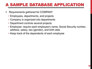
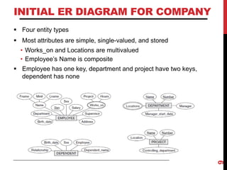
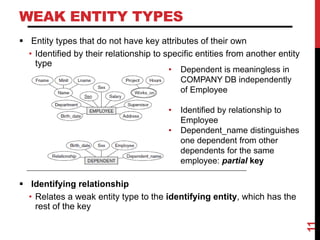
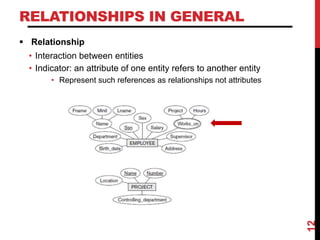
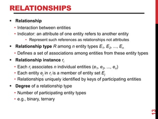
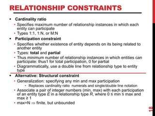
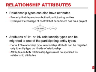
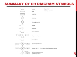
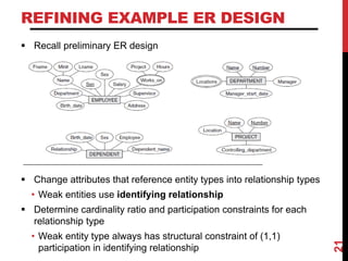
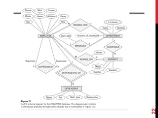
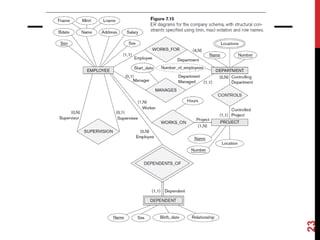
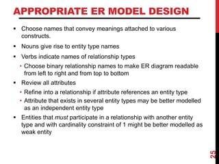
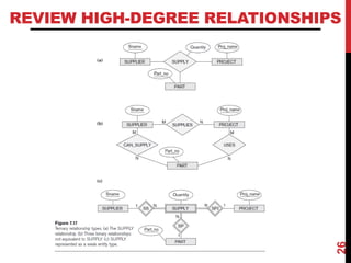
THE ENTITY-
RELATIONSHIP (ER)
MODEL
CHAPTER 7 (6/E)
CHAPTER 3 (5/E)
LECTURE OUTLINE
 Using High-Level, Conceptual Data Models for Database Design
 Entity-Relationship (ER) model
• Popular high-level conceptual data model
 ER diagrams
• Diagrammatic notation associated with the ER model
2
STEPS IN DATABASE DESIGN
 Requirements collection and analysis
• DB designers interview prospective DB users to understand and
document data requirements
• Data requirements
• Functional requirements of the principal applications
 Conceptual or logical DB design
• Description of data requirements
• Detailed descriptions of components and constraints
• Transformed into implementation data model
• Result: DB schema in implementation data model of DBMS
 Physical DB design
• Internal storage structures, file organizations, indexes, access
paths, and physical design parameters for the DB files
 External or view design
3
A SAMPLE DATABASE APPLICATION
 Requirements gathered for COMPANY
• Employees, departments, and projects
• Company is organized into departments
• Department controls several projects
• Employee: require each employee’s name, Social Security number,
address, salary, sex (gender), and birth date
• Keep track of the dependents of each employee
4
ER MODEL OVERVIEW
 ER model describes data in terms of:
• Entities and entity sets
• Objects
• Relationships and relationship sets
• Connections between objects
• Attributes
• Properties that characterize or describe entities or relationships
5
ENTITIES AND ATTRIBUTES EXAMPLE
6
ENTITY SETS
 Entity type or set
• Collection (or set) of similar entities that have the same attributes
 ER model defines entity sets, not individual entities
 But entity sets described in terms of their attributes
7
CATEGORIES OF ATTRIBUTES
 Simple (atomic) vs. composite attributes
 Single-valued vs. multivalued attributes
 Stored vs. derived attributes
 Key or unique attributes
• Attribute values constrained to be distinct for individual entities in
entity set
8
INITIAL ER DIAGRAM FOR COMPANY
 Four entity types
 Most attributes are simple, single-valued, and stored
• Works_on and Locations are multivalued
• Employee’s Name is composite
 Employee has one key, department and project have two keys,
dependent has none
9
WEAK ENTITY TYPES
 Entity types that do not have key attributes of their own
• Identified by their relationship to specific entities from another entity
type
 Identifying relationship
• Relates a weak entity type to the identifying entity, which has the
rest of the key
11
• Dependent is meaningless in
COMPANY DB independently
of Employee
• Identified by relationship to
Employee
• Dependent_name distinguishes
one dependent from other
dependents for the same
employee: partial key
RELATIONSHIPS IN GENERAL
 Relationship
• Interaction between entities
• Indicator: an attribute of one entity refers to another entity
• Represent such references as relationships not attributes
12
RELATIONSHIPS
 Relationship
• Interaction between entities
• Indicator: an attribute of one entity refers to another entity
• Represent such references as relationships not attributes
 Relationship type R among n entity types E1, E2, ..., En
• Defines a set of associations among entities from these entity types
 Relationship instance ri
• Each ri associates n individual entities (e1, e2, ..., en)
• Each entity ej in ri is a member of entity set Ej
• Relationships uniquely identified by keys of participating entities
 Degree of a relationship type
• Number of participating entity types
• e.g., binary, ternary
13
RELATIONSHIPS & RELATIONSHIP SETS
14
DIAGRAMMING RELATIONSHIP TYPE
 Diamond for relationship type
 Connected to each participating entity type
• Could be binary, ternary, or higher degree
 Remember:
• Represents a set of entities of each type,
some of which are related to entities of the
other type(s)
• Some entities might participate in several
relationships
• Some entities might not participate in the
relationship at all
15
RELATIONSHIPS WITH
REPEATED ENTITY SETS
 Some relationships involve multiple entities from the same entity set
• e.g., spouse (two persons), games (two teams)
• e.g., recursive relationships, such as supervises (two employees)
 Role name
• Signifies role that participating entity plays in relationship instance
• Required when entity type participates multiple times in a
relationship
16
USING ROLE NAMES
17
RELATIONSHIP CONSTRAINTS
 Cardinality ratio
• Specifies maximum number of relationship instances in which each
entity can participate
• Types 1:1, 1:N, or M:N
 Participation constraint
• Specifies whether existence of entity depends on its being related to
another entity
• Types: total and partial
• Thus minimum number of relationship instances in which entities can
participate: thus1 for total participation, 0 for partial
• Diagrammatically, use a double line from relationship type to entity
type
 Alternative: Structural constraint
• Generalization: specifying any min and max participation
• Replaces cardinality ratio numerals and single/double line notation
• Associate a pair of integer numbers (min, max) with each participation
of an entity type E in a relationship type R, where 0 ≤ min ≤ max and
max ≥ 1
• max=N  finite, but unbounded
18
RELATIONSHIP ATTRIBUTES
 Relationship types can also have attributes
• Property that depends on both/all participating entities
• Example: Percentage of control that department has on a project
 Attributes of 1:1 or 1:N relationship types can be
migrated to one of the participating entity types
• For a 1:N relationship type, relationship attribute can be migrated
only to entity type on N-side of relationship
• Attributes on M:N relationship types must be specified as
relationship attributes
19
Percent
CONTROLS
SUMMARY OF ER DIAGRAM SYMBOLS
20
⟹ 1 E1 entity can be related to N E2 entities
REFINING EXAMPLE ER DESIGN
 Recall preliminary ER design
 Change attributes that reference entity types into relationship types
• Weak entities use identifying relationship
 Determine cardinality ratio and participation constraints for each
relationship type
• Weak entity type always has structural constraint of (1,1)
participation in identifying relationship
21
22
23
APPROPRIATE ER MODEL DESIGN
 Choose names that convey meanings attached to various
constructs.
 Nouns give rise to entity type names
 Verbs indicate names of relationship types
• Choose binary relationship names to make ER diagram readable
from left to right and from top to bottom
 Review all attributes
• Refine into a relationship if attribute references an entity type
• Attribute that exists in several entity types may be better modelled
as an independent entity type
 Entities that must participate in a relationship with another entity
type and with cardinality constraint of 1 might be better modelled as
weak entity
25
REVIEW HIGH-DEGREE RELATIONSHIPS
26
LECTURE SUMMARY
 Components of the Entity-Relationship Model
• Entity Types, Entity Sets
• Weak Entity Types
• Relationship Types, Relationship Sets, Roles
• Attributes, Attribute Classification, Keys
• Structural Constraints
 ER diagrams represent ER models
 Appropriate ER design
28

Dbms Model.pdf

  • 1.
  • 2.
    LECTURE OUTLINE  UsingHigh-Level, Conceptual Data Models for Database Design  Entity-Relationship (ER) model • Popular high-level conceptual data model  ER diagrams • Diagrammatic notation associated with the ER model 2
  • 3.
    STEPS IN DATABASEDESIGN  Requirements collection and analysis • DB designers interview prospective DB users to understand and document data requirements • Data requirements • Functional requirements of the principal applications  Conceptual or logical DB design • Description of data requirements • Detailed descriptions of components and constraints • Transformed into implementation data model • Result: DB schema in implementation data model of DBMS  Physical DB design • Internal storage structures, file organizations, indexes, access paths, and physical design parameters for the DB files  External or view design 3
  • 4.
    A SAMPLE DATABASEAPPLICATION  Requirements gathered for COMPANY • Employees, departments, and projects • Company is organized into departments • Department controls several projects • Employee: require each employee’s name, Social Security number, address, salary, sex (gender), and birth date • Keep track of the dependents of each employee 4
  • 5.
    ER MODEL OVERVIEW ER model describes data in terms of: • Entities and entity sets • Objects • Relationships and relationship sets • Connections between objects • Attributes • Properties that characterize or describe entities or relationships 5
  • 6.
  • 7.
    ENTITY SETS  Entitytype or set • Collection (or set) of similar entities that have the same attributes  ER model defines entity sets, not individual entities  But entity sets described in terms of their attributes 7
  • 8.
    CATEGORIES OF ATTRIBUTES Simple (atomic) vs. composite attributes  Single-valued vs. multivalued attributes  Stored vs. derived attributes  Key or unique attributes • Attribute values constrained to be distinct for individual entities in entity set 8
  • 9.
    INITIAL ER DIAGRAMFOR COMPANY  Four entity types  Most attributes are simple, single-valued, and stored • Works_on and Locations are multivalued • Employee’s Name is composite  Employee has one key, department and project have two keys, dependent has none 9
  • 10.
    WEAK ENTITY TYPES Entity types that do not have key attributes of their own • Identified by their relationship to specific entities from another entity type  Identifying relationship • Relates a weak entity type to the identifying entity, which has the rest of the key 11 • Dependent is meaningless in COMPANY DB independently of Employee • Identified by relationship to Employee • Dependent_name distinguishes one dependent from other dependents for the same employee: partial key
  • 11.
    RELATIONSHIPS IN GENERAL Relationship • Interaction between entities • Indicator: an attribute of one entity refers to another entity • Represent such references as relationships not attributes 12
  • 12.
    RELATIONSHIPS  Relationship • Interactionbetween entities • Indicator: an attribute of one entity refers to another entity • Represent such references as relationships not attributes  Relationship type R among n entity types E1, E2, ..., En • Defines a set of associations among entities from these entity types  Relationship instance ri • Each ri associates n individual entities (e1, e2, ..., en) • Each entity ej in ri is a member of entity set Ej • Relationships uniquely identified by keys of participating entities  Degree of a relationship type • Number of participating entity types • e.g., binary, ternary 13
  • 13.
  • 14.
    DIAGRAMMING RELATIONSHIP TYPE Diamond for relationship type  Connected to each participating entity type • Could be binary, ternary, or higher degree  Remember: • Represents a set of entities of each type, some of which are related to entities of the other type(s) • Some entities might participate in several relationships • Some entities might not participate in the relationship at all 15
  • 15.
    RELATIONSHIPS WITH REPEATED ENTITYSETS  Some relationships involve multiple entities from the same entity set • e.g., spouse (two persons), games (two teams) • e.g., recursive relationships, such as supervises (two employees)  Role name • Signifies role that participating entity plays in relationship instance • Required when entity type participates multiple times in a relationship 16
  • 16.
  • 17.
    RELATIONSHIP CONSTRAINTS  Cardinalityratio • Specifies maximum number of relationship instances in which each entity can participate • Types 1:1, 1:N, or M:N  Participation constraint • Specifies whether existence of entity depends on its being related to another entity • Types: total and partial • Thus minimum number of relationship instances in which entities can participate: thus1 for total participation, 0 for partial • Diagrammatically, use a double line from relationship type to entity type  Alternative: Structural constraint • Generalization: specifying any min and max participation • Replaces cardinality ratio numerals and single/double line notation • Associate a pair of integer numbers (min, max) with each participation of an entity type E in a relationship type R, where 0 ≤ min ≤ max and max ≥ 1 • max=N  finite, but unbounded 18
  • 18.
    RELATIONSHIP ATTRIBUTES  Relationshiptypes can also have attributes • Property that depends on both/all participating entities • Example: Percentage of control that department has on a project  Attributes of 1:1 or 1:N relationship types can be migrated to one of the participating entity types • For a 1:N relationship type, relationship attribute can be migrated only to entity type on N-side of relationship • Attributes on M:N relationship types must be specified as relationship attributes 19 Percent CONTROLS
  • 19.
    SUMMARY OF ERDIAGRAM SYMBOLS 20 ⟹ 1 E1 entity can be related to N E2 entities
  • 20.
    REFINING EXAMPLE ERDESIGN  Recall preliminary ER design  Change attributes that reference entity types into relationship types • Weak entities use identifying relationship  Determine cardinality ratio and participation constraints for each relationship type • Weak entity type always has structural constraint of (1,1) participation in identifying relationship 21
  • 21.
  • 22.
  • 23.
    APPROPRIATE ER MODELDESIGN  Choose names that convey meanings attached to various constructs.  Nouns give rise to entity type names  Verbs indicate names of relationship types • Choose binary relationship names to make ER diagram readable from left to right and from top to bottom  Review all attributes • Refine into a relationship if attribute references an entity type • Attribute that exists in several entity types may be better modelled as an independent entity type  Entities that must participate in a relationship with another entity type and with cardinality constraint of 1 might be better modelled as weak entity 25
  • 24.
  • 25.
    LECTURE SUMMARY  Componentsof the Entity-Relationship Model • Entity Types, Entity Sets • Weak Entity Types • Relationship Types, Relationship Sets, Roles • Attributes, Attribute Classification, Keys • Structural Constraints  ER diagrams represent ER models  Appropriate ER design 28