Download to read offline
![IOSR Journal of Mechanical and Civil Engineering (IOSR-JMCE)
e-ISSN: 2278-1684,p-ISSN: 2320-334X, Volume 13, Issue 4 Ver. II (Jul. - Aug. 2016), PP 25-32
www.iosrjournals.org
DOI: 10.9790/1684-1304022532 www.iosrjournals.org 25 | Page
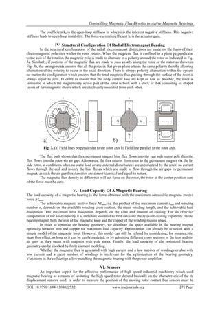
Controlling Magnetic Flux Density in Active Magnetic Bearings
Prince Owusu-Ansah1
, Alex Frimpong Justice2
, Timothy Alhassan3
,
Saviour Kwame Woangbah4
.
1
School of Mechanical and Electronic Engineering, Wuhan University of Technology
1
Mechanical Engineering Department, Kumasi Polytechnic P. O. Box 854, Kumasi Ghana
2,3,4
Mechanical Engineering Department, Kumasi Polytechnic P. O. Box 854, Kumasi Ghana
Abstract: This paper discusses the control of magnetic flux density in active magnetic bearings. The rotor is
laminated in which the magnetically active part of the rotor is built with stacks of disk consisting of shaped
layers of ferromagnetic sheets which are electrically insulated from each other.
The use of different applications of control measures depending on its application, linearity, measuring range,
resolution, sensitivity as well as its frequency range causes the output signal of its sensors to change according
to its physical effect as a function of the measured quantity during the process of measurements.
Finally, different types of displacement sensor, it’s measuring principles and the various types of application
used in the measurement of magnetic flux density has been studied and presented.
Keywords: Active magnetic bearing, Current Measurement, Magnetic flux density, Rotor, Sensor,
I. Introduction
Magnetic bearings are bearings which supports loads using magnetic levitation [1], they support
moving machinery without making physical contact with each other, for example, they can levitate a rotating
shaft and permit relative motion without friction or wear, they are essentially used in industrial applications such
as electric power generation, petroleum refining, machine tool operation, natural gas pipelines, zippe-type etc.
Active magnetic bearings (AMB) are clearly favored over passive bearings [2], because they are
actively controlled by means of electromagnet and results in high power loss due to the presence of a biased
current, but the inclusion of suitable feedback control loops and other elements such as sensors and power
amplifier makes its more preferable than passive bearing due to its lack of active control damping capabilities
[3, 4] Passive magnetic bearing consists of permanent magnetic placed in a position that can levitate an object in
this case, the rotor making it contact free using the principles of magnetic effect [5, 6].
The first group of magnetic bearing classifications are referred to as reluctance force bearings, whiles
the second group is made up by the Lorentz force bearings. Whereas the latter type of bearings has lately gained
an increasing importance mainly in the field of the self-bearing motors, it is still the case that the bulk of
industrial magnetic bearing applications employ reluctance force bearings. In such bearing designs magnetic
flux provides a bias flux which flows radially in an open iron-core ring and then moves directly into the four
poles of the stator through the airgaps and then moves through the stator alongside the axial direction before it
finally returns to the rotor via the other airgaps.
The electromagnet flux generated from the upper and lower magnets coils passes down through the
rotor along the radial direction on one side, and then passes up through the other side of the rotor finally. Thus,
if the total flux increases in the lower side, it then results in the reduction of magnet flux at the upper portion of
the rotor, the resultant difference of the magnetic flux as a result of this process produces a control force in the
magnetic bearing for the suspension and levitation action for the rotor to be suspended and control very
effectively throughout it rotational operation.
II. Magnetic Bearing As A Controlled Suspension
Active magnetic bearing consists of a copper coil, in some cases high temperature superconductors
which provides high magnetic flux ensuring contact free movement in these designs [7].
AMB has good performance and with a microprocessor control based it compensates the instability that
will occur in the system [8]. In active magnetic it is possible to design and adapt different functionalities in
relation to different points of view of which the most important are of the following.
Position of the active circuit: The position of the active circuit in the design is done keeping in mind the
main function of AMB are to levitate, sustain and align the rotating mass of the flywheel rotor. The active
bearing structure has a coil placed inside it which constitutes the active circuit of the AMB, that suppliers the
coil current to the system.](https://image.slidesharecdn.com/d1304022532-160729083916/85/D1304022532-1-320.jpg)
![Controlling Magnetic Flux Density in Active Magnetic Bearings
DOI: 10.9790/1684-1304022532 www.iosrjournals.org 26 | Page
III. Relation Between Current And Force In An Active Magnetic Bearing
It is assumed that the magnetic flux ɸ [T.m2
], in the stator cross-section Afe [m2
] is constant along the
whole loop. Afe = Aa (Aa is the cross-section of the air-gap), Thus,
ɸ = BfeAfe =BaAa (1)
Bfe = Ba = B (2)
Fig. 1. Magnetic force of an AMB.
The magnetic path is decomposed two parts, the field in the air, and in the soft magnetic material.
B = µµoH (3)
Ni = Hfe lfe + 2Has (4)
Where s [m] is the air gap between stator and rotor. The average magnetic path length in the lamination is lfe
[m].
From Eq. (3) and Eq. (4) and solving for B yields Equation. (5) as the flux density.
B = µoNi/((lfe/µr)+2s) (5)
Since the iron relative permeability µr » 1, the magnetization of the iron can often be neglected, and the relation
can be written as
B ≈ µoNi/2s (6)
The AMB force is obtained by considering the energy stored in the air gap and is given by equation. (7)
F = Ba
2
Aa/µo (7)
The angle between the force direction and the center of the cross-section A is determined by . In a four poles
radial AMBs, which means eight actuator teeth, α is 22.5°. Equation (6) and equation (7) results in the force for
one actuator:
F = ¼ µoN2
Aa (i2
/s2
) cosα = k(i2
/s2
)cosα (8)
F = ¼ µoN2
Aa (9)
In order to produce a magnetic force along two opposite directions, the actuators are arranged in pairs
as indicated in fig. 1 this enables a full control of the rotor along one axis. For the pair of magnets, the force Fx
[N] represents the force difference between the positive and the negative directions, the actuator currents are
defined as the sum of a bias current io [A] and a control current ix [A] for the positive actuator, and the difference
(io -ix) for the negative actuator. The air gaps are defined by the deviation x [m] and the nominal air gap so [m],
thus the terms (so-x) and (so + x) are inserted.
Fx = F+ - F- = k((io + ix)2
/(so-x)2
)- (io -ix)2
/(so + x)2
)cosα (10)
k = ¼ µoN2
Aa (11)
By considering that (x « so) and (ix « io), equation (10) can be linearized using Taylor’s series. It yields
the typical AMB relation in Equation. (13).
Fx = 4k(io/so
2
)(cosα)ix +4k(io/so
2
)(cosα)x = kiix + kxx (12)
Ks = ki(io/so) (13)
Fig. 2. Differential bearing mode of the bearing magnets.](https://image.slidesharecdn.com/d1304022532-160729083916/85/D1304022532-2-320.jpg)
![Controlling Magnetic Flux Density in Active Magnetic Bearings
DOI: 10.9790/1684-1304022532 www.iosrjournals.org 29 | Page
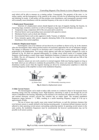
4. Eddy Current Radial Displacement Sensor ON A PCB Transverse Flux Sensor
To minimize space requirement and for the purpose to save production cost of the sensor it is usually
desirable to place the eddy current sensor coils directly on a printed circuit board (PCB) which is placed around
the rotor, such a design is called Transverse Flux Sensor [9].
The magnetic field of the coil in an eddy current displacement sensor is normally directed towards the
rotor in such a way that the axis of the rotor of the radial sensor coil is perpendicular to its axis of rotation in
Fig. 6.
This arrangement is made to provide a suitably sensitivity to a target displacement only is specific
direction which is perpendicular to the coil surface, where sensitivity to displacements in any lateral direction is
poor. This behavior is due to the fact that magnetic field strength is very high at the coil’s center and that its
maximum field strength is very high at the coil center and that the maximum field gradient component which is
perpendicular to its surface.
(a) Rotor concentric within the sensor (b) With rotor displacement
Fig. 6. Transverse Flux Sensor
The strength of the electro-magnetic field of the excitation is dependent on the position of the rotor
within the excitation coil measuring this field strength with the detection coil will give the high lateral
sensitivity in the x and y directions.
5. Capacitive Displacement
The capacity of a plate capacitor varies with its clearance. In capacitive measuring method, the sensor
and the opposing object which is to be measured forms one electrode of the plate. Fig. 5b. In the measuring
system, an alternating current which constant of a constant frequency runs through the sensor. The voltage of the
sensor is proportional to the clearance between the sensor electrode and the object which is to be measured, and
it is demodulated and amplifier by a special circuit. The bandth width of the output signal ranges between 5 kHz
and 100 kHz.
The electrostatic charging of the countless rotor will cause interferences. The sensors are sensitive to
dirt which could modify the dielectric constant in the air gap.
6. Magnetic Displacement Sensors
When current i in a magnetic displacement sensor is kept constant in a magnetic loop within an air gap,
the flux density B can be used to measure the size of the air gap. In Fig. 7, a well linearized displacement signal
results from the difference between the measured flux density U Bp – U Bn. Flux density B is measured with a
Hall sensor or with a field plate. Magnetic displacement sensors are very sensitive to interference by external
fields.
Fig. 7. Combined displacement -velocity sensor
Velocity Measurement
When the current i is kept constant in a magnetic circuit, the flux Ф varies with the air gap. The voltage
U is proportional to the derivative dФ/dt and the velocity dx/dt When the combined displacement- velocity
sensor as shown in Fig. 7, is used, the difference between the voltages Up – Un yields a nearly velocity signal.
This type of sensor is very appropriate for measuring displacement and velocity; further permanent magnet can
also be used in this situation instead of electric excitement.](https://image.slidesharecdn.com/d1304022532-160729083916/85/D1304022532-5-320.jpg)
![Controlling Magnetic Flux Density in Active Magnetic Bearings
DOI: 10.9790/1684-1304022532 www.iosrjournals.org 30 | Page
Flux And Current Measurement
Hall Effect
In situations where current travels along a piece of thin, a band- shaped conductor, and when this
conductor lies in a magnetic field which is perpendicular to the band plane, forces which are made to act
perpendicular to their band on the electrons moves at a drifting speed v along the conductor as indicated in Fig
8. This usually leads to accumulation of positive and negative charges on both longitudinal sided within the
band, and consequently to an electric voltage Ub. This Hall voltage is proportional to the flux density B and the
current i [10].
Ub =kh Bi (14)
The proportionality factor kh depends on the type of geometry of the conductor and its material, in
measuring the flux density, the Hall sensor is driven by a constant – current source. Hall sensors can be
optimized regarding the size of the proportionality factor kh and the temperature drift of the zero point.
Fig. 8. Hall Effect
Coil And Integrator
The law of induction states that the voltage across a coil with n turns is given as
U = nd/dt (15)
When a measurement coil is mounted on a magnet the resulting voltage is fed to an electronic
integrator, the integrator output signal will be proportional to the magnetic flux through the measurement coil as
shown in Fig. 9 This method, however, has the disadvantage that only the alternating components of the flux can
therefore be measured.
Fig. 9. Flux measurement with coil and integrator
VII. Current Measurement With A Hall Sensor
One of the most common method of measuring current with isolation uses a Hall sensor in a magnetic
loop that is excited by one or several turns of the current i which is to be measured. The flux density which is
measured by the Hall sensor is equilibrated with a controller, a power amplifier and an auxiliary coil as
indicated in Fig. 10. The zero balance situation is reached when the flux from the current presence in the
auxiliary winding with the number of n turns is opposite to the flux that is generated by the current i to be
measured. The input signal Ui of the power amplifier is a direct measure of the current i
Fig. 10. Current measurement with a Hall sensor](https://image.slidesharecdn.com/d1304022532-160729083916/85/D1304022532-6-320.jpg)
![Controlling Magnetic Flux Density in Active Magnetic Bearings
DOI: 10.9790/1684-1304022532 www.iosrjournals.org 31 | Page
VIII. Rotor Control Positioning
Having a magnetic bearing which consist of an active circuit, it is very possible to control the position
of the rotating rotor mass as shown in Fig. 11.
Fig. 11. Position of a rotating rotor
The rotor control position is typically based on a position sensor which has a very important function
since in the setup flywheel energy storage system the system requires adequate control system not only
controlling the AMB circuits but also the electrical machine such as the industrial flywheel machinery.
IX. Conclusion
Magnetic flux density in active magnetic bearings have been discussed and presented in this paper. The
flux path shows that bias flux flows into the rear side of the stator pole more than it flows into the upper portion
of the rotor as presented in Fig .3.
In capacitive measuring method, the sensor and the opposing object which is to be measured forms one
electrode of the plate, as such during the measuring process an alternating current which consists of a constant
frequency is made to run through the sensor in which the sensor voltage is proportional to the clearance between
the sensor electrode and the object which is to be measured which is demodulated and amplifier by a special
circuit.
It could be noted that all of these areas are active foci of current AMB research. In sensing, there is a
continual interest in better integration of sensing into the overall AMB structure, in reducing cost, and in
reducing noise coupling between the magnet coils and the sensing head. In high precision application like
grinding, milling or high speed rotating machinery such as flywheel rotors, premium is always placed on sensor
performance.
An important part in the performance of the active magnetic bearing designs depends on the
characteristics of the type of displacement sensor that are used. In order to measure the position of a moving
rotor, contact-free sensor must be used, and moreover must be able to measure on the rotor rotating surface. In
controlling magnetic flux in AMBs, the geometry of the rotor, that is its surface quality as well as the
homogeneity of the material of the sensor have a direct influence on the outcome of the measuring results of the
system being measured.
It addition a bad surface will thus produce noise and geometry errors may cause disturbances from the
rotational frequency.
Acknowledgement
Authors are grateful to the Natural Science Foundation of China (NO.51275372), Wuhan High-Tech
Development Project Foundation (NO.201110921299) and The Fundamental Research Funds for the Central
Universities (Wuhan University of Technology No.2012-IV-036) for supporting this research work.
References
[1]. A.V. Filator, and E.H. Maslen, Passive Magnetic Bearing for Flywheel Energy System, 7th International Conference on Vibration
and control systems, 56(8), 2000, 143-148.
[2]. R. Larsonneur, G. Schweitzer, and E. Maslen, Control of the Rigid Rotor in AMBs”. 10th
Symp. on Magnetic Bearings – Theory,
Design, and Application to Rotating Machinery 15(16), 2009, 170–228.
[3]. G. Schweitzer. Active Magnetic Bearings-Chances and Limitation, Sixth International conference on rotor Dynamics and Control
Applications 15(17), 2002, 1-14.
[4]. G. Schweitzer, H. Bleuler. A Traxle. Basic Design and Theory of Magnetic Bearings, International conference on Active Magnetic
Bearings Basics Properties and Applications, 12(6),1994,1234-1243.
[5]. P. Samantha, H. Hirani, Magnetic Bearing Configuration, Theoretical and Experimental Studies, In proceedings of the Tenth
International Symposium on Magnetic Bearings, 18(16), 2008, 150-157.](https://image.slidesharecdn.com/d1304022532-160729083916/85/D1304022532-7-320.jpg)
![Controlling Magnetic Flux Density in Active Magnetic Bearings
DOI: 10.9790/1684-1304022532 www.iosrjournals.org 32 | Page
[6]. R. Larsonneur, G. Schweitzer, and E. Maslen, 6th
International conference on Magnetic Bearings – Theory, Design, and Application
to Rotating Machinery. 7(8), 2009, 456-462.
[7]. M. Spirig, J. Schmied, U. Kanne. The 3rd
Symp. on Practical Examples of Magnetic Bearing Control Design using modern tools.
ASME Journal of Engineering for Gas Turbine and Power Controls, 17(18), 2002, 1025-1031.
[8]. R. Larsonneur, R. Stewart, and A. Traxler, A. Active Magnetic Bearing Control of Magnetic Bearing Systems with Imbalance. In
Proceedings of the 5th International Symposium on Magnetic Bearings, 8 (9), 2008, 344-354.
[9]. K. Zhang, H. Zhao. Research on Flywheel Suspended by AMB, s with Significant Gyroscopic Effect, Journal of Chinese
Mechanical Engineering, 17(1), 2004, 34-39.
[10]. E. Knopf, R. Nordmann. Active Magnetic Bearings for the Identification of Dynamic Characteristics of Fluid Bearings, In 6th
International Symposium on Magnetic Bearings, 14(10), 1998, 34-36.](https://image.slidesharecdn.com/d1304022532-160729083916/85/D1304022532-8-320.jpg)

This document discusses controlling magnetic flux density in active magnetic bearings. It describes how active magnetic bearings use electromagnets and feedback control loops to levitate and stabilize a rotating shaft without physical contact. Various sensor types are discussed for measuring the displacement of the levitated rotor, including inductive, eddy current, and capacitive sensors. The relationship between actuator current and magnetic force is explained, showing how current controls the flux density and resulting forces in the bearing.


![[IJET-V2I1P8] Authors:Mr. Mayur k Nemade , Porf. S.I.Kolhe](https://cdn.slidesharecdn.com/ss_thumbnails/ijet-v2i1p8-160427182554-thumbnail.jpg?width=640&height=640&fit=bounds)


