Download to read offline
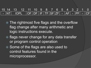
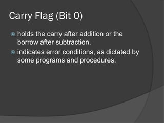
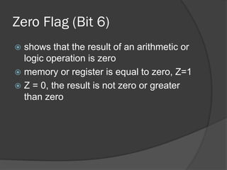
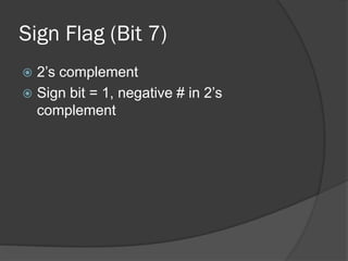

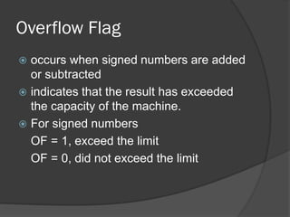

The document discusses the flags in a microprocessor that indicate the status of arithmetic and logic operations. It explains that the carry flag, parity flag, auxiliary flag, zero flag, sign flag, and overflow flag can change after arithmetic and logic instructions but not data transfer or program control operations. It then provides details on what each flag indicates, such as the carry flag showing carries/borrows, the zero flag indicating a result of zero, and the overflow flag exposing when a signed number operation exceeds capacity.