SlideShare a Scribd company logo
1 of 139
Download to read offline
8 Jump and call
This chapter considers the jump instruction which enables part of a
program to be jumped over and the way in which subroutines in ladder
programmes can be called up. Subroutines enable commonly occurring
operations in a program to be repeatedly called up and used over again.
8.1 Jump A function often provided with PLCs is the conditional jump. We can
describe this as:
IF (some condition occurs) THEN
perform some instructions
ELSE
perform some other instructions.
Such a facility enables programs to be designed such that if certain
conditions are met then certain events occur, if they are not met then other
events occur. Thus, for example, we might need to design a system so that
if the temperature is above 60o
C a fan is switched on, and if below that
temperature no action occurs.
Thus, if the appropriate conditions are met, this function enables part of
a ladder program to be jumped over. Figure 8.1 illustrates this in a general
manner. When there is an input to In 1, its contacts close and there is an
output to the jump relay. This then results in the program jumping to the
rung in which the jump end occurs, so missing out intermediate program
rungs. Thus, in this case, when there is an input to Input 1, the program
jumps to rung 4 and then proceeds with rungs 5, 6, etc. When there is no
input to Input 1, the jump relay is not energised and the program then
proceeds to rungs 2, 3, etc.
Figure 8.2(a) shows the above ladder program in the form used by
Mitsubishi. The jump instruction is denoted by CJP (conditional jump) and
the place to which the jump occurs is denoted by EJP (end of jump). The
condition that the jump will occur is then that there is an input to X400.
When that happens the rungs involving inputs X401 and X403 are ignored
and the program jumps to continue with the rungs following the end jump
instruction with the same number as the start jump instruction, i.e. in this
case EJP 700.
With the Allen-Bradley PLC-5 format the jump takes place from the
jump instruction (JMP) to the label instruction (LBL). The JMP instruction
is given a three-digit number from 000 to 255 and the LBL instruction the
same number. Figure 8.2(b) shows a ladder program in this format.
Input 1 Jump
Jump end
Rung 1
Rung 2
Rung 3
Rung 4
etc.
Figure 8.1 Jump
X400
X401
X402
Y430
Y431
CJP 700
EJP 700
Input 1
Input 2
Input 3
Output 1
Output 2
Jump between
these rungs
of the program
if input 1 occurs
JMP
LBL
I:012/10
I:012/11
I:012/12
010
010
O:012/10
O:012/11
O:012/12
Jump if input
Input Jump
Label Output
I:012/10 occurs
(a) (b)
Figure 8.2 Jump: (a) Mitsubishi program, (b) Allen-Bradley program
With Siemens’ programs, conditional jumps are represented as shown
in Figure 8.3, there being a jump instruction JMP which is executed if the
input is a 1 and another jump instruction JMPN which is executed if the
input is 0. The end of both instructions is the label DEST.
JMP Jump if
input 1
JMPN Jump if
input 0
DEST End of jump
Figure 8.3 Siemens’ jump instructions
8.1.1 Jumps within jumps
Jumps within jumps are possible. For example, we might have the
situation shown in Figure 8.4. If the condition for the jump instruction 1 is
realised then the program jumps to rung 8. If the condition is not met then
the program continues to rung 3. If the condition for the jump instruction
2 is realised then the program jumps to rung 6. If the condition is not met
then the program continues through the rungs.
Thus if we have an input to In 1, the rung sequence is rung 1, 8, etc. If
we have no input to In 1 but an input to In 3, then the rung sequence is 1,
2, 6, 7, 8, etc. If we have no input to In 1 and no input to In 3, the rung
sequence is 1, 2, 3, 4, 5, 6, 7, 8, etc. The jump instruction enables
different groups of program rungs to be selected, depending on the
conditions occurring.
Jump and call 155
Rung 1
Rung 2
Rung 3
Rung 4
Rung 5
Rung 6
Rung 7
Rung 8
Jump 1
Jump 2
In 1
In 3
Jump 2 end
Jump 1 end
If In 1
If In 3
Figure 8.4 Jumps within jumps
8.2 Subroutines Subroutines are small programs to perform specific tasks which can be
called for use in larger programs. Thus with a Mitsubishi program we
might have the situation shown in Figure 8.5(a). When input 1 occurs, the
subroutine P is called. This is then executed, the instruction SRET
indicating its end and the point at which the program returns to the main
program. To clearly indicate where the main program ends the FEND
instruction is used.
With Allen-Bradley, subroutines are called by using a jump-to-
subroutine JSR instruction, the start of the subroutine being indicated by
SBR and its end and point of return to the main program by RET (Figure
8.5(b)).
With Siemens a similar format can be adopted, using CALL to call up a
subroutine block and RET to indicate the return instruction to the main
program. However, a function box approach (Figure 8.6) can be used and
is particularly useful where there is a library of subroutine functions to be
called. If the EN (enable) block input is connected directly to the left
power rail then the call is without conditions and always executed. If there
is a logic operation preceding EN then the block call is only executed if the
logic condition is fulfilled, in Figure 8.6 this is closure of contacts of Input
1. Several blocks can be connected in series by connecting the ENO,
enable output, of one to the EN input of the next.
156 Programmable Logic Controllers
Input 1
CALL P
Main program and
Call to subroutine
etc.
FEND End of main program
; Subroutine
etc.
SRET
Subroutine
END End of entire program
End of subroutine and
return to main program
JSR
etc
Jump to subroutine
Main program
SBR
RET
Subroutine
Return to main
program
(a)
return point after
subroutin
(b)
conditional on Input 1
Input 1
conditional on
Input 1
Figure 8.5 (a) Subroutine call with Mitsubishi PLC, (b) jump to subroutine call with Allen-Bradley PLC
Subroutine block FCx
Return to main program
FCx
EN
IN1
IN2
OUT
ENO enabled when input to EN
Main program prior to call
Processing of the block parameters
Output when IN1 AND IN2
Input 1
Figure 8.6 Call to subroutine block with Siemens PLC
Problems Questions 1 to 4 have four answer options: A, B, C or D. Choose the
correct answer from the answer options.
Problems 1 and 2 refer to Figure 8.7 which shows a ladder diagram
with inputs In 1, In 2, In 3 and In 4, outputs Out 1, Out 2, Out 3 and
Out 4 and a Jump instruction.
1 For the ladder diagram shown in Figure 8.8, for output Out 1 to
occur:
Jump and call 157
A Only input In 1 must occur
B Both inputs In 1 and In 2 must occur
C Input In 1 must not occur and input 2 must occur
D Both inputs In 1 and In 2 must not occur
2 Decide whether each of these statements is True (T) or False (F).
For the ladder diagram shown in Figure 8.8, following input In 1:
(i) Output 1 occurs.
(ii) Output 3 occurs.
A (i) T (ii) T
B (i) T (ii) F
C (i) F (ii) T
D (i) F (ii) F
Problems 3 and 4 refer to Figure 8.8 which shows a ladder diagram
with inputs In 1, In 2, and In 3, outputs Out 1, Out 2, Out 3 and a
jump-to-subroutine instruction.
3 Decide whether each of these statements is True (T) or False (F).
For the ladder diagram shown in Figure 8.8:
(i) After input In 1 occurs output Out 2 occurs.
(ii) After output 3 occurs the program waits for input In 2 before
proceeding
A (i) T (ii) T
B (i) T (ii) F
C (i) F (ii) T
D (i) F (ii) F
4 Decide whether each of these statements is True (T) or False (F).
For the ladder diagram shown in Figure 8.8:
(i) When input In 2 occurs, outputs 1 and 2 occur.
(ii) When input In 3 occurs, output 3 occurs.
A (i) T (ii) T
B (i) T (ii) F
C (i) F (ii) T
D (i) F (ii) F
158 Programmable Logic Controllers
JMP
LBL
In 1 Jump 1
Label 1 Out 3
In 2
In 3
Out 1
Out 2
In 4 Out 4
Figure 8.7 Problems 1 and 2
JSR
SBR
RET
In 1
In 2
In 3
Out 1
Out 2
Out 3
Figure 8.8 Problems 3 and 4
9 Timers
In many control tasks there is a need to control time. For example, a
motor or a pump might need to be controlled to operate for a particular
interval of time, or perhaps be switched on after some time interval. PLCs
thus have timers as built-in devices. Timers count fractions of seconds or
seconds using the internal CPU clock. This chapter shows how such
timers can be programmed to carry out control tasks.
9.1 Types of timers PLC manufacturers differ on how timers should be programmed and
hence how they can be considered. A common approach is to consider
timers to behave like relays with coils which when energised result in the
closure or opening of contacts after some preset time. The timer is thus
treated as an output for a rung with control being exercised over pairs of
contacts elsewhere (Figure 9.1(a)). This is the predominant approach used
in this book. Some treat a timer as a delay block which when inserted in a
rung delays signals in that rung reaching the output (Figure 9.1(b)).
There are a number of different forms of timers that can be found with
PLCs. With small PLCs there is likely to be just one form, the on-delay
timers. These are timers which come on after a particular time delay
(Figure 9.2(a)). Off-delay timers are on for a fixed period of time before
turning off (Figure 9.2(b)). Another type of timer that occurs is the pulse
timer. This timer switches on or off for a fixed period of time (Figure
9.2(c)). Figure 9.3 shows the IEC 1131-3 standard symbols for timers.
TON is used to denote on-delay, TOF off-delay. TP pulse timers.
On-delay is also represented by T 0 and off-delay by 0 T.
Input
Timer
(a) On-delay timer
Input
Timer
(a) Off-delay timer
Input
Timer
(c) Pulse timer
output output output
Figure 9.2 Timers: (a) on-delay, (b) off-delay, (c) pulse
TON
BOOL
TIME
BOOL
TIME
IN
PT
Q
ET
On-delay timer
TOF
BOOL
TIME
BOOL
TIME
IN
PT
Q
ET
Off-delay timer
TP
BOOL
TIME
BOOL
TIME
IN
PT
Q
ET
Pulse timer
Figure 9.3 IEC 1131-1 standards. BOOL indicates a Boolean input/output, i.e. on/off. IN is the input. Q is the
output. ET is the elapsed time output. PT is the input used to specify the time.
(a)
Timer coil
Timer contacts
Time delay
before activated
Timer
Time delay before input
signal reaches output
(b)
Figure 9.1 Treatment of timers
The time duration for which a timer has been set is termed the preset
and is set in multiples of the time base used. Some time bases are typically
10 ms, 100 ms, 1 s, 10 s and 100 s. Thus a preset value of 5 with a time
base of 100 ms is a time of 500 ms. For convenience, where timers are
involved in this text, a time base of 1 s has been used.
9.2 Programming timers All PLCs generally have delay-on timers, small PLCs possibly having
only this type of timer. Figure 9.4(a) shows a ladder rung diagram
involving a delay-on timer. Figure 9.4(a) is typical of Mitsubishi. The
timer is like a relay with a coil which is energised when the input In 1
occurs (rung 1). It then closes, after some preset time delay, its contacts
on rung 2. Thus the output occurs some preset time after the input In 1
occurs. Figure 9.4(b) shows the timer to be a delay item in a rung, rather
than as a relay, the example being for Siemens. When the signal at the
timer’s start input changes from 0 to 1, the timer starts and runs for the
programmed duration, giving its output then to the output coil. The time
value (TV) output can be used to ascertain the amount of time remaining
at any instant. A signal input of 1 at the reset input resets the timer
whether it is running or not. Techniques for the entry of preset time values
vary. Often it requires the entry of a constant K command followed by the
time interval in multiples of the time base used. Figure 9.4(c), (d) and (e)
shows ladder diagrams Telemecanique, Toshiba and Allen-Bradley.
X400 T450 K5
T450 Y430
LD
OUT T450
X400
K 5
LD T450
OUT Y430
(a) (b)
T0
I0.0 Q2.0
KT5.2
A
LKT
SR
A
=
I0.0
5.2
T0
T0
Q2.0
TON
S Q
TV
R
BI
BCD
Input In 1 Timer
Timer Output
Input In 1
S is Boolean start input.
TV is duration of time
specification.
R is Boolean reset.
BI is current time value
in binary word.
BCD is current time
value in BCD word
Q is Boolean output,
indicating state of timer.
I0,0 T0
1 s = TB
P = 10
O0,0
00010 TON T001
X001 Y020
(c)
(d)
TON
I:012/01
TIMER ON
TIMER T4:0
TIME BASE 1:0
PRESET 5
(e)
DN
EN
Input
EN
DN
Time
Time
Time
T4.0
Timer
Input
O:012/10
Output
The enbable bit EN is set to 1
when there is a logic path to
the time. The done bit DN
indicates the status of the
timer and is set to 1 when the
accumulated value equals
the preset value.
Figure 9.4 Timers: (a) Mitsubishi, (b) Siemens, (c) Telemecanique, (d) Toshiba, (e) Allen-Bradley
160 Programmable Logic Controllers
9.2.1 Sequencing
As an illustration of the use of a timer, consider the ladder diagram shown
in Figure 9.5(a). When the input In 1 is on, the output Out 1 is switched
on. The contacts associated with this output then start the timer. The
contacts of the timer will close after the preset time delay, in this case 5.5
s. When this happens, output Out 2 is switched on. Thus, following the
input In 1, Out 1 is switched on and followed 5.5 s later by Out 2. This
illustrates how timed sequence of outputs can be achieved. Figure 9.5(b)
shows the same operation where the format used by the PLC manufacturer
is for the timer to institute a signal delay.
In 1 Out 1
Out 1 Timer
Timer Out 2
Preset
to 5.5
In 1 Out 1
Out 1
TON
Out 2
Timer
Preset to 5.5 s
IN Q
(a) (b)
Figure 9.5 Sequenced outputs
Figure 9.6 shows two versions of how timers can be used to start three
outputs, e.g. three motors, in sequence following a single start button
being pressed. In (a) the timers are programmed as coils, whereas in (b)
they are programmed as delays. When the start push button is pressed
there is an output from internal relay IR1. This latches the start input. It
also starts both the timers, T1 and T2, and motor 1. When the preset time
for timer 1 has elapsed then its contacts close and motor 2 starts. When
the preset time for timer 2 has elapsed then its contacts close and motor 3
starts. The three motors are all stopped by pressing the stop push button.
Since this is seen as a complete program, the end instruction has been
used.
9.2.2 Cascaded timers
Timers can be linked together, the term cascaded is used, to give longer
delay times than are possible with just one timer. Figure 9.7(a) shows the
ladder diagram for such an arrangement. Thus we might have timer 1 with
a delay time of 999 s. This timer is started when there is an input to In 1.
When the 999 s time is up, the contacts for timer 1 close. This then starts
timer 2. This has a delay of 100 s. When this time is up, the timer 2
contacts close and there is an output from Out 1. Thus the output occurs
1099 s after the input to In 1. Figure 9.7(b) shows the Mitsubishi version
of this ladder diagram and the program instructions for that ladder.
Timers 161
END
TON
TON
Motor 1
Motor 2
Motor 3
T1
T2
IR2
IR3
Start Stop IR1
IR1
IR1
IR1
IR1
IR2
IR3
END
Motor 1
Motor 2
Motor 3
Start Stop IR1
IR1
IR1
IR1
IR1
T1
T2
T1
T2
(a) (b)
Start
T1
T2
Motor 1
Motor 2
Motor 3
Stop
Timing diagram
IN Q
IN Q
Figure 9.6 Motor sequence
In 1 Timer 1
Timer 2
Timer 2 Out 1
Preset
999
Preset
100
T450 K999
Timer 1
X400
T450 T451 K100
T451 Y430
LD
OUT
K
LD
OUT
K
LD
OUT
X400
T450
999
T450
T451
100
T451
Y430
(a) (b)
Figure 9.7 Cascaded timers
9.2.3 On off cycle timer
Figure 9.8 shows how on-delay timers can be used to produce an on off
cycle timer. The timer is designed to switch on an output for 5 s, then off
for 5 s, then on for 5 s, then off for 5 s, and so on. When there is an input
to In 1 and its contacts close, timer 1 starts. Timer 1 is set for a delay of 5
s. After 5 s, it switches on timer 2 and the output Out 1. Timer 2 has a
delay of 5 s. After 5 s, the contacts for timer 2, which are normally closed,
162 Programmable Logic Controllers
open. This results in timer 1, in the first rung, being switched off. This
then causes its contacts in the second rung to open and switch off timer 2.
This results in the timer 2 contacts resuming their normally closed state
and so the input to In 1 causes the cycle to start all over again.
In 1 T2 T1 K5
T1
T1
T2 K5
Out 1
In1
T1
T2
Out 1
5 s
5 s
5 s
Time
Time
Time
Time
Figure 9.8 On off cycle timer
Figure 9.9 shows how the above ladder program would appear in the
format used with a timer considered as a delay, rather than as a coil. This
might, for example, be with Siemens or Toshiba. When input In 1 closes,
the timer T1 starts. After its preset time, there is an output to Out 1 and
timer T2 starts. After its preset time there is an output to the internal relay
IR1. This opens its contacts and stops the output from Out 1. This then
switches off timer T2. The entire cycle can then repeat itself.
In 1
T1
IR1
T1
Out 1
T2
IR1
TON
TON
IN Q
IN Q
Figure 9.9 On–off cycle timer
9.3 Off-delay timers Figure 9.10 shows how a on-delay timer can be used to produce an
off-delay timer. With such an arrangement, when there is a momentary
input to In 1, both the output Out 1 and the timer are switched on.
Because the input is latched by the Out 1 contacts, the output remains on.
After the preset timer time delay, the timer contacts, which are normally
closed, open and switch off the output. Thus the output starts as on and
remains on until the time delay has elapsed.
Timers 163
In 1 Timer Out 1
Timer
Out 1
In 1
Out 1
Timer
Time
Time
Time
Figure 9.10 Off-delay timer
Some PLCs have, as well as on-delay timers, built-in off-delay timers
and thus there is no need to use an on-delay timer to produce an off-delay
timer. Figure 9.11 illustrates this for a Siemens PLC, giving the ladder
diagram and the instruction list. Note that with this manufacturer, the
timer is considered to be a delay item in a rung, rather than as a relay. In
the rectangle symbol used for the timer, the 0 precedes the T and indicates
that it is an on-delay timer.
I0.0
T0
Q2.0
KT5.2
A
LKT
SF
A
=
I0.0
5.2
T0
T0
Q2.0
TOF
S Q
TV
Figure 9.11 Off-delay timer
As an illustration of the use of an off-delay timer, consider the Allen-
Bradley program shown in Figure 9.12. TOF is used to indicate that it is
an off-delay, rather than on-delay (TON) timer. The time base is set to 1:0
which is 1 s. The preset is 10 so the timer is preset to 10 s.
TOF
TIMER OFF DELAY
TIMER T4:1
TIME BASE 1:0
PRESET 10
EN
DN
T4:1 EN
T4:1 TT
T4:1 DN
T4:1 DN
I:012/01
O:013/01
O:013/02
O:013/03
O:013/04
Rung 1
Rung 2
Rung 3
Rung 4
Rung 5
I:012/01
O:013/01
O:013/02
O:013/03
O:013/04
Time
Time
Time
Time
10 s
Time
EN
DN
Time
Time
Figure 9.12 Application of an off-delay timer
164 Programmable Logic Controllers
In the first rung, the output of the timer is taken from the EN (for
enable) contacts. This means that there is no time delay between an input
to I:012/01 and the EN output. As a result the EN contacts in rung 2 close
immediately there is an I:012/01 input. Thus there is an output from
O:013/01 immediately the input I:012/01 occurs. The TT (for timer
timing) contacts in rung 3 are energised just while the timer is running.
Because the timer is an off-delay timer, the timer is turned on for 10 s
before turning off. Thus the TT contacts will close when the set time of
10 s is running. Hence output O:012/02 is switched on for this time of
10 s. The DN (for done) contacts which are normally closed, open after
the 10 s and so output O:013/03 comes on after 10 s. The DN contacts
which are normally open, close after 10 s and so output O:013/04 goes off
after 10 s.
9.4 Pulse timers Pulse timers are used to produce a fixed duration output from some
initiating input. Figure 9.13(a) shows a ladder diagram for a system that
will give an output from Out 1 for a predetermined fixed length of time
when there is an input to In 1, the timer being one involving a coil. There
are two outputs for the input In 1. When there is an input to In 1, there is
an output from Out 1 and the timer starts. When the predetermined time
has elapsed, the timer contacts open. This switches off the output. Thus
the output remains on for just the time specified by the timer.
In 1 Timer
Timer Out 1
In 1
Timer
contacts
Closed
Open
Out 1
Time
Time
Time
(a)
(b)
In 1
TON
Timer
Internal
relay
Internal
relay Out 1
Figure 9.13 Pulse-on timer
Figure 9.13(b) shows an equivalent ladder diagram to Figure 9.13(a)
but employing a timer which produces a delay in the time taken for a
signal to reach the output.
In Figure 9.13, the pulse timer has an output switched on by an input
for a predetermined time, then switching off. Figure 9.14 shows another
pulse timer that switches an output on for a predetermined time after the
input ceases. This uses a timer and two internal relays. When there is an
Timers 165
input to In 1, the internal relay IR 1 is energised. The timer does not start
at this point because the normally closed In 1 contacts are open. The
closing of the IR 1 contacts means that the internal relay IR 2 is energised.
There is, however, no output from Out 1 at this stage because, for the
bottom rung, we have In 1 contacts open. When the input to In 1 ceases,
both the internal relays remain energised and the timer is started. After the
set time, the timer contacts, which are normally closed, open and switch
off IR 2. This in turn switches off IR 1. It also, in the bottom rung,
switches off the output Out 1. Thus the output is off for the duration of the
input, then being switched on for a predetermined length of time.
In 1 In 1 Timer
IR 2 IR 1
IR 1 Timer IR 2
In 1 IR 2 Out 1
In 1
IR 1
IR 2
Out 1
Timer
Time
Time
Time
Time
Time
Figure 9.14 Pulse timer on, when output ceases
9.5 Programming examples Consider a program (Figure 9.15) that could be used to flash a light on
and off as long as there is some output occurring. Thus we might have
both timer 0 and timer 1 set to 1 s. When the output occurs, then timer 0
starts and switches on after 1 s. This closes the timer 0 contacts and starts
timer 1. This switches on after 1 s and, in doing so, switches off timer 0.
In so doing, it switches off itself. The lamp is only on when timer 0 is on
and so we have a program to flash the lamp on and off as long as there is
an output.
Timer 1
TON
Timer 1
Timer 0
Timer 0
TON
Lamp
Timer 0
Output
END
Figure 9.15 Flashing light
166 Programmable Logic Controllers
As an illustration of programming involving timers consider the
sequencing of traffic lights to give the sequence red only, red plus amber,
green, amber, then repeat itself. A simple system might just have the
sequence triggered by time, with each of the possible states occurring in
sequence for a fixed amount of time. Figure 9.16 shows the sequential
function chart and a possible ladder program to give the sequence.
State 0 Red only
State 1 Red + amber
State 2 Green only
State 3 Amber only
Time 2 min
Time 20 s
Time 2 min
Time 20 s
Start
Start Red
Red
Red
TON
Timer 1
2 min
Red
Amber
Amber
TON
Timer 2
20 s
Green
Green
TON
Timer 3
2 min
Amber
State 3
State 2
State 1
State 0
END
Red
Amber
TON
Timer 3
20 s
Start
End
IN Q
IN Q
IN Q
IN Q
Figure 9.16 Traffic light sequence
Problems Questions 1 to 19 have four answer options: A, B, C or D. Choose the
correct answer from the answer options.
Problems 1 to 3 refer to Figure 9.17 which shows a ladder diagram
with an on-delay timer, an input In 1 and an output Out 1.
1 Decide whether each of these statements is True (T) or False (F).
When there is an input to In 1 in Figure 9.17:
(i) The timer starts.
(ii) There is an output from Out 1.
A (i) T (ii) T
B (i) T (ii) F
C (i) F (ii) T
D (i) F (ii) F
Timers 167
2 Decide whether each of these statements is True (T) or False (F).
The timer in Figure 9.17 starts when:
(i) There is an output.
(ii) The input ceases.
A (i) T (ii) T
B (i) T (ii) F
C (i) F (ii) T
D (i) F (ii) F
3 Decide whether each of these statements is True (T) or False (F).
When there is an input to In 1, the output is switched:
(i) On for the time for which the timer was preset.
(ii) Off for the time for which the timer was preset.
A (i) T (ii) T
B (i) T (ii) F
C (i) F (ii) T
D (i) F (ii) F
Problems 4 to 6 refer to Figure 9.18 which shows two alternative
versions of a ladder diagram with two inputs In 1 and In 2, two
outputs Out 1 and Out 2 and an on-delay timer.
In 1 In 2 Out 1
Out 1 Timer
Timer Out 2
In 1 In 2 Out 1
Timer
TON
Out 2
Figure 9.18 Problems 4 to 6
4 Decide whether each of these statements is True (T) or False (F).
When there is just an input to In 1:
(i) The timer starts.
(ii) There is an output from Out 2.
A (i) T (ii) T
B (i) T (ii) F
C (i) F (ii) T
D (i) F (ii) F
5 Decide whether each of these statements is True (T) or False (F).
When there is just an input to In 2:
(i) The timer starts.
(ii) There is an output from Out 2.
168 Programmable Logic Controllers
In 1 Timer
In 1 Timer Out 1
Out 1
Figure 9.17 Problems 1 to 3
A (i) T (ii) T
B (i) T (ii) F
C (i) F (ii) T
D (i) F (ii) F
6 Decide whether each of these statements is True (T) or False (F).
When there is an input to In 1 and no input to In 2, there is an output
from Out 2 which:
(i) Starts immediately.
(ii) Ceases after the timer preset time.
A (i) T (ii) T
B (i) T (ii) F
C (i) F (ii) T
D (i) F (ii) F
7 The program instruction list for a Mitsubishi PLC is: LD X400, OUT
T450, K 6, LD T450, OUT Y430. An input to X400 gives:
A An output which is on for 6 s then off for 6 s.
B An output which lasts for 6 s.
C An output which starts after 6 s.
D An output which is off for 6 s, then on for 6 s.
8 The program instruction list for a Telemecanique PLC is: L I0,0, =
T0, L T0, = O0,0. When there is an input to I0,0 there is:
A An output which is on for 6 s then off for 6 s.
B An output which lasts for 6 s.
C An output which starts after 6 s.
D An output which is off for 6 s, then on for 6 s.
Problems 9 and 10 refer to the program instruction list for a
Mitsubishi PLC: LD X400, OR Y430, ANI T450, OUT Y430, LD
X401, OR M100, AND Y430, OUT T450, K 10, OUT M100.
9 Decide whether each of these statements is True (T) or False (F).
When there is a momentary input to X400:
(i) The output from Y430 starts.
(ii) The output from Y430 ceases after 10 s.
A (i) T (ii) T
B (i) T (ii) F
C (i) F (ii) T
D (i) F (ii) F
10 Decide whether each of these statements is True (T) or False (F).
The output from Y430:
(i) Starts when there is a momentary input to X401.
(ii) Ceases 10 s after the input to X401.
Timers 169
A (i) T (ii) T
B (i) T (ii) F
C (i) F (ii) T
D (i) F (ii) F
Problems 11 and 12 refer to Figure 9.19 which shows a system with
an input In 1, an on-delay timer and an output Out 1. The timer is set
for a time of 6 s. The graph shows how the signal to the input varies
with time.
In 1 Timer
Timer Out 1
In 1
Time
Figure 9.19 Problems 11 and 12
11 Decide whether each of these statements is True (T) or False (F).
The output from Out 1:
(i) Starts when the input starts.
(ii) Ceases 6 s after the start of the input.
A (i) T (ii) T
B (i) T (ii) F
C (i) F (ii) T
D (i) F (ii) F
12 Decide whether each of these statements is True (T) or False (F).
The timer contacts:
(i) Remain closed for 6 s after the start of the input.
(ii) Open 6 s after the input starts.
A (i) T (ii) T
B (i) T (ii) F
C (i) F (ii) T
D (i) F (ii) F
Problems 13 to 15 refer to Figure 9.20 which shows a ladder program
for a Toshiba PLC involving internal relays, denoted by the letter R,
and a TON timer with a preset of 20 s.
13 Decide whether each of these statements is True (T) or False (F).
The internal relay R000 in Figure 9.20:
(i) Is used to latch the input X001.
(ii) Is used to start the timer T001.
A (i) T (ii) T
B (i) T (ii) F
C (i) F (ii) T
D (i) F (ii) F
170 Programmable Logic Controllers
TON T001
X001 X002 R000
R000
R000 Y020
R001
R001 Y021
Figure 9.20 Problems 13 to 15
14 Decide whether each of these statements is True (T) or False (F).
With no input to X002 in Figure 9.20, the output Y020 is:
(i) Energised when there is an input to X001.
(ii) Ceases when there is no input to X001.
A (i) T (ii) T
B (i) T (ii) F
C (i) F (ii) T
D (i) F (ii) F
15 Decide whether each of these statements is True (T) or False (F).
With no input to X002 in Figure 9.20:
(i) The output Y021 is switched on 20 s after the input X001.
(ii) The output Y020 is switched off 20 s after the input X001.
A (i) T (ii) T
B (i) T (ii) F
C (i) F (ii) T
D (i) F (ii) F
Problems 16 to 19 refer to Figure 9.21 which shows an Allen-Bradley
program and Figure 9.22 which shows a number of time charts for a
particular signal input to I:012/01.
16 For the input shown in Figure 9.22, which is the output from
O:013/01?
17 For the input shown in Figure 9.22, which is the output from
O:013/02?
18 For the input shown in Figure 9.22, which is the output from
O:013/03?
Timers 171
TON
TIMER ON DELAY
TIMER T4:1
TIME BASE 1:0
PRESET 50
EN
DN
I:012/01
T4:1 EN
T4:1 TT
T4:1 DN
T4:1 DN
O:013/01
O:013/02
O:013/03
O:013/04
Input
A
B
C
D
Time
Time
Time
Time
Time
50 s
Figure 9.21 Problems 16 to 19 Figure 9.22 Problems 16 to 19
19 For the input shown in Figure 9.22, which is the output from
O:013/04?
20 Devise ladder programs for systems that will carry out the following
tasks:
(a) Switch on an output 5 s after receiving an input and keep it on for
the duration of that input.
(b) Switch on an output for the duration of the input and then keep it
on for a further 5 s.
(c) Switch on an output for 5 s after the start of an input signal.
172 Programmable Logic Controllers
10 Counters
Counters are provided as built-in elements in PLCs and allow the number
of occurrences of input signals to be counted. This might be where items
have to be counted as they pass along a conveyor belt, or the the number
of revolutions of a shaft, or perhaps the number of people passing through
a door. This chapter describes how such counters can be programmed.
10.1 Forms of counter A counter is set to some preset number value and, when this value of input
pulses has been received, it will operate its contacts. Thus normally open
contacts would be closed, normally closed contacts opened.
There are two types of counter, though PLCs may not include both
types. These are down-counters and up-counters. Down-counters count
down from the preset value to zero, i.e. events are subtracted from the set
value. When the counter reaches the zero value, its contacts change state.
Most PLCs offer down counting. Up-counters count from zero up to the
preset value, i.e. events are added until the number reaches the preset
value. When the counter reaches the set value, its contacts change state.
Different PLC manufacturers deal with counters in slightly different
ways. Some count down (CTD), or up (CTU), and reset and treat the
counter as though it is a relay coil and so a rung output. In this way,
counters can be considered to consist of two basic elements: one relay coil
to count input pulses and one to reset the counter, the associated contacts
of the counter being used in other rungs. Figure 10.1(a) illustrates this.
Mitsubishi is an example of this type of manufacturer. Others treat the
counter as an intermediate block in a rung from which signals emanate
when the count is attained. Figure 10.1(b) illustrates this. Siemens is an
example of this type of manufacturer.
Counter
Counter
RST
CTD
Counter
Activated when
zero reached after counting
R
CU
PV
Output when set count
reached after counting
Counter
Q
CV
CTU
PV
CD
LD
Output when zero reached
after counting down
Counter
Q
CV
CTD
Counter
Counter
RST
CTU
Counter
Activated when
set count reached after
down from set value counting up from zero from set value up from zero
(a) (b)
Figure 10.1 Forms of representation of counters. In (a) RST is reset. In (b), the IEC 1131-3 representation, CD
is count down input, LD is for loading the input, PV is for the preset value, CV the current count value, CU is
count up input, and R is for the reset input.
10.2 Programming Figure 10.2 shows a basic counting circuit. When there is a pulse input to
In 1, the counter is reset. When there is an input to In 2, the counter starts
counting. If the counter is set for, say, 10 pulses, then when 10 pulse
inputs have been received at In 2, the counter’s contacts will close and
there will be an output from Out 1. If at any time during the counting there
is an input to In 1, the counter will be reset and start all over again and
count for 10 pulses.
In 1 Counter
RST
Counter
In 2
Counter Out 1
In 1
In 2
Out 1
Time
Time
Time
Counter
CU
CTU
Q
R
PV
CV
In 1
In 2 Out 1
CU
Figure 10.2 Basic counter program
Figure 10.3(a) shows how the above program, and its program
instruction list, would appear with a Mitsubishi PLC. The reset and
counting elements are combined in a single box spanning the two rungs.
You can consider the rectangle to be enclosing the two counter ( ) outputs
in Figure 10.2. The count value is set by a K program instruction. Figure
10.3(b) shows the same program with a Siemens PLC. With this ladder
program, the counter is considered to be a delay element in the output line
(as in Figure 10.1(b)). The counter is reset by an input to I0.1 and counts
the pulses into input I0.0. The CU indicates that it is a count-up counter, a
CD would indicate a count-down counter. The counter set value is
indicated by the LKC number. Figure 10.3(c) is the program for Toshiba
and Figure 10.3(d) for Allen-Bradley.
10.2.1 Counter application
As an illustration of the use that can be made of a counter, consider the
problem of items passing along a conveyor belt, the passage of an item
past a particular point being registered by a light beam to a photoelectric
cell being interrupted, and after a set number there is to be a signal sent
informing that the set count has been reached and the conveyor stopped.
Figure 10.4(a) shows the basic elements of a Siemens program that could
be used. A reset signal causes the counter to reset and start counting again.
The set signal is used to make the counter active. Figure 10.4(b) shows the
basic elements of the comparable Allen-Bradley program. When the count
reaches the preset value, the done bit is set to 1 and so O:013/01 occurs
and the corresponding contacts are opened and the conveyor stopped.
174 Programmable Logic Controllers
X400
X401
C460
RESET
OUT
C460
K10
Y430
LD
RST
LD
OUT
K
LD
OUT
X400
C460
X401
C460
10
C460
Y430
(a)
(b)
C0
CU
PV
I0.0
I0.1
Q2.0
R
Q
S_CU
10
S
CV
CV_BCD
C
E
Q C = count input
E = enable or
Q = output
X000
X001
Y020
(c)
CTU = count up
C5:1 is counter address
Preset is the preset count number
Note: CTD = count down
CU = output for use with count up counters
and is termed the count up enable. It gives
an output until the count has reached the
preset value.
DN = output which gives an output
when the count has reached the
CTU
C5:1
Preset 10
O:013/01
I:012/01
C5:1 DN
I:012/02 C5:1
RES
DN
CU
I:012/01
DN
output
CU
output
I:012/02
Switched on after
count of 10
Switched off by
I:012/02 input
(d)
set value
CV_BCD is count
value in BCD.
CV is count value
in Boolean.
S is SET and is used
to activate the
counter and is set
to its starting value;
with count up, this
is zero.
reset input
Figure 10.3 (a) Mitsubishi program, (b) Siemens program, (c) Toshiba program, (b) Allen-Bradley programs
Counter
S_CD
CD Q
S
PV
R
CV
CV_BCD
Set counter
Quantity
Input pulses
Output when
finished
Output Conveyor
Reset
CTU
C5:1
Preset
O:013/01
C5:1 DN
I:012/02 C5:1
RES
DN
CU
(a) (b)
Input pulse Counter
O:013/01 Conveyor
Figure 10.4 (a) Siemens, (b) Allen-Bradley counting program
Counters 175
As a further illustration of the use of a counter, consider the problem of
the control of a machine which is required to direct 6 tins along one path
for packaging in a box and then 12 tins along another path for packaging
in another box (Figure 10.5). A deflector plate might be controlled by a
photocell sensor which gives an output every time a tin passes it. Thus the
number of pulses from the sensor has to be counted and used to control
the deflector. Figure 10.6 shows the ladder program that could be used.
Mitsubishi notation has been used.
C460
K6
RESET
X400
C461
X401
OUT
RESET
C461
K12
OUT
C460 Y430
X400
C461
X401 C460
LD
OR
RST
K
LD
OUT
LD
OUT
LD
OR
RST
K
LD
AND
OUT
X400
C461
C460
6
X401
C460
C460
Y430
X400
C461
C461
12
X401
C460
C461
Figure 10.6 Ladder program for Figure 10.5 task
When there is a pulse input to X400, both the counters are reset. The
input to X400 could be the push button switch used to start the conveyor
moving. The input which is counted is X401. This might be an input from
a photocell sensor which detects the presence of tins passing along the
conveyor. C460 starts counting after X400 is momentarily closed. When
C460 has counted six items, it closes its contacts and so gives an output at
Y430. This might be a solenoid which is used to activate a deflector to
deflect items into one box or another. Thus the deflector might be in such
a position that the first six tins passing along the conveyor are deflected
into the 6-pack box, then the deflector plate is moved to allow tins to pass
to the 12-pack box. When C460 stops counting it closes its contacts and
so allows C461 to start counting. C461 counts for 12 pulses to X401 and
then closes its contacts. This results in both counters being reset and the
entire process can repeat itself.
Counters can be used to ensure that a particular part of a sequence is
repeated a known number of times. This is illustrated by the following
176 Programmable Logic Controllers
Deflector
12 tin
box
6 tin
box
Figure 10.5 Counting task
program which is designed to enable a three-cylinder, double solenoid-
controlled arrangement (Figure 10.7(a)) to give the sequence A+, A–, A+,
A–, A+, A–, B+, C+, B–, C–. The A+, A– sequence is repeated three
times before B+, C+, B–, C– occur. We can use a counter to enable this
repetition. Figure 10.7(b) shows a possible program. The counter only
allows B+ to occur after it has received three inputs corresponding to
three a– signals.
B
b– b+
B+ B–
A
a– a+
A+ A–
PLC
a–
a+
b–
b+
c+
Inputs from
A+
A–
B+
B–
C+
C–
Outputs to
solenoids
limit switches
Power
E L N
Start
Stop
–V
C
c+
C+ C–
c–
RST
Counter
K3
OUT
END
Start
Start
a– A+
a+ A–
a–
Counter B+
C+
b+
c+ B–
C–
b– c+
(a) (b)
Figure 10.7 (a) Three-cylinder system, (b) program
Counters 177
10.3 Up and down counting It is possible to program up- and down-counters together. Consider the
task of counting products as they enter a conveyor line and as they leave
it, or perhaps cars as they enter a multi-storage parking lot and as they
leave it. An output is to be triggered if the number of items/cars entering
is some number greater than the number leaving, i.e. the number in the
parking lot has reached a ‘saturation’ value. The output might be to
illuminate a ‘No empty spaces’ sign. Suppose we use the up-counter for
items entering and the count down for items leaving. Figure 10.8(a) shows
the basic form a ladder program for such an application can take. When an
item enters it gives a pulse on input In 1. This increases the count by one.
Thus each item entering increases the accumulated count by 1. When an
item leaves it gives an input to In 2. This reduces the number by 1. Thus
each item leaving reduces the accumulated count by 1. When the
accumulated value reaches the preset value, the output Out 1 is switched
on. Figure 10.8(b) shows the implementation of this program with an
Allen-Bradley program.
Up-counter
In 1
Down-counter
In 2
In 3 Reset
Out 1
Counter
(a)
(b)
CTU
CTD
DN
CU
CD
DN
C5:0
C5:0
C5:0 DN
RES
I:012/10
I:012/11
I:013/10
O:013/10
Figure 10.8 (a) Using up- and down-counters, (b) Allen-Bradley program
Up-down counters are available as single entities. Figure 10.9 shows
the IEC 1131-3 standard symbol. The counter has two inputs CU and CD
and counts up the number of pulses detected at the input CU and counts
down the number of pulses detected at input CD. If the counter input
reaches zero, the QD output is set on and the counting down stops. If the
count reaches the maximum value PV, the QU output is set on and the
counting up stops. CV is the count value. LD can be used to preset the
counter output CV with the value PV. The reset R clears the counter input
to zero.
Figure 10.10 shows how the above system might appear for a Siemens
PLC and the associated program instruction list. CU is the count up input
and CD the count down. R is the reset. The set accumulator value is
loaded via F0.0, this being an internal relay.
178 Programmable Logic Controllers
CTUD
QU
QD
CU
CD
R
LD
PV CV
Figure 10.9 IEC 1131-3
standard symbol for up-
down counter
I0.0
I0.1
F0.0
I0.2
C0
CU
CD
S
PV
R
QU
Q2.0
The count is set to
the preset value PV
when the set (load) input
is 1. As long as it is 1
Each input pulse to CU
increments the count by 1
Each input pulse to CD
decrements the count by 1
The count is reset to zero
when the reset R is 1.
inputs to CU and CD have
no effect.
Figure 10.10 Up and down counting with a Siemens PLC
10.4 Timers with counters A typical timer can count up to 16 binary bits of data, this corresponding
to 32 767 base time units. Thus, if we have a time base of 1 s then the
maximum time that can be dealt with by a timer is just over 546 minutes
or 9.1 hours. If the time base is to be 0.1 s then the maximum time is 54.6
minutes or just short of an hour. By combining a timer with a counter,
longer times can be counted. Figure 10.11 illustrates this with an
Allen-Bradley program. If the timer has a time base of 1 s and a preset
value of 3600, then it can count for up to 1 hour. When input I:012/01 is
activated, the timer starts to time in one second increments. When the time
reaches the preset value of 1 hour, the DN bit is set to 1 and the counter
increments by 1. The DN bit setting to 1 also reset the timer and the timer
starts to time again. When it next reaches its preset time of 1 hour, the DN
bit is again set to 1 and the counter increments by 1. With the counter set
to a preset value of 24, the counter DN bit is set to 1 when the count
reaches 24 and the output O:013/01 is turned on. We thus have a timer
which is able to count the seconds for the duration of a day and would be
able to switch on some device after 24 hours.
EN
DN
T4:0 DN
I:012/01
CU
DN
T4:0
DN
C5.0
DN O:013/01
Timer T4.0
Counter C5.0
TON
Time base 1.0
Preset 3600
Accum 0
CTU
Preset 24
Accum 0
Figure 10.11 Using a counter to extend the range of a timer
Counters 179
10.5 Sequencer The drum sequencer is a form of counter that is used for sequential
control. It replaces the mechanical drum sequencer that was used to
control machines that have a stepped sequence of repeatable operations.
One form of the mechanical drum sequencer consisted of a drum from
which a number of pegs protruded (Figure 10.12). When the cylinder
rotated, contacts aligned with the pegs were closed when the peg impacted
on them and opened when the peg had passed. Thus for the arrangement
shown in Figure 10.12, as the drum rotates, in the first step the peg for
output 1 is activated, in step 2 the peg for the third output, in step 3 the
peg for the second output, and so on. Different outputs could be
controlled by pegs located at different distances along the drum. Another
form consisted of a series of cams on the same shaft, the profile of the
cam being used to switch contacts on and off.
Rotation
Different segment for the contacts
for each of the outputs
Pegs to activate contacts
1
2
3
4
5
6
7
8
Steps
Figure 10.12 Drum sequencer
The PLC sequencer consists of a master counter that has a range of
preset counts corresponding to the different steps and so, as it progresses
through the count, when each preset count is reached it can be used to
control outputs. Each step in the count sequence relates to a certain output
or group of outputs. The outputs are internal relays, these in turn being
used to control the external output devices.
Suppose we want output 1 to be switched on 5 s after the start and
remain on until the time reaches 10 s, output 2 to be switched on at 10 s
and remain on until 20 s, output 3 to be switched on at 15 s and remain on
until 25 s, etc. We can represent the above requirements by a time
sequence diagram, Figure 10.13, showing the required time sequence.
0 5 10 15 20 25 30
Outputs
1
2
3
4
Time in seconds
Figure 10.13 Timing diagram
We can transform the timing diagram into a drum sequence
requirement. Taking each drum sequence step to take 5 s gives the
180 Programmable Logic Controllers
requirement diagram shown in Table 10.1. Thus at step 1 we require
output 1 to be switched on and to remain on until step 2. At step 2 we
require output 2 to be switched on and remain on until step 4. At step 3
we require output 3 to be switched on and remain on until step 5. At step
5 we require output 4 to be switched on and remain on until step 6.
Table 10.1 Sequence requirements
0
0
0
0
30
6
1
1
0
0
25
5
0
1
0
0
20
4
0
1
1
0
15
3
0
0
1
0
10
2
0
0
0
1
5
1
0
0
0
0
0
0
Output 4
Output 3
Output 2
Output 1
Time (s)
Step
With a PLC, such as a Toshiba, the sequencer is set up by switching on
the Step Sequence Initialize (STIZ) function block R500 (Figure 10.14).
This sets up the program for step 1 and R501. This relay then switches on
output Y020. The next step is the switching on of R502. This switches on
the output Y021 and also a delay-on timer so that R503 is not switched on
until the timer has timed out. Then R503 switches on Y022 and also the
next step in the sequence.
X000 to switch on sequencer
STIZ R500
R500 R501
R501 R502
R501 Y020
R502
TON T000
R503
R503 Y022
R503 R504
and so on
R502 Y021
Figure 10.14 Sequencer with a Toshiba PLC
Counters 181
With the Allen-Bradley form of PLC the sequencer is programmed by
using a sequence of binary words in the form of the outputs required, e.g.
those listed in Table 10.1. Thus we would have the following binary word
sequence put into the program using the programming device.
0000
0001
0010
0110
0100
0100
0000
Input 4
Input 3
Input 2
Input 1
Problems Questions 1 to 19 have four answer options: A, B, C or D. Choose the
correct answer from the answer options.
Problems 1 to 3 refer to Figure 10.15 which shows a ladder diagram
with a counter, two inputs In 1 and In 2 and an output Out 1.
1 Decide whether each of these statements is True (T) or False (F).
For the ladder diagram shown in Figure 10.15, when the counter is set
to 5, there is an output from Out 1 every time:
(i) In 1 has closed 5 times.
(ii) In 2 has closed 5 times.
A (i) T (ii) T
B (i) T (ii) F
C (i) F (ii) T
D (i) F (ii) F
2 Decide whether each of these statements is True (T) or False (F).
For the ladder diagram shown in Figure 10.15:
(i) The first rung gives the condition required to reset the counter.
(ii) The second rung gives the condition required to generate pulses
to be counted.
A (i) T (ii) T
B (i) T (ii) F
C (i) F (ii) T
D (i) F (ii) F
3 Decide whether each of these statements is True (T) or False (F).
In Figure 10.15, when there is an input to In 1:
(i) The counter contacts in the third rung close.
(ii) The counter is ready to start counting the pulses from In 2.
182 Programmable Logic Controllers
In 1 Counter
RST
Counter
In 2
Counter Out 1
First rung
Second rung
Third rung
Figure 10.15 Problems 1 to 3
A (i) T (ii) T
B (i) T (ii) F
C (i) F (ii) T
D (i) F (ii) F
Problems 4 and 5 refer to the following program instruction list
involving a down-counter:
Y430
OUT
460
LD
5
K
C460
OUT
X401
LD
C460
RST
X400
LD
4 Decide whether each of these statements is True (T) or False (F).
Every time there is an input to X401:
(i) The count accumulated by the counter decreases by 1.
(ii) The output is switched on.
A (i) T (ii) T
B (i) T (ii) F
C (i) F (ii) T
D (i) F (ii) F
5 Decide whether each of these statements is True (T) or False (F).
When there is an input to X400, the counter:
(i) Resets to a value of 5.
(ii) Starts counting from 0.
A (i) T (ii) T
B (i) T (ii) F
C (i) F (ii) T
D (i) F (ii) F
Problems 6 and 7 refer to the following program instruction list
involving a counter C0:
2.00
Q
C0
R
I0.1
A
5
LKC
C0
CD
I0.0
A
6 Decide whether each of these statements is True (T) or False (F).
Every time there is an input to I0.0:
(i) The count accumulated by the counter decreases by 1.
(ii) The output is switched on.
Counters 183
A (i) T (ii) T
B (i) T (ii) F
C (i) F (ii) T
D (i) F (ii) F
7 Decide whether each of these statements is True (T) or False (F).
When there is an input to I0.1, the counter:
(i) Resets to a value of 5.
(ii) Starts counting from 0.
A (i) T (ii) T
B (i) T (ii) F
C (i) F (ii) T
D (i) F (ii) F
Problems 8 and 9 refer to Figure 10.16 which shows a down-counter
C460 controlled by two inputs X400 and X401, there being an output
from Y430.
X400
X401
C460
RESET
OUT
C460
K10
Y430
Figure 10.16 Problems 8 and 9
8 Decide whether each of these statements is True (T) or False (F).
When there is an input to X400, the counter:
(i) Resets to a value of 0.
(ii) Starts counting.
A (i) T (ii) T
B (i) T (ii) F
C (i) F (ii) T
D (i) F (ii) F
9 Decide whether each of these statements is True (T) or False (F).
Every time there is an input to X401, the counter:
(i) Gives an output from Y430.
(ii) Reduces the accumulated count by 1.
A (i) T (ii) T
B (i) T (ii) F
C (i) F (ii) T
D (i) F (ii) F
184 Programmable Logic Controllers
Problems 10 to 12 refer to Figure 10.17 which shows a ladder
diagram involving a counter C460, inputs X400 and X401, internal
relays M100 and M101, and an output Y430.
RESET
C460
K10
OUT
X400 M101 M100
X400 M101
C460
X401
M100
Y430 M100
C460
Y430
Figure 10.17 Problems 10 to 12
10 Decide whether each of these statements is True (T) or False (F).
For the output Y430:
(i) It switches on the tenth pulse to X400.
(ii) It switches off at the start of the eleventh pulse to X400.
A (i) T (ii) T
B (i) T (ii) F
C (i) F (ii) T
D (i) F (ii) F
11 Decide whether each of these statements is True (T) or False (F).
When there is an input to X400:
(i) The internal relay M100 is energised.
(ii) The internal relay M101 is energised.
A (i) T (ii) T
B (i) T (ii) F
C (i) F (ii) T
D (i) F (ii) F
12 Decide whether each of these statements is True (T) or False (F).
Counters 185
There is an output from Y430 as long as:
(i) The C460 contacts are closed.
(ii) Y430 gives an output and M100 is energised.
A (i) T (ii) T
B (i) T (ii) F
C (i) F (ii) T
D (i) F (ii) F
13 Decide whether each of these statements is True (T) or False (F).
Figure 10.18 shows a counter program in Siemens format. After 10
inputs to I0.0:
(i) The lamp comes on.
(ii) The motor starts.
A (i) T (ii) T
B (i) T (ii) F
C (i) F (ii) T
D (i) F (ii) F
Problems 14 and 15 refer to Figure 10.19 which shows a Siemens
program involving an up- and down-counter.
I0.0
I0.1
F0.0
I0.2
50
C0
CU
CD
S
PV
R
Q
Q2.0
Q2.0 Q2.1
Figure 10.19 Problems 14 and 15
14 Decide whether each of these statements is True (T) or False (F).
When the count is less than 50:
(i) There is an output from Q2.0.
(ii) There is an output from Q2.1.
A (i) T (ii) T
B (i) T (ii) F
C (i) F (ii) T
D (i) F (ii) F
186 Programmable Logic Controllers
I0.0
CU
PV
10
Q2.0
Lamp
Q2.0 Motor
R
Q
Figure 10.18 Problem 13
S_CU
15 Decide whether each of these statements is True (T) or False (F).
When the count reaches 50:
(i) There is an output from Q2.0.
(ii) There is an output from Q2.1.
A (i) T (ii) T
B (i) T (ii) F
C (i) F (ii) T
D (i) F (ii) F
Problems 16 and 17 refer to Figure 10.20 which shows a Allen-
Bradley program involving an count-up counter.
CTU
C5:0
Preset 5
I:012/01
CU
DN
C5:0 DN O:013/01
I:012/02 C5:0
RES
Figure 10.20 Problems 16 and 17
16 For the program shown in Figure 10.20, the counter is reset when:
A The count reaches 5.
B The count passes 5.
C There is an input to I:012/01.
D There is an input to I:012/02.
17 Decide whether each of these statements is True (T) or False (F).
For the program shown in Figure 10.20, there is an output at
O:013/01 when:
(i) There is an input to I:012/01.
(ii) There is an output from the count up done bit DN.
A (i) T (ii) T
B (i) T (ii) F
C (i) F (ii) T
D (i) F (ii) F
Problems 18 and 19 refer to Figure 10.21 which shows a Allen-
Bradley program involving a count-up counter.
18 Decide whether each of these statements is True (T) or False (F).
When there is a single pulse input to I:012/01:
Counters 187
CTU
C5:1
Preset 5
I:012/01
CU
DN
C5:1 DN O:013/01
I:012/02 C5:1
RES
Figure 10.21 Problems 18
C5:1 CU O:013/02
and 19
(i) Output O:013/01 is switched on.
(ii) Output O:013/02 is switched on.
A (i) T (ii) T
B (i) T (ii) F
C (i) F (ii) T
D (i) F (ii) F
19 Decide whether each of these statements is True (T) or False (F).
When the fifth pulse input occurs to I:012/01:
(i) Output O:013/01 is switched on.
(ii) Output O:013/02 is switched on.
A (i) T (ii) T
B (i) T (ii) F
C (i) F (ii) T
D (i) F (ii) F
20 Devise ladder programs for systems that will carry out the following
tasks:
(a) Give an output after a photocell sensor has given 10 pulse input
signals as a result of detecting 10 objects passing in front of it.
(b) Give an output when the number of people in a store reaches 100,
there continually being people entering and leaving the store.
188 Programmable Logic Controllers
11 Shift registers
The term register is used for an electronic device in which data can be
stored. An internal relay, see Chapter 7, is such a device. The shift
register is a number of internal relays grouped together which allow
stored bits to be shifted from one relay to another. This chapter is about
shift registers and how they can be used where a sequence of operations is
required or to keep track of particular items in a production system.
11.1 Shift registers A register is a number of internal relays grouped together, normally 8, 16
or 32. Each internal relay is either effectively open or closed, these states
being designated as 0 and 1. The term bit is used for each such binary
digit. Therefore, if we have eight internal relays in the register we can
store eight 0/1 states. Thus we might have:
Internal relays
8
7
6
5
4
3
2
1
and each relay might store an on off signal such that the state of the
register at some instant is:
0
1
0
0
1
1
0
1
i.e. relay 1 is on, relay 2 is off, relay 3 is on, relay 4 is on, relay 5 is off,
etc. Such an arrangement is termed an 8-bit register. Registers can be used
for storing data that originate from input sources other than just simple,
single on off devices such as switches.
With the shift register it is possible to shift stored bits. Shift registers
require three inputs, one to load data into the first location of the register,
one as the command to shift data along by one location and one to reset or
clear the register of data. To illustrate this, consider the following
situation where we start with an 8-bit register in the following state:
0
1
0
0
1
1
0
1
Suppose we now receive the input signal 0. This is an input signal to the
first internal relay.
Input 0
0
1
0
0
1
1
0
1
If we also receive the shift signal, then the input signal enters the first
location in the register and all the bits shift along one location. The last bit
overflows and is lost.
1
0
0
1
1
0
1
0
Overflow 0
Thus a set of internal relays that were initially on, off, on, on, off, off, on,
off are now off, on, off, on, on, off, off, on.
The grouping together of internal relays to form a shift register is done
automatically by a PLC when the shift register function is selected. With
the Mitsubishi PLC, this is done by using the programming code SFT
(shift) against the internal relay number that is to be the first in the register
array. This then causes a block of relays, starting from that initial number,
to be reserved for the shift register.
11.2 Ladder programs Consider a 4-bit shift register and how it can be represented in a ladder
program (Figure 11.1(a)). The input In 3 is used to reset the shift register,
i.e. put all the values at 0. The input In 1 is used to input to the first
internal relay in the register. The input In 2 is used to shift the states of the
internal relays along by one. Each of the internal relays in the register, i.e.
IR 1, IR 2, IR 3 and IR 4, is connected to an output, these being Out 1,
Out 2, Out 3 and Out 4.
In 1
In 2
In 3
IR 1
IR 2
IR3
Out 1
Out 2
Out 3
IR 4 Out 4
RST
OUT
SFT
Shift Register
Internal registers
IR 1, IR 2, IR 3, IR 4
Output controlled
by first internal relay
in register
Output controlled
by second internal relay
in register
Output controlled
by third internal relay
in register
Output controlled
by fourth internal relay
in register
END
In 1
In 2
Out 1
Out 2
Out 3
Out 4
Time
Time
Time
Time
Time
(a) (b)
Figure 11.1 The shift register
190 Programmable Logic Controllers
Suppose we start by supplying a momentary input to In 3. All the
internal relays are then set to 0 and so the states of the four internal relays
IR 1, IR 2, IR 3 and IR 4 are 0, 0, 0, 0. When In 1 is momentarily closed
there is a 1 input into the first relay. Thus the states of the internal relays
IR 1, IR 2, IR 3 and IR 4 are now 1, 0, 0, 0. The IR 1 contacts close and
we thus end up with an output from Out 1. If we now supply a momentary
input to In 2, the 1 is shifted from the first relay to the second. The states
of the internal relays are now 0, 1, 0, 0. We now have no input from Out 1
but an output from Out 2. If we supply another momentary input to In 2,
we shift the states of the relays along by one location to give 0, 0, 1, 0.
Outputs 1 and 2 are now off but Out 3 is on. If we supply another
momentary input to In 2 we again shift the states of the relays along by
one and have 0, 0, 0, 1. Thus now, outputs 1, 2 and 3 are off and output 4
has been switched on. When another momentary input is applied to In 2,
we shift the states of the relays along by one and have 0, 0, 0, 0 with the 1
overflowing and being lost. All the outputs are then off. Thus the effect of
the sequence of inputs to In 2 has been to give a sequence of outputs Out
1, followed by Out 2, followed by Out 3, followed by Out 4. Figure
11.1(b) shows the sequence of signals.
Figure 11.2 shows the Mitsubishi version of the above ladder program
and the associated instruction list. Instead of the three separate outputs for
reset, output and shift, the Mitsubishi shift register might appear in a
program as a single function box, as shown in the Figure. With the
Mitsubishi shift register, the M140 is the address of the first relay in the
register.
RST
OUT
SFT
X400 M140
X401
X402
M140 Y430
M141 Y431
M142 Y432
M143 Y433
END
LD
LD
SFT
LD
RST
LD
OUT
LD
OUT
LD
OUT
LD
OUT
X400
M140
X401
M140
X402
M140
M140
Y430
M141
Y431
M142
Y432
M143
Y433
OUT
END
RST
OUT
SFT
M140
Representation of the
three shift register elements
in a single box
Figure 11.2 Mitsubishi program
Shift registers 191
Figure 11.3 shows a shift register ladder program for a Toshiba PLC.
With the Toshiba R016 is the address of the first relay in the register. The
(08) indicates that there are eight such relays. D is used for the data input,
S for shift input, E for enable or reset input and Q for output.
X007
X000
X001
D
S
E
Q
(08)
R016
R016 Y020
R017 Y021
R018 Y022
R019 Y023
R01A Y024
R01B Y025
R01C Y026
R01D Y027
END
Figure 11.3 Shift register
Figure 11.4 shows the IEC 1131-3 standard symbol for a shift register.
The value to be shifted is at input IN and the number of places it is to be
shifted is at input N.
Figure 11.5 shows the Siemens symbol for a shift register. If the enable
input EN 1 the shift function is executed and ENO is then 1. If EN is 0 the
shift function is not executed and ENO is 0. The shift function SHL_W
shifts the contents of the word variable at input IN bit by bit to the left the
number of positions specified by the input at N. The shifted word output
is at OUT.
192 Programmable Logic Controllers
IN
N
ANY
SHL
BIT
INT
Shift to left
IN
N
ANY
SHR
BIT
INT
Shift to right
Figure 11.4 IEC 1131-3 shift
register symbols
EN
IN
N
ENO
OUT
SHL_W
Shift left a word
EN
IN
N
ENO
OUT
SHR_W
Shift right a word
Figure 11.5 Siemens shift register symbol
11.2.1 A sequencing application
Consider the requirement for a program for two double solenoid
cylinders, the arrangement being as shown in Figure 11.6(a), to give the
sequence A+, B+, A–, B–. Figure 11.6(b) shows a program to achieve this
sequence by the use of a shift register.
Start
Restart
IR 1
IR 2
IR 3
A+
B+
A–
IR 4 B–
RST
OUT
SFT
IR
IR
a+ IR
b+
a–
b–
END
Shift for
IR 1, IR 2,
IR 3, IR 4
Activation of any
limit switch
produces a pulse
This gives an input
of 1 to the register
which shifts the
OUT pulse along
by 1 bit. Thus
Register
Register
Register
to give the state of
the registers as 1000
a+ gives 0100,
b+ gives 0010,
a– gives 0001
and b– gives 0000
B
b– b+
B+ B–
A
a– a+
A+ A–
(a)
(b)
Figure 11.6 Sequencing cylinders
Shift registers 193
11.2.2 Keeping track of items
The above indicates how a shift register can be used for sequencing.
Another application is to keep track of items. For example, a sensor might
be used to detect faulty items moving along a conveyor and keep track of
it so that when it reaches the appropriate point a reject mechanism is
activated to remove it from the conveyor. Figure 11.7 illustrates this
arrangement and the type of ladder program that might be used.
OUT
SFT
RST
X400 M140
M140
M140
M140
X401
X402
M144
X403
M100
M144 M100 Y430
Output to
rejection
Resetting after
M100
(b)
END
Items for
packaging
Faulty items
deflected from
conveyor
Faulty items
detected
(a)
rejection
mechanism
activate
Figure 11.7 Keeping track of faulty items
Each time a faulty item is detected, a pulse signal occurs at input X400.
This enters a 1 into the shift register at internal relay M140. When items
move, whether faulty or not, there is a pulse input at X401. This shifts the
1 along the register. When the 1 reaches internal relay M144, it activates
the output Y430 and the rejection mechanism removes the faulty item
from the conveyor. When an item is removed it is sensed and an input to
X403 occurs. This is used to reset the mechanism so that no further items
are rejected until the rejection signal reaches M144. It does this by giving
an output to internal relay M100 which latches the X403 input and
switches the rejection output Y430 off. This represents just the basic
elements of a system. A practical system would include further internal
relays in order to make certain that the rejection mechanism is off when
good items move along the conveyor belt and also to disable the input
from X400 when the shifting is occurring.
Problems Questions 1 to 9 have four answer options: A, B, C or D. Choose the
correct answer from the answer options.
194 Programmable Logic Controllers
Problems 1 to 5 concern a 4-bit shift register, involving internal
relays IR 1, IR 2, IR 3 and IR 4, which has been reset to 0, 0, 0, 0.
1 When there is a pulse 1 input to the OUT of the shift register, the
internal relays in the shift register show:
A 0001
B 0010
C 0100
D 1000
2 Following a pulse input of 1 to the OUT of the shift register, there is
a pulse input to SHIFT. The internal relays then show:
A 0001
B 0010
C 0100
D 1000
3 With a continuous input of 1 to the OUT of the shift register, there is
a pulse input to SHIFT. The internal relays then show:
A 0011
B 0110
C 1100
D 0010
4 With a continuous input of 1 to the OUT of the shift register, there
are two pulse inputs to SHIFT. The internal relays then show:
A 0001
B 0010
C 1100
D 1110
5 With a pulse input of 1 to the OUT of the shift register, there is a
pulse input to SHIFT, followed by a pulse input to RESET. The
internal relays then show:
A 0000
B 0010
C 0100
D 1000
Problems 6 to 9 concern Figure 11.8 which shows a 4-bit shift
register with internal relays IR 1, IR 2, IR 3 and IR 4, with three
inputs In 1, In 2 and In 3, and four outputs Out 1, Out 2, Out 3 and
Out 4.
6 Decide whether each of these statements is True (T) or False (F).
When there is a pulse input to In 1:
(i) The output Out 1 is energised.
(ii) The contacts of the internal relay IR 1 close.
Shift registers 195
In 1
In 2
In 3
IR 1
IR 2
IR3
Out 1
Out 2
Out 3
IR 4 Out 4
RST
OUT
SFT
Figure 11.8 Problems 6 to 9
A (i) T (ii) T
B (i) T (ii) F
C (i) F (ii) T
D (i) F (ii) F
7 Decide whether each of these statements is True (T) or False (F).
When there is a pulse input to In 1 followed by a pulse input to SFT:
(i) The output Out 1 is energised.
(ii) The output Out 2 is energised.
A (i) T (ii) T
B (i) T (ii) F
C (i) F (ii) T
D (i) F (ii) F
8 Decide whether each of these statements is True (T) or False (F).
To obtain the outputs Out 1, Out 2, Out 3 and Out 4 switching on in
sequence and remaining on, we can have for inputs:
(i) A pulse input to In 1 followed by three pulse inputs to SFT.
(ii) A continuous input to In 1 followed by three pulse inputs to SFT.
A (i) T (ii) T
B (i) T (ii) F
C (i) F (ii) T
D (i) F (ii) F
9 Initially: Out 1 off, Out 2 off, Out 3 off, Out 4 off
Next: Out 1 on, Out 2 off, Out 3 off, Out 4 off
Next: Out 1 off, Out 2 on, Out 3 off, Out 4 off
Next: Out 1 on, Out 2 off, Out 3 on, Out 4 off
The inputs required to obtain the above sequence are:
A Pulse input to In 1 followed by pulse input to In 2.
B Pulse input to In 1 followed by two pulses to In 2.
C Pulse input to In 1 followed by pulse input to In 2, followed by
pulse input to In 1.
D Pulse input to In 1 followed by pulse input to In 2, followed by
pulse inputs to In 1 and In 2.
10 Devise ladder programs for systems to carry out the following tasks:
(a) A sequence of four outputs such that output 1 is switched on when
the first event is detected and remains on, output 2 is switched on
when the second event is detected and remains on, output 3 is
switched on when the third event is detected and remains on, output 4
is switched on when the fourth event is detected and remains on, and
all outputs are switched off when one particular input signal occurs.
(b) Control of a paint sprayer in a booth through which items pass on
an overhead conveyor so that the paint is switched on when a part is
in front of the paint gun and off when there is no part. The items are
suspended from the overhead conveyor by hooks, not every hook
having an item suspended from it.
196 Programmable Logic Controllers
12 Data handling
Timers, counters and individual internal relays are all concerned with the
handling of individual bits, i.e. single on off signals. Shift registers
involve a number of bits with a group of internal relays being linked (see
Chapter 11). The block of data in the register is manipulated. This chapter
is about PLC operations involving blocks of data representing a value,
such blocks being termed words. A block of data is needed if we are to
represent numbers rather than just a single on off input. Data handling
consists of operations involving moving or transferring numeric
information stored in one memory word location to another word in a
different location, comparing data values and carrying out simple
arithmetic operations. For example, there might be the need to compare a
numeric value with a set value and initiate action if the actual value is less
than the set value. This chapter is an introductory discussion of such
operations.
12.1 Registers and bits A register is where data can be stored (see Section 8.1 for an initial
discussion of registers). In a PLC there are a number of such registers.
Each data register can store a binary word of usually 8 or 16 bits. The
number of bits determines the size of the number that can be stored. The
binary system uses only two symbols, 0 and 1 (see Chapter 3). Thus we
might have the 4-bit number 1111. This is the denary number, i.e. the
familiar number system based on 10s, of 20
+ 21
+ 22
+ 23
= 1 + 2 + 4 + 8
= 15. Thus a 4-bit register can store a positive number between 0 and 20
+
21
+ 22
+ 23
or 24
1 = 15. An 8-bit register can store a positive number
between 0 and 20
+ 21
+ 22
+ 23
+ 24
+ 25
+ 26
+ 27
or 28
1, i.e. 255. A
16-bit register can store a positive number between 0 and 216
1, i.e.
65 535.
Thus a 16-bit word can be used for positive numbers in the range 0 to
+65 535. If negative numbers are required, the most significant bit is used
to represent the sign, a 1 representing a negative number and a 0 a
positive number and the format used for the negative numbers is two’s
complement. Two’s complement is a way of writing negative numbers so
that when we add, say, the signed equivalent of +5 and –5 we obtain 0.
Thus in this format, 1011 represents the negative number 5 and 0101 the
positive number +5; 1011 + 0101 = (1)0000 with the (1) for the 4-bit
number being lost. See Chapter 3 for further discussion.
The binary coded decimal (BCD) format is often used with PLCs when
they are connected to devices such as digital displays. With the natural
binary number there is no simple link between the separate symbols of a
denary number and the equivalent binary number. You have to work out
the arithmetic to establish one number from the other. With the binary
coded decimal system, each denary digit is represented, in turn, by a 4-bit
binary number (four is the smallest number of binary bits that gives a
denary number greater than 10, i.e. 2n
> 10). To illustrate this, consider
the denary number 123. The 3 is represented by the 4-bit binary number
0011, the 2 by the 4-bit number 0010 and the 1 by 0001. Thus the binary
coded decimal number of 123 is 0001 0010 0011. Binary coded decimal
is a convenient system for use with external devices which are arranged in
denary format, e.g. decade switches (thumbwheel switches) and digital
displays. Then four binary bits can be used for each denary digit. PLCs
therefore often have inputs or outputs which can be programmed to
convert binary coded decimal from external input devices to the binary
format needed for inside the PLC and from the binary format used
internally in the PLC to binary coded decimal for external output devices
(see Section 12.3).
The thumbwheel switch is widely used as a means of inputting BCD
data manually into a PLC. It has four contacts which can be opened or
closed to give the four binary bits to represent a denary number (Figure
12.1). The contacts are opened or closed by rotating a wheel using one’s
thumb. By using a number of such switches, data can be inputted in BCD
format.
3
+V
Outputs
Switch outputs
Position
0
1
2
3
4
5
6
7
8
9
0 0 0 0
0 0 0 1
0 0 1 0
0 0 1 1
0 1 0 0
0 1 0 1
0 1 1 0
0 1 1 1
1 0 0 0
1 0 0 1
0 = switch open 1 = switch closed
Figure 12.1 Thumbwheel switch
12.2 Data handling The following are examples of data-handling instructions to be found with
PLCs.
12.2.1 Data movement
The structured text program entry for a MOVE operation is :- with the
destination address given first and then after :- the value to be moved to
the destination, i.e.
Result :- value
With ladder programs, Figure 12.2 illustrates a common practice of
using one rung of a ladder program for each move operation, showing the
form used by three manufacturers, Mitsubishi, Allen-Bradley, and
Siemens. For the rung shown, when there is an input to | | in the rung, the
198 Programmable Logic Controllers
move occurs from the designated source address to the designated
destination address. For data handling with these PLCs, the typical ladder
program data-handling instruction contains the data-handling instruction,
the source (S) address from where the data is to be obtained and the
destination (D) address to where it is to be moved. The approach that is
used by some manufacturers, e.g. Siemens, is to regard data movement as
two separate instructions, loading data from the source into an
accumulator and then transferring the data from the accumulator to the
destination. Figure 12.2(c) shows the Siemens symbol for the MOVE
function. The data is moved from the IN input to the OUT output when
EN is enabled.
MOV S D
D1 D2
Source address
Destination address
(a)
MOV
N7:0
N7:2
Source
Destination
(b)
MOVE
EN ENO
IN OUT
(c)
Figure 12.2 Data movement: (a) Mitsubishi, (b) Allen-Bradley, (c)
Siemens
Data transfers might be to move a preset value to a timer or counter, or
a time or counter value to some register for storage, or data from an input
to a register or a register to output. Figure 12.3 shows the rung, in the
Allen-Bradley format, that might be used to transfer a number held at
address N7:0 to the preset of timer T4:6 when the input conditions for that
rung are met. A data transfer from the accumulated value in a counter to a
register would have a source address of the form C5:18.ACC and a
destination address of the form N7:0. A data transfer from an input to a
register might have a source address of the form I:012 and a destination
address of the form N7:0. A data transfer from a register to an output
might have a source address of the form N7:0 and a destination address of
the form O:030.
MOV
N7:0
Source
Destination
T4:6.PRE
Figure 12.3 Moving number to timer preset
Data handling 199
12.2.2 Data comparison
The data comparison instruction gets the PLC to compare two data values.
Thus it might be to compare a digital value read from some input device
with a second value contained in a register. For example, we might want
some action to be initiated when the input from a temperature sensor gives
a digital value which is less than a set value stored in a data register in the
PLC. PLCs generally can make comparisons for less than (< or LT or
LES), equal to (= or = = or EQ or EQU), less than or equal to ( or <= or
LE or LEQ), greater than (> or GT or GRT), greater than or equal to (
or or GE or GEQ) and not equal to ( or <> or NE or NEQ). The
brackets alongside each of the terms indicates common abbreviations used
in programming. As an illustration, in structured text we might have:
(*Check that boiler pressure P2 is less than pressure P1*)
Output :- P2 < P1;
With ladder programs, for data comparison the typical instruction will
contain the data-transfer instruction to compare data, the source (S)
address from where the data is to be obtained for the comparison and the
destination (D) address of the data against which it is to be compared. The
instructions commonly used for the comparison are the terms indicated in
the above brackets. Figure 12.4 shows the type of formats used by two
manufacturers using the greater than form of comparison. Similar forms
apply to the other forms of comparison. In Figure 12.4(a) the format is
that used by Mitsubishi, S indicating the source of the data value for the
comparison and D the destination or value against which the comparison
is to be made. Thus if the source value is greater than the destination
value, the output is 1. In Figure 12.4(b) the Allen-Bradley format has been
used. Here the source of the data being compared is given as the
accumulated value in timer 4.0 and the data against which it is being
compared is the number 400. Figure 12.4(c) shows the Siemens format.
The values to be compared are at inputs IN1 and IN2 and the result of the
comparison is at the output, being 1 if the comparison is successfull
otherewise 0. The R is used to indicate real numbers, i.e. floating point
numbers, I being used for integers, i.e. fixed-point numbers involving 16
bits, and D for fixed-point numbers involving 32 bits. Both the inputs
need to be of the same data type, e.g. REAL.
>
(a)
GRT
T4.0.ACC
400
(b)
S D
CMP>R
IN1
IN2
(c)
Figure 12.4 Greater than comparison: (a) Mitsubishi, (b) Allen-Bradley,
(c) Siemens
200 Programmable Logic Controllers
As an illustration of the use of such a comparison, consider the task of
sounding an alarm if a sensor indicates that a temperature has risen above
some value, say 100o
C. The alarm is to remain sounding until the
temperature falls below 90o
C. Figure 12.5 shows the ladder diagram that
might be used. When the temperature rises to become equal to or greater
than 100o
C, then the greater than comparison element gives a 1 output and
so sets an internal relay. There is then an output. This output latches the
greater than comparison element and so the output remains on, even when
the temperature falls below 100o
C. The output is not switched off until the
less than 90o
C gives an output and resets the internal relay.
>
<
S
R
Y430
Y430
Y430
D
D
S
S
K100
K90
Figure 12.5 Alarm program
Another example of the use of comparison is when, say, four outputs
need to be started in sequence, i.e. output 1 starts when the initial switch is
closed, followed some time later by output 2, some time later by output 3
and some time later by output 4. While this could be done using three
timers, another possibility is to use one timer with greater than or equal
elements. Figure 12.6 shows a possible ladder diagram.
Y430
X401
X401 T450 K25
T450 5
T450 15
Y431
Y432
Y433
T450
Figure 12.6 Sequential switching on
Data handling 201
When the X401 contacts close the output Y430 starts. Also the timer is
started. When the timer accumulated value reaches 5 s then the greater
than or equal to element switches on Y431. When the timer accumulated
value reaches 15 s then the greater than or equal to element switches on
Y432. When the timer reaches 25 s then its contacts switch on Y433.
12.3 Arithmetic functions Most PLCs provide BCD-to-binary and binary-to-BCD conversions for
use when the input might be for a thumbwheel switch or the output to a
decimal display. Figure 12.7(a) shows the typical form of instructions for
use in such situations and Figure 12.7(b) the form used by Siemens.
BIN S D
(a)
Source
Destination
BCD S D
Source
Destination
EN
IN
OUT
ENO
BCD_I
EN
IN
OUT
ENO
I_BCD
(b)
Figure 12.7 Conversion: (a) BCD-to-binary and binary-to-BCD, (b)
BCD-to-integer and integer-to-BCD
12.3.1 Arithmetic operations
Some PLCs are equipped to carry out just the arithmetic operations of
addition and subtraction, others the four basic arithmetic operations of
addition, subtraction, multiplication and division, while others can carry
out these and various other functions such as the exponential. Addition
and subtraction operations are used to alter the value of data held in data
registers. For example, this might be to adjust a sensor input reading or
perhaps obtain a value by subtracting two sensor values or alter the preset
values used by timers and counters. Multiplication might be used to
multiply some input before perhaps adding to or subtracting it from
another.
The way in which PLCs have to be programmed to carry out such
operations varies. Allen-Bradley in some of their PLCs use a compute
(CPT) instruction. This is an output instruction that performs the
operations defined and then writes the results to a specified destination
address. Figure 12.8 shows the instruction format. When the compute
instruction is on the programming screen, the destination has to be first
entered, then the expression. Thus we might have a destination of
T4:1.ACC and an expression (N7:1 + N10:1)*3.5. Note that the symbol *
is used for multiplication. The expression states that the value in N7:1 is
to be added to the value in N10:1. This sum is then to be multiplied by
3.5. The result is then to be sent to the destination which is the
accumulated value in timer 4.1.
202 Programmable Logic Controllers
COMPUTE
Destination
Expression
CPT
Figure 12.8 Allen-Bradley
format
Figure 12.9 shows the basic form of the Siemens instuctions for
arithmetic functions. With integers the functions avaialble are ADD_1 for
addition, SUB_1 for subtraction, MUL_1 for multiplication and DIV_1
for division with the quotient as the result. The arithmetic functions are
executed of there is a 1 at the enable EN input.
ADD_1
EN
IN1
IN2
OUT
ENO
Figure 12.9 Siemens format
12.4 Closed loop control You can control the temperature of a room by switching on an electric
fire. The fire will heat the room up to the maximum temperature that is
possible bearing in mind the rate at which the fire heats the room and the
rate at which is loses heat. This is termed open loop control in that there is
no feedback to the fire to modify the rate at which it is heating the room.
To do this you need a thermostat which can be set to switch the fire on
when the room temperature is below the required value and switch it off
when it goes above it. There is feedback of temperature information in
this system and as such it it termed closed loop control.
Closed loop control of some variable, e.g. the control of the
temperature in a room, is achieved by comparing the actual value for the
variable with the desired set value and then giving an output, such as
switching on a heater, to reduce the difference. Figure 12.10 illustrates
this by means of a block diagram. The actual value of the variable is
compared with the set value and a signal obtained representing the
difference or error. A controller then takes this difference signal and gives
an output to an actuator to give a response to correct the discrepancy.
Such a system is called closed-loop control.
The variable
being controlled
Measurement
Comparison
of actual value
with set value
+
–
Signal representing
the difference between
the actual and set values
Controller
Set value
Actual value Measurement of the
actual value of the variable
Actuator Process
in some process
Signal to an actuator
to correct the discrepancy
Actuator
response to
correct the variable
Figure 12.10 Closed loop control
Data handling 203
Figure 12.11 shows the arrangement that might be used with a PLC
used to exercise the closed-loop control. It has been assumed that the
actuator and the measured values are analogue and thus require
conversion to digital; analogue-to-digital and digital-to-analogue units
have thus been shown.
The variable
being controlled
Measurement
Actual value
Actuator Process
in some process
PLC
Set value
ADC DAC
Figure 12.11 PLC for closed-loop control
12.4.1 Modes of control
With proportional control the controller gives an output to the actuator
which is proportional to the difference between the actual value and the
set value of the variable, i.e. the error (Figure 12.12(a)). Such a form of
control can be given by a PLC with basic arithmetic facilities. The set
value and the actual values are likely to be analogue and so are converted
to digital and then the actual value is subtracted from the set value and the
difference multiplied by some constant, the proportional constant KP, to
give the output, which after conversion to analogue is the correction signal
applied to the actuator:
controller output = KP error
Controller
output
0 Error
(a)
Error
Controller
output
Time
Time
0
0
(b)
Error
0 Time
0 Time
Controller
output
(c)
Figure 12.12 Control: (a) proportional, (b) integral, (c) derivative
204 Programmable Logic Controllers
Proportional control has a disadvantage in that, because of time lags
inherent in the system, the correcting signal applied to the actuator tends
to cause the variable to oscillate about the set value. What is needed is a
correcting signal which is reduced as the variable gets close to the set
value. This is obtained by PID control, the controller giving a correction
signal which is computed from a proportional element, the P term, an
element which is related to previous values of the variable, the integral I
term, and an element related to the rate at which the variable is changing,
the derivative D term. With integral control the controller output is
proportional to the integral of the error with time, i.e. the area under the
error-time graph (Figure 12.12(b)).
controller output = KI integral of error with time
With derivative control the controller output is proportional to the rate at
which the error is changing, i.e. the slope of the error-time graph (Figure
12.12(c)):
controller output = KD rate of change of error
The term tuning is used for determining the optimum values of KP, KI
and KD to be used for a particular control system. The value of KD/KP is
called the derivative action time TD, the value of KP/KI the integral action
time TI and it is these terms KP, TD and TI which are generally specified.
12.4.2 PID control with a PLC
Many PLCs provide the PID calculation to determine the controller output
as a standard routine. All that is then necessary is to pass the desired
parameters, i.e. the values of KP, KI and KD, and input/output locations to
the routine via the PLC program. Figure 12.13 shows the IEC 1131-3
standard symbol for the PID control function. When AUTO is set the
function blocks calculate the output value XOUT needed to bring the
variable closer to the required set value.
PID
AUTO
PV
SP
X0
KP
TR
TD
CYCLE
XOUT REAL
BOOL
REAL
REAL
REAL
REAL
REAL
REAL
TIME
SP is for setting
the set point value.
PV is the process
variable being
controlled.
KP is input for the
proportional control
constant, TR for
the integral time
constant, TD for
the derivative time
constant.
REAL are real numbers, i.e. analogue values.
BOOL are Boolean and so just on-off signals.
Figure 12.13 IEC 1131-3 standard symbol
Data handling 205
Problems Questions 1 to 9 have four answer options: A, B, C or D. Choose the
correct answer from the answer options.
Problems 1 and 2 refer to Figure 12.14 which shows two formats
used for the move operation.
MOV S D MOV
N7:1
N7:2
(a)
(b)
Figure 12.14 Problems 1 and 2
1 Decide whether each of these statements is True (T) or False (F).
In Figure 12.14(a), the program instruction is to:
(i) Move the value in S to D, leaving S empty.
(ii) Copy the value in S and put it in D.
A (i) T (ii) T
B (i) T (ii) F
C (i) F (ii) T
D (i) F (ii) F
2 Decide whether each of these statements is True (T) or False (F).
In Figure 12.14(b), the program instruction is to:
(i) Move the value in N7:1 to N7:2, leaving N7:1 empty.
(ii) Copy the value in N7:1 and put it in N7:2.
A (i) T (ii) T
B (i) T (ii) F
C (i) F (ii) T
D (i) F (ii) F
Problems 3 and 4 refer to Figure 12.15 which shows two versions of a
ladder rung involving a comparison.
>
(a)
GRT
T4:0.ACC
400
(b)
T450 400
Figure 12.15 Problems 3 and 4
3 Decide whether each of these statements is True (T) or False (F).
In Figure 12.15(a), the program instruction is to give an output:
(i) When the accumulated time in timer T450 exceeds a value of 400.
(ii) Until the accumulated time in timer T450 reaches a value of 400.
206 Programmable Logic Controllers
A (i) T (ii) T
B (i) T (ii) F
C (i) F (ii) T
D (i) F (ii) F
4 Decide whether each of these statements is True (T) or False (F).
In Figure 12.15(b), the program instruction is to give an output:
(i) When the accumulated time in timer T4:0 exceeds a value of 400.
(ii) Until the accumulated time in timer T4:0 reaches a value of 400.
A (i) T (ii) T
B (i) T (ii) F
C (i) F (ii) T
D (i) F (ii) F
5 Decide whether each of these statements is True (T) or False (F).
EQV
N7:10
N7:20
LES
N7:10
N7:20
Input
conditions Output
Figure 12.16 Problem 5
In Figure 12.16 the program instruction is, when the input conditions
are met, to give an output when the data:
(i) In N7:10 equals that in N7:20.
(ii) In N7:10 is less than that in N7:20.
A (i) T (ii) T
B (i) T (ii) F
C (i) F (ii) T
D (i) F (ii) F
6 Decide whether each of these statements is True (T) or False (F).
N7:10
N7:20
LES
N7:10
N7:20
Input
conditions Output
GRT
Figure 12.17 Problem 6
Data handling 207
In Figure 12.17, the program instruction is to give, when the input
conditions are met, an output when:
(i) The data in N7:10 is not equal to that in N7:20.
(ii) The data in N7:10 is greater or less than that in N7:20.
A (i) T (ii) T
B (i) T (ii) F
C (i) F (ii) T
D (i) F (ii) F
7 In Figure 12.18, when the input conditions are met, the program
instruction is to give in N7:20:
CPT
N7:20
N7:11*N7:12
Figure 12.18 Problem 7
A The sum of the data in N7:11 and N7:12.
B The product of the data in N7:11 and N7:12.
C The difference between the data in N7:11 and N7:12.
D The value given by dividing the data in N7:11 by that in N7:12.
8 Decide whether each of these statements is True (T) or False (F).
CMP > = R
IN1
IN2
Output
Figure 12.19 Problem 8
For the Siemens function box shown in Figure 12.19, the output will
be set when:
(i) Inputs IN1 and IN2 are both the same REAL number.
(ii) Input IN1 is a REAL number greater than input IN2.
A (i) T (ii) T
B (i) T (ii) F
C (i) F (ii) T
D (i) F (ii) F
9 Decide whether each of these statements is True (T) or False (F).
208 Programmable Logic Controllers
CMP > R
IN1
IN2
Output
Figure 12.20 Problem 9
For the Siemens function box shown in Figure 12.20, the output will
be be set when:
(i) Inputs IN1 and IN2 are both the same REAL number.
(ii) Input IN1 is a REAL number greater than input IN2.
A (i) T (ii) T
B (i) T (ii) F
C (i) F (ii) T
D (i) F (ii) F
10 Devise ladder programs for systems that will carry out the following
tasks:
(a) Switch on a pump when the water level in a tank rises above 1.2 m
and switch it off when it falls below 1.0 m.
(b) Switch on a pump, then 100 s later switch on a heater, then a
further 30 s later switch on the circulating motor.
Data handling 209
13 Designing systems
This chapter considers how programs are designed and how they and a
PLC system can be tested and faults found. This involves consideration of
both the hardware and the software.
13.1 Program development Whatever the language in which a program is to be written, a systematic
approach to the problem can improve the chance of high quality programs
being generated in as short a time as possible. A systematic design
technique is likely to involve the following steps:
1 A definition of what is required with the inputs and outputs specified.
2 A definition of the algorithm to be used. An algorithm is a
step-by-step sequence which defines a method of solving the
problem. This can often be shown by a flow chart or written in
pseudocode, this involving the use of the words BEGIN, DO, END,
IF-THEN-ELSE, WHILE-DO.
3 The algorithm is then translated into instructions that can be inputted
to the PLC. Because programs are often very long and can end up
difficult to write as a long single block and even more difficult to
later follow for fault finding and maintenance, it is advisable to break
the program down into areas which are then further subdivided until
manageable size blocks of program occur. This is termed top-down
design.
4 The program is then tested and debugged.
5 The program is documented so that any person using or having to
modify the program at a later date understands how the program
works.
13.1.1 Flow charts and pseudocode
Figure 13.1(a) shows the symbols used in flow charts. Each step of an
algorithm is represented by one or more of these symbols and linked by
lines to represent the program flow, Figure 13.1(b) illustrating this.
Pseudocode is a way of describing the steps in an algorithm in an informal
way.
Consider how the following program operations can be represented by
flow charts and pseudocode and then programmed using ladder and
sequential function chart programming:
1 Sequential
Consider a sequence when event A has to be followed by event B.
Figure 13.2(a) shows how this can be represented by a flow chart.
Start/end Process or
action
Input/output
Decision
Program flow
direction
Connector
or
Subroutine
(a) (b)
START
Operation
A
Operation
B
Operation
C
YES
NO
Is
output
high?
Figure 13.1 (a) Flow chart symbols, (b) example of a simple flow chart
A
B
Output A
Output A
Output B
(a)
(b)
START
START
(c)
Start
START
Step A A
Step B B
Output A
Figure 13.2 Sequence
In pseudocode this is written as:
BEGIN A
DO A
END A
BEGIN B
DO B
END B
A sequence can be translated into a ladder program in the way shown
in Figure 13.2(b). When the start input occurs then output A happens.
When action A happens it operates output A relay and results in
output B occurring. Figure 13.2(c) shows the sequential function
chart representation of a sequence.
Designing systems 211
2 Conditional
Figure 13.3(a) shows the flow chart for when A or B is to happen if a
particular condition X being YES or NO occurs. The pseudocode to
describe this involves the words IF-THEN-ELSE-ENDIF.
IF X
THEN
BEGIN A
DO A
END A
ELSE
BEGIN B
DO B
END B
ENDIF X
Such a condition can be represented by the ladder diagram shown in
Figure 13.3(b). When the start input occurs, the output will be A if
there is an input to X, otherwise the output is B. Figure 13.3(c) shows
the sequential function chart for such selective branching.
X
YES NO
A B
(a)
START
START
X
X
Output A
Output B
(b)
START
Output A
Output B
Start
Start
X = 1 X = 0
Step A Step B
A B
A B
(c)
Start
step
Note that two
steps can never
be directly linked,
always having to
be separated
by a transition
Figure 13.3 Conditional
212 Programmable Logic Controllers
3 Looping
A loop is a repetition of some element of a program, the element
being repeated as long as some condition prevails. Figure 13.4(a)
shows how this can be represented by a flow chart. As long as
condition X is realised then the sequence A followed by B occurs and
is repeated. When X is no longer realised then the program continues
and the looping through A and B ceases.
X
YES
NO A
B
X Ouput A
Output B
X
X
Rest of program
Input A
X
While X yes output A,
which when completed
gives input A as yes and so
output B.
Rest of program occurs
while not X
latches the START.
(b)
(a)
START START
START
Output B
Output B
When B happens it
and so the decision X
is faced again.
Start
Output A
Step A
X = 1
Output
Step C
X = 0
START = 1
And so on
Output B
Step B
(c)
Start
step
Figure 13.4 Looping
In pseudocode this can be represented by using the words
WHILE-DO -ENDWHILE:
WHILE X
Designing systems 213
BEGIN A
DO A
END A
BEGIN B
DO B
END B
ENDWHILE X
Figure 13.4(b) shows how this can be represented by a ladder
diagram and using an internal relay. Figure 13.4(c) shows the
sequential flow chart.
Where a loop has to be repeated for a particular number of times,
a counter can be used, receiving an input pulse each time a loop
occurs and switching out of the loop sequence when the required
number of loops has been completed (Figure 13.5).
Output A
Output B
IR 1
Counter
RST
OUT
IR2
IR2
Output A
IR3
IR1
IR3 Output C
Counter
Counter
IR1
IR3
Output B
Output B
Loop to top line when
Output A occurs and
also sets internal
relay IR2
This results in output B
input B occurs, as long
as counter not counted
out
When counter out
Counts the number of
times IR1 set
Reset when IR3 occurs
and then gives output C
and continues with
rest of program
Figure 13.5 Looping
13.2 Safe systems Modern safety legislation charges employers with duties which include
making the workplace safe and without risks to health and ensuring that
plant and machinery are safe and that safe systems of work are set and
followed. There is thus a need to assess the risks in the workplace. This
means looking for hazards, i.e. anything that can cause harm, deciding
who might be harmed and how, evaluating the risks that somebody will be
harmed by a hazard and whether existing precautions are adequate or
214 Programmable Logic Controllers
whether more needs to be done to reduce the chance of harm occurring,
recording the findings and reviewing and revising the assessment if
necessary.
Thus, for example, issues such as emergency stops and access doors on
equipment need to be considered, the risks assessed and safe systems then
designed. With regard to access doors on equipment, switch contacts can
be used on such doors so that the system is stopped if the doors are not
correctly guarding equipment.
An important standard is IEC (International Electrotechnical
Commission) 61508: Functional safety of electrical/electronic/
programmable electronic safety-related systems. The standard is in seven
parts, namely Part 1: General requirements; Part 2: Requirements for
E/E/PE safety-related systems; Part 3: Software requirements; Part 4:
Definitions and abbreviations; Part 5: Examples of methods for the
determination of safety integrity levels; Part 6: Guidelines on the
application of IEC 61508-2 and IEC 61508-3; Part 7: Overview of
techniques and measures. In order to provide functional safety of a
machine or plant, the safety-related protective or control system must
function correctly and when a failure occurs it must operate so that the
plant or machine is brought into a safe shut-down state.
13.2.1 PLC systems and safety
Safety must be a priority in the design of a PLC system. Thus, emergency
stop buttons and safety guard switches must be hard wired and not depend
on the PLC software for implementation so that, in the situation where
there is a failure of the stop switch or PLC, the system is automatically
safe. The system must be fail-safe.
With a PLC system, a stop signal can be provided by a switch as shown
in Figure 13.6. This arrangement is unsafe as an emergency stop because
if there is a fault and the switch cannot be operated, then no stop signal
can be provided. Thus to start we momentarily close the press-button start
switch and the motor control internal relay then latches this closure and
the output remains on. To stop we have to momentarily open the stop
switch; this unlatches the start switch. However, if the stop switch cannot
be operated then we cannot stop the system. What we require is a system
that will still stop if a failure occurs in the stop switch.
Stop
Start
Start
Stop
PLC
Motor control
Motor
Motor
control relay
Motor
relay
Figure 13.6 An unsafe stop system
We can achieve this by the arrangement shown in Figure 13.7. The
program has the stop switch as open contacts. However, because the
Designing systems 215
hardwired stop switch has normally closed contacts then the program has
the signal to close the program contacts. Pressing the stop switch opens
the program contacts and stops the system.
Motor
Stop
Start
Start
Stop
PLC
Motor control
Motor
control relay
Motor
relay
Figure 13.7 A safer stop system
For a safe emergency stop system we need one which will provide a
stop signal if there is a fault and the switch cannot be operated. Because
there might be problems with a PLC, we also need the emergency stop to
operate independently of the PLC. Putting the emergency stop in the input
to the PLC gives an unsafe system (Figure 13.8).
Stop
Start Start
Stop
PLC
IR
Internal relay
IR E-stop Motor
IR
E-stop
Motor
control relay
Motor
Figure 13.8 An unsafe emergency stop system
Figure 13.9 shows a safer system where the emergency stop switch is
hard-wired in the output. Pressing the emergency stop button switch stops,
say, a motor running. On releasing the stop button, the motor will not
restart again because the internal relay contacts have become unlatched.
Stop
Start Start
Stop
PLC
IR
Internal
relay
IR Motor
IR
E-stop
Motor
control relay
Motor
Figure 13.9 A safer emergency stop system
216 Programmable Logic Controllers
PLC y Electroneumática: Controladores lógicos programables por W. Bolton 4 edición parte 2

More Related Content

What's hot

External Interface to SIMULINK
External Interface to SIMULINKExternal Interface to SIMULINK
External Interface to SIMULINK
Robert Edwards
 
Active Disturbance Rejection Control
Active Disturbance Rejection ControlActive Disturbance Rejection Control
Active Disturbance Rejection Control
Amol Galande
 
Embedded system (Chapter 3) io_port_programming
Embedded system (Chapter 3) io_port_programmingEmbedded system (Chapter 3) io_port_programming
Embedded system (Chapter 3) io_port_programming
Ikhwan_Fakrudin
 
Embedded system (Chapter 2) part 2
Embedded system (Chapter 2) part 2Embedded system (Chapter 2) part 2
Embedded system (Chapter 2) part 2
Ikhwan_Fakrudin
 

What's hot (20)

Introduction to Embedded C for 8051 and Implementation of Timer and Interrupt...
Introduction to Embedded C for 8051 and Implementation of Timer and Interrupt...Introduction to Embedded C for 8051 and Implementation of Timer and Interrupt...
Introduction to Embedded C for 8051 and Implementation of Timer and Interrupt...
 
8051 assembly programming
8051 assembly programming8051 assembly programming
8051 assembly programming
 
3 jump, loop and call instructions
3 jump, loop and call instructions3 jump, loop and call instructions
3 jump, loop and call instructions
 
8051 programming skills using EMBEDDED C
8051 programming skills using EMBEDDED C8051 programming skills using EMBEDDED C
8051 programming skills using EMBEDDED C
 
External Interface to SIMULINK
External Interface to SIMULINKExternal Interface to SIMULINK
External Interface to SIMULINK
 
Move mask moves_rev01_fa16
Move mask moves_rev01_fa16Move mask moves_rev01_fa16
Move mask moves_rev01_fa16
 
C programming part2
C programming part2C programming part2
C programming part2
 
BOTTLE LINE SIMULLATION IN LOGIXPRO
BOTTLE LINE SIMULLATION IN LOGIXPROBOTTLE LINE SIMULLATION IN LOGIXPRO
BOTTLE LINE SIMULLATION IN LOGIXPRO
 
boolean 8051
boolean 8051boolean 8051
boolean 8051
 
Fortran - concise review
Fortran - concise reviewFortran - concise review
Fortran - concise review
 
Chapter 7 8051 programming in c
Chapter 7  8051 programming in cChapter 7  8051 programming in c
Chapter 7 8051 programming in c
 
Active Disturbance Rejection Control
Active Disturbance Rejection ControlActive Disturbance Rejection Control
Active Disturbance Rejection Control
 
subroutines and interrupts
subroutines and interruptssubroutines and interrupts
subroutines and interrupts
 
Fortran 95
Fortran 95Fortran 95
Fortran 95
 
Embedded system (Chapter 3) io_port_programming
Embedded system (Chapter 3) io_port_programmingEmbedded system (Chapter 3) io_port_programming
Embedded system (Chapter 3) io_port_programming
 
Fortran introduction
Fortran introductionFortran introduction
Fortran introduction
 
Fortran compiling 2
Fortran compiling 2Fortran compiling 2
Fortran compiling 2
 
Ch2 microcontroller architecture
Ch2 microcontroller architectureCh2 microcontroller architecture
Ch2 microcontroller architecture
 
Embedded system (Chapter 2) part 2
Embedded system (Chapter 2) part 2Embedded system (Chapter 2) part 2
Embedded system (Chapter 2) part 2
 
Modeling and Simulation of an Active Disturbance Rejection Controller Based o...
Modeling and Simulation of an Active Disturbance Rejection Controller Based o...Modeling and Simulation of an Active Disturbance Rejection Controller Based o...
Modeling and Simulation of an Active Disturbance Rejection Controller Based o...
 

Similar to PLC y Electroneumática: Controladores lógicos programables por W. Bolton 4 edición parte 2

NIE2206 Electronic LogbookNamexxxStudent IDUxxxTe.docx
NIE2206 Electronic LogbookNamexxxStudent IDUxxxTe.docxNIE2206 Electronic LogbookNamexxxStudent IDUxxxTe.docx
NIE2206 Electronic LogbookNamexxxStudent IDUxxxTe.docx
curwenmichaela
 
Chapter 3 - Basics of PLC Programming (1).pdf
Chapter 3 - Basics of PLC Programming (1).pdfChapter 3 - Basics of PLC Programming (1).pdf
Chapter 3 - Basics of PLC Programming (1).pdf
TungVDuy
 

Similar to PLC y Electroneumática: Controladores lógicos programables por W. Bolton 4 edición parte 2 (20)

PLC HO4.pdf
PLC HO4.pdfPLC HO4.pdf
PLC HO4.pdf
 
Modul PLC Programming.pdf
Modul PLC Programming.pdfModul PLC Programming.pdf
Modul PLC Programming.pdf
 
Switch Control and Time Delay - Keypad
Switch Control and Time Delay - KeypadSwitch Control and Time Delay - Keypad
Switch Control and Time Delay - Keypad
 
Chapter6-mikroprocessor
Chapter6-mikroprocessorChapter6-mikroprocessor
Chapter6-mikroprocessor
 
Parking Control System using PLC
Parking Control System using PLCParking Control System using PLC
Parking Control System using PLC
 
Chapter 3 - Flow of Control Part II.pdf
Chapter 3  - Flow of Control Part II.pdfChapter 3  - Flow of Control Part II.pdf
Chapter 3 - Flow of Control Part II.pdf
 
Ladder
LadderLadder
Ladder
 
NIE2206 Electronic LogbookNamexxxStudent IDUxxxTe.docx
NIE2206 Electronic LogbookNamexxxStudent IDUxxxTe.docxNIE2206 Electronic LogbookNamexxxStudent IDUxxxTe.docx
NIE2206 Electronic LogbookNamexxxStudent IDUxxxTe.docx
 
Lab 9 D-Flip Flops: Shift Register and Sequence Counter
Lab 9 D-Flip Flops: Shift Register and Sequence CounterLab 9 D-Flip Flops: Shift Register and Sequence Counter
Lab 9 D-Flip Flops: Shift Register and Sequence Counter
 
20IT204-COA- Lecture 17.pptx
20IT204-COA- Lecture 17.pptx20IT204-COA- Lecture 17.pptx
20IT204-COA- Lecture 17.pptx
 
Ecet 340 Teaching Effectively--tutorialrank.com
Ecet 340 Teaching Effectively--tutorialrank.comEcet 340 Teaching Effectively--tutorialrank.com
Ecet 340 Teaching Effectively--tutorialrank.com
 
Timers and Endge-aligned PWM
Timers and Endge-aligned PWMTimers and Endge-aligned PWM
Timers and Endge-aligned PWM
 
Mc module5 ppt_msj
Mc module5 ppt_msjMc module5 ppt_msj
Mc module5 ppt_msj
 
Design of microcontroller CPU.pdf
Design of microcontroller CPU.pdfDesign of microcontroller CPU.pdf
Design of microcontroller CPU.pdf
 
Loops c++
Loops c++Loops c++
Loops c++
 
Microprocessor Instructions
Microprocessor InstructionsMicroprocessor Instructions
Microprocessor Instructions
 
Chapter 3 - Basics of PLC Programming (1).pdf
Chapter 3 - Basics of PLC Programming (1).pdfChapter 3 - Basics of PLC Programming (1).pdf
Chapter 3 - Basics of PLC Programming (1).pdf
 
Plc
PlcPlc
Plc
 
Optimal and pid controller for controlling camera’s position in unmanned aeri...
Optimal and pid controller for controlling camera’s position in unmanned aeri...Optimal and pid controller for controlling camera’s position in unmanned aeri...
Optimal and pid controller for controlling camera’s position in unmanned aeri...
 
Microprocessor and Microcontroller Anna University Answer Key April / May - 2015
Microprocessor and Microcontroller Anna University Answer Key April / May - 2015Microprocessor and Microcontroller Anna University Answer Key April / May - 2015
Microprocessor and Microcontroller Anna University Answer Key April / May - 2015
 

More from SANTIAGO PABLO ALBERTO

Programacion de PLC basado en Rslogix 500 por Roni Domínguez
Programacion de PLC basado en Rslogix 500 por Roni Domínguez Programacion de PLC basado en Rslogix 500 por Roni Domínguez
Programacion de PLC basado en Rslogix 500 por Roni Domínguez
SANTIAGO PABLO ALBERTO
 
Análisis y Diseño de Sistemas de Control Digital por Ricardo Fernandez del Bu...
Análisis y Diseño de Sistemas de Control Digital por Ricardo Fernandez del Bu...Análisis y Diseño de Sistemas de Control Digital por Ricardo Fernandez del Bu...
Análisis y Diseño de Sistemas de Control Digital por Ricardo Fernandez del Bu...
SANTIAGO PABLO ALBERTO
 
Programación de autómatas PLC OMRON CJ/CP1
Programación de  autómatas PLC OMRON CJ/CP1Programación de  autómatas PLC OMRON CJ/CP1
Programación de autómatas PLC OMRON CJ/CP1
SANTIAGO PABLO ALBERTO
 
Manual del sistema del controlador programable S7-200 SMART
Manual del sistema del controlador programable S7-200 SMARTManual del sistema del controlador programable S7-200 SMART
Manual del sistema del controlador programable S7-200 SMART
SANTIAGO PABLO ALBERTO
 
PLC: Buses industriales y de campo practicas de laboratorio por Jose Miguel R...
PLC: Buses industriales y de campo practicas de laboratorio por Jose Miguel R...PLC: Buses industriales y de campo practicas de laboratorio por Jose Miguel R...
PLC: Buses industriales y de campo practicas de laboratorio por Jose Miguel R...
SANTIAGO PABLO ALBERTO
 
Electrónica: Diseño y desarrollo de circuitos impresos con Kicad por Miguel P...
Electrónica: Diseño y desarrollo de circuitos impresos con Kicad por Miguel P...Electrónica: Diseño y desarrollo de circuitos impresos con Kicad por Miguel P...
Electrónica: Diseño y desarrollo de circuitos impresos con Kicad por Miguel P...
SANTIAGO PABLO ALBERTO
 
PLC: Diseño, construcción y control de un motor doble Dahlander(cuatro veloci...
PLC: Diseño, construcción y control de un motor doble Dahlander(cuatro veloci...PLC: Diseño, construcción y control de un motor doble Dahlander(cuatro veloci...
PLC: Diseño, construcción y control de un motor doble Dahlander(cuatro veloci...
SANTIAGO PABLO ALBERTO
 
Electrónica digital: Introducción a la Lógica Digital - Teoría, Problemas y ...
Electrónica digital:  Introducción a la Lógica Digital - Teoría, Problemas y ...Electrónica digital:  Introducción a la Lógica Digital - Teoría, Problemas y ...
Electrónica digital: Introducción a la Lógica Digital - Teoría, Problemas y ...
SANTIAGO PABLO ALBERTO
 

More from SANTIAGO PABLO ALBERTO (20)

secuencia electroneumática parte 1
secuencia electroneumática parte 1secuencia electroneumática parte 1
secuencia electroneumática parte 1
 
secuencia electroneumática parte 2
secuencia electroneumática parte 2secuencia electroneumática parte 2
secuencia electroneumática parte 2
 
Manual de teoría y practica electroneumática avanzada
Manual de teoría y practica electroneumática avanzadaManual de teoría y practica electroneumática avanzada
Manual de teoría y practica electroneumática avanzada
 
Programacion de PLC basado en Rslogix 500 por Roni Domínguez
Programacion de PLC basado en Rslogix 500 por Roni Domínguez Programacion de PLC basado en Rslogix 500 por Roni Domínguez
Programacion de PLC basado en Rslogix 500 por Roni Domínguez
 
Programación de microcontroladores PIC en C con Fabio Pereira
Programación de microcontroladores PIC en  C con Fabio PereiraProgramación de microcontroladores PIC en  C con Fabio Pereira
Programación de microcontroladores PIC en C con Fabio Pereira
 
Análisis y Diseño de Sistemas de Control Digital por Ricardo Fernandez del Bu...
Análisis y Diseño de Sistemas de Control Digital por Ricardo Fernandez del Bu...Análisis y Diseño de Sistemas de Control Digital por Ricardo Fernandez del Bu...
Análisis y Diseño de Sistemas de Control Digital por Ricardo Fernandez del Bu...
 
Arduino: Arduino de cero a experto
Arduino: Arduino de cero a expertoArduino: Arduino de cero a experto
Arduino: Arduino de cero a experto
 
Fisica I
Fisica IFisica I
Fisica I
 
Quimica.pdf
Quimica.pdfQuimica.pdf
Quimica.pdf
 
Manual básico PLC OMRON
Manual básico PLC OMRON Manual básico PLC OMRON
Manual básico PLC OMRON
 
Programación de autómatas PLC OMRON CJ/CP1
Programación de  autómatas PLC OMRON CJ/CP1Programación de  autómatas PLC OMRON CJ/CP1
Programación de autómatas PLC OMRON CJ/CP1
 
Manual del sistema del controlador programable S7-200 SMART
Manual del sistema del controlador programable S7-200 SMARTManual del sistema del controlador programable S7-200 SMART
Manual del sistema del controlador programable S7-200 SMART
 
Catálogo de PLC S7-200 SMART
Catálogo de PLC S7-200 SMART Catálogo de PLC S7-200 SMART
Catálogo de PLC S7-200 SMART
 
PLC: Automatismos industriales
PLC: Automatismos industrialesPLC: Automatismos industriales
PLC: Automatismos industriales
 
PLC: Buses industriales y de campo practicas de laboratorio por Jose Miguel R...
PLC: Buses industriales y de campo practicas de laboratorio por Jose Miguel R...PLC: Buses industriales y de campo practicas de laboratorio por Jose Miguel R...
PLC: Buses industriales y de campo practicas de laboratorio por Jose Miguel R...
 
PLC y Electroneumática: Electricidad y Automatismo eléctrico por Luis Miguel...
PLC y Electroneumática: Electricidad y Automatismo eléctrico por  Luis Miguel...PLC y Electroneumática: Electricidad y Automatismo eléctrico por  Luis Miguel...
PLC y Electroneumática: Electricidad y Automatismo eléctrico por Luis Miguel...
 
Electrónica: Diseño y desarrollo de circuitos impresos con Kicad por Miguel P...
Electrónica: Diseño y desarrollo de circuitos impresos con Kicad por Miguel P...Electrónica: Diseño y desarrollo de circuitos impresos con Kicad por Miguel P...
Electrónica: Diseño y desarrollo de circuitos impresos con Kicad por Miguel P...
 
PLC: Diseño, construcción y control de un motor doble Dahlander(cuatro veloci...
PLC: Diseño, construcción y control de un motor doble Dahlander(cuatro veloci...PLC: Diseño, construcción y control de un motor doble Dahlander(cuatro veloci...
PLC: Diseño, construcción y control de un motor doble Dahlander(cuatro veloci...
 
PLC: Motor Dahlander
PLC: Motor DahlanderPLC: Motor Dahlander
PLC: Motor Dahlander
 
Electrónica digital: Introducción a la Lógica Digital - Teoría, Problemas y ...
Electrónica digital:  Introducción a la Lógica Digital - Teoría, Problemas y ...Electrónica digital:  Introducción a la Lógica Digital - Teoría, Problemas y ...
Electrónica digital: Introducción a la Lógica Digital - Teoría, Problemas y ...
 

Recently uploaded

Call for Papers - Educational Administration: Theory and Practice, E-ISSN: 21...
Call for Papers - Educational Administration: Theory and Practice, E-ISSN: 21...Call for Papers - Educational Administration: Theory and Practice, E-ISSN: 21...
Call for Papers - Educational Administration: Theory and Practice, E-ISSN: 21...
Christo Ananth
 
result management system report for college project
result management system report for college projectresult management system report for college project
result management system report for college project
Tonystark477637
 
VIP Call Girls Ankleshwar 7001035870 Whatsapp Number, 24/07 Booking
VIP Call Girls Ankleshwar 7001035870 Whatsapp Number, 24/07 BookingVIP Call Girls Ankleshwar 7001035870 Whatsapp Number, 24/07 Booking
VIP Call Girls Ankleshwar 7001035870 Whatsapp Number, 24/07 Booking
dharasingh5698
 
AKTU Computer Networks notes --- Unit 3.pdf
AKTU Computer Networks notes ---  Unit 3.pdfAKTU Computer Networks notes ---  Unit 3.pdf
AKTU Computer Networks notes --- Unit 3.pdf
ankushspencer015
 

Recently uploaded (20)

The Most Attractive Pune Call Girls Budhwar Peth 8250192130 Will You Miss Thi...
The Most Attractive Pune Call Girls Budhwar Peth 8250192130 Will You Miss Thi...The Most Attractive Pune Call Girls Budhwar Peth 8250192130 Will You Miss Thi...
The Most Attractive Pune Call Girls Budhwar Peth 8250192130 Will You Miss Thi...
 
University management System project report..pdf
University management System project report..pdfUniversity management System project report..pdf
University management System project report..pdf
 
Roadmap to Membership of RICS - Pathways and Routes
Roadmap to Membership of RICS - Pathways and RoutesRoadmap to Membership of RICS - Pathways and Routes
Roadmap to Membership of RICS - Pathways and Routes
 
NFPA 5000 2024 standard .
NFPA 5000 2024 standard                                  .NFPA 5000 2024 standard                                  .
NFPA 5000 2024 standard .
 
VIP Model Call Girls Kothrud ( Pune ) Call ON 8005736733 Starting From 5K to ...
VIP Model Call Girls Kothrud ( Pune ) Call ON 8005736733 Starting From 5K to ...VIP Model Call Girls Kothrud ( Pune ) Call ON 8005736733 Starting From 5K to ...
VIP Model Call Girls Kothrud ( Pune ) Call ON 8005736733 Starting From 5K to ...
 
Call for Papers - Educational Administration: Theory and Practice, E-ISSN: 21...
Call for Papers - Educational Administration: Theory and Practice, E-ISSN: 21...Call for Papers - Educational Administration: Theory and Practice, E-ISSN: 21...
Call for Papers - Educational Administration: Theory and Practice, E-ISSN: 21...
 
Thermal Engineering -unit - III & IV.ppt
Thermal Engineering -unit - III & IV.pptThermal Engineering -unit - III & IV.ppt
Thermal Engineering -unit - III & IV.ppt
 
Generative AI or GenAI technology based PPT
Generative AI or GenAI technology based PPTGenerative AI or GenAI technology based PPT
Generative AI or GenAI technology based PPT
 
result management system report for college project
result management system report for college projectresult management system report for college project
result management system report for college project
 
UNIT-III FMM. DIMENSIONAL ANALYSIS
UNIT-III FMM.        DIMENSIONAL ANALYSISUNIT-III FMM.        DIMENSIONAL ANALYSIS
UNIT-III FMM. DIMENSIONAL ANALYSIS
 
VIP Call Girls Ankleshwar 7001035870 Whatsapp Number, 24/07 Booking
VIP Call Girls Ankleshwar 7001035870 Whatsapp Number, 24/07 BookingVIP Call Girls Ankleshwar 7001035870 Whatsapp Number, 24/07 Booking
VIP Call Girls Ankleshwar 7001035870 Whatsapp Number, 24/07 Booking
 
AKTU Computer Networks notes --- Unit 3.pdf
AKTU Computer Networks notes ---  Unit 3.pdfAKTU Computer Networks notes ---  Unit 3.pdf
AKTU Computer Networks notes --- Unit 3.pdf
 
Call Girls Walvekar Nagar Call Me 7737669865 Budget Friendly No Advance Booking
Call Girls Walvekar Nagar Call Me 7737669865 Budget Friendly No Advance BookingCall Girls Walvekar Nagar Call Me 7737669865 Budget Friendly No Advance Booking
Call Girls Walvekar Nagar Call Me 7737669865 Budget Friendly No Advance Booking
 
data_management_and _data_science_cheat_sheet.pdf
data_management_and _data_science_cheat_sheet.pdfdata_management_and _data_science_cheat_sheet.pdf
data_management_and _data_science_cheat_sheet.pdf
 
Thermal Engineering Unit - I & II . ppt
Thermal Engineering  Unit - I & II . pptThermal Engineering  Unit - I & II . ppt
Thermal Engineering Unit - I & II . ppt
 
UNIT-IFLUID PROPERTIES & FLOW CHARACTERISTICS
UNIT-IFLUID PROPERTIES & FLOW CHARACTERISTICSUNIT-IFLUID PROPERTIES & FLOW CHARACTERISTICS
UNIT-IFLUID PROPERTIES & FLOW CHARACTERISTICS
 
(INDIRA) Call Girl Aurangabad Call Now 8617697112 Aurangabad Escorts 24x7
(INDIRA) Call Girl Aurangabad Call Now 8617697112 Aurangabad Escorts 24x7(INDIRA) Call Girl Aurangabad Call Now 8617697112 Aurangabad Escorts 24x7
(INDIRA) Call Girl Aurangabad Call Now 8617697112 Aurangabad Escorts 24x7
 
Call for Papers - International Journal of Intelligent Systems and Applicatio...
Call for Papers - International Journal of Intelligent Systems and Applicatio...Call for Papers - International Journal of Intelligent Systems and Applicatio...
Call for Papers - International Journal of Intelligent Systems and Applicatio...
 
PVC VS. FIBERGLASS (FRP) GRAVITY SEWER - UNI BELL
PVC VS. FIBERGLASS (FRP) GRAVITY SEWER - UNI BELLPVC VS. FIBERGLASS (FRP) GRAVITY SEWER - UNI BELL
PVC VS. FIBERGLASS (FRP) GRAVITY SEWER - UNI BELL
 
Coefficient of Thermal Expansion and their Importance.pptx
Coefficient of Thermal Expansion and their Importance.pptxCoefficient of Thermal Expansion and their Importance.pptx
Coefficient of Thermal Expansion and their Importance.pptx
 

PLC y Electroneumática: Controladores lógicos programables por W. Bolton 4 edición parte 2

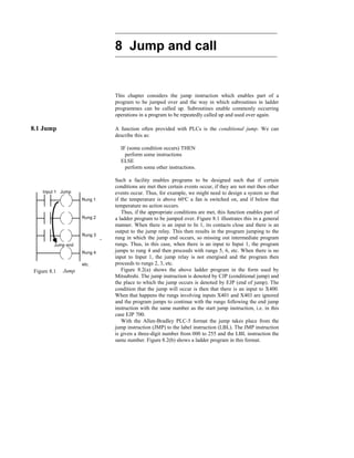
  • 1. 8 Jump and call This chapter considers the jump instruction which enables part of a program to be jumped over and the way in which subroutines in ladder programmes can be called up. Subroutines enable commonly occurring operations in a program to be repeatedly called up and used over again. 8.1 Jump A function often provided with PLCs is the conditional jump. We can describe this as: IF (some condition occurs) THEN perform some instructions ELSE perform some other instructions. Such a facility enables programs to be designed such that if certain conditions are met then certain events occur, if they are not met then other events occur. Thus, for example, we might need to design a system so that if the temperature is above 60o C a fan is switched on, and if below that temperature no action occurs. Thus, if the appropriate conditions are met, this function enables part of a ladder program to be jumped over. Figure 8.1 illustrates this in a general manner. When there is an input to In 1, its contacts close and there is an output to the jump relay. This then results in the program jumping to the rung in which the jump end occurs, so missing out intermediate program rungs. Thus, in this case, when there is an input to Input 1, the program jumps to rung 4 and then proceeds with rungs 5, 6, etc. When there is no input to Input 1, the jump relay is not energised and the program then proceeds to rungs 2, 3, etc. Figure 8.2(a) shows the above ladder program in the form used by Mitsubishi. The jump instruction is denoted by CJP (conditional jump) and the place to which the jump occurs is denoted by EJP (end of jump). The condition that the jump will occur is then that there is an input to X400. When that happens the rungs involving inputs X401 and X403 are ignored and the program jumps to continue with the rungs following the end jump instruction with the same number as the start jump instruction, i.e. in this case EJP 700. With the Allen-Bradley PLC-5 format the jump takes place from the jump instruction (JMP) to the label instruction (LBL). The JMP instruction is given a three-digit number from 000 to 255 and the LBL instruction the same number. Figure 8.2(b) shows a ladder program in this format. Input 1 Jump Jump end Rung 1 Rung 2 Rung 3 Rung 4 etc. Figure 8.1 Jump
  • 2. X400 X401 X402 Y430 Y431 CJP 700 EJP 700 Input 1 Input 2 Input 3 Output 1 Output 2 Jump between these rungs of the program if input 1 occurs JMP LBL I:012/10 I:012/11 I:012/12 010 010 O:012/10 O:012/11 O:012/12 Jump if input Input Jump Label Output I:012/10 occurs (a) (b) Figure 8.2 Jump: (a) Mitsubishi program, (b) Allen-Bradley program With Siemens’ programs, conditional jumps are represented as shown in Figure 8.3, there being a jump instruction JMP which is executed if the input is a 1 and another jump instruction JMPN which is executed if the input is 0. The end of both instructions is the label DEST. JMP Jump if input 1 JMPN Jump if input 0 DEST End of jump Figure 8.3 Siemens’ jump instructions 8.1.1 Jumps within jumps Jumps within jumps are possible. For example, we might have the situation shown in Figure 8.4. If the condition for the jump instruction 1 is realised then the program jumps to rung 8. If the condition is not met then the program continues to rung 3. If the condition for the jump instruction 2 is realised then the program jumps to rung 6. If the condition is not met then the program continues through the rungs. Thus if we have an input to In 1, the rung sequence is rung 1, 8, etc. If we have no input to In 1 but an input to In 3, then the rung sequence is 1, 2, 6, 7, 8, etc. If we have no input to In 1 and no input to In 3, the rung sequence is 1, 2, 3, 4, 5, 6, 7, 8, etc. The jump instruction enables different groups of program rungs to be selected, depending on the conditions occurring. Jump and call 155
  • 3. Rung 1 Rung 2 Rung 3 Rung 4 Rung 5 Rung 6 Rung 7 Rung 8 Jump 1 Jump 2 In 1 In 3 Jump 2 end Jump 1 end If In 1 If In 3 Figure 8.4 Jumps within jumps 8.2 Subroutines Subroutines are small programs to perform specific tasks which can be called for use in larger programs. Thus with a Mitsubishi program we might have the situation shown in Figure 8.5(a). When input 1 occurs, the subroutine P is called. This is then executed, the instruction SRET indicating its end and the point at which the program returns to the main program. To clearly indicate where the main program ends the FEND instruction is used. With Allen-Bradley, subroutines are called by using a jump-to- subroutine JSR instruction, the start of the subroutine being indicated by SBR and its end and point of return to the main program by RET (Figure 8.5(b)). With Siemens a similar format can be adopted, using CALL to call up a subroutine block and RET to indicate the return instruction to the main program. However, a function box approach (Figure 8.6) can be used and is particularly useful where there is a library of subroutine functions to be called. If the EN (enable) block input is connected directly to the left power rail then the call is without conditions and always executed. If there is a logic operation preceding EN then the block call is only executed if the logic condition is fulfilled, in Figure 8.6 this is closure of contacts of Input 1. Several blocks can be connected in series by connecting the ENO, enable output, of one to the EN input of the next. 156 Programmable Logic Controllers
  • 4. Input 1 CALL P Main program and Call to subroutine etc. FEND End of main program ; Subroutine etc. SRET Subroutine END End of entire program End of subroutine and return to main program JSR etc Jump to subroutine Main program SBR RET Subroutine Return to main program (a) return point after subroutin (b) conditional on Input 1 Input 1 conditional on Input 1 Figure 8.5 (a) Subroutine call with Mitsubishi PLC, (b) jump to subroutine call with Allen-Bradley PLC Subroutine block FCx Return to main program FCx EN IN1 IN2 OUT ENO enabled when input to EN Main program prior to call Processing of the block parameters Output when IN1 AND IN2 Input 1 Figure 8.6 Call to subroutine block with Siemens PLC Problems Questions 1 to 4 have four answer options: A, B, C or D. Choose the correct answer from the answer options. Problems 1 and 2 refer to Figure 8.7 which shows a ladder diagram with inputs In 1, In 2, In 3 and In 4, outputs Out 1, Out 2, Out 3 and Out 4 and a Jump instruction. 1 For the ladder diagram shown in Figure 8.8, for output Out 1 to occur: Jump and call 157
  • 5. A Only input In 1 must occur B Both inputs In 1 and In 2 must occur C Input In 1 must not occur and input 2 must occur D Both inputs In 1 and In 2 must not occur 2 Decide whether each of these statements is True (T) or False (F). For the ladder diagram shown in Figure 8.8, following input In 1: (i) Output 1 occurs. (ii) Output 3 occurs. A (i) T (ii) T B (i) T (ii) F C (i) F (ii) T D (i) F (ii) F Problems 3 and 4 refer to Figure 8.8 which shows a ladder diagram with inputs In 1, In 2, and In 3, outputs Out 1, Out 2, Out 3 and a jump-to-subroutine instruction. 3 Decide whether each of these statements is True (T) or False (F). For the ladder diagram shown in Figure 8.8: (i) After input In 1 occurs output Out 2 occurs. (ii) After output 3 occurs the program waits for input In 2 before proceeding A (i) T (ii) T B (i) T (ii) F C (i) F (ii) T D (i) F (ii) F 4 Decide whether each of these statements is True (T) or False (F). For the ladder diagram shown in Figure 8.8: (i) When input In 2 occurs, outputs 1 and 2 occur. (ii) When input In 3 occurs, output 3 occurs. A (i) T (ii) T B (i) T (ii) F C (i) F (ii) T D (i) F (ii) F 158 Programmable Logic Controllers JMP LBL In 1 Jump 1 Label 1 Out 3 In 2 In 3 Out 1 Out 2 In 4 Out 4 Figure 8.7 Problems 1 and 2 JSR SBR RET In 1 In 2 In 3 Out 1 Out 2 Out 3 Figure 8.8 Problems 3 and 4
  • 6. 9 Timers In many control tasks there is a need to control time. For example, a motor or a pump might need to be controlled to operate for a particular interval of time, or perhaps be switched on after some time interval. PLCs thus have timers as built-in devices. Timers count fractions of seconds or seconds using the internal CPU clock. This chapter shows how such timers can be programmed to carry out control tasks. 9.1 Types of timers PLC manufacturers differ on how timers should be programmed and hence how they can be considered. A common approach is to consider timers to behave like relays with coils which when energised result in the closure or opening of contacts after some preset time. The timer is thus treated as an output for a rung with control being exercised over pairs of contacts elsewhere (Figure 9.1(a)). This is the predominant approach used in this book. Some treat a timer as a delay block which when inserted in a rung delays signals in that rung reaching the output (Figure 9.1(b)). There are a number of different forms of timers that can be found with PLCs. With small PLCs there is likely to be just one form, the on-delay timers. These are timers which come on after a particular time delay (Figure 9.2(a)). Off-delay timers are on for a fixed period of time before turning off (Figure 9.2(b)). Another type of timer that occurs is the pulse timer. This timer switches on or off for a fixed period of time (Figure 9.2(c)). Figure 9.3 shows the IEC 1131-3 standard symbols for timers. TON is used to denote on-delay, TOF off-delay. TP pulse timers. On-delay is also represented by T 0 and off-delay by 0 T. Input Timer (a) On-delay timer Input Timer (a) Off-delay timer Input Timer (c) Pulse timer output output output Figure 9.2 Timers: (a) on-delay, (b) off-delay, (c) pulse TON BOOL TIME BOOL TIME IN PT Q ET On-delay timer TOF BOOL TIME BOOL TIME IN PT Q ET Off-delay timer TP BOOL TIME BOOL TIME IN PT Q ET Pulse timer Figure 9.3 IEC 1131-1 standards. BOOL indicates a Boolean input/output, i.e. on/off. IN is the input. Q is the output. ET is the elapsed time output. PT is the input used to specify the time. (a) Timer coil Timer contacts Time delay before activated Timer Time delay before input signal reaches output (b) Figure 9.1 Treatment of timers
  • 7. The time duration for which a timer has been set is termed the preset and is set in multiples of the time base used. Some time bases are typically 10 ms, 100 ms, 1 s, 10 s and 100 s. Thus a preset value of 5 with a time base of 100 ms is a time of 500 ms. For convenience, where timers are involved in this text, a time base of 1 s has been used. 9.2 Programming timers All PLCs generally have delay-on timers, small PLCs possibly having only this type of timer. Figure 9.4(a) shows a ladder rung diagram involving a delay-on timer. Figure 9.4(a) is typical of Mitsubishi. The timer is like a relay with a coil which is energised when the input In 1 occurs (rung 1). It then closes, after some preset time delay, its contacts on rung 2. Thus the output occurs some preset time after the input In 1 occurs. Figure 9.4(b) shows the timer to be a delay item in a rung, rather than as a relay, the example being for Siemens. When the signal at the timer’s start input changes from 0 to 1, the timer starts and runs for the programmed duration, giving its output then to the output coil. The time value (TV) output can be used to ascertain the amount of time remaining at any instant. A signal input of 1 at the reset input resets the timer whether it is running or not. Techniques for the entry of preset time values vary. Often it requires the entry of a constant K command followed by the time interval in multiples of the time base used. Figure 9.4(c), (d) and (e) shows ladder diagrams Telemecanique, Toshiba and Allen-Bradley. X400 T450 K5 T450 Y430 LD OUT T450 X400 K 5 LD T450 OUT Y430 (a) (b) T0 I0.0 Q2.0 KT5.2 A LKT SR A = I0.0 5.2 T0 T0 Q2.0 TON S Q TV R BI BCD Input In 1 Timer Timer Output Input In 1 S is Boolean start input. TV is duration of time specification. R is Boolean reset. BI is current time value in binary word. BCD is current time value in BCD word Q is Boolean output, indicating state of timer. I0,0 T0 1 s = TB P = 10 O0,0 00010 TON T001 X001 Y020 (c) (d) TON I:012/01 TIMER ON TIMER T4:0 TIME BASE 1:0 PRESET 5 (e) DN EN Input EN DN Time Time Time T4.0 Timer Input O:012/10 Output The enbable bit EN is set to 1 when there is a logic path to the time. The done bit DN indicates the status of the timer and is set to 1 when the accumulated value equals the preset value. Figure 9.4 Timers: (a) Mitsubishi, (b) Siemens, (c) Telemecanique, (d) Toshiba, (e) Allen-Bradley 160 Programmable Logic Controllers
  • 8. 9.2.1 Sequencing As an illustration of the use of a timer, consider the ladder diagram shown in Figure 9.5(a). When the input In 1 is on, the output Out 1 is switched on. The contacts associated with this output then start the timer. The contacts of the timer will close after the preset time delay, in this case 5.5 s. When this happens, output Out 2 is switched on. Thus, following the input In 1, Out 1 is switched on and followed 5.5 s later by Out 2. This illustrates how timed sequence of outputs can be achieved. Figure 9.5(b) shows the same operation where the format used by the PLC manufacturer is for the timer to institute a signal delay. In 1 Out 1 Out 1 Timer Timer Out 2 Preset to 5.5 In 1 Out 1 Out 1 TON Out 2 Timer Preset to 5.5 s IN Q (a) (b) Figure 9.5 Sequenced outputs Figure 9.6 shows two versions of how timers can be used to start three outputs, e.g. three motors, in sequence following a single start button being pressed. In (a) the timers are programmed as coils, whereas in (b) they are programmed as delays. When the start push button is pressed there is an output from internal relay IR1. This latches the start input. It also starts both the timers, T1 and T2, and motor 1. When the preset time for timer 1 has elapsed then its contacts close and motor 2 starts. When the preset time for timer 2 has elapsed then its contacts close and motor 3 starts. The three motors are all stopped by pressing the stop push button. Since this is seen as a complete program, the end instruction has been used. 9.2.2 Cascaded timers Timers can be linked together, the term cascaded is used, to give longer delay times than are possible with just one timer. Figure 9.7(a) shows the ladder diagram for such an arrangement. Thus we might have timer 1 with a delay time of 999 s. This timer is started when there is an input to In 1. When the 999 s time is up, the contacts for timer 1 close. This then starts timer 2. This has a delay of 100 s. When this time is up, the timer 2 contacts close and there is an output from Out 1. Thus the output occurs 1099 s after the input to In 1. Figure 9.7(b) shows the Mitsubishi version of this ladder diagram and the program instructions for that ladder. Timers 161
  • 9. END TON TON Motor 1 Motor 2 Motor 3 T1 T2 IR2 IR3 Start Stop IR1 IR1 IR1 IR1 IR1 IR2 IR3 END Motor 1 Motor 2 Motor 3 Start Stop IR1 IR1 IR1 IR1 IR1 T1 T2 T1 T2 (a) (b) Start T1 T2 Motor 1 Motor 2 Motor 3 Stop Timing diagram IN Q IN Q Figure 9.6 Motor sequence In 1 Timer 1 Timer 2 Timer 2 Out 1 Preset 999 Preset 100 T450 K999 Timer 1 X400 T450 T451 K100 T451 Y430 LD OUT K LD OUT K LD OUT X400 T450 999 T450 T451 100 T451 Y430 (a) (b) Figure 9.7 Cascaded timers 9.2.3 On off cycle timer Figure 9.8 shows how on-delay timers can be used to produce an on off cycle timer. The timer is designed to switch on an output for 5 s, then off for 5 s, then on for 5 s, then off for 5 s, and so on. When there is an input to In 1 and its contacts close, timer 1 starts. Timer 1 is set for a delay of 5 s. After 5 s, it switches on timer 2 and the output Out 1. Timer 2 has a delay of 5 s. After 5 s, the contacts for timer 2, which are normally closed, 162 Programmable Logic Controllers
  • 10. open. This results in timer 1, in the first rung, being switched off. This then causes its contacts in the second rung to open and switch off timer 2. This results in the timer 2 contacts resuming their normally closed state and so the input to In 1 causes the cycle to start all over again. In 1 T2 T1 K5 T1 T1 T2 K5 Out 1 In1 T1 T2 Out 1 5 s 5 s 5 s Time Time Time Time Figure 9.8 On off cycle timer Figure 9.9 shows how the above ladder program would appear in the format used with a timer considered as a delay, rather than as a coil. This might, for example, be with Siemens or Toshiba. When input In 1 closes, the timer T1 starts. After its preset time, there is an output to Out 1 and timer T2 starts. After its preset time there is an output to the internal relay IR1. This opens its contacts and stops the output from Out 1. This then switches off timer T2. The entire cycle can then repeat itself. In 1 T1 IR1 T1 Out 1 T2 IR1 TON TON IN Q IN Q Figure 9.9 On–off cycle timer 9.3 Off-delay timers Figure 9.10 shows how a on-delay timer can be used to produce an off-delay timer. With such an arrangement, when there is a momentary input to In 1, both the output Out 1 and the timer are switched on. Because the input is latched by the Out 1 contacts, the output remains on. After the preset timer time delay, the timer contacts, which are normally closed, open and switch off the output. Thus the output starts as on and remains on until the time delay has elapsed. Timers 163
  • 11. In 1 Timer Out 1 Timer Out 1 In 1 Out 1 Timer Time Time Time Figure 9.10 Off-delay timer Some PLCs have, as well as on-delay timers, built-in off-delay timers and thus there is no need to use an on-delay timer to produce an off-delay timer. Figure 9.11 illustrates this for a Siemens PLC, giving the ladder diagram and the instruction list. Note that with this manufacturer, the timer is considered to be a delay item in a rung, rather than as a relay. In the rectangle symbol used for the timer, the 0 precedes the T and indicates that it is an on-delay timer. I0.0 T0 Q2.0 KT5.2 A LKT SF A = I0.0 5.2 T0 T0 Q2.0 TOF S Q TV Figure 9.11 Off-delay timer As an illustration of the use of an off-delay timer, consider the Allen- Bradley program shown in Figure 9.12. TOF is used to indicate that it is an off-delay, rather than on-delay (TON) timer. The time base is set to 1:0 which is 1 s. The preset is 10 so the timer is preset to 10 s. TOF TIMER OFF DELAY TIMER T4:1 TIME BASE 1:0 PRESET 10 EN DN T4:1 EN T4:1 TT T4:1 DN T4:1 DN I:012/01 O:013/01 O:013/02 O:013/03 O:013/04 Rung 1 Rung 2 Rung 3 Rung 4 Rung 5 I:012/01 O:013/01 O:013/02 O:013/03 O:013/04 Time Time Time Time 10 s Time EN DN Time Time Figure 9.12 Application of an off-delay timer 164 Programmable Logic Controllers
  • 12. In the first rung, the output of the timer is taken from the EN (for enable) contacts. This means that there is no time delay between an input to I:012/01 and the EN output. As a result the EN contacts in rung 2 close immediately there is an I:012/01 input. Thus there is an output from O:013/01 immediately the input I:012/01 occurs. The TT (for timer timing) contacts in rung 3 are energised just while the timer is running. Because the timer is an off-delay timer, the timer is turned on for 10 s before turning off. Thus the TT contacts will close when the set time of 10 s is running. Hence output O:012/02 is switched on for this time of 10 s. The DN (for done) contacts which are normally closed, open after the 10 s and so output O:013/03 comes on after 10 s. The DN contacts which are normally open, close after 10 s and so output O:013/04 goes off after 10 s. 9.4 Pulse timers Pulse timers are used to produce a fixed duration output from some initiating input. Figure 9.13(a) shows a ladder diagram for a system that will give an output from Out 1 for a predetermined fixed length of time when there is an input to In 1, the timer being one involving a coil. There are two outputs for the input In 1. When there is an input to In 1, there is an output from Out 1 and the timer starts. When the predetermined time has elapsed, the timer contacts open. This switches off the output. Thus the output remains on for just the time specified by the timer. In 1 Timer Timer Out 1 In 1 Timer contacts Closed Open Out 1 Time Time Time (a) (b) In 1 TON Timer Internal relay Internal relay Out 1 Figure 9.13 Pulse-on timer Figure 9.13(b) shows an equivalent ladder diagram to Figure 9.13(a) but employing a timer which produces a delay in the time taken for a signal to reach the output. In Figure 9.13, the pulse timer has an output switched on by an input for a predetermined time, then switching off. Figure 9.14 shows another pulse timer that switches an output on for a predetermined time after the input ceases. This uses a timer and two internal relays. When there is an Timers 165
  • 13. input to In 1, the internal relay IR 1 is energised. The timer does not start at this point because the normally closed In 1 contacts are open. The closing of the IR 1 contacts means that the internal relay IR 2 is energised. There is, however, no output from Out 1 at this stage because, for the bottom rung, we have In 1 contacts open. When the input to In 1 ceases, both the internal relays remain energised and the timer is started. After the set time, the timer contacts, which are normally closed, open and switch off IR 2. This in turn switches off IR 1. It also, in the bottom rung, switches off the output Out 1. Thus the output is off for the duration of the input, then being switched on for a predetermined length of time. In 1 In 1 Timer IR 2 IR 1 IR 1 Timer IR 2 In 1 IR 2 Out 1 In 1 IR 1 IR 2 Out 1 Timer Time Time Time Time Time Figure 9.14 Pulse timer on, when output ceases 9.5 Programming examples Consider a program (Figure 9.15) that could be used to flash a light on and off as long as there is some output occurring. Thus we might have both timer 0 and timer 1 set to 1 s. When the output occurs, then timer 0 starts and switches on after 1 s. This closes the timer 0 contacts and starts timer 1. This switches on after 1 s and, in doing so, switches off timer 0. In so doing, it switches off itself. The lamp is only on when timer 0 is on and so we have a program to flash the lamp on and off as long as there is an output. Timer 1 TON Timer 1 Timer 0 Timer 0 TON Lamp Timer 0 Output END Figure 9.15 Flashing light 166 Programmable Logic Controllers
  • 14. As an illustration of programming involving timers consider the sequencing of traffic lights to give the sequence red only, red plus amber, green, amber, then repeat itself. A simple system might just have the sequence triggered by time, with each of the possible states occurring in sequence for a fixed amount of time. Figure 9.16 shows the sequential function chart and a possible ladder program to give the sequence. State 0 Red only State 1 Red + amber State 2 Green only State 3 Amber only Time 2 min Time 20 s Time 2 min Time 20 s Start Start Red Red Red TON Timer 1 2 min Red Amber Amber TON Timer 2 20 s Green Green TON Timer 3 2 min Amber State 3 State 2 State 1 State 0 END Red Amber TON Timer 3 20 s Start End IN Q IN Q IN Q IN Q Figure 9.16 Traffic light sequence Problems Questions 1 to 19 have four answer options: A, B, C or D. Choose the correct answer from the answer options. Problems 1 to 3 refer to Figure 9.17 which shows a ladder diagram with an on-delay timer, an input In 1 and an output Out 1. 1 Decide whether each of these statements is True (T) or False (F). When there is an input to In 1 in Figure 9.17: (i) The timer starts. (ii) There is an output from Out 1. A (i) T (ii) T B (i) T (ii) F C (i) F (ii) T D (i) F (ii) F Timers 167
  • 15. 2 Decide whether each of these statements is True (T) or False (F). The timer in Figure 9.17 starts when: (i) There is an output. (ii) The input ceases. A (i) T (ii) T B (i) T (ii) F C (i) F (ii) T D (i) F (ii) F 3 Decide whether each of these statements is True (T) or False (F). When there is an input to In 1, the output is switched: (i) On for the time for which the timer was preset. (ii) Off for the time for which the timer was preset. A (i) T (ii) T B (i) T (ii) F C (i) F (ii) T D (i) F (ii) F Problems 4 to 6 refer to Figure 9.18 which shows two alternative versions of a ladder diagram with two inputs In 1 and In 2, two outputs Out 1 and Out 2 and an on-delay timer. In 1 In 2 Out 1 Out 1 Timer Timer Out 2 In 1 In 2 Out 1 Timer TON Out 2 Figure 9.18 Problems 4 to 6 4 Decide whether each of these statements is True (T) or False (F). When there is just an input to In 1: (i) The timer starts. (ii) There is an output from Out 2. A (i) T (ii) T B (i) T (ii) F C (i) F (ii) T D (i) F (ii) F 5 Decide whether each of these statements is True (T) or False (F). When there is just an input to In 2: (i) The timer starts. (ii) There is an output from Out 2. 168 Programmable Logic Controllers In 1 Timer In 1 Timer Out 1 Out 1 Figure 9.17 Problems 1 to 3
  • 16. A (i) T (ii) T B (i) T (ii) F C (i) F (ii) T D (i) F (ii) F 6 Decide whether each of these statements is True (T) or False (F). When there is an input to In 1 and no input to In 2, there is an output from Out 2 which: (i) Starts immediately. (ii) Ceases after the timer preset time. A (i) T (ii) T B (i) T (ii) F C (i) F (ii) T D (i) F (ii) F 7 The program instruction list for a Mitsubishi PLC is: LD X400, OUT T450, K 6, LD T450, OUT Y430. An input to X400 gives: A An output which is on for 6 s then off for 6 s. B An output which lasts for 6 s. C An output which starts after 6 s. D An output which is off for 6 s, then on for 6 s. 8 The program instruction list for a Telemecanique PLC is: L I0,0, = T0, L T0, = O0,0. When there is an input to I0,0 there is: A An output which is on for 6 s then off for 6 s. B An output which lasts for 6 s. C An output which starts after 6 s. D An output which is off for 6 s, then on for 6 s. Problems 9 and 10 refer to the program instruction list for a Mitsubishi PLC: LD X400, OR Y430, ANI T450, OUT Y430, LD X401, OR M100, AND Y430, OUT T450, K 10, OUT M100. 9 Decide whether each of these statements is True (T) or False (F). When there is a momentary input to X400: (i) The output from Y430 starts. (ii) The output from Y430 ceases after 10 s. A (i) T (ii) T B (i) T (ii) F C (i) F (ii) T D (i) F (ii) F 10 Decide whether each of these statements is True (T) or False (F). The output from Y430: (i) Starts when there is a momentary input to X401. (ii) Ceases 10 s after the input to X401. Timers 169
  • 17. A (i) T (ii) T B (i) T (ii) F C (i) F (ii) T D (i) F (ii) F Problems 11 and 12 refer to Figure 9.19 which shows a system with an input In 1, an on-delay timer and an output Out 1. The timer is set for a time of 6 s. The graph shows how the signal to the input varies with time. In 1 Timer Timer Out 1 In 1 Time Figure 9.19 Problems 11 and 12 11 Decide whether each of these statements is True (T) or False (F). The output from Out 1: (i) Starts when the input starts. (ii) Ceases 6 s after the start of the input. A (i) T (ii) T B (i) T (ii) F C (i) F (ii) T D (i) F (ii) F 12 Decide whether each of these statements is True (T) or False (F). The timer contacts: (i) Remain closed for 6 s after the start of the input. (ii) Open 6 s after the input starts. A (i) T (ii) T B (i) T (ii) F C (i) F (ii) T D (i) F (ii) F Problems 13 to 15 refer to Figure 9.20 which shows a ladder program for a Toshiba PLC involving internal relays, denoted by the letter R, and a TON timer with a preset of 20 s. 13 Decide whether each of these statements is True (T) or False (F). The internal relay R000 in Figure 9.20: (i) Is used to latch the input X001. (ii) Is used to start the timer T001. A (i) T (ii) T B (i) T (ii) F C (i) F (ii) T D (i) F (ii) F 170 Programmable Logic Controllers
  • 18. TON T001 X001 X002 R000 R000 R000 Y020 R001 R001 Y021 Figure 9.20 Problems 13 to 15 14 Decide whether each of these statements is True (T) or False (F). With no input to X002 in Figure 9.20, the output Y020 is: (i) Energised when there is an input to X001. (ii) Ceases when there is no input to X001. A (i) T (ii) T B (i) T (ii) F C (i) F (ii) T D (i) F (ii) F 15 Decide whether each of these statements is True (T) or False (F). With no input to X002 in Figure 9.20: (i) The output Y021 is switched on 20 s after the input X001. (ii) The output Y020 is switched off 20 s after the input X001. A (i) T (ii) T B (i) T (ii) F C (i) F (ii) T D (i) F (ii) F Problems 16 to 19 refer to Figure 9.21 which shows an Allen-Bradley program and Figure 9.22 which shows a number of time charts for a particular signal input to I:012/01. 16 For the input shown in Figure 9.22, which is the output from O:013/01? 17 For the input shown in Figure 9.22, which is the output from O:013/02? 18 For the input shown in Figure 9.22, which is the output from O:013/03? Timers 171
  • 19. TON TIMER ON DELAY TIMER T4:1 TIME BASE 1:0 PRESET 50 EN DN I:012/01 T4:1 EN T4:1 TT T4:1 DN T4:1 DN O:013/01 O:013/02 O:013/03 O:013/04 Input A B C D Time Time Time Time Time 50 s Figure 9.21 Problems 16 to 19 Figure 9.22 Problems 16 to 19 19 For the input shown in Figure 9.22, which is the output from O:013/04? 20 Devise ladder programs for systems that will carry out the following tasks: (a) Switch on an output 5 s after receiving an input and keep it on for the duration of that input. (b) Switch on an output for the duration of the input and then keep it on for a further 5 s. (c) Switch on an output for 5 s after the start of an input signal. 172 Programmable Logic Controllers
  • 20. 10 Counters Counters are provided as built-in elements in PLCs and allow the number of occurrences of input signals to be counted. This might be where items have to be counted as they pass along a conveyor belt, or the the number of revolutions of a shaft, or perhaps the number of people passing through a door. This chapter describes how such counters can be programmed. 10.1 Forms of counter A counter is set to some preset number value and, when this value of input pulses has been received, it will operate its contacts. Thus normally open contacts would be closed, normally closed contacts opened. There are two types of counter, though PLCs may not include both types. These are down-counters and up-counters. Down-counters count down from the preset value to zero, i.e. events are subtracted from the set value. When the counter reaches the zero value, its contacts change state. Most PLCs offer down counting. Up-counters count from zero up to the preset value, i.e. events are added until the number reaches the preset value. When the counter reaches the set value, its contacts change state. Different PLC manufacturers deal with counters in slightly different ways. Some count down (CTD), or up (CTU), and reset and treat the counter as though it is a relay coil and so a rung output. In this way, counters can be considered to consist of two basic elements: one relay coil to count input pulses and one to reset the counter, the associated contacts of the counter being used in other rungs. Figure 10.1(a) illustrates this. Mitsubishi is an example of this type of manufacturer. Others treat the counter as an intermediate block in a rung from which signals emanate when the count is attained. Figure 10.1(b) illustrates this. Siemens is an example of this type of manufacturer. Counter Counter RST CTD Counter Activated when zero reached after counting R CU PV Output when set count reached after counting Counter Q CV CTU PV CD LD Output when zero reached after counting down Counter Q CV CTD Counter Counter RST CTU Counter Activated when set count reached after down from set value counting up from zero from set value up from zero (a) (b) Figure 10.1 Forms of representation of counters. In (a) RST is reset. In (b), the IEC 1131-3 representation, CD is count down input, LD is for loading the input, PV is for the preset value, CV the current count value, CU is count up input, and R is for the reset input.
  • 21. 10.2 Programming Figure 10.2 shows a basic counting circuit. When there is a pulse input to In 1, the counter is reset. When there is an input to In 2, the counter starts counting. If the counter is set for, say, 10 pulses, then when 10 pulse inputs have been received at In 2, the counter’s contacts will close and there will be an output from Out 1. If at any time during the counting there is an input to In 1, the counter will be reset and start all over again and count for 10 pulses. In 1 Counter RST Counter In 2 Counter Out 1 In 1 In 2 Out 1 Time Time Time Counter CU CTU Q R PV CV In 1 In 2 Out 1 CU Figure 10.2 Basic counter program Figure 10.3(a) shows how the above program, and its program instruction list, would appear with a Mitsubishi PLC. The reset and counting elements are combined in a single box spanning the two rungs. You can consider the rectangle to be enclosing the two counter ( ) outputs in Figure 10.2. The count value is set by a K program instruction. Figure 10.3(b) shows the same program with a Siemens PLC. With this ladder program, the counter is considered to be a delay element in the output line (as in Figure 10.1(b)). The counter is reset by an input to I0.1 and counts the pulses into input I0.0. The CU indicates that it is a count-up counter, a CD would indicate a count-down counter. The counter set value is indicated by the LKC number. Figure 10.3(c) is the program for Toshiba and Figure 10.3(d) for Allen-Bradley. 10.2.1 Counter application As an illustration of the use that can be made of a counter, consider the problem of items passing along a conveyor belt, the passage of an item past a particular point being registered by a light beam to a photoelectric cell being interrupted, and after a set number there is to be a signal sent informing that the set count has been reached and the conveyor stopped. Figure 10.4(a) shows the basic elements of a Siemens program that could be used. A reset signal causes the counter to reset and start counting again. The set signal is used to make the counter active. Figure 10.4(b) shows the basic elements of the comparable Allen-Bradley program. When the count reaches the preset value, the done bit is set to 1 and so O:013/01 occurs and the corresponding contacts are opened and the conveyor stopped. 174 Programmable Logic Controllers
  • 22. X400 X401 C460 RESET OUT C460 K10 Y430 LD RST LD OUT K LD OUT X400 C460 X401 C460 10 C460 Y430 (a) (b) C0 CU PV I0.0 I0.1 Q2.0 R Q S_CU 10 S CV CV_BCD C E Q C = count input E = enable or Q = output X000 X001 Y020 (c) CTU = count up C5:1 is counter address Preset is the preset count number Note: CTD = count down CU = output for use with count up counters and is termed the count up enable. It gives an output until the count has reached the preset value. DN = output which gives an output when the count has reached the CTU C5:1 Preset 10 O:013/01 I:012/01 C5:1 DN I:012/02 C5:1 RES DN CU I:012/01 DN output CU output I:012/02 Switched on after count of 10 Switched off by I:012/02 input (d) set value CV_BCD is count value in BCD. CV is count value in Boolean. S is SET and is used to activate the counter and is set to its starting value; with count up, this is zero. reset input Figure 10.3 (a) Mitsubishi program, (b) Siemens program, (c) Toshiba program, (b) Allen-Bradley programs Counter S_CD CD Q S PV R CV CV_BCD Set counter Quantity Input pulses Output when finished Output Conveyor Reset CTU C5:1 Preset O:013/01 C5:1 DN I:012/02 C5:1 RES DN CU (a) (b) Input pulse Counter O:013/01 Conveyor Figure 10.4 (a) Siemens, (b) Allen-Bradley counting program Counters 175
  • 23. As a further illustration of the use of a counter, consider the problem of the control of a machine which is required to direct 6 tins along one path for packaging in a box and then 12 tins along another path for packaging in another box (Figure 10.5). A deflector plate might be controlled by a photocell sensor which gives an output every time a tin passes it. Thus the number of pulses from the sensor has to be counted and used to control the deflector. Figure 10.6 shows the ladder program that could be used. Mitsubishi notation has been used. C460 K6 RESET X400 C461 X401 OUT RESET C461 K12 OUT C460 Y430 X400 C461 X401 C460 LD OR RST K LD OUT LD OUT LD OR RST K LD AND OUT X400 C461 C460 6 X401 C460 C460 Y430 X400 C461 C461 12 X401 C460 C461 Figure 10.6 Ladder program for Figure 10.5 task When there is a pulse input to X400, both the counters are reset. The input to X400 could be the push button switch used to start the conveyor moving. The input which is counted is X401. This might be an input from a photocell sensor which detects the presence of tins passing along the conveyor. C460 starts counting after X400 is momentarily closed. When C460 has counted six items, it closes its contacts and so gives an output at Y430. This might be a solenoid which is used to activate a deflector to deflect items into one box or another. Thus the deflector might be in such a position that the first six tins passing along the conveyor are deflected into the 6-pack box, then the deflector plate is moved to allow tins to pass to the 12-pack box. When C460 stops counting it closes its contacts and so allows C461 to start counting. C461 counts for 12 pulses to X401 and then closes its contacts. This results in both counters being reset and the entire process can repeat itself. Counters can be used to ensure that a particular part of a sequence is repeated a known number of times. This is illustrated by the following 176 Programmable Logic Controllers Deflector 12 tin box 6 tin box Figure 10.5 Counting task
  • 24. program which is designed to enable a three-cylinder, double solenoid- controlled arrangement (Figure 10.7(a)) to give the sequence A+, A–, A+, A–, A+, A–, B+, C+, B–, C–. The A+, A– sequence is repeated three times before B+, C+, B–, C– occur. We can use a counter to enable this repetition. Figure 10.7(b) shows a possible program. The counter only allows B+ to occur after it has received three inputs corresponding to three a– signals. B b– b+ B+ B– A a– a+ A+ A– PLC a– a+ b– b+ c+ Inputs from A+ A– B+ B– C+ C– Outputs to solenoids limit switches Power E L N Start Stop –V C c+ C+ C– c– RST Counter K3 OUT END Start Start a– A+ a+ A– a– Counter B+ C+ b+ c+ B– C– b– c+ (a) (b) Figure 10.7 (a) Three-cylinder system, (b) program Counters 177
  • 25. 10.3 Up and down counting It is possible to program up- and down-counters together. Consider the task of counting products as they enter a conveyor line and as they leave it, or perhaps cars as they enter a multi-storage parking lot and as they leave it. An output is to be triggered if the number of items/cars entering is some number greater than the number leaving, i.e. the number in the parking lot has reached a ‘saturation’ value. The output might be to illuminate a ‘No empty spaces’ sign. Suppose we use the up-counter for items entering and the count down for items leaving. Figure 10.8(a) shows the basic form a ladder program for such an application can take. When an item enters it gives a pulse on input In 1. This increases the count by one. Thus each item entering increases the accumulated count by 1. When an item leaves it gives an input to In 2. This reduces the number by 1. Thus each item leaving reduces the accumulated count by 1. When the accumulated value reaches the preset value, the output Out 1 is switched on. Figure 10.8(b) shows the implementation of this program with an Allen-Bradley program. Up-counter In 1 Down-counter In 2 In 3 Reset Out 1 Counter (a) (b) CTU CTD DN CU CD DN C5:0 C5:0 C5:0 DN RES I:012/10 I:012/11 I:013/10 O:013/10 Figure 10.8 (a) Using up- and down-counters, (b) Allen-Bradley program Up-down counters are available as single entities. Figure 10.9 shows the IEC 1131-3 standard symbol. The counter has two inputs CU and CD and counts up the number of pulses detected at the input CU and counts down the number of pulses detected at input CD. If the counter input reaches zero, the QD output is set on and the counting down stops. If the count reaches the maximum value PV, the QU output is set on and the counting up stops. CV is the count value. LD can be used to preset the counter output CV with the value PV. The reset R clears the counter input to zero. Figure 10.10 shows how the above system might appear for a Siemens PLC and the associated program instruction list. CU is the count up input and CD the count down. R is the reset. The set accumulator value is loaded via F0.0, this being an internal relay. 178 Programmable Logic Controllers CTUD QU QD CU CD R LD PV CV Figure 10.9 IEC 1131-3 standard symbol for up- down counter
  • 26. I0.0 I0.1 F0.0 I0.2 C0 CU CD S PV R QU Q2.0 The count is set to the preset value PV when the set (load) input is 1. As long as it is 1 Each input pulse to CU increments the count by 1 Each input pulse to CD decrements the count by 1 The count is reset to zero when the reset R is 1. inputs to CU and CD have no effect. Figure 10.10 Up and down counting with a Siemens PLC 10.4 Timers with counters A typical timer can count up to 16 binary bits of data, this corresponding to 32 767 base time units. Thus, if we have a time base of 1 s then the maximum time that can be dealt with by a timer is just over 546 minutes or 9.1 hours. If the time base is to be 0.1 s then the maximum time is 54.6 minutes or just short of an hour. By combining a timer with a counter, longer times can be counted. Figure 10.11 illustrates this with an Allen-Bradley program. If the timer has a time base of 1 s and a preset value of 3600, then it can count for up to 1 hour. When input I:012/01 is activated, the timer starts to time in one second increments. When the time reaches the preset value of 1 hour, the DN bit is set to 1 and the counter increments by 1. The DN bit setting to 1 also reset the timer and the timer starts to time again. When it next reaches its preset time of 1 hour, the DN bit is again set to 1 and the counter increments by 1. With the counter set to a preset value of 24, the counter DN bit is set to 1 when the count reaches 24 and the output O:013/01 is turned on. We thus have a timer which is able to count the seconds for the duration of a day and would be able to switch on some device after 24 hours. EN DN T4:0 DN I:012/01 CU DN T4:0 DN C5.0 DN O:013/01 Timer T4.0 Counter C5.0 TON Time base 1.0 Preset 3600 Accum 0 CTU Preset 24 Accum 0 Figure 10.11 Using a counter to extend the range of a timer Counters 179
  • 27. 10.5 Sequencer The drum sequencer is a form of counter that is used for sequential control. It replaces the mechanical drum sequencer that was used to control machines that have a stepped sequence of repeatable operations. One form of the mechanical drum sequencer consisted of a drum from which a number of pegs protruded (Figure 10.12). When the cylinder rotated, contacts aligned with the pegs were closed when the peg impacted on them and opened when the peg had passed. Thus for the arrangement shown in Figure 10.12, as the drum rotates, in the first step the peg for output 1 is activated, in step 2 the peg for the third output, in step 3 the peg for the second output, and so on. Different outputs could be controlled by pegs located at different distances along the drum. Another form consisted of a series of cams on the same shaft, the profile of the cam being used to switch contacts on and off. Rotation Different segment for the contacts for each of the outputs Pegs to activate contacts 1 2 3 4 5 6 7 8 Steps Figure 10.12 Drum sequencer The PLC sequencer consists of a master counter that has a range of preset counts corresponding to the different steps and so, as it progresses through the count, when each preset count is reached it can be used to control outputs. Each step in the count sequence relates to a certain output or group of outputs. The outputs are internal relays, these in turn being used to control the external output devices. Suppose we want output 1 to be switched on 5 s after the start and remain on until the time reaches 10 s, output 2 to be switched on at 10 s and remain on until 20 s, output 3 to be switched on at 15 s and remain on until 25 s, etc. We can represent the above requirements by a time sequence diagram, Figure 10.13, showing the required time sequence. 0 5 10 15 20 25 30 Outputs 1 2 3 4 Time in seconds Figure 10.13 Timing diagram We can transform the timing diagram into a drum sequence requirement. Taking each drum sequence step to take 5 s gives the 180 Programmable Logic Controllers
  • 28. requirement diagram shown in Table 10.1. Thus at step 1 we require output 1 to be switched on and to remain on until step 2. At step 2 we require output 2 to be switched on and remain on until step 4. At step 3 we require output 3 to be switched on and remain on until step 5. At step 5 we require output 4 to be switched on and remain on until step 6. Table 10.1 Sequence requirements 0 0 0 0 30 6 1 1 0 0 25 5 0 1 0 0 20 4 0 1 1 0 15 3 0 0 1 0 10 2 0 0 0 1 5 1 0 0 0 0 0 0 Output 4 Output 3 Output 2 Output 1 Time (s) Step With a PLC, such as a Toshiba, the sequencer is set up by switching on the Step Sequence Initialize (STIZ) function block R500 (Figure 10.14). This sets up the program for step 1 and R501. This relay then switches on output Y020. The next step is the switching on of R502. This switches on the output Y021 and also a delay-on timer so that R503 is not switched on until the timer has timed out. Then R503 switches on Y022 and also the next step in the sequence. X000 to switch on sequencer STIZ R500 R500 R501 R501 R502 R501 Y020 R502 TON T000 R503 R503 Y022 R503 R504 and so on R502 Y021 Figure 10.14 Sequencer with a Toshiba PLC Counters 181
  • 29. With the Allen-Bradley form of PLC the sequencer is programmed by using a sequence of binary words in the form of the outputs required, e.g. those listed in Table 10.1. Thus we would have the following binary word sequence put into the program using the programming device. 0000 0001 0010 0110 0100 0100 0000 Input 4 Input 3 Input 2 Input 1 Problems Questions 1 to 19 have four answer options: A, B, C or D. Choose the correct answer from the answer options. Problems 1 to 3 refer to Figure 10.15 which shows a ladder diagram with a counter, two inputs In 1 and In 2 and an output Out 1. 1 Decide whether each of these statements is True (T) or False (F). For the ladder diagram shown in Figure 10.15, when the counter is set to 5, there is an output from Out 1 every time: (i) In 1 has closed 5 times. (ii) In 2 has closed 5 times. A (i) T (ii) T B (i) T (ii) F C (i) F (ii) T D (i) F (ii) F 2 Decide whether each of these statements is True (T) or False (F). For the ladder diagram shown in Figure 10.15: (i) The first rung gives the condition required to reset the counter. (ii) The second rung gives the condition required to generate pulses to be counted. A (i) T (ii) T B (i) T (ii) F C (i) F (ii) T D (i) F (ii) F 3 Decide whether each of these statements is True (T) or False (F). In Figure 10.15, when there is an input to In 1: (i) The counter contacts in the third rung close. (ii) The counter is ready to start counting the pulses from In 2. 182 Programmable Logic Controllers In 1 Counter RST Counter In 2 Counter Out 1 First rung Second rung Third rung Figure 10.15 Problems 1 to 3
  • 30. A (i) T (ii) T B (i) T (ii) F C (i) F (ii) T D (i) F (ii) F Problems 4 and 5 refer to the following program instruction list involving a down-counter: Y430 OUT 460 LD 5 K C460 OUT X401 LD C460 RST X400 LD 4 Decide whether each of these statements is True (T) or False (F). Every time there is an input to X401: (i) The count accumulated by the counter decreases by 1. (ii) The output is switched on. A (i) T (ii) T B (i) T (ii) F C (i) F (ii) T D (i) F (ii) F 5 Decide whether each of these statements is True (T) or False (F). When there is an input to X400, the counter: (i) Resets to a value of 5. (ii) Starts counting from 0. A (i) T (ii) T B (i) T (ii) F C (i) F (ii) T D (i) F (ii) F Problems 6 and 7 refer to the following program instruction list involving a counter C0: 2.00 Q C0 R I0.1 A 5 LKC C0 CD I0.0 A 6 Decide whether each of these statements is True (T) or False (F). Every time there is an input to I0.0: (i) The count accumulated by the counter decreases by 1. (ii) The output is switched on. Counters 183
  • 31. A (i) T (ii) T B (i) T (ii) F C (i) F (ii) T D (i) F (ii) F 7 Decide whether each of these statements is True (T) or False (F). When there is an input to I0.1, the counter: (i) Resets to a value of 5. (ii) Starts counting from 0. A (i) T (ii) T B (i) T (ii) F C (i) F (ii) T D (i) F (ii) F Problems 8 and 9 refer to Figure 10.16 which shows a down-counter C460 controlled by two inputs X400 and X401, there being an output from Y430. X400 X401 C460 RESET OUT C460 K10 Y430 Figure 10.16 Problems 8 and 9 8 Decide whether each of these statements is True (T) or False (F). When there is an input to X400, the counter: (i) Resets to a value of 0. (ii) Starts counting. A (i) T (ii) T B (i) T (ii) F C (i) F (ii) T D (i) F (ii) F 9 Decide whether each of these statements is True (T) or False (F). Every time there is an input to X401, the counter: (i) Gives an output from Y430. (ii) Reduces the accumulated count by 1. A (i) T (ii) T B (i) T (ii) F C (i) F (ii) T D (i) F (ii) F 184 Programmable Logic Controllers
  • 32. Problems 10 to 12 refer to Figure 10.17 which shows a ladder diagram involving a counter C460, inputs X400 and X401, internal relays M100 and M101, and an output Y430. RESET C460 K10 OUT X400 M101 M100 X400 M101 C460 X401 M100 Y430 M100 C460 Y430 Figure 10.17 Problems 10 to 12 10 Decide whether each of these statements is True (T) or False (F). For the output Y430: (i) It switches on the tenth pulse to X400. (ii) It switches off at the start of the eleventh pulse to X400. A (i) T (ii) T B (i) T (ii) F C (i) F (ii) T D (i) F (ii) F 11 Decide whether each of these statements is True (T) or False (F). When there is an input to X400: (i) The internal relay M100 is energised. (ii) The internal relay M101 is energised. A (i) T (ii) T B (i) T (ii) F C (i) F (ii) T D (i) F (ii) F 12 Decide whether each of these statements is True (T) or False (F). Counters 185
  • 33. There is an output from Y430 as long as: (i) The C460 contacts are closed. (ii) Y430 gives an output and M100 is energised. A (i) T (ii) T B (i) T (ii) F C (i) F (ii) T D (i) F (ii) F 13 Decide whether each of these statements is True (T) or False (F). Figure 10.18 shows a counter program in Siemens format. After 10 inputs to I0.0: (i) The lamp comes on. (ii) The motor starts. A (i) T (ii) T B (i) T (ii) F C (i) F (ii) T D (i) F (ii) F Problems 14 and 15 refer to Figure 10.19 which shows a Siemens program involving an up- and down-counter. I0.0 I0.1 F0.0 I0.2 50 C0 CU CD S PV R Q Q2.0 Q2.0 Q2.1 Figure 10.19 Problems 14 and 15 14 Decide whether each of these statements is True (T) or False (F). When the count is less than 50: (i) There is an output from Q2.0. (ii) There is an output from Q2.1. A (i) T (ii) T B (i) T (ii) F C (i) F (ii) T D (i) F (ii) F 186 Programmable Logic Controllers I0.0 CU PV 10 Q2.0 Lamp Q2.0 Motor R Q Figure 10.18 Problem 13 S_CU
  • 34. 15 Decide whether each of these statements is True (T) or False (F). When the count reaches 50: (i) There is an output from Q2.0. (ii) There is an output from Q2.1. A (i) T (ii) T B (i) T (ii) F C (i) F (ii) T D (i) F (ii) F Problems 16 and 17 refer to Figure 10.20 which shows a Allen- Bradley program involving an count-up counter. CTU C5:0 Preset 5 I:012/01 CU DN C5:0 DN O:013/01 I:012/02 C5:0 RES Figure 10.20 Problems 16 and 17 16 For the program shown in Figure 10.20, the counter is reset when: A The count reaches 5. B The count passes 5. C There is an input to I:012/01. D There is an input to I:012/02. 17 Decide whether each of these statements is True (T) or False (F). For the program shown in Figure 10.20, there is an output at O:013/01 when: (i) There is an input to I:012/01. (ii) There is an output from the count up done bit DN. A (i) T (ii) T B (i) T (ii) F C (i) F (ii) T D (i) F (ii) F Problems 18 and 19 refer to Figure 10.21 which shows a Allen- Bradley program involving a count-up counter. 18 Decide whether each of these statements is True (T) or False (F). When there is a single pulse input to I:012/01: Counters 187 CTU C5:1 Preset 5 I:012/01 CU DN C5:1 DN O:013/01 I:012/02 C5:1 RES Figure 10.21 Problems 18 C5:1 CU O:013/02 and 19
  • 35. (i) Output O:013/01 is switched on. (ii) Output O:013/02 is switched on. A (i) T (ii) T B (i) T (ii) F C (i) F (ii) T D (i) F (ii) F 19 Decide whether each of these statements is True (T) or False (F). When the fifth pulse input occurs to I:012/01: (i) Output O:013/01 is switched on. (ii) Output O:013/02 is switched on. A (i) T (ii) T B (i) T (ii) F C (i) F (ii) T D (i) F (ii) F 20 Devise ladder programs for systems that will carry out the following tasks: (a) Give an output after a photocell sensor has given 10 pulse input signals as a result of detecting 10 objects passing in front of it. (b) Give an output when the number of people in a store reaches 100, there continually being people entering and leaving the store. 188 Programmable Logic Controllers
  • 36. 11 Shift registers The term register is used for an electronic device in which data can be stored. An internal relay, see Chapter 7, is such a device. The shift register is a number of internal relays grouped together which allow stored bits to be shifted from one relay to another. This chapter is about shift registers and how they can be used where a sequence of operations is required or to keep track of particular items in a production system. 11.1 Shift registers A register is a number of internal relays grouped together, normally 8, 16 or 32. Each internal relay is either effectively open or closed, these states being designated as 0 and 1. The term bit is used for each such binary digit. Therefore, if we have eight internal relays in the register we can store eight 0/1 states. Thus we might have: Internal relays 8 7 6 5 4 3 2 1 and each relay might store an on off signal such that the state of the register at some instant is: 0 1 0 0 1 1 0 1 i.e. relay 1 is on, relay 2 is off, relay 3 is on, relay 4 is on, relay 5 is off, etc. Such an arrangement is termed an 8-bit register. Registers can be used for storing data that originate from input sources other than just simple, single on off devices such as switches. With the shift register it is possible to shift stored bits. Shift registers require three inputs, one to load data into the first location of the register, one as the command to shift data along by one location and one to reset or clear the register of data. To illustrate this, consider the following situation where we start with an 8-bit register in the following state: 0 1 0 0 1 1 0 1 Suppose we now receive the input signal 0. This is an input signal to the first internal relay. Input 0 0 1 0 0 1 1 0 1
  • 37. If we also receive the shift signal, then the input signal enters the first location in the register and all the bits shift along one location. The last bit overflows and is lost. 1 0 0 1 1 0 1 0 Overflow 0 Thus a set of internal relays that were initially on, off, on, on, off, off, on, off are now off, on, off, on, on, off, off, on. The grouping together of internal relays to form a shift register is done automatically by a PLC when the shift register function is selected. With the Mitsubishi PLC, this is done by using the programming code SFT (shift) against the internal relay number that is to be the first in the register array. This then causes a block of relays, starting from that initial number, to be reserved for the shift register. 11.2 Ladder programs Consider a 4-bit shift register and how it can be represented in a ladder program (Figure 11.1(a)). The input In 3 is used to reset the shift register, i.e. put all the values at 0. The input In 1 is used to input to the first internal relay in the register. The input In 2 is used to shift the states of the internal relays along by one. Each of the internal relays in the register, i.e. IR 1, IR 2, IR 3 and IR 4, is connected to an output, these being Out 1, Out 2, Out 3 and Out 4. In 1 In 2 In 3 IR 1 IR 2 IR3 Out 1 Out 2 Out 3 IR 4 Out 4 RST OUT SFT Shift Register Internal registers IR 1, IR 2, IR 3, IR 4 Output controlled by first internal relay in register Output controlled by second internal relay in register Output controlled by third internal relay in register Output controlled by fourth internal relay in register END In 1 In 2 Out 1 Out 2 Out 3 Out 4 Time Time Time Time Time (a) (b) Figure 11.1 The shift register 190 Programmable Logic Controllers
  • 38. Suppose we start by supplying a momentary input to In 3. All the internal relays are then set to 0 and so the states of the four internal relays IR 1, IR 2, IR 3 and IR 4 are 0, 0, 0, 0. When In 1 is momentarily closed there is a 1 input into the first relay. Thus the states of the internal relays IR 1, IR 2, IR 3 and IR 4 are now 1, 0, 0, 0. The IR 1 contacts close and we thus end up with an output from Out 1. If we now supply a momentary input to In 2, the 1 is shifted from the first relay to the second. The states of the internal relays are now 0, 1, 0, 0. We now have no input from Out 1 but an output from Out 2. If we supply another momentary input to In 2, we shift the states of the relays along by one location to give 0, 0, 1, 0. Outputs 1 and 2 are now off but Out 3 is on. If we supply another momentary input to In 2 we again shift the states of the relays along by one and have 0, 0, 0, 1. Thus now, outputs 1, 2 and 3 are off and output 4 has been switched on. When another momentary input is applied to In 2, we shift the states of the relays along by one and have 0, 0, 0, 0 with the 1 overflowing and being lost. All the outputs are then off. Thus the effect of the sequence of inputs to In 2 has been to give a sequence of outputs Out 1, followed by Out 2, followed by Out 3, followed by Out 4. Figure 11.1(b) shows the sequence of signals. Figure 11.2 shows the Mitsubishi version of the above ladder program and the associated instruction list. Instead of the three separate outputs for reset, output and shift, the Mitsubishi shift register might appear in a program as a single function box, as shown in the Figure. With the Mitsubishi shift register, the M140 is the address of the first relay in the register. RST OUT SFT X400 M140 X401 X402 M140 Y430 M141 Y431 M142 Y432 M143 Y433 END LD LD SFT LD RST LD OUT LD OUT LD OUT LD OUT X400 M140 X401 M140 X402 M140 M140 Y430 M141 Y431 M142 Y432 M143 Y433 OUT END RST OUT SFT M140 Representation of the three shift register elements in a single box Figure 11.2 Mitsubishi program Shift registers 191
  • 39. Figure 11.3 shows a shift register ladder program for a Toshiba PLC. With the Toshiba R016 is the address of the first relay in the register. The (08) indicates that there are eight such relays. D is used for the data input, S for shift input, E for enable or reset input and Q for output. X007 X000 X001 D S E Q (08) R016 R016 Y020 R017 Y021 R018 Y022 R019 Y023 R01A Y024 R01B Y025 R01C Y026 R01D Y027 END Figure 11.3 Shift register Figure 11.4 shows the IEC 1131-3 standard symbol for a shift register. The value to be shifted is at input IN and the number of places it is to be shifted is at input N. Figure 11.5 shows the Siemens symbol for a shift register. If the enable input EN 1 the shift function is executed and ENO is then 1. If EN is 0 the shift function is not executed and ENO is 0. The shift function SHL_W shifts the contents of the word variable at input IN bit by bit to the left the number of positions specified by the input at N. The shifted word output is at OUT. 192 Programmable Logic Controllers IN N ANY SHL BIT INT Shift to left IN N ANY SHR BIT INT Shift to right Figure 11.4 IEC 1131-3 shift register symbols
  • 40. EN IN N ENO OUT SHL_W Shift left a word EN IN N ENO OUT SHR_W Shift right a word Figure 11.5 Siemens shift register symbol 11.2.1 A sequencing application Consider the requirement for a program for two double solenoid cylinders, the arrangement being as shown in Figure 11.6(a), to give the sequence A+, B+, A–, B–. Figure 11.6(b) shows a program to achieve this sequence by the use of a shift register. Start Restart IR 1 IR 2 IR 3 A+ B+ A– IR 4 B– RST OUT SFT IR IR a+ IR b+ a– b– END Shift for IR 1, IR 2, IR 3, IR 4 Activation of any limit switch produces a pulse This gives an input of 1 to the register which shifts the OUT pulse along by 1 bit. Thus Register Register Register to give the state of the registers as 1000 a+ gives 0100, b+ gives 0010, a– gives 0001 and b– gives 0000 B b– b+ B+ B– A a– a+ A+ A– (a) (b) Figure 11.6 Sequencing cylinders Shift registers 193
  • 41. 11.2.2 Keeping track of items The above indicates how a shift register can be used for sequencing. Another application is to keep track of items. For example, a sensor might be used to detect faulty items moving along a conveyor and keep track of it so that when it reaches the appropriate point a reject mechanism is activated to remove it from the conveyor. Figure 11.7 illustrates this arrangement and the type of ladder program that might be used. OUT SFT RST X400 M140 M140 M140 M140 X401 X402 M144 X403 M100 M144 M100 Y430 Output to rejection Resetting after M100 (b) END Items for packaging Faulty items deflected from conveyor Faulty items detected (a) rejection mechanism activate Figure 11.7 Keeping track of faulty items Each time a faulty item is detected, a pulse signal occurs at input X400. This enters a 1 into the shift register at internal relay M140. When items move, whether faulty or not, there is a pulse input at X401. This shifts the 1 along the register. When the 1 reaches internal relay M144, it activates the output Y430 and the rejection mechanism removes the faulty item from the conveyor. When an item is removed it is sensed and an input to X403 occurs. This is used to reset the mechanism so that no further items are rejected until the rejection signal reaches M144. It does this by giving an output to internal relay M100 which latches the X403 input and switches the rejection output Y430 off. This represents just the basic elements of a system. A practical system would include further internal relays in order to make certain that the rejection mechanism is off when good items move along the conveyor belt and also to disable the input from X400 when the shifting is occurring. Problems Questions 1 to 9 have four answer options: A, B, C or D. Choose the correct answer from the answer options. 194 Programmable Logic Controllers
  • 42. Problems 1 to 5 concern a 4-bit shift register, involving internal relays IR 1, IR 2, IR 3 and IR 4, which has been reset to 0, 0, 0, 0. 1 When there is a pulse 1 input to the OUT of the shift register, the internal relays in the shift register show: A 0001 B 0010 C 0100 D 1000 2 Following a pulse input of 1 to the OUT of the shift register, there is a pulse input to SHIFT. The internal relays then show: A 0001 B 0010 C 0100 D 1000 3 With a continuous input of 1 to the OUT of the shift register, there is a pulse input to SHIFT. The internal relays then show: A 0011 B 0110 C 1100 D 0010 4 With a continuous input of 1 to the OUT of the shift register, there are two pulse inputs to SHIFT. The internal relays then show: A 0001 B 0010 C 1100 D 1110 5 With a pulse input of 1 to the OUT of the shift register, there is a pulse input to SHIFT, followed by a pulse input to RESET. The internal relays then show: A 0000 B 0010 C 0100 D 1000 Problems 6 to 9 concern Figure 11.8 which shows a 4-bit shift register with internal relays IR 1, IR 2, IR 3 and IR 4, with three inputs In 1, In 2 and In 3, and four outputs Out 1, Out 2, Out 3 and Out 4. 6 Decide whether each of these statements is True (T) or False (F). When there is a pulse input to In 1: (i) The output Out 1 is energised. (ii) The contacts of the internal relay IR 1 close. Shift registers 195 In 1 In 2 In 3 IR 1 IR 2 IR3 Out 1 Out 2 Out 3 IR 4 Out 4 RST OUT SFT Figure 11.8 Problems 6 to 9
  • 43. A (i) T (ii) T B (i) T (ii) F C (i) F (ii) T D (i) F (ii) F 7 Decide whether each of these statements is True (T) or False (F). When there is a pulse input to In 1 followed by a pulse input to SFT: (i) The output Out 1 is energised. (ii) The output Out 2 is energised. A (i) T (ii) T B (i) T (ii) F C (i) F (ii) T D (i) F (ii) F 8 Decide whether each of these statements is True (T) or False (F). To obtain the outputs Out 1, Out 2, Out 3 and Out 4 switching on in sequence and remaining on, we can have for inputs: (i) A pulse input to In 1 followed by three pulse inputs to SFT. (ii) A continuous input to In 1 followed by three pulse inputs to SFT. A (i) T (ii) T B (i) T (ii) F C (i) F (ii) T D (i) F (ii) F 9 Initially: Out 1 off, Out 2 off, Out 3 off, Out 4 off Next: Out 1 on, Out 2 off, Out 3 off, Out 4 off Next: Out 1 off, Out 2 on, Out 3 off, Out 4 off Next: Out 1 on, Out 2 off, Out 3 on, Out 4 off The inputs required to obtain the above sequence are: A Pulse input to In 1 followed by pulse input to In 2. B Pulse input to In 1 followed by two pulses to In 2. C Pulse input to In 1 followed by pulse input to In 2, followed by pulse input to In 1. D Pulse input to In 1 followed by pulse input to In 2, followed by pulse inputs to In 1 and In 2. 10 Devise ladder programs for systems to carry out the following tasks: (a) A sequence of four outputs such that output 1 is switched on when the first event is detected and remains on, output 2 is switched on when the second event is detected and remains on, output 3 is switched on when the third event is detected and remains on, output 4 is switched on when the fourth event is detected and remains on, and all outputs are switched off when one particular input signal occurs. (b) Control of a paint sprayer in a booth through which items pass on an overhead conveyor so that the paint is switched on when a part is in front of the paint gun and off when there is no part. The items are suspended from the overhead conveyor by hooks, not every hook having an item suspended from it. 196 Programmable Logic Controllers
  • 44. 12 Data handling Timers, counters and individual internal relays are all concerned with the handling of individual bits, i.e. single on off signals. Shift registers involve a number of bits with a group of internal relays being linked (see Chapter 11). The block of data in the register is manipulated. This chapter is about PLC operations involving blocks of data representing a value, such blocks being termed words. A block of data is needed if we are to represent numbers rather than just a single on off input. Data handling consists of operations involving moving or transferring numeric information stored in one memory word location to another word in a different location, comparing data values and carrying out simple arithmetic operations. For example, there might be the need to compare a numeric value with a set value and initiate action if the actual value is less than the set value. This chapter is an introductory discussion of such operations. 12.1 Registers and bits A register is where data can be stored (see Section 8.1 for an initial discussion of registers). In a PLC there are a number of such registers. Each data register can store a binary word of usually 8 or 16 bits. The number of bits determines the size of the number that can be stored. The binary system uses only two symbols, 0 and 1 (see Chapter 3). Thus we might have the 4-bit number 1111. This is the denary number, i.e. the familiar number system based on 10s, of 20 + 21 + 22 + 23 = 1 + 2 + 4 + 8 = 15. Thus a 4-bit register can store a positive number between 0 and 20 + 21 + 22 + 23 or 24 1 = 15. An 8-bit register can store a positive number between 0 and 20 + 21 + 22 + 23 + 24 + 25 + 26 + 27 or 28 1, i.e. 255. A 16-bit register can store a positive number between 0 and 216 1, i.e. 65 535. Thus a 16-bit word can be used for positive numbers in the range 0 to +65 535. If negative numbers are required, the most significant bit is used to represent the sign, a 1 representing a negative number and a 0 a positive number and the format used for the negative numbers is two’s complement. Two’s complement is a way of writing negative numbers so that when we add, say, the signed equivalent of +5 and –5 we obtain 0. Thus in this format, 1011 represents the negative number 5 and 0101 the positive number +5; 1011 + 0101 = (1)0000 with the (1) for the 4-bit number being lost. See Chapter 3 for further discussion. The binary coded decimal (BCD) format is often used with PLCs when they are connected to devices such as digital displays. With the natural binary number there is no simple link between the separate symbols of a denary number and the equivalent binary number. You have to work out the arithmetic to establish one number from the other. With the binary
  • 45. coded decimal system, each denary digit is represented, in turn, by a 4-bit binary number (four is the smallest number of binary bits that gives a denary number greater than 10, i.e. 2n > 10). To illustrate this, consider the denary number 123. The 3 is represented by the 4-bit binary number 0011, the 2 by the 4-bit number 0010 and the 1 by 0001. Thus the binary coded decimal number of 123 is 0001 0010 0011. Binary coded decimal is a convenient system for use with external devices which are arranged in denary format, e.g. decade switches (thumbwheel switches) and digital displays. Then four binary bits can be used for each denary digit. PLCs therefore often have inputs or outputs which can be programmed to convert binary coded decimal from external input devices to the binary format needed for inside the PLC and from the binary format used internally in the PLC to binary coded decimal for external output devices (see Section 12.3). The thumbwheel switch is widely used as a means of inputting BCD data manually into a PLC. It has four contacts which can be opened or closed to give the four binary bits to represent a denary number (Figure 12.1). The contacts are opened or closed by rotating a wheel using one’s thumb. By using a number of such switches, data can be inputted in BCD format. 3 +V Outputs Switch outputs Position 0 1 2 3 4 5 6 7 8 9 0 0 0 0 0 0 0 1 0 0 1 0 0 0 1 1 0 1 0 0 0 1 0 1 0 1 1 0 0 1 1 1 1 0 0 0 1 0 0 1 0 = switch open 1 = switch closed Figure 12.1 Thumbwheel switch 12.2 Data handling The following are examples of data-handling instructions to be found with PLCs. 12.2.1 Data movement The structured text program entry for a MOVE operation is :- with the destination address given first and then after :- the value to be moved to the destination, i.e. Result :- value With ladder programs, Figure 12.2 illustrates a common practice of using one rung of a ladder program for each move operation, showing the form used by three manufacturers, Mitsubishi, Allen-Bradley, and Siemens. For the rung shown, when there is an input to | | in the rung, the 198 Programmable Logic Controllers
  • 46. move occurs from the designated source address to the designated destination address. For data handling with these PLCs, the typical ladder program data-handling instruction contains the data-handling instruction, the source (S) address from where the data is to be obtained and the destination (D) address to where it is to be moved. The approach that is used by some manufacturers, e.g. Siemens, is to regard data movement as two separate instructions, loading data from the source into an accumulator and then transferring the data from the accumulator to the destination. Figure 12.2(c) shows the Siemens symbol for the MOVE function. The data is moved from the IN input to the OUT output when EN is enabled. MOV S D D1 D2 Source address Destination address (a) MOV N7:0 N7:2 Source Destination (b) MOVE EN ENO IN OUT (c) Figure 12.2 Data movement: (a) Mitsubishi, (b) Allen-Bradley, (c) Siemens Data transfers might be to move a preset value to a timer or counter, or a time or counter value to some register for storage, or data from an input to a register or a register to output. Figure 12.3 shows the rung, in the Allen-Bradley format, that might be used to transfer a number held at address N7:0 to the preset of timer T4:6 when the input conditions for that rung are met. A data transfer from the accumulated value in a counter to a register would have a source address of the form C5:18.ACC and a destination address of the form N7:0. A data transfer from an input to a register might have a source address of the form I:012 and a destination address of the form N7:0. A data transfer from a register to an output might have a source address of the form N7:0 and a destination address of the form O:030. MOV N7:0 Source Destination T4:6.PRE Figure 12.3 Moving number to timer preset Data handling 199
  • 47. 12.2.2 Data comparison The data comparison instruction gets the PLC to compare two data values. Thus it might be to compare a digital value read from some input device with a second value contained in a register. For example, we might want some action to be initiated when the input from a temperature sensor gives a digital value which is less than a set value stored in a data register in the PLC. PLCs generally can make comparisons for less than (< or LT or LES), equal to (= or = = or EQ or EQU), less than or equal to ( or <= or LE or LEQ), greater than (> or GT or GRT), greater than or equal to ( or or GE or GEQ) and not equal to ( or <> or NE or NEQ). The brackets alongside each of the terms indicates common abbreviations used in programming. As an illustration, in structured text we might have: (*Check that boiler pressure P2 is less than pressure P1*) Output :- P2 < P1; With ladder programs, for data comparison the typical instruction will contain the data-transfer instruction to compare data, the source (S) address from where the data is to be obtained for the comparison and the destination (D) address of the data against which it is to be compared. The instructions commonly used for the comparison are the terms indicated in the above brackets. Figure 12.4 shows the type of formats used by two manufacturers using the greater than form of comparison. Similar forms apply to the other forms of comparison. In Figure 12.4(a) the format is that used by Mitsubishi, S indicating the source of the data value for the comparison and D the destination or value against which the comparison is to be made. Thus if the source value is greater than the destination value, the output is 1. In Figure 12.4(b) the Allen-Bradley format has been used. Here the source of the data being compared is given as the accumulated value in timer 4.0 and the data against which it is being compared is the number 400. Figure 12.4(c) shows the Siemens format. The values to be compared are at inputs IN1 and IN2 and the result of the comparison is at the output, being 1 if the comparison is successfull otherewise 0. The R is used to indicate real numbers, i.e. floating point numbers, I being used for integers, i.e. fixed-point numbers involving 16 bits, and D for fixed-point numbers involving 32 bits. Both the inputs need to be of the same data type, e.g. REAL. > (a) GRT T4.0.ACC 400 (b) S D CMP>R IN1 IN2 (c) Figure 12.4 Greater than comparison: (a) Mitsubishi, (b) Allen-Bradley, (c) Siemens 200 Programmable Logic Controllers
  • 48. As an illustration of the use of such a comparison, consider the task of sounding an alarm if a sensor indicates that a temperature has risen above some value, say 100o C. The alarm is to remain sounding until the temperature falls below 90o C. Figure 12.5 shows the ladder diagram that might be used. When the temperature rises to become equal to or greater than 100o C, then the greater than comparison element gives a 1 output and so sets an internal relay. There is then an output. This output latches the greater than comparison element and so the output remains on, even when the temperature falls below 100o C. The output is not switched off until the less than 90o C gives an output and resets the internal relay. > < S R Y430 Y430 Y430 D D S S K100 K90 Figure 12.5 Alarm program Another example of the use of comparison is when, say, four outputs need to be started in sequence, i.e. output 1 starts when the initial switch is closed, followed some time later by output 2, some time later by output 3 and some time later by output 4. While this could be done using three timers, another possibility is to use one timer with greater than or equal elements. Figure 12.6 shows a possible ladder diagram. Y430 X401 X401 T450 K25 T450 5 T450 15 Y431 Y432 Y433 T450 Figure 12.6 Sequential switching on Data handling 201
  • 49. When the X401 contacts close the output Y430 starts. Also the timer is started. When the timer accumulated value reaches 5 s then the greater than or equal to element switches on Y431. When the timer accumulated value reaches 15 s then the greater than or equal to element switches on Y432. When the timer reaches 25 s then its contacts switch on Y433. 12.3 Arithmetic functions Most PLCs provide BCD-to-binary and binary-to-BCD conversions for use when the input might be for a thumbwheel switch or the output to a decimal display. Figure 12.7(a) shows the typical form of instructions for use in such situations and Figure 12.7(b) the form used by Siemens. BIN S D (a) Source Destination BCD S D Source Destination EN IN OUT ENO BCD_I EN IN OUT ENO I_BCD (b) Figure 12.7 Conversion: (a) BCD-to-binary and binary-to-BCD, (b) BCD-to-integer and integer-to-BCD 12.3.1 Arithmetic operations Some PLCs are equipped to carry out just the arithmetic operations of addition and subtraction, others the four basic arithmetic operations of addition, subtraction, multiplication and division, while others can carry out these and various other functions such as the exponential. Addition and subtraction operations are used to alter the value of data held in data registers. For example, this might be to adjust a sensor input reading or perhaps obtain a value by subtracting two sensor values or alter the preset values used by timers and counters. Multiplication might be used to multiply some input before perhaps adding to or subtracting it from another. The way in which PLCs have to be programmed to carry out such operations varies. Allen-Bradley in some of their PLCs use a compute (CPT) instruction. This is an output instruction that performs the operations defined and then writes the results to a specified destination address. Figure 12.8 shows the instruction format. When the compute instruction is on the programming screen, the destination has to be first entered, then the expression. Thus we might have a destination of T4:1.ACC and an expression (N7:1 + N10:1)*3.5. Note that the symbol * is used for multiplication. The expression states that the value in N7:1 is to be added to the value in N10:1. This sum is then to be multiplied by 3.5. The result is then to be sent to the destination which is the accumulated value in timer 4.1. 202 Programmable Logic Controllers COMPUTE Destination Expression CPT Figure 12.8 Allen-Bradley format
  • 50. Figure 12.9 shows the basic form of the Siemens instuctions for arithmetic functions. With integers the functions avaialble are ADD_1 for addition, SUB_1 for subtraction, MUL_1 for multiplication and DIV_1 for division with the quotient as the result. The arithmetic functions are executed of there is a 1 at the enable EN input. ADD_1 EN IN1 IN2 OUT ENO Figure 12.9 Siemens format 12.4 Closed loop control You can control the temperature of a room by switching on an electric fire. The fire will heat the room up to the maximum temperature that is possible bearing in mind the rate at which the fire heats the room and the rate at which is loses heat. This is termed open loop control in that there is no feedback to the fire to modify the rate at which it is heating the room. To do this you need a thermostat which can be set to switch the fire on when the room temperature is below the required value and switch it off when it goes above it. There is feedback of temperature information in this system and as such it it termed closed loop control. Closed loop control of some variable, e.g. the control of the temperature in a room, is achieved by comparing the actual value for the variable with the desired set value and then giving an output, such as switching on a heater, to reduce the difference. Figure 12.10 illustrates this by means of a block diagram. The actual value of the variable is compared with the set value and a signal obtained representing the difference or error. A controller then takes this difference signal and gives an output to an actuator to give a response to correct the discrepancy. Such a system is called closed-loop control. The variable being controlled Measurement Comparison of actual value with set value + – Signal representing the difference between the actual and set values Controller Set value Actual value Measurement of the actual value of the variable Actuator Process in some process Signal to an actuator to correct the discrepancy Actuator response to correct the variable Figure 12.10 Closed loop control Data handling 203
  • 51. Figure 12.11 shows the arrangement that might be used with a PLC used to exercise the closed-loop control. It has been assumed that the actuator and the measured values are analogue and thus require conversion to digital; analogue-to-digital and digital-to-analogue units have thus been shown. The variable being controlled Measurement Actual value Actuator Process in some process PLC Set value ADC DAC Figure 12.11 PLC for closed-loop control 12.4.1 Modes of control With proportional control the controller gives an output to the actuator which is proportional to the difference between the actual value and the set value of the variable, i.e. the error (Figure 12.12(a)). Such a form of control can be given by a PLC with basic arithmetic facilities. The set value and the actual values are likely to be analogue and so are converted to digital and then the actual value is subtracted from the set value and the difference multiplied by some constant, the proportional constant KP, to give the output, which after conversion to analogue is the correction signal applied to the actuator: controller output = KP error Controller output 0 Error (a) Error Controller output Time Time 0 0 (b) Error 0 Time 0 Time Controller output (c) Figure 12.12 Control: (a) proportional, (b) integral, (c) derivative 204 Programmable Logic Controllers
  • 52. Proportional control has a disadvantage in that, because of time lags inherent in the system, the correcting signal applied to the actuator tends to cause the variable to oscillate about the set value. What is needed is a correcting signal which is reduced as the variable gets close to the set value. This is obtained by PID control, the controller giving a correction signal which is computed from a proportional element, the P term, an element which is related to previous values of the variable, the integral I term, and an element related to the rate at which the variable is changing, the derivative D term. With integral control the controller output is proportional to the integral of the error with time, i.e. the area under the error-time graph (Figure 12.12(b)). controller output = KI integral of error with time With derivative control the controller output is proportional to the rate at which the error is changing, i.e. the slope of the error-time graph (Figure 12.12(c)): controller output = KD rate of change of error The term tuning is used for determining the optimum values of KP, KI and KD to be used for a particular control system. The value of KD/KP is called the derivative action time TD, the value of KP/KI the integral action time TI and it is these terms KP, TD and TI which are generally specified. 12.4.2 PID control with a PLC Many PLCs provide the PID calculation to determine the controller output as a standard routine. All that is then necessary is to pass the desired parameters, i.e. the values of KP, KI and KD, and input/output locations to the routine via the PLC program. Figure 12.13 shows the IEC 1131-3 standard symbol for the PID control function. When AUTO is set the function blocks calculate the output value XOUT needed to bring the variable closer to the required set value. PID AUTO PV SP X0 KP TR TD CYCLE XOUT REAL BOOL REAL REAL REAL REAL REAL REAL TIME SP is for setting the set point value. PV is the process variable being controlled. KP is input for the proportional control constant, TR for the integral time constant, TD for the derivative time constant. REAL are real numbers, i.e. analogue values. BOOL are Boolean and so just on-off signals. Figure 12.13 IEC 1131-3 standard symbol Data handling 205
  • 53. Problems Questions 1 to 9 have four answer options: A, B, C or D. Choose the correct answer from the answer options. Problems 1 and 2 refer to Figure 12.14 which shows two formats used for the move operation. MOV S D MOV N7:1 N7:2 (a) (b) Figure 12.14 Problems 1 and 2 1 Decide whether each of these statements is True (T) or False (F). In Figure 12.14(a), the program instruction is to: (i) Move the value in S to D, leaving S empty. (ii) Copy the value in S and put it in D. A (i) T (ii) T B (i) T (ii) F C (i) F (ii) T D (i) F (ii) F 2 Decide whether each of these statements is True (T) or False (F). In Figure 12.14(b), the program instruction is to: (i) Move the value in N7:1 to N7:2, leaving N7:1 empty. (ii) Copy the value in N7:1 and put it in N7:2. A (i) T (ii) T B (i) T (ii) F C (i) F (ii) T D (i) F (ii) F Problems 3 and 4 refer to Figure 12.15 which shows two versions of a ladder rung involving a comparison. > (a) GRT T4:0.ACC 400 (b) T450 400 Figure 12.15 Problems 3 and 4 3 Decide whether each of these statements is True (T) or False (F). In Figure 12.15(a), the program instruction is to give an output: (i) When the accumulated time in timer T450 exceeds a value of 400. (ii) Until the accumulated time in timer T450 reaches a value of 400. 206 Programmable Logic Controllers
  • 54. A (i) T (ii) T B (i) T (ii) F C (i) F (ii) T D (i) F (ii) F 4 Decide whether each of these statements is True (T) or False (F). In Figure 12.15(b), the program instruction is to give an output: (i) When the accumulated time in timer T4:0 exceeds a value of 400. (ii) Until the accumulated time in timer T4:0 reaches a value of 400. A (i) T (ii) T B (i) T (ii) F C (i) F (ii) T D (i) F (ii) F 5 Decide whether each of these statements is True (T) or False (F). EQV N7:10 N7:20 LES N7:10 N7:20 Input conditions Output Figure 12.16 Problem 5 In Figure 12.16 the program instruction is, when the input conditions are met, to give an output when the data: (i) In N7:10 equals that in N7:20. (ii) In N7:10 is less than that in N7:20. A (i) T (ii) T B (i) T (ii) F C (i) F (ii) T D (i) F (ii) F 6 Decide whether each of these statements is True (T) or False (F). N7:10 N7:20 LES N7:10 N7:20 Input conditions Output GRT Figure 12.17 Problem 6 Data handling 207
  • 55. In Figure 12.17, the program instruction is to give, when the input conditions are met, an output when: (i) The data in N7:10 is not equal to that in N7:20. (ii) The data in N7:10 is greater or less than that in N7:20. A (i) T (ii) T B (i) T (ii) F C (i) F (ii) T D (i) F (ii) F 7 In Figure 12.18, when the input conditions are met, the program instruction is to give in N7:20: CPT N7:20 N7:11*N7:12 Figure 12.18 Problem 7 A The sum of the data in N7:11 and N7:12. B The product of the data in N7:11 and N7:12. C The difference between the data in N7:11 and N7:12. D The value given by dividing the data in N7:11 by that in N7:12. 8 Decide whether each of these statements is True (T) or False (F). CMP > = R IN1 IN2 Output Figure 12.19 Problem 8 For the Siemens function box shown in Figure 12.19, the output will be set when: (i) Inputs IN1 and IN2 are both the same REAL number. (ii) Input IN1 is a REAL number greater than input IN2. A (i) T (ii) T B (i) T (ii) F C (i) F (ii) T D (i) F (ii) F 9 Decide whether each of these statements is True (T) or False (F). 208 Programmable Logic Controllers
  • 56. CMP > R IN1 IN2 Output Figure 12.20 Problem 9 For the Siemens function box shown in Figure 12.20, the output will be be set when: (i) Inputs IN1 and IN2 are both the same REAL number. (ii) Input IN1 is a REAL number greater than input IN2. A (i) T (ii) T B (i) T (ii) F C (i) F (ii) T D (i) F (ii) F 10 Devise ladder programs for systems that will carry out the following tasks: (a) Switch on a pump when the water level in a tank rises above 1.2 m and switch it off when it falls below 1.0 m. (b) Switch on a pump, then 100 s later switch on a heater, then a further 30 s later switch on the circulating motor. Data handling 209
  • 57. 13 Designing systems This chapter considers how programs are designed and how they and a PLC system can be tested and faults found. This involves consideration of both the hardware and the software. 13.1 Program development Whatever the language in which a program is to be written, a systematic approach to the problem can improve the chance of high quality programs being generated in as short a time as possible. A systematic design technique is likely to involve the following steps: 1 A definition of what is required with the inputs and outputs specified. 2 A definition of the algorithm to be used. An algorithm is a step-by-step sequence which defines a method of solving the problem. This can often be shown by a flow chart or written in pseudocode, this involving the use of the words BEGIN, DO, END, IF-THEN-ELSE, WHILE-DO. 3 The algorithm is then translated into instructions that can be inputted to the PLC. Because programs are often very long and can end up difficult to write as a long single block and even more difficult to later follow for fault finding and maintenance, it is advisable to break the program down into areas which are then further subdivided until manageable size blocks of program occur. This is termed top-down design. 4 The program is then tested and debugged. 5 The program is documented so that any person using or having to modify the program at a later date understands how the program works. 13.1.1 Flow charts and pseudocode Figure 13.1(a) shows the symbols used in flow charts. Each step of an algorithm is represented by one or more of these symbols and linked by lines to represent the program flow, Figure 13.1(b) illustrating this. Pseudocode is a way of describing the steps in an algorithm in an informal way. Consider how the following program operations can be represented by flow charts and pseudocode and then programmed using ladder and sequential function chart programming: 1 Sequential Consider a sequence when event A has to be followed by event B. Figure 13.2(a) shows how this can be represented by a flow chart.
  • 58. Start/end Process or action Input/output Decision Program flow direction Connector or Subroutine (a) (b) START Operation A Operation B Operation C YES NO Is output high? Figure 13.1 (a) Flow chart symbols, (b) example of a simple flow chart A B Output A Output A Output B (a) (b) START START (c) Start START Step A A Step B B Output A Figure 13.2 Sequence In pseudocode this is written as: BEGIN A DO A END A BEGIN B DO B END B A sequence can be translated into a ladder program in the way shown in Figure 13.2(b). When the start input occurs then output A happens. When action A happens it operates output A relay and results in output B occurring. Figure 13.2(c) shows the sequential function chart representation of a sequence. Designing systems 211
  • 59. 2 Conditional Figure 13.3(a) shows the flow chart for when A or B is to happen if a particular condition X being YES or NO occurs. The pseudocode to describe this involves the words IF-THEN-ELSE-ENDIF. IF X THEN BEGIN A DO A END A ELSE BEGIN B DO B END B ENDIF X Such a condition can be represented by the ladder diagram shown in Figure 13.3(b). When the start input occurs, the output will be A if there is an input to X, otherwise the output is B. Figure 13.3(c) shows the sequential function chart for such selective branching. X YES NO A B (a) START START X X Output A Output B (b) START Output A Output B Start Start X = 1 X = 0 Step A Step B A B A B (c) Start step Note that two steps can never be directly linked, always having to be separated by a transition Figure 13.3 Conditional 212 Programmable Logic Controllers
  • 60. 3 Looping A loop is a repetition of some element of a program, the element being repeated as long as some condition prevails. Figure 13.4(a) shows how this can be represented by a flow chart. As long as condition X is realised then the sequence A followed by B occurs and is repeated. When X is no longer realised then the program continues and the looping through A and B ceases. X YES NO A B X Ouput A Output B X X Rest of program Input A X While X yes output A, which when completed gives input A as yes and so output B. Rest of program occurs while not X latches the START. (b) (a) START START START Output B Output B When B happens it and so the decision X is faced again. Start Output A Step A X = 1 Output Step C X = 0 START = 1 And so on Output B Step B (c) Start step Figure 13.4 Looping In pseudocode this can be represented by using the words WHILE-DO -ENDWHILE: WHILE X Designing systems 213
  • 61. BEGIN A DO A END A BEGIN B DO B END B ENDWHILE X Figure 13.4(b) shows how this can be represented by a ladder diagram and using an internal relay. Figure 13.4(c) shows the sequential flow chart. Where a loop has to be repeated for a particular number of times, a counter can be used, receiving an input pulse each time a loop occurs and switching out of the loop sequence when the required number of loops has been completed (Figure 13.5). Output A Output B IR 1 Counter RST OUT IR2 IR2 Output A IR3 IR1 IR3 Output C Counter Counter IR1 IR3 Output B Output B Loop to top line when Output A occurs and also sets internal relay IR2 This results in output B input B occurs, as long as counter not counted out When counter out Counts the number of times IR1 set Reset when IR3 occurs and then gives output C and continues with rest of program Figure 13.5 Looping 13.2 Safe systems Modern safety legislation charges employers with duties which include making the workplace safe and without risks to health and ensuring that plant and machinery are safe and that safe systems of work are set and followed. There is thus a need to assess the risks in the workplace. This means looking for hazards, i.e. anything that can cause harm, deciding who might be harmed and how, evaluating the risks that somebody will be harmed by a hazard and whether existing precautions are adequate or 214 Programmable Logic Controllers
  • 62. whether more needs to be done to reduce the chance of harm occurring, recording the findings and reviewing and revising the assessment if necessary. Thus, for example, issues such as emergency stops and access doors on equipment need to be considered, the risks assessed and safe systems then designed. With regard to access doors on equipment, switch contacts can be used on such doors so that the system is stopped if the doors are not correctly guarding equipment. An important standard is IEC (International Electrotechnical Commission) 61508: Functional safety of electrical/electronic/ programmable electronic safety-related systems. The standard is in seven parts, namely Part 1: General requirements; Part 2: Requirements for E/E/PE safety-related systems; Part 3: Software requirements; Part 4: Definitions and abbreviations; Part 5: Examples of methods for the determination of safety integrity levels; Part 6: Guidelines on the application of IEC 61508-2 and IEC 61508-3; Part 7: Overview of techniques and measures. In order to provide functional safety of a machine or plant, the safety-related protective or control system must function correctly and when a failure occurs it must operate so that the plant or machine is brought into a safe shut-down state. 13.2.1 PLC systems and safety Safety must be a priority in the design of a PLC system. Thus, emergency stop buttons and safety guard switches must be hard wired and not depend on the PLC software for implementation so that, in the situation where there is a failure of the stop switch or PLC, the system is automatically safe. The system must be fail-safe. With a PLC system, a stop signal can be provided by a switch as shown in Figure 13.6. This arrangement is unsafe as an emergency stop because if there is a fault and the switch cannot be operated, then no stop signal can be provided. Thus to start we momentarily close the press-button start switch and the motor control internal relay then latches this closure and the output remains on. To stop we have to momentarily open the stop switch; this unlatches the start switch. However, if the stop switch cannot be operated then we cannot stop the system. What we require is a system that will still stop if a failure occurs in the stop switch. Stop Start Start Stop PLC Motor control Motor Motor control relay Motor relay Figure 13.6 An unsafe stop system We can achieve this by the arrangement shown in Figure 13.7. The program has the stop switch as open contacts. However, because the Designing systems 215
  • 63. hardwired stop switch has normally closed contacts then the program has the signal to close the program contacts. Pressing the stop switch opens the program contacts and stops the system. Motor Stop Start Start Stop PLC Motor control Motor control relay Motor relay Figure 13.7 A safer stop system For a safe emergency stop system we need one which will provide a stop signal if there is a fault and the switch cannot be operated. Because there might be problems with a PLC, we also need the emergency stop to operate independently of the PLC. Putting the emergency stop in the input to the PLC gives an unsafe system (Figure 13.8). Stop Start Start Stop PLC IR Internal relay IR E-stop Motor IR E-stop Motor control relay Motor Figure 13.8 An unsafe emergency stop system Figure 13.9 shows a safer system where the emergency stop switch is hard-wired in the output. Pressing the emergency stop button switch stops, say, a motor running. On releasing the stop button, the motor will not restart again because the internal relay contacts have become unlatched. Stop Start Start Stop PLC IR Internal relay IR Motor IR E-stop Motor control relay Motor Figure 13.9 A safer emergency stop system 216 Programmable Logic Controllers