SlideShare a Scribd company logo
1 of 396
Download to read offline
ISBNI3: 978-0-07-110724-2
IsaN10: 0-07-1 10724-X
~,'lllg,) 11
----
WO#:HED106237 2ND PRim
-,
-,
;:~
List of Abbreviations kN kilonewton RAP reclaimed asphalt pavement
-,
:-1 kPa kilopascaJs RCC roHer-compacted concrete
1
ksi kips per square inch rev. revolutions
Ib~sy-in pounds per square yard-inch ROPS rollover protective structure
) AAI average annual investment cfm cubic feet per minute (standards)
,1 LCD liquid crystal device
.,
;~ AASHTO American Association of State CII Construction Industry Institute ley loose cubic yard RR rolling resistance
, Highway and Transportation CPB Contractors Pump Bureau If linear foot SAE Society of Automotive Engineers
-" Officials
,.-;
:~ CPMB Concrete Plant Manufacturers Bureau LGP low ground pressure sec second
AC alternating current
~ cy cubic yards sf square foot
.~
AC and AR asphalt grade designations LL liquid limit
,
j
dB decibel MARR minimum attractive rate of return SG specific gravity
ACI American Concrete Institute
dBA A-weighted decibels mph miles per hour SG. specific gravity of explosive
ACPA American Concrete Pumping
.:,;
DRI drilling rate index
i
Association millisecond SGr specific gravity of rock
"i ms
~ ADT articulated dump truck EVW empty vehicle weight NAPA National Asphalt Pavement SPCAF single payment compound amount
.~
J AED Associated Equipment Distributors, FHWA Federal Highway Administration Association factor
" Inc. FOG fuel, oil, grease NIOSH National Institute for Occupational sqm square meter
'~
.,
.~
AEM Association of Equipment fpm feet per minute Safety and Health SR stiffness ratio
.,
.~ Manufacturers fps feet per second NIST National Institute of Standards sta. station
:-1
, AGC Associated General Contractors of ft feet NPW net present worth sta.-yd station-yards
·1
~J.
America, The
~J ft-Ib foot-pound NRMCA National Ready Mixed Concrete St,. relative bulk strength compared,to
~
,~ AISC American Institute of Steel Association ANFO= 00
~
Construction fwhp flywheel horsepower
-1
fwhp-hr flywheel horsepower hour
NVW net vehicle weight sy square yards
.;
ANFO an ammonium nitrate and fuel oil
~~
mixture acceleration of gravity
0&0 ownership and operating cost TMPH ton-miles per hour
i
g
ANSI American National Standards GA grade assistance
O.D. outside diameter TNT trinitroluene or trinitrotoluol
/~ Institute GC General Contractor
OMC optimum moisture content tph tons per hour
~
:3 ASA American Shotcrete Association glcc grams per cubic centimeter
OSHA Occupational Safety and Health Act TR total resistance
~ (Administration)
~
ASCE American Society of Civil Engineers gph gallons per hour
TRB Transportation Research Board
PCA Portland Cement Association
'~
ASME American Society of Mechanical gpm gallons per minute
USCAF uniform series, compound amount
;oj
Engineers pef pounds per cubic foot factor
~
GPS
J global positioning system
PC! Prestressed Concrete Institute
~ ASSE American Society of Safety USCRF uniform series, capital recovery
,~
Engineers GR grade resistance factor
~
PCSA Power Crane and Shovel Association
~~ ASTM ASTM International (formally
GVW gross vehicle weight
penetration grade measurement unit USPWF uniform series, present worth facti:
'"
pen
~ American Society for Testing and hr hours
PETN pentaerythrito] tetranitrate USSFF uniform series, sinkin£ fund faglOJ
~ Materials) Hz hertz VHN Vickers hardness ,number
~j
AWPA
PI plasticity index
~
American Wood Preservers' I.D. inside diameter
Association PL plastic limit VHNR Vickers hardness number rock
~~
IME Institute of Makers of Explosives,
~ bey bank cubic yards The
PPV peak particle velocity vpm vibrations per minute
;.
bhp belt or brake horsepower psf pounds per square foot of pressure WF wide flange
~ in.Hg inches of mercury
~~ BV book value ISEE International Society of Explosives
psi pounds per square inch of pressure XL extralong
~
ccy compacted cubic yards Engineers, The PWCAF present worth compound amount yd yard
CECE Committee on European ISO International Organization for factor yr year
-,
Construction Equipment Standardization
.-:
:i
cf cubic feet kip 1,000Ib
.~
-,
!.;;
:;
Construction Planning,
Equipment, and Methods
Eliezer Shapira, a civil engineer, general contractor, and father of
Aviad Shapira. As a father and most loving teacher it was he who
sparked Aviad's passion for construction. Over the years, Eliezer and
Cliff have also shared adventures at equipment shows In Europe and
enjoyed many an interesting construction story. This book is therefore
dedicated to Eliezer Shapira-a constructor who has taught both of us
an appreciation for meeting the challenges of construction.
Clift Schexnayder
Aviad Shapira
McGraw.HiII Series in Civil Engineering
CONSULTING EDITORS
George Tchobanoglous, University of California, Davis
Raymond E. Levitt, Stanford University
Bailey alld Ollis
Biochemical Engineering
Fundamental
Banks
Introduction to Transportation
Engineering
Barrie alld Paulson
Professional Construction
Management: Including CM,
Design-Construct, and General
Contracting
Benjamin
Water Chemistry
Bishop
Pollution Prevention: Fundamentals
and Practice
Bockrath
Contracts and the Legal Environment
for Engineers and Architects
Callahan, Quackenbush, and
Rowlings
Construction Project Scheduling
Canter
Environmental Impact Assessment
Chanlett
Environmental Protection
Chapra
Applied Numerical Methods
with MATLAB for Engineers
and Scientists
Chapra
Surface Water-Quality Modeling
Chapra alld Canale
Numerical Methods for Engineers
Chow, Maidment, and Mays
Applied Hydrology
Crites al/(I Tc1lObanoglo/ls
Small and Decentralized Wastewater
Management Systems
DaI'is Clnd Cornwell
Introduction to Environmental
Engineering
Davis and Mastell
Principles of Environmental
Engineering and Science
de Nevers
Air Pollution Control Engineering
Ecken/elder
Industrial Water Pollution Control--'
Eweis, Ergas, Chang, and
Schroeder
Bioremediation Principles
Finnemore alld Franzini
Fluid Mechanics with Engineering
Applications
Gaylord and Stallmeyer
Design of Steel Structures
Griffis and Farr
Construction Project Planning
Heerwagen
Passive and Active Environmental
Controls
Hinze
Construction Contracts
LaGrega, Buckingilam, and Evans
Hazardous Waste Management
Leet alld Bernal
Reinforced Concrete Design
Leet and Uang
Fundamentals of Structural Analysis
Linsley, Franzin~ Freyberg, and
TchobanoglollS
Water Resources and Engineering
McGhee
Water Supply and Sewage
Metcalf& Eddy, Inc.
Wastewater Engineering: Collection
and Pumping of Wastewater
Metcalf & Eddy, Illc.
Wastewater Engineering: Treatment,
Disposal, Reuse
Meyer alld Miller
Urban Transportation Planning
Nilson
Design of Concrete Structures
Nowak and Collins
Reliability of Stnictures
Oberlender
Project Management for Engineering
and Construction
Peavy, Rowe, alld Tchoballoglous
Environmental Engineering
Pe/lri/oy and Oberlender
Estimating Construction Costs
Peuri/oy, Scilexnayder, and Shapira
Construction Planning, Equipment,
and Methods
Rittmann alld McCarty
Environmental Biotechnology:
Principles and Applications
Rllbin
Introduction to Engineering and the
Environment
Sawyer, McCarty, alld Parkin
Chemistry for Environmental
Engineering
Schexnayder and Mayo
Construction Management
Fundamentals
Streeter
Fluid Mechanics
Sturm
Open Channel Hydraulics
TcllOballoglous, Theisell, and Vigil
Integrated Solid Waste Management:
Engineering Principles and
Management Issues
Villllakota
Steel Structures: Behavior and LRFD
Wentz
Safety, Health, and Environmental
Protection
Wolf alld Dewitt
Elements of Photogrammetry
Construction Planning,
Equipment, and Methods
Seventh Edition
Robert. L. Peurifoy, P.E.
Late Consulting Engineer
Austin, Texas
Clifford J. Schexnayder, P.E., Ph.D.
Eminent Scholar Emeritus
Del E. Webb School ofConstruction
Arizona State University
Tempe, Arizona
Aviad Shapira, D.Se.
Associate Professor
Faculty ofCivil and Environmental Engineering
Technion-Israel Institute ofTechnology
Haifa, Israel
!BHigher Education
Boston Burr Ridge, IL Dubuque, IA Madison, WI New York San Francisco SI. Louis
B~ngkok Bogota Caracas Kuala Lumpur Lisbon London Madrid Mexico City
Milan Montreal New Delhi Santiago SeOUl Singapore Sydney Taipei Toronto
The McGraw-HiII(omponlis'1lll: "
.IIHigher Education
CONSTRUCTION PLANNING, EQUIPMENT, AND METHODS, SEVENTH EDmON
Published by McGraw-Hili, a business unit of The McGraw-Hili Companies, Inc., 1221 Avenue of the
Americas, New York, NY 10020. Copyright @ 2006, 2002, 1996, 1985, 1979, 1970, 1956 by The
McGraw-Hili Companies, Inc. All rights reserved. No part of this publication may be reproduced or
distributed in any form or by any means, or stored in a database or retrieval system, without the prior
written consent of The McGraw-Hili Companies, Inc., including, but not limited to, in any network or
other electronic storage or transmission, orbroadcast for distance learning.
Some ancillaries, including electronic and print components, may not be available to customers outside
the United States.
This book is printed on acid-free paper.
2 3 4 5 6 7 8 9 0 DOCIDOC 0 9 8 7 6
ISBN-13: 978·0-07-296420-2
ISBN-IO: 0-07-296420-0
Publisher: Suzanne Jeans
Senior Sponsoring Editor: Bill Stenquist
Developmental Editor: Kate Scheinman
Executive Marketing Manager: Michael Weitz
Senior Project Manager: Vicki Krug
Senior Production Supervisor: Sherry L Kane:
Associate Media Technology Producer: ChristilUl Nelson
Senior Coordinator of Freelance Design: Michelle D. Whitaker
Cover Designer: Rokusek Design
(USE) Cover Image: Constructing the east span of the Bay Bridge in Oakland. California; photo by
Clifford J. Schexnayder
Lead Photo Research Coordinator: Carrie K. Burger
Compositor: Lachina Publishing Services
Typeface: 10.5/12 Times Roman
Printer: R. R. Donnelley Crawfordsville. 1N
Library of Congress Cataloging-in-Publication Data
Peurifoy, R. L. (Robert Leroy). 1902-1995
Construction planning, equipment, and methods I Robert L. Peurifoy, Clifford 1. Schexnayder,
Aviad Shapira. - 7th ed.
p. cm.
Includes bibliographical references and index.
ISBN 0-07-296420-0
I. Building. I. Schexnayder, CliffJ. II. Shapica, Aviad. Ill. Title.
TH145.P45 2006
624-dc22 2005041690
CIP
www.mhhe.com
ABOUT THE AUTHORS
R. L. Peurifoy (1902-1995), after serving as principal spe-
cialist in engineering education for the U.S. Office ofEduca-
tion during World War n, began teaching construction engi-
neering at Texas A&M University in 1946. In the years that
followed, Peurifoy led the transformation of the study of
construction engineering into an academic discipline. In
1984 the Peurifoy Construction Research Award was insti-
tuted by the American Society of Civil Engineers upon rec-
ommendation of the Construction Research Council. This
award was instituted to honor R. 1. Peurifoy's exceptional
leadership in construction education and research. The award
recipients since the last edition of the book are:
2001 M. Dan Morris
2003 Jimmie W. Hinze, University of Florida
2004 David B. Ashley, University of California Merced
2005 Abraham Warszawski, Technion-Israel Institute of
Technology
Clifford J. Schexnayder is an Eminent Scholar Emeritus at
the Del E. Webb School of Construction, Arizona State Uni"
versity. He received his Ph.D. in Civil Engineering (Con-
struction Engineering and Management) from Purdue Uni-
versity, and a Master's and Bachelor's in Civil Engineering
from Georgia Institute of Technology. A construction engi-
neer with over 35 years of practical experience, Dr. Schex-
nayder has worked with major heavylhighway construction
contractors as field engineer, estimator, and corporate Chief
Engineer.
As Chief Engineer he was the qualifying party for the
company's Contractor's License and had direct line respon-
sibility for the coordination and supervision of both the esti-
mating and construction of projects. He provided manage-
ment, administrative, and technical direction to the
company's operations and represented the company in proj-
ect meetings and negotiations.
Additionally, he served with the U.S. Army Corps of
Engineers on active duty and in the reserves, retiring as a
Colonel. His last assignment was as Executive Director,
Directorate of Military Programs, Office of the Chief of
Engineers, Washington, D.C.
He has taught construction equipment at Arizona State
University, Louisiana Tech University, Purdue. Technion-
Israel Institute of Technology, Universidad de Piura (Peru),
the U.S. Air Force Academy, Universidad Tecnica Particuar
de Loja (Equador), Virginia Polytechnic Institute and State
University, and the U.S. Army Engineer School.
Dr. Schexnayder is a registered professional engineer in
six states, as well as a member of the American Society of
Civil Engineers. He served as chairman of the ASCE's Con-
struction Division and on the task committee, which fonned
the ASCE Construction Institute. From 1997 to 2003 he
served as chairman of the Transportation Research Board's
Construction Section.
Aviad Shapira is an Associate Professor of Construction
Engineering and Management in the Faculty of Civil and
Environmental Engineering at the Technion-Israel Institute
of Technology. He received his B.Sc., M.Sc., and D.Sc.
degrees in Civil Engineering from the Technion. After com-
pleting his degrees, he spent one year as a post-doctoral fel-
low at the University ofTIlinois at Urbana-Champaign under
a grant from the U.S. Air Force Civil Engineering Support.
Agency. In the 1990s he spent a year at the University of
New Mexico in Albuquerque as the AGC Visiting Professor.
.Dr.·Shapira accrued his practical experience as a project
engineer, project manager, and Chief Engineer in a general
contracting fmn prior to pursuing an academic career. Dur-
ing that period, he was in charge of the construction engi-
neering for industrial, commercial, and public projects in
Israel. His teaching, research, and consulting interests have
taken him to construction projects around the world.
He has taught construction equipment and formwork
design in Israel and the United States since 1985, and
authored or co-authored the only texts addressing these sub-
jects in Israel. His research has focused on formwork design
and construction equipment for building construction. That
work has covered equipment selection, operation, manage-
ment, productivity, economics, and safety. He co-developed
an innovative crane-mounted video camera that serves as an
operator aid. This camera system has been used on most of
the high-rise building projects built in Israel since 1998 and
on several projects in Europe.
Dr. Shapira is a member of the American Society of
Civil Engineers and the American Concrete Institute. He has
been an active member of ACI Committee 347 Formwork
for Concrete since 1997, and has also served on several
ASCE and TRB construction equipment committees. Addi-
tionally, he is the Vice-Chair of Technical Committee 120
of the Standard Institution of Israel, which wrote the new
Israeli formwork standard. first published in 1995 and
revised in 1998.
v
CONTENTS
Preface xii
CHAPTER 1
Machines Make It Possible 1
The History of Construction Equipment
Being Competitive 8
The Construction Industry 9
Safety 10
The Contracting Environment 11
Planning Equipment Utilization 12
.... Summary 14
,Problems 14
.,References 15
Website Resources 15
CH,APTER 2
Fundamental Concepts
of.Equipment Economics 17
I~eortant Questions 17
Eql!ipment Records 18
TheRent Paid for the Use of Money 19
Cost of Capital 25
Evaluating Investment Alternatives 26
EI~'ments of Ownership Cost 28
Elements of Operating Cost 34
Cost for Bidding 39
Replacement Decisions 47
Rent and Lease Considerations 48
Summary 52
Problems 53
References 58
Website Resources 58
vi
CHAPTER 3
Planning for Earthwork
Construction 60
pianning 60
Graphical Presentation of Earthwork 64
Earthwork Quantities 67
Mass Diagram. 75
Using the Mass Diagram 77
Pricing Earthwork Operations 84
Summary 86
Problems 86
References 89
Website Resources 89
CHAPTER 4
Soil and Rock 90
Introduction 90
Glossary of Terms 91
Soil and Rock Properties 91
COMPACTION SPECIFICATION
AND CONTROL 101
Introduction 101
Compaction Tests 102
Soil Processing 106
Summary III
Problems 112
References JJ3
Website Resources 114
CHAPTER 5
Compaction and Stabilization
Equipment 115
Compaction of Soil and Rock 115
Glossary ofTerms 116
Types of Compacting Equipment 116
Roller Production Estimating 128
Dynamic Compaction 129
SOIL STA!lILIZATION 131
General Information 131
Stabilizing Soils with Lime 133
Cement-Soil Stabilization 134
Summary 138
Problems 138
References 139
Website Resources 139
CHAPTER 6
Machine Equipment Power
Requirements 140
General Information 140
Required Power 141
Available Power 148
Usable Power 155
Performance Charts 158
Summary 165
Problems 165
References 169
Website Resources 169
CHAPTER 7
Dozers 171
Introduction 171
Performance Characteristics of Dozers 172
PUSHING MATERIAL 178
General Information 178
Blades 178
Project Employment 182
Dozer Production Estimating 185
Dozer Production Estimating Format 191
Dozer Safety 195
LAND CLEARING 196
Land-Clearing Operations 196
Types of Equipment Used 196
Land-Clearing Production Estimating J99
RIPPING ROCK 204
Rippers 204
Determining the Rippability of Rock 205
Determining the Thickness and Strength
of Rock Layers 207
Contents
Ripper Attachments 209
Ripper Production Estimates 211
Summary 213
Problems 214
References 220
Website Resources 220
CHAPTER 8
Scrapers 222
General Information 222
Scraper Types 223
Scraper Operation 228
Scraper Performance Charts 229
Scraper Production Cycle 232
Scraper Production Estimating Format 233
Operational Considerations 247
Scraper Safety 249
Summary 250
Problems 250
References 252
Website Resources 252
CHAPTER 9
Excavators 253g~
Hydraulic Excavators 253
Hydraulic Excavator Accidents 255
FRONT SHOVELS 257
General Information 257
.'
Selecting a Front Shovel 258
Calculating Shovel Production 260
Height of Cut Effect on Shovel Production
Angle of Swing Effect
on Shovel Production 262
HOES 264
General Information 264
• Bucket Rating for Hydraulic Hoes 267
Selecting a Hoe 268
Calculating Hoe Production 271
LOADERS 274
General Information 274
Loader Buckets/Attachments 275
Operating Specifications 277
Loader Production Rates 279
vii
..., I
261
viii Contents
Calculating Wheel Loader Production 281
Calculating Track Loader Production 282
Loader Safety 284
SI'ECIALTVExCAVATORS 284
Trenching Machines 284
Selecting Equipment for Excavating
Trenches 287
Trenching Machine Production 287
Trench Safety 288
Backhoe-Loader~, 289
Holland Loaders 290
Vac Excavators 290
Summary 291
Problems 292
References 294
Website Resources 295
CHAPTER 10
Trucks and Hauling
Equipment 296
Trucks 296
Rigid-Frame Rear-Dump Trucks 298
Articulated Rear-Dump Trucks 298
Tractors with Bottom-Dump Trailers 300
Capacities of Trucks and Hauling
Equipment 301
Truck Size Affects Productivity 303
Calculating Truck Production 305
Production Issues 309
Tires 310
Truck Performance Calculations 312
Truck Safety 317
Summary 317
,Problems 318
References 319
Website Resources 319
CHAPTER 111
Finishing Equipment 320
Introduction :20
GRADERS 320
General Information 320
Grader Operations 324
Time Estimates 328
Fine Grading Production 329
Grader Safety 329
GRADALLS 330
General Information 330
Safety 332
TRIMMERS 332
General Information 332
Operation 332
Production 334
Summary 334
Problems 334
References 335
Website Resources 336
CHAPTER 12
Drilling Rock and Earth 337
Introduction 337
Glossary of Drilling Terms 338
Drill Bits 341
Rock Drills 342
Drilling Methods and Production 346
Estimating Drilling Production 350
GPS and Computer Monitoring Systems 358
Drilling Soil 359
Removal of Cuttings 361
Trenchless Technology 362
Safety 367
Summary 368
Problems 368
References 370
Website Resources 371
CHAPTER 13
Blasting Rock 372
Blasting 372
Glossary of Blasting Terms 374
Commercial Explosives 375
Primers and Boosters 379
Initiating Systems 380
Rock Fragmentation 382
Blast Design 383
Powder Factor 395
Trench Rock 397
Breakage Control Techniques 397
Vibration 400
Safety 401
Summary 403
Problems 403
References 405
Website Resources 406
CHAPTER 14
Aggregate Production 407
Introduction 407
PARTICLE SIZE REDUCTION 409
General Information 409
Jaw Crushers 410
Gyratory Crushers 415
Roll Crushers 419
Impact Crushers 424
Special Aggregate Processing Units 425
Feeders 426
Surge Piles 427
Crushing Equipment Selection 428
SEPARATION INTO PARTICLE SIZE RANGES 431
Scalping Crushed Stone 431
Screening Aggregate 432
OTHER AGGREGATE PROCESSING ISSUES 437
Log Washers 437
Segregation 438
Safety 438
Summary 439
Problems 439
References 441
Website Resources 442
CHAPTER 15
Asphalt Mix Production
and Placement 443
Introduction 443
Glossary of Asphalt Terms 444
Structure of Asphalt Pavements 446
Flexible Pavements 447
Asphalt Concrete 453
ASPHALT PLANTS 454
Contents
General Information 454
Batch Plants 455
Drum Mix Plants 460
Dust Collectors 462
Asphalt Storage and Heating 463
Reclaiming and Recycling 464
PAVING EQUIPMENT 465
SweeperlBroom 466
Haul Trucks 466
Asphalt Distributors 467
Asphalt Pavers 468
Compaction Equipment 474
Safety 479
Summary 479
Problems 480
References 481
Website Resources 482
CHAPTER 16
Concrete and Concrete
Equipment 483
Introduction 483
CONCRETE MIXTURES. 485
Proportioning Concrete Mixtures 485
Fresh Concrete 485
Batching Concrete Materials 486
MIXING CONCRETE 490
Concrete Mixing Techniques 490
Ready-Mixed Concrete 496
Central-Mixed Concrete 500
PLACING CONCRETE 502
Buckets 502
Manual or Motor-Propelled Buggies 504
Chutes and Drop Pipes 504
Belt Conveyors 504
Concrete Pumps 505
CONSOLIDATING AND FINISHING 514
Consolidating Concrete 514
Finishing and Curing Concrete 517
CONCRETE PAVEMENTS 519
Slipform Paving 519
ADDITIONAL ApPLICATIONS
AND CONSIDERAnONS 523
ix
"'i;
x Contents
Roller-Compacted Concrete 523
Shotcreting 524
Fly Ash 525
Placing Concrete in Cold Weather 526
Placing Concrete in Hot Weather 527
SAFETY 527
Pumping Concrete 527
Summary 528
Problems 528
References 530
Website Resources 53]
CHAPTER 17
Cranes 533
Major Crane Types 533
MOBIL CRANES 535
Crawler Cranes 535
Telescoping-Boom Truck-Mounted Cranes 538
Lattice-Boom Truck-Mounted Cranes 539
Rough-Terrain Cranes 540
All-Terrain Cranes 541
Modified Cranes for Heavy Lifting 542
Crane Booms 544
Lifting Capacities of Cranes 544
_ Rated Loads for Lattice- and Telescopic-
Boom Cranes 545
Working Ranges of Cranes 548
TOWER CRANES 550
Classification 550
Operation 554
Tower Crane Selection 562
Rated Loads for Tower Cranes 563
RIGGING 567
Rigging Basics 567
Slings 570
SAFETY 572
Crane Accidents 572
Safely Plans and Programs 574
Zones of Responsibility 575
Summary 576
Problems 577
References 578
Website Resources 578
CHAPTER 18
Draglines and Clamshells 580
Introduction 580
DRAGLINES 581

General Information 581
Description of a Dragline 582
Dragline Production 585
Calculating Dragline Production 588
Factors Affecting Dragline Production 589
CLAMSHELL EXCAVATORS 593
General Information 593
Clamshell Buckets 594
Production Rates for Clamshells 595
Safety 597
Summary 598
Problems 598
References 599
Website Resources 599
CHAPTER 19
Piles and,Pile-Driving
Equipment 600
Introduction 600
Glossary of Terms 600
PILE TYPES 602
Classifications of Piles 602
Timber Piles 603
.Concrete Piles 604
Steel Piles 610
Composite Piles 611
Sheet Piles 612
DRIVING PILES 618
The Resistance of Piles to Penetration 618
Site Investigation and Test Pile Program 618
Pile Hammers 620
Supporting and Positioning Piles
during Driving 630
Jetting Piles 632
Spudding and Preaugering 633
Hammer Selection 633
Pile-Driving Safety 636
Summary 637
Problems 638
Re:1ierences 638
Website Resources 638
CHAPTER 20
Air Compressors !-lnd Pumps 639
Support Equipment 639
COMPRESSED AIR 640
Introduction 640
Glossary of Gas Law Terms 641
Gas Laws 642
Glossary of Air Compressor Terms 644
Air Compressors 644
Compressed-Air Distribution System 646
Diversity Factor 652
Safety 653
EQUIPMENT FOR PUMPING WATER 655
Introduction 655
Glossary of Pumping Terms 656
Classification of Pumps 657
Centrifugal Pumps 658
Loss of Head Due to Friction in Pipe 664
Rubber Hose 665
Selecting a Pump 665
WeJlpoint Systems 668
Deep Wells 670
Summary 670
Problems 671
References 674
Website Resources 674
CHAPTER 21
Planning for Building
Construction 675
Introduction 675
Site Layout 677
Lifting and Support Equipment 683
Delivery of Structural Components 686
Steel Erection 688
Tilt-Up Construction 689
CONTROL OF CONSTRUCTION NUISANCES 692
Construction Noise 692
Noise Mitigation 694
Lighting 697
Dust 698
Vibration 698
Contents
Summary 699
Problems 700
References 701
Website Resources 702
CHAPTER 22
Forming Systems 703
Classification 703
Formwork and the Project Engineer 705
Formwork Design 707
Formwork Economics 711
Vertical Systems 718
Horizontal Systems 721·
Combined Vertical and it9rizontal
Systems 733:;"
Shoring Towers 738
Safety 745
Summary 747
Problems 748
References 749
Website Resources
APPENDIX A
Alphabetical List of Units
with Their SI Names and
Conversion Factors 751
APPENDIX B
Selected English-to-SI Conversio
Factors 753
APPENDIX C
Selected U.S. Customary (Englis
Unit Equivalents 754
APPENDIX D
Selected Metric Unit
Equivalents 755
Index 756
, ,'< : -:', "
Safety discussions are presented in
every chapter covering'machine and
formwork use. .
.:(;;;"j-'t!~;~ !:1
~:;;;.1 'I;;:.n; ,,;.'~:'-:';';,~n~,q (::i;<'i;!"~:';l'jtiql:Utit
~.Operatlng,~hd'~or~h:,g ,~ro~I)C;f;;t;
,construction equipmerjfliind ;:",~;l .
.trucks is dahgerous.A6~ft~tku ' ."
person within 70 ftof the right
side of a 150 ton off-highway·
truck cannot be seen by the
driver.
Web-based exercises have been added to m~y
chapters to drawattention to the expanding
volume of inforina'tion available over the
Internet. The computer monitor icon in the
text margin will direct you to the text website
(www.mhhe.comlpeurifoy7e). In addition,
extensive Web resources are provided at the
end of every text chapter.
For Instructors, a comprehensive
Solutions Manual and PowerPoint
Lectures,
For Students, excellent Additional
Resources, including video clips,
tied directly to the text.
~r~~!llil~
.,'.For tties~fsarnetl'ac:ibrs;'{ ,
check.the::t;lade'specificaliQris:",·....
and dete'rmine ~h~width;:?::"'r ; .
(length) for both an "Ai'andan';
"S." Calculate the hp per foot
of cutting edge ratio for all four
conditions.
Our website contains additional resources for
both instructors and students.
C H
1
AJ T
1
E R
Machines Make It
Possible
Construction is the ultimate objective ofa design, and the transfonnation
ofa design by construction into a useful structure is accomplished by men
and machines. Men and machines transform a project plan into reality,and
as machines evolve there is a continuing transfonnation ofhow projects
are constructed. This book describes the fundamental concepts ofmachine
utilization, which economically match machine capability to specijicproject
construction requirements: The efforts ofcontractors and equipment manu-
facturers, daring to develop new ideas, constantly push machine capabilities
forward. As the array ofuseful equipment expands, the importance ofcareful
planning and executionofconstruction operations increases.
THE HISTORY OF CONSTRUCTION
EQUIPMENT
Machines are a vital resource to the accomplishment of a construction project
(see Fig. 1.1). One of the most obvious problems in constructing a project is
how to transport heavy building materials. Machines provide the solution to
that problem. The proof of how well the planner understands the work that
must be accomplished and selects appropriate machines for that purpose is
revealed by counting the money when the contract is completed. Did the
company make a profit or sustain a loss?
From the time the firstman decided to build some type of simple structure
for protection from the elements through the cpnstruction of the Great Pyra-
mids, the Great Wall of China, the temples at Angkor Wat in Cambodia, and
continuing until the middle of the nineteenth century, work was accomplished
by the muscle of man and beast. When Ferdinand de Lesseps began excavating
the Suez Canal in April 1859, corvee laborers, provided by the Egyptian corvee
viceroy, did the work of digging that trench in the desert. Human labor Labor required in lieu
assisted only by a very few machines continued the work for the next 4 years. oftaxes,
1
2 Construction Planning. Equipment. and Methods
FIGURE 1.1 Modern hydraulic excavator loading a truck on a dam project in
California.
But in 1864 Lesseps and his engineers began turning to machines, and ulti~
~ately 300 steam-powered mechanical dredges were at work. Those machines;
m the final 3 years of the project, excavated the majority of the main canal's
74 miIIi~n cubic meters. Mechanization-machines-transfornled the project
and contmue to transform how projects are built.
The Dreams
The development of construction equipment followed the major changes in
tra~sportation modes. When travel and commerce were by water systems,
bullders dreamed of machines that would aid in dredging ports, rivers, and
c~nals. A~ early as. 1420, th~ Venetian Giovanni Fontana was dreaming and
~lagrammmg dredgmg machmes. Leonardo da Vinci designed such a machine
m 1503, and at least one of his machines was actually built but the power
source was a lonely runner on a treadmill.
On July 4, 1817, at a site near Rome, New York, ground was broken for
the 363-mile-long Erie Canal. It was built-excavated-by the efforts of local
laborer~ and Irish immigrants, human Jabor. However, by 1852 construction in
the UllI.ted States was changing from canal building to railroad construction.
The MIddlesex Canal, which connected Boston to the Merrimack River at
Lowell, had been in service since 1803, but in 1853 the Boston & Lowell Rail-
road superseded it. Nevertheless, construction, be it building canals or rail-
roads, was still achieved by the brawn of man and beast.
C hap t e r 1 Machines Make It Possible
Steam Power Machines
William S~ Otis, a civil engineer with the Philadelphia contracting firm of
Carmichael & Fairbanks, built the first practical power shovel excavating
machine in 1837. The first "Yankee Geologist," as his machines were called,
was put to work in 1838 on a railroad project in Massachusetls. The May 10,
1838, issue of the Springfield Republican in Massachusetts reported "Upon the
road in the ~astern part of this town, is a specimen of what the Irishmen call
'digging by stame.' For cutting through a sandhill, this steam digging machine
must make a great saving of labor."
Continued development of the steam shovel was driven by a demand for
economical mass excavation machines. In the early 1880s, an era of major con-
struction projects began. These projects demanded machines to excavate large
quantities of earth and rock. In 1881, Ferdinand de Lessep's French company
began work on the Panama Canal. Less than a year earlier, on Deccmber 28,
1880, the Bucyrus Foundry and Manufacturing Company, of BucylUs, Ohio,
came into being. Bucyrus became a leading builder of steam shovels (see Fig.
1.2), and 25 years later when the Americans took over the Panama Canal work,-
the Bucyrus Company was a major supplier of steam shovels for that effort.:-~~
Still, the most important driver in excavator development was the railroaif'
Between 1885 and 1897 approximately 70,000 miles of railway were corr.:~:
structed in the United States. William Otis developed his excavator machine
FIGURE 1.2 An early twentieth-century steam shovel; note this machine is mounted
on steel traction wheels. .
3
4 Construction Planning. Equipment, and Methods
because the construction company Cannichael & Fairbanks, which he worked
for and in which his uncle Daniel Carmichael was a senior partner, was in the
business of building railroads.
The Bucyrus Foundry and Manufacturing Company came into being
because Dan P. Eells, a bank president in Cleveland, was associated with sev.
eral railroads. In 1882 the Ohio Central Railroad gave the new company its
first order for a steam shovel, and sales to other railroads soon followed.
Internal Combustion Engines
By 1890 courts of law in Europe had ruled that Nikolaus Otto's patented four-
cycle gasoline engine was too valuable an improvement to keep restricted.
Following the removal of that legal restraint, many companies began experi-
menting with gasoline-engine-powered carriages. The Best Manufacturing
Company (the predecessor to Caterpillar Inc.) demonstrated a gasoline tractor
in 1893.
The first application of the internal combustion engine to excavating
equipment occurred in 1910 when the Monighan Machine Company of
Chicago shipped a dragline powered by an Otto engine to the Mulgrew-Boyce
Company of Dubuque, Iowa. Henry Harnischfeger brought out a gasoline-
engine-powered shovel in 1914. Following World War I, the diesel engine
began to appear in excavators. A self-taught mechanic named.C. L. "Clessie"
Cummins, working out of an old cereal mill in Columbus, Indiana, developed
the Cummins diesel engine in the early 1900s. The Cummins engine soon
,became popular in power shovels. Warren A. Bechtel, who in 1898 entered the
construction profession in Oklahoma Territory and quickly built a reputation
for successful railroad grading, pioneered the use of motorized trucks, tractors,
and diesel-powered shovels in construction.
In the winter of 1922-1923, the first gas-powered shovel was brought into
the state of Connecticut, and in the spring of 1923, it was employed on a
federal-aid road construction project. The third phase of transportation con-
struction had begun. Contractors needed equipment for road building. In 1919
Dwight D. Eisenhower, as a young army officer, took an Army convoy cross-
country to experience the condition of the nation's roads (see Fig. 1.3). But as
the country began to improve its road network, World War II intervened, and
road building came to a near halt as the war unfolded.
Incubators for Machine Innovation
Los Angeles Aqueduct Large construction projects provide a fertile testing
ground for equipment innovation. William Mulholland, as Los Angeles. City
Engineer, directed an army of 5,000 men for 5 years constructing the Los Angeles
Aqueduct that stretches 238 miles from the Owens River to Los Angeles. In
1908 the Holt Manufacturing Company (the other predecessor to Caterpillar
Inc.) sold three gas-engine caterpiIIar tractors to the city of Los Angeles for
us.e in constructing the Los Angeles Aqueduct. Besides crossing several moun·-
tall1 ranges, the aqueduct passed through the Mojave Desert, a severe test site
Chapter 1 Machines Make It Possible
FIGURE 1.3 Photograph with Eisenhower's description of conditions.
Courtesy Dwight D. Eisenhower Library
for any machine. The desert and mountains presen~ed a c~allenging test f?r the
Holt machines, but Benjamin Holt viewed the entrre project as an expenment
and development exercise. . .
Holt found that cast-iron gears wore out very qUlckly from sand abraSIOn,
so he replaced them with gears made of steel. The ?~tal t~rrai~ broke suspen-
sion springs and burned up the two-speed transmiSSions III hiS tractors. The
low gear was simply not low enough for climbing th~ mountains. Ho~t made
modifications to the tractors both at his factory and m the desert. HIS shop
manager, Russell Springer, set up repair facilities in the project work camps.
After completion of the project, Mulholland in hjs final report labeled the Holt
tractors as the only unsatisfactory purchase that had been made. But Holt had
developed a much better machine because of the experience.
Boulder Dam In the years between the two world wars, one particular con-
struction project stands out because of the equipment contributions that
resulted from the undertaking. The Boulder Dam project (later named the
Hoover Dam) was an enonnouS proving groun~ for construction equipment
and techniques.
The use of bolted connections for joining machine pieces together came
to an end in the Nevada desert as the project provided the testing ground for
R. G. leTourneau's development of welded equipment and cable-operated
attachments. LeTourneau, through his numerous innovations in tractor/scraper
design, made possible the machines thaUater went to build airfields around the
world during World War II. Other developments that came from the Boulder
5
6
torque converter
Afluid-type coupling
that enables an engine
to be somewhat
independent ofthe
trallsmission.
j'.'" .. --"'''"
••
:.&~:.r;5?r%~~·
ConstructionPtanning. Equipment. and Methods
~am project included sophisticated aggregate production plants, improvements
m concrete preparation and placement, and the use of long-flight conveyor sys-
tems for material delivery.
Three Significant Developments
After ~orld War II, road building surged and in 1956 Eisenhower, now presi-
dent, signed the legislation that established the interstate highway program. To
support the road"building effort, scrapers increased in capacity from 10 to 30
cubic yards (cy). With the development of the torque converter and the
p'0~er ,~hi~t transmission, the front-end loader began to displace the old
dipper stick shovels. Concrete batch and mixing plants changed from slow
manually cont:0lled contraptions to hydraulically operated and electronically
controlled eqUipment. But the three most important developments were high-
strength steels, nylon cord tires, and high-output diesel engines.
1. High-strength steels. Up to and through World War I1,machine frames
had been constructed with steels in the 30,000- to 35,000-psi yield
range. After the war, steels in the 40,000- to 45,000-psirange with
proportionally better fatigue properties were introduced. The new
high-strength steel made possible the production of machines having
a greatly reduced overall weight. The weight of a 40-ton off-highway
truck body was reduced from 25,000 to 16,000 Ib with no change in
body reliability.
2. Nylon cord tires. The utilization of nylon cord material in tire structures
made larger tires with increased load capacity and heat resistance a
practical reality. Nylon permitted the actual number of plies to be reduced
as much as 30% with the same effective carcass strength, but with far less
bulk or carcass thickness. This allowed tires to run cooler and achieve
better traction, and improved machine productivity.
3. High-output diesel engines. Manufacturers developed new ways to
coax greater horsepower from a cubic inch of engine displacement.
Compression ratios and engine speeds were raised, and the art of turbo-
charging was perfected, resulting in a 10 to 15% increase in flywheel
horsepower.
.Today there does not appear to be any radically new equipment on the
hoozon. However, manufacturers are continually refining the inventions of the
past, and the development of new attachments will mean improved utility for
t~e .conu:actor's fleet. The future of equipment technology or innovation can be
diVided mto three broad categories:
• Level ofcontrol: equipment advancements that transfer operational control
from the human to the machine.
• Amplification ofhuman energy: shift of energy requirements from the man
to the machine.
• I/1foTl~lation processing: gathering and processing of information by the
machme.
Chapter 1 Machines Make It Possible
The Future
A time may come when the base machine is considered only a mobile coun-
tenveight with a hydraulic power plant. The base machine will perform a
variety of tasks through multiple attachments. This trend has started with
hydraulic excavators having many attachments such as hammers, compa~tors,
shears, and material-handling equipment. Wheel loaders have seen the mtro-
duction of the tool-carrier concept. Wheel loaders are no longer standard
bucket machines. There are now other attachments such as brooms, forks,
and stingers available so that a loader can perform a multitude of tasks.
Other attachments will be developed, offering the contractor more versatility
from a base investment. Ultimately, operators sitting in a machine cab may
be eliminated altogether. .
Safety features and operator station improvements are evolving to com-
pensate for the less experienced workforce available today and in the foresee-
able·future. Related to workforce quality is the proliferation of supporting
machine control technologies. Navigation ofequipment is a broad topic, cover-
ing a large spectrum of different technologies and applications. It draws ory;;;;;
some very ancient techniques, as well as some of the most advanced in spac'1~:;
science and e n g i n e e r i n g . ' "
The new field of geospatial engineering is rapidly expanding and a spec~'%
trum of technologies is being developed for the purposes of aeronautic naviga-
tion, mobile robot navigation, and geodesy. This technology is rapidly being
transferred to construction applications.
The U.S. Army Corps of Engineers conducted a field test of a Compute~~;;
Aided Earthmoving System (CAES) developed by Caterpillar Inc. in 2001 (see~
Fig. 1.4). From that limited test the Corps reported that CAES-equipped CA]"~'
613 s c r a p e r s "
• Moved 5.4% more earth in the 20-hr test period.
• Reduced preconstruction and restaking time by 28 hrs.
• Reduced manpower requirements by 54%..
• Achieved an accuracy of 2.3 in. vertical, 9.6 in. horizontal.
The laser and the global positioning system (GPS) guidance will become
more common and reduce the need for surveyors. All the grader or dozer oper-
ator will need to do is load the digital terrain model into the onboard computer
and then guide the machine where the display indicates. Machine position,
along with cut or fill information, will be on a screen in front of the operator at
all times. This may tum the operator's job into 'I. video game.
Ultimately, operators sitting in a machine cab may be eliminated alto-
gether. Caterpillar is developing and testing automated rock-hauling units for
mining. These units are linked by radio to the office and tracked by GPS. The
superintendent need only use a laptop to send the start signal and the trucks do
the rest. They leave the lineup at set intervals and follow the prescribed course.
The superintendent can track the progress of each machine on the computer. If
a truck develops a problem; the situation is signaled to the superintendent for
corrective action.
7
'~.
~~~r, 'j.:,
GPS
A highly precise
satellite-based
navigation system.
8 Construction Planning. Equipment. and Methods
(a) Reference station
(b) System mounted on a CAT 613 scraper
(c) CAES-equipped scraper working (d) CAES-equlpped scraper working at night
FIGURE 1.4 Corps of Engineers field test of a Computer-Aided Earthmoving System.
BEING COMPETITIVE
This book introduces the engineering fundamentals for planning, selection, and
utilization of construction equipment. It enables one to analyze operational
problems and to arrive at practical solutions for completing construction tasks.
It is about the application of engineering fundamentals and analysis to con-
struction activities, and the economic comparison of machine choices.
The construction contractor's ability to win contracts and to perform them
at a profit is determined by two vital assets: people and equipment. To be eco-
nomically competitive, a contractor's equipment must be competitive, both
mechanically and technologically. Old machines, which require costly repairs,
cannot compete successfully with new equipment having lower repair costs
and higher production rates.
In most cases, a piece of equipment does not work as a stand-alone unit.
Pieces of equipment work in groups. An excavator loads trucks that haul mate-
rial to a location on the project where it is required. At that point, the material
C hap t er 1 Machines Make II Possible
is dumped and a dozer spreads the material. After spreading, a roller compacts
the material to the required density. Therefore, a group of machines, in this
example an excavator, haul trucks, a dozer, and a roller, constitute what is
commonly referred to as an equipment spread.
Optimization in the management of an equipment spread is critical for a
contractor, both in achieving a competitive pricing position and in accumulating
the corporate operating capital required to finance the expansion of project per-
formance capability. This book describes the basic operational characteristics of
the major heavy construction equipment types. More important, however, it
explains the fund~mental concepts of machine utilization, which economically
match machine capability to specific project construction requirements.
There are no unique solutions to the problem of selecting a machine to
work on a particular construction project. All machine selection problems are
influenced by external environmental conditions. To appreciate how environ-
mental conditions influence the utilization of heavy construction equipment,
one must understand the mechanics of how the construction industry operates.
THE CONSTRUCTION INDUSTRY
By the nature of the product, the construction contractor works under a unique
set of production conditions that directly affect equipment. management.
Whereas most manufacturing companies have a permanentJactory where raw
materials flow in and finished products flow out in a repetitive, assembly-line
process, a construction company carries itsfactory with it from job to job. At
each new site, the company proceeds to set up and produce a one-of-a-kind
project. If the construction work goes as planned, the job will be completed on
time and with a profit.
Equipment-intensive projects present great financial risk. Many projects
involving earthwork are bid on a unit-price basis and there can be large varia-
tions between estimated and actual quantities. Some projects require an equip-
ment commitment that is greater than the amount that a contractor will be paid
for completing the work. Such a situation forces a contractor into a continuing
sequence of jobs to support the long-term equipment payments.
Additional risk factors facing contractors in equipment-intensive work
include financing structure, construction activity levels (the amount of work
being put out for bid), labor legislation and agreements, and safety regulations.
Project size and outdoor work that is weather dependent contribute to long
project durations. Projects requiring two or more years to complete are not
uncommon in the industry. •
Government-initiated actions that seriously affect the operating environ-
ment of the construction contractor are labor legislation and safety regulation.
In each of these areas, many regulations impact on a contractor's operations.
These actions can directly influence equipment decisions. Legislative acts that
exert direct pressure on equipment questions include the Davis-Bacon Act,
which is concerned with wage rates, and the Occupational Safety and Health
Act (OSHA), which specifies workplace safety requirements. Over one-half of
the dollar volume of work in the equipment-intensive fields of construction is
9
10
., .
Construction Planning, Equipment, and Methods
subject to wage determinations under the Davis-Bacon Act, and this strongly
influences the labor costs incurred by contractors. OSHA, by its rollover protec-
tive structures (ROPS) mandate, substantially increased the cost of those pieces
of construction equipment that had to have these structures included as part of
the basic machine. That particular regulation had a single-point-in-time effect
on equipment decisions, much like that resulting from the introduction of new
equipment technology. Similarly, there remains the possibility of additional
safety requirements. Sound and emissions are issues that are receiving greater
regulatory attention. Some owners, by clauses in the construction contract, are
limiting machine noise levels.
SAFETY
The rate of personal injury and death resulting from construction work is too
high. Of all major industry classifications, construction has one of the poorest
safety records. The construction industry employs nearly 6.4 million people.
That is about 6% of the American workforce. However, according to the
National Safety Council, the industry has about 23% of the deaths and 10.3%
of the injury accidents every year. That translates into 1,150 to 2,000 deaths
and 400,000 disabling injuries annually. The Construction Industry Institute
estimates the direct andindirect costs of construction accidents may be as high
as $17 billion annually. The major causes of deaths and injuries are falls from
elevations, electrocution, being struck by equipment, being caught in between
equipment, and trench excavation cave-ins. As an industry, we are responsible
and accountable for those statistics. It is the responsibility of construction man-
agers to create the safety programs that will prevent those accidents. We have
both a moral and a business interest in doing so. The key is to provide the
leadership, the programs, and the incentives to create a safe industry.
. In the late 1960s, Congress began an investigation of construction safety,
and in 1970 enacted the Williams-Steiger Act, more commonly referred to as
the Occupational Safety and Health Act. The act provided a comprehensive
set of safety rules and regulations, inspection procedures, and safety record-
keeping requirements. It imposed nationwide safety standards on the construc-
tion industry. It also permitted the states to enact their own OSHA legislation
as long as the state legislation is at least as stringent as the federal legislation.
Employers are required to provide their employees a safe place to work and to
maintain extensive safety records.
The act also established the Occupational Safety and Health Administra-
tion (OSHA), with regional offices in several cities throughout the country.
OSHA is responsible for the administration of the legislation and the develop-
C hap t e r 1 Machines Make It Possible
ment of rules and regulations to implement the act.
The OSHA rules and regulations are published in
the Federal Register. OSHA Safety and Health Stan-
dards, Code of Federal Regulations, Title 29, Part
1910, contains the safety features that must be
included in' construction projects by the architect or
engineer. COllstruction and Health Regulations,
Code of Federal Regulations, Part 1926, pertains
specifically to construction contractors and construc-
tion work. The act provides both civil and criminal
penalties for violations of OSHA regulations. The
civil penalty for failure to correct a violation is
$7,000 per day with a maximum penalty of $70,000.
Criminal penalties can include both fines and
imprisonment. It is OSHA's intent to establish a uni-
form set of safety standards that apply to construc-
tion and to actively enforce those standards. Con-
tractors must maintain a current, up-to-date file of
OSHA regulations, and work proactively to comply
with OSHA requirements (see Figs. 1.5 and 1.6).
THE CONTRACTING
ENVIRONMENT ~,;o;;{.;
Construction contractors work within a unique market situation. The jobW,ans
and specifications that are supplied by the client dictate the sales cond.!i~ms
and product, but not the price. Almost all work in the equipment-intensive.
FIGURE 1.6 Failure to properly suppc;rt thec;ane oufriggers.
12 Construction Planning, Equipment, and Methods
fields of construction is awarded on a bid basis, through either open or selec-
tive tender procedures. Under the design-bid-build method of contracting, the
contractor states a price after estimating the cost based on a completed design
supplied by the owner. The offered price includes overhead, project risk con-
tingency, and the desired proftt.
There is movement toward more design-build contracts, where the con-
tractor also has control of the project design. With a design-build project, the
contractor must state a guaranteed price before the design is completed. This
adds an additional element of risk, because estimating the quantities of materials
required to complete the project becomes very subjective. But the advantage to
the contractor is that the design can be matched in the most advantageous way
to the contractor's construction skills. In either case, it is tacitly assumed that
the winning contractor has been able to underbid the competition because of
a more efficient work plan, lower overhead costs, or a wiIlingness to accept a
lower profit.
Not infrequently, however, the range between the high and low bids is
much greater than these factors would justify. A primary cause of variance in
bids is a contractor's inability to estimate costs accurately. The largest portion
of estimating variance is probably not caused by the differences between past
and future projects but by a lack of accurate cost records. Most contractors
have cost-reporting systems, but in numerous cases the systems fail to allocate
expenses to the proper sources, and. therefore cause false conclusions.when
used as the historical database for estimating future work.
A construction company owner will frequently use both contract volume
and contract turnover to measure the strength of the firm. Contract volume
refers to the total dollar value of awarded contracts that a firm has on its books
(under contract) at any given time; Contract turnover measures the dollar value
of work that a firm completes during a specific time interval. Contract volume
is a guide to the magnitude of resources a firm has committed at anyone time,
as well as to possible profit if the work is completed as estimated. But contract
volume fails to answer any timing questions. A contractor, who, with the same
contract volume as the competition, is able to achieve a more rapid project
completion, and therefore a higher capital turnover rate while maintaining the
revenue-to-expense ratio, will be able to increase the ftrm's profits. Contrac-
tors who finish work ahead of schedule usually make money.
PLANNING EQUIPMENT UTILIZATION
Each piece of construction equipment is specifically designed by the manufac-
turer to perform certain mechanical operations. The task of the project planner!
estimator or the engineer on the job is to match the right machine or combina-
tion of machines to the job at hand. Considering individual tasks, the quality of
performance is measured by matching the equipment spread's production
against its cost. Production is work done; it can be the volume or weight of mate-
rial moved, the number of pieces of material cut, the distance traveled, or any sim-
ilar measurement of progress. To estimate the equipment component of project
Chap te r 1 Machines Make It Possible
cost it is necessary to ftrst determine machine productivi~: Productivity is gov-
erned ~ engineering fundamentals and management abI~lty. Chapt~r ?covers
the principal engineering fundamentals th~t control mach~ne prod~ctlVlty. Each
level of productivity has a correspondmg cost assoclated w~th the effo.rt
expended. The expenses that a ftrm experiences through m~hme ownershlp
and use and the method of analyzing such costs are presented m Chapter 2.
Although each major type of equipment has different operational charac-
teristics it is not always obvious which machine is best for a particular project
task. After studying the plans and specifications, ~isiti~g the project site, and
performing a quantity take-off, the plann~r must vlsuahze ?OW to best e~ploy
speciftc pieces of equipment to accomphsh the work. Is .It less ex~en~ve to
make an excavation with scrapers or to top-load trucks Wlth a draglme. B.oth
methods will yield the required end result, but which is the most economical
method of attack for the given project conditions?
To answer that question the planner develops an initial plan for employ-
ment of the scrapers and then calculates their production rate ~d the subse-
quent cost. The same process is followed for the top-.load ~peratlOn: .Th~ type
of equipment that has the lowest estimated total cost; mcludmg moblhzatlon of
the machines to the site, is selected for the job.
To perform such analyses, the planner mu.st con~ider bo~ machine capa-
bility and methods of employment. In developmg sUltable eqUlp~ent emp~~y­
ment techniques, the planner must have knowledge oithe matenal quanutl~s
involved. This book will not cover quantity take-off per se, but that process lS
strongly influenced by the equipment and methods ~nder consideration. Ifi~js
determined that different equipment and methods Will be used as an excavauon
progresses, then it is necessary to divide the quantity take-off in a manner t~at
is compatible with the proposed equipment util~z.ation. The person perfo:m~ng
the quantity take-off must calculate the qu~tltles so that ~roups. of slmllar
materials (dry earth, wet earth, rock) are eaSily accessed. It l~ not Just a~ues­
tion of estimating the total quantity of rock or the total quantlty of mate~al to
be excav.ated. All factors, which affect equipment performance and chOIce of
construction method such as location of the water table, clay or sand seams,
site dimensions, de;th of excavations, and compaction requirements, must be
considered in making the quantity take-off. . .
The normal operating modes of the particular eqUipment types are dIS-
cussed in Chapters 5, 7 to 20, and 22. That presentation, though, should not
blind the reader to other possible applications. The most successful construc-
tion companies are those that, for each individual project, care!ully study. all
possible approaches to the construction proce~s. T~ese compame~ use project
preplanning, risk identiftcation, and risk quantlficatlOn techmques m approach-
ing their work. No two projects are exactly alike; therefore, it i~ important.that
the planner begins each new project with a completely open ~l1ln~ and reviewS
all possible options. Additionally, machines are constantly bemg Improved and
new equipment being introduced.
Heavy equipment is usually classifted or identifted by one of two meth-
ods: functional identiftcation or operational identification. A bulldozer, used to
13
14 Construction Planning, Equipment, and Methods
push a stockpile of material, could be identified as a support machine for an
aggregate production plant, a grouping that could also include front-end loaders.
The bulldozer could, however, be functionally classified as an excavator. In
this book, combinations of functional and operational groupings are used. The
basic purpose is to explain the critical performance characteristics of a particu-
lar piece of equipment and then to describe the most common applications for
that machine. .
~e efforts of contractors and equipment manufacturers, daring to develop
new Ideas, constantly push machine capabilities forward. As the array of use-
ful equipment expands, the importance of careful planning and execution of
construction operations increases. New machines enable greater economies. It
is th: job. of the estima~or and the field personnel to match equipment to proj-
ect SituatIOns, and that IS the central focus of this book.
SUMMARY
Civilizations are built by construction efforts. Each civilization had a construc~
tion industry that fostered its growth and quality of life. This chapter presented
an abridged history of construction equipment, an overview of construction
work, and the risk associated with bidding work. Machine production, the
amount of earth moved or concrete placed, is only one element of the machine
selection process. It is also necessary to know the cost associated with that
production. The critical learning objective is
• An understanding of how construction equipment and machines have been
developed in response to the demands of the work to be undertaken.
This objective is the basis for the problems that follow.
PROBLEMS
1.1 Research these engineers on the Web and write a one-page paper about
their accomplishments.
William Mulholland
Stephen D. Bechtel Sr.
Benjamin Holt
. R. G. LeTourneau
William S. Otis
1.2 Research these engineering accomplishments on the Web and write a one-
page paper about the equipment used to accomplish their construction.
Hoover Dam
Panama Canal
Interstate highway program
1.3 What is the function of the Occupational Health and Safety
Administration? What OSHA office administers your area?
Chapter 1 Machines Make It Possible
1.4 Why do some construction workers resist the use of safety equipment
sNch as hard hats and fall protection harnesses? Why does the practice of
resistingthe use of safety equipment persist? What should be done
about it?
REFERENCES
1. Buildingfor Tomorrow: Global Enterprise and the U.S. Construction Industry
(1988). National Research Council, National Academy Press, Washington, DC.
2. Davis.Baco/l Manual OIl Labor Standardsfor Federal and Federally Assisted
Construction (1993). The Associated General Contractors (AGC) of America,
Alexandr~a, VA.
3. OSHA Safety & Health Standards for Construction (OSHA 29 CFR 1926
Construction Industry Standards) (2003). The Associated General Contractors
(AGC) of America, Alexandria, VA.
4. Schexnayder, Cliff J., and Scott A. David (2002). "Past and Future of Construction
Equipment," Joumal ofConstruction Engineering lind Management, ASCE,
128(4), pp. 279-286.
WEBSITE RESOURCES
Significant additional information about the construction industry can be found posted
on the following websites.
Associations and Organizations
Sites about construction associations and organizations include
1. www.asce.org The American Society of Civil Engineers (ASCE) is a
professional organization of individual members from all disciplines of civil
engineering dedicated to developing leadership, advancing technology, advocating
lifelong learning, and promoting the profession.
2. www.asme.org The American Society of Mechanical Engineers (ASME) is a
nonprofit educational and technical organization that publishes many standards in
reference to construction equipment.
3. www.agc.org The Associated Geneml Contractors of America (AGC) is an
organization ofconstruction contractors and industry-related companies.
4. construction-institute.org The Construction Industry Institute (CII) is a research
organization with the mission of improving the competitiveness of the construction
industry. CII is a consortium of owners and contractors who have joined together
to find better ways of planning and executing,capital construction programs.
Codes and Regulations
Sites that provide information about codes or regulations that impact the construction
industry include
1. www.osha.gov The U.S. Department of Labor, Occupational Labor Safcty and
Health Administration (OSHA) establishes protcctive standards, enforces those
standards, and reaches out to employers and employees through technical
Construction Planning, Equipment, and Methods
assistance and consultation programs. OSHA's mission i, to ensure safe and
healthful workplaces in America.
2. www.nist.gov/weIcome.html The National Institute of Standards (NIST) is a non-
regulatory federal agency within the U.S. Commerce Department's Technology
Administration. NIST develops and promotes measurement, standards, and :
technology.
3. www.ansi.org The American National Standards Institute (ANSI) is a private,
nonprofit organization that administers and coordinates the U.S. voluntary
standardization and conformity assessment system.
4. www.iso.ch The International Organization for Standardization (ISO) is a non-
governmental organization. It is a network ofthe national standards institutes from
148 countries, with one member per country and a Central Secretariat in Geneva,
Switzerland, that coordinates the system.
S. www.astm.org The ASTM International, formerly known as the American
Society for Testing and Materials, is a not-for-profit organization that provides a
global forum for the development and publication ofvoluntary consensus standards
for materials, products, systems, and services.
Safety
1. www.nsc.org National Safety Council. Excellent library for workplace safety-
consultants and human resources managers offering resources, member
information, services, and publications.
2. www.construction-institute.org Home page ofthe Construction Industry Institute,
University ofTexas at Austin. Source of construction management research
relating to best practices.
3_ www.osha.gov Occupational Safety and Health Administration site. Includes
news, statistics, publications, regUlations, standards, and reference resources.
4. www.ntsb.govNationaITransportationSafetyBoard.This independent federal
agency conducts investigations on significant transportation accidents, and offers
synopses and public hearing overviews.
S. www.crmusa.com Contractors Risk Management. Explore details of this
company offering manuals, customized plans, and training programs for
construction industry safety and health guidelines.
6. www.agc.org Associated General Contractors of America. Deals with contracting
and safety issues and construction laws.
C H E R
Fundamental Concepts
of Equipment Economics
A correct and complete understanding ofthe costs that result from equipment
ownership and operation provide companies a market advantage that leads to
greater profits. Ownership cost is the cumulative result ofthose cash flows an
owner experiences whether or not the machine is productively employed on a
project. Operating cost is the sum ofthose expenses an owner experiences by
working a machine on a project. The process ofselecting a particular type
ofmachine for use in constructing a project requires knowledge ofthe cost
associated with operating the machine in the field. There are three basic
methods for securing a particular machine to use on a project: (1) buy,
(2) rent, or (3) lease.
IMPORTANT QUESTIONS
Equipment cost is often one of a contractor's largest expense categories, and it
is a cost fraught with variables and questions. To be successful, equipment
Owners must carefully analyze and answer two separate cost questions about
their machines:
1. How much does it cost to operate the machine on a project?
2. What is the optimum economic life and the optimum manner to secure a
machine?
.
The first question is critical to bidding and operations planning. The only
reason for purchasing equipment is to perform work that Will generate a profit
for the company. This question seeks to identify the expense ass~ciated with
productive machine work, and is commonly referred to as ownership and oper-
ating (0&0) cost. 0&0 cost is expressed in dollars per machine operating
hour (e.g., $90/hr for a dozer) because it is used in calculating the cost per unit
18 Construction Planning, Equipment, and Methods
of machine production. If a dozer can push 300 cy per hour and it has a $90/hr
0&0 cost, production cost is $0.300!cy ($90/hr + 300 cy/hr). The estimator!
planner can use the cost per cubic yard figure directly on unit price work. On a
lump-sum job, it will be necessary to multiply the cost/unit price by the esti-
mated quantity to obtain the total amount that should be charged.
The second question seeks to identify the optimum point in time to replace
a machine and the optimum way to secure a machine. This is important in that
it will affect 0&0 cost and can lower production expense, enabling a contrac-
tor to achieve a better pricing position. The process of answering this question
is known as replacement analysis. A complete replacement analysis must also
investigate the cost of renting or leasing a machine.
The economic analyses that answer these two cost questions require the
input of many expense and operational factors. These input factors will be dis-
cussed first and a development of the analysis procedures follows,
EQUIPMENT RECORDS
Data on both machine utilization and costs are the keys to making rational
equipment decisions, but the collection of individual pieces of data is only the
first step. The data must be assembled and presented in usable formats. Marly
contractors recognize this need and strive to collect and maintain accurate
equipment records for evaluating machine performance, establishing operating
cost, analyzing replacement questions, and managing projects. Surveys of
industrywide practices, however, indicate that such efforts are not universal.
Realizing the advantages to be gained therefrom, owners are directing
more attention to accurate record keeping. Advances in computer technology
have reduced the effort required to implement record systems. Computer com-
panies offer record-keeping packages specifically designed for contractors. In
many cases, the task is simply the retrieval of equipment cost data from exist-
ing accounting files.
Automation introduces the ability to handle more data economically and in
shorter time frames, but the basic information required to make rational deci-
sions is still the critical item. A commonly used technique in equipment cost-
ing and record keeping is the standard rate approach. Under such a system,
jobs are charged a standard machine utilization rate for every hour the equip-
ment is employed. Machine expenses are charged either directly to the piece of
equipment or to separate equipment cost accounts. This method is sometimes
referred to as an internal or company rental system. Such a system usually
presents a fairly accurate representation of investment consumption and it
properly assigns machines expenses. In the case of a company replacing
machines each year and continuing in operation, this system enables a check at
the end of each year on estimate rental rates as the internally generated rent
should equal the expenses absorbed.
The first piece of information necessary for rational equipment analysis is
not an expense but a record of the machine's use. One of the implicit assump-
tions of a replacement analysis is that there is a continuing need for a
---~~~ - - -
Chapter 2 Fundamental Concepts of Equipment Economics
machine'sproduction capability. Therefore, before beginning a replacement
analyss, the disposal-replacement question must be resolved. Is this machine
really necessary? A projection of the ratio between total equipment capacity
and utilized capacity provides a quick guide for the dispose-replace question.
The level of detail for reporting equipment use varies. Both independent
service vendors and equipment companies (DeereTrax offered by John Deere
and Product Link offered by Caterpillar being two examples) offer data collec-
tion devices that provide accurate real-time information about machine use.
These devices are installed in the machine and transmit data via the most cost-
effective wireless network (satellite or cellular networks). As a minimum, data
should be collected on a daily basis to record whether a machine worked or
was idle. A more sophisticated system will seek to identify use on an hourly
basis, accounting for actual production time and categorizing idle time by clas-
sifications such as standby, down weather, and down repair. The input for
either type of system is easily incorporated into regular personnel timekeeping
reports, with machine time and operator time being reported together.
Most of the information required for ownership and operating or replace-
ment analyses is available in the company's accounting records. All owners
keep records on a machine's initial purchase expense and final realiz~%'}al­
vage value as part of the accounting data required for tax filings. Mfimte-
nance expenses can be tracked from mechanics' time sheets, purchase orders
for parts, or from shop work orders. Service logs provide information con-
cerning consumption of consumables. Fuel amounts can be recorded at fuel
points or with automated systems. Fuel amounts should be cross-checked
against the total amount purchased. When detailed and correct reportintc'pro-
cedures are maintained, the accuracy of equipment costs analyses is g~atly
enhanced."~
THE RENT PAID FOR THE USE OF MONEY
What is commonly referred to as the time value of money is the difference--
rent-that must be paid if one borrows some money for use today and returns
the money at some future date. Many take this charge for granted, as the pro-
liferation of credit cards testifies. This rent or added charge is termed interest.
It is the profit and risk that the lender applies to the base amount of money that
is borrowed. Interest, usually expressed as a percentage of the amount bor-
rowed (owed), becomes due and payable at the close of each billing time
period. It is' typically stated as a yearly rate. As an example, if $1,000 is bor-
rowed at 8% interest, then $1,000 x 0.08, or $80, in interest plus the original
$1,000 is owed after 1 year (yr). Therefore, the borrower would have to repay
$1,080 at the end of a 1-yr time period. If this new total amount is not repaid
at. the end of the 1-yr period, the interest for the second year would be
calculated based on the new total amount, $1,080, and thus the interest is com-
pounded. Then, after a 2-yr period, the amount owed would be $1,080 +
($1,080 X 0.08), or $1,166.40; If the company's credit is good and it has bor-
rowed the $1,000 from a bank, the banker normally does not care whether
20 . Construction Planning, Equipment, and Methods
repayment is madeafter I yr at $1,080 or after 2 yr at $1,166.40. To the bank
the three amounts, $1,000, $1,080, and $1,166.40, a:,:'e equivalent. In other
words, $1,000 today is equivalent to $1,080 1 yr in the future, which is also
equivalent to $1,166.40 2 yr in the future. The three amounts are obviously not
equal; they are equivalent. Note that the concept oj equivalence involves: time
and a specific rate oj interest. The three amounts are equivalent only for the
case of an interest rate of 8%, and then only at the specified points in time.
Equivalence means that one sum or series differs from another only by the
accrued, accumulated interest at rate i for nperiods of time.
Note that in the example the principal amount was multiplied by an inter-
est rate to obtain the amount of interest due. To generalize this concept, the
following symbols are used:
P = a present single amount of money
F = a future single amount of money, after n periods of time
i = the rate of interest per period of time (usually 1 yr)
n =the number of time periods
Different situations involving an interest rate and time are presented next, and
the appropriate analytical formulas are developed.
Equation for Single Payments
To calculate the future value F of a single payment P after n periods at an
interest rate i, these formulations are used:
At the end of the first period, n = 1: FJ =P + Pi
At the end of the second period, n = 2:
At the end of the nth period:
F2 =P + Pi + (P + Pi)i =P(l + i)2
F =P(1 +i)n
Or the future single amount of a present single amount is
F= P(l + on [2.1]
Note that F is related to P by a factor that depends only on i and n. This factor
is termed the single payment compound amount Jactor (SPCAF); it makes
F equivalent to P.
If a future amount F is given, the present amount P can be calculated by
transposing the equation to
P = F
(1 + i)"
[2.2]
The factor 1/(1 + i)" is known as the present worth compound amountJactor
(PWCAF).
C hap t er 2 Fundamental Concepts of Equipment Economics
~
A constructor wishes to borrow $12,000 to finance a project. The interest rate is
5% per year. If the borrowed amount and the interest are paid back after 3 yr,
what will be the total amount of the repayment?
To solve, use Eq. [2.1)
F =$12,000 (1 + 0.05)3 = $12,000 (1.157625)
=$13,891,50
The amount of interest is $1,891.50
A constructor wants to set aside enough money today in an interest-bearing
account to have $100,000 5 yr from now for the purchase of a replacement piece
of equipment. If the company can receive 8% per year on its investment, how
much should be set aside now to accrue the $100,000 5 yr from now?
To solve, use Eq. [2.2)
p = $100,000
(1 + 0.08)5
= $68,058.32
$100,000
(1.469328)
In Examples 2.1 and 2.2 single payments now and in the future were
equated. Four parameters were involved: P, F, i, and n. Given any three
parameters, the Jourth can easily be calculated.
Formulas for a Uniform Series of Payments
Often payments or receipts occur at regular intervals, and such uniform values
can be handled by use of additional formulas. First, let us define another
symbol:
A = uniform end-oj-period payments or receipts continuing for a
duration of n periods
If this uniform amount A is invested at the end of each period for n periods at
a rate of interest i per period, then the totaI" equivalent amount F at the end of
the 11 periods will be
F = A[(1 + i),,-1 + (1 + i),,-2 + ... + (1 + i) + 1)
By multiplying both sides of the equation by (I + i) we obtain
F(1 + i) =A[(I + it + (1 + i)n-J + (1 + i),,-2 + ... + (I + i)]
2
"tUlO"j·
'J¥W4H'"
22 Construction Planning. Equipment. and Methods
Now by subtracting the original equation from both sides of the new equation
we obtain '
which can be rearranged to
Fi = A(1 + on - 1
[
(1 + i)n - 1]
F=A
i
[2.3]
The relationship [(1 + i)n - 1]1i is known as the unifonn series, com-
pound amountfactor (USCAF).
The relationship can be rearranged to yield
A~ F[ (1 + :)n - 1] [2.4]
The relationship i/[(1 + i)n - I] is known as the unifonn series sinking
fu1ld factor (USSFF) because it determines the uniform end-of-period invest-
ment A that must be made to provide an amount F at the end of n periods.
To determine the equivalent uniform period series required to replace a
present value of P, simply substitute Eq. [2.1] for F into Eq. [2.4] and
rearrange. The resulting equation is
P = A[..:..(I_+--..:.i)_n-_1]
. i(1 + i)n
[2.5]
This relationship is known as the unifonn series present worthfactor (USPWF).
By inverting Eq. [2.5] the equivalent uniform series end-of-period value A
can be obtained from a present value P. The equation is
A =P ---.:~-!--
[
i(1 + nn ]
(1 + i)n - 1
[2.6]
This relationship is known as the unifonn series capital recovery factor
(USCRF).
As .an aid to unde~standing the six preceding equivalence relationships,
~ppropnate cash flow diagrams can be drawn. Cash flow diagrams are draw-
mgs where the horizontal line represents time and the vertical arrows represent
cash flows at specific times (up positive, down negative). The cash flow dia-
gra~s for each relationship are shown in Fig. 2.1. These relationships form the
baSIS for many complicated engineering economy studies involving the time
value of money, and many texts specifically address this subject.
Most engineering economy problems are more complicated than the exam-
ples we have co~si~ered and must be broken down into parts. Example 2.3
Illustrates how thIS IS done and demonstrates the use of the other equivalency
relationships.
Chapter 2 Fundamental Concepts of Equipment Economics
F
F= P(l+i)" or P= F~lli~
P
o
A A A A A A A A
P=A!<:l+i)"-ll or A= p,-i(l +i)"l
[i(l+i)"J l{1+i)"-U
p
FIGURE 2.1 Cash flow diagrams.
A machine cost $45,000 to purchase. Fuel, oil, grease (FOG), and minor mainte-
nance are estimated to cost $12.34 per operating hour (those hours when the
engine is operating and the machine is doing work). A set of tires cost $3,200 to
replace, and their estimated life is 2,800 use hours. A $6,000 major repair will
probably be required after 4,200 hr of use. The machine is expected to last for
8,400 hr, after which it will be sold at a price (salvage value) equal to 10% of the
original purchase price. A final set of new tires will not be purchased before the
sale. How much should the owner of the machine charge per hour of use, if it is
expected that the machine will operate 1,400 hr per year? The company's cost of
capital rate is 7%. First solve for n, the life
8,400 hr 6
n = 1,400 hr per yr = yr
Usually ownership and operating cost components are calculated separately. Tires
are considered an operating cost element because they wear out much faster than
~
~,
24
- - --- - - - - - -
Construction Planning, Equipment, and Methods
the basic machine. Therefore, before calculating the ownership cost of a machine
having pneumatic tires, the cost of the tires should be subtracted from the pur-
chase price.
$45,000 - $3,200 = $41,800
Now the annualized purchase expense can be calculated using the uniform series
capital recovery factor:
[
0,07(1 +0.07)6]
Aawnership == $41,800 (1 + 0.07)6 _ 1 = $41,800 X 0.209796 =$8,769.46
Salvage value at the end of 6 yr is .
$45,000 x 0.1 = $4,500
The annualized value of the salvage amount 6 yr in the future can be calculated
using the uniform series sinking fund factor:
Asalvage = $4,500L1 + ~~:)6 _ 1] = $4,500 X 0.139796 = $629.08
The annualized value of the salvage amount 6 yr in the future can also be calcu-
lated using the present worth compound amount factor with the uniform series
capital recovery factor:
[
$4,500 ] [0.07(1 + 0.07)6]
Asalvage = (1 + 0.07)6 (1 + 0.07)6 _ 1 = $629.08
The annual FOG and minor maintenance cost is
$12.34 per hr X 1,400 hr per yr = $17,276.00
In addition to the original set of tires, two sets of replacement tires will have to be
purchased, one set 2 yr into the life of the machine and a second set 4 yr into the
life. To annualize the tire replacement cost, these future-point-in-time costs must
be made equivalent to a present amount at time zero, and then the resulting
amount is annualized across the 6-yr life of the machine. To do this, use the pres-
ent worth compound amount factor with the uniform series capital recovery factor:
[
$3,200 $3,200] [0.07(1 + 0.07)6]
A
tires
= $3,200 + (1 + 0.07)2 + (1 + 0.07)4 (1 + 0.07)6 - 1
= ($3,200.00 + $2,795.00 + 2,441.26)(0.209796) = $1,769.89
The annualized cost for the major repair 3 yr into the life is
[
$6,000 ] [0.07(1 + 0.07)6]
AmajOrrepair = (1 + 0.07)3 (1 + 0.07)6 - 1
= ($4,897.79)(0.209796) = $1,027.54
Chapter 2 Fundamental Concepts of Equipment Economics
The resulting total annual cost is
At~tal = $8,769.46 - $629.08 + $17,276.00 + $1,769.89 + $1,027.54
= $28,213.81
The total cost per hour is
$28,213.81 per yr _ $20 153 h
Total cost = 1,400 hr per yr - . per r
COST OF CAPITAL
'rheinterest rate a company experiences is really a weighted average rate
resulting from the combined cost as~ociated ~ith all external and int~rnal
sources of capital funds-debt (borrowmg), eqUIty (sale of stock), ~d r~tamed
earnings (internally generated funds). Furtherm~re, the ~ost-of-~ap~tal mt~rest
rate a company experiences is affected by th~ nsk assoclat~d WIth Its busm~ss
type. The market perceives the risk of the busmess and apphes an after-tax dIS-
count rate to the future wealth it expects to derive from the firm. Therefore,
the rate that banks charge for borrowed funds cannot betaken alone as the
company's cost-of-capital interest rate when evaluating investment alterna-
tives. For a complete treatment of cost of capital, see Modigliani and Miller's
classic paper published in The American Economic Review [5].
Many discussions of equipment·economics include interest as a cost of
ownership. Sometimes the authors make comparisons with the interest rates
that banks charge for borrowed funds or with the rate that could be earned if
the funds were invested elsewhere. Such comparisons imply that these are
appropriate rates to use in an equipment cost analysis. A few authors appear to
have perceived the proper character of interest by realizing that a company
requires capital funds for all of its operations. It is not logical to assign differ-
ent interest costs to machines purchased wholly with retained earnings (cash)
as opposed to those purchased with borrowed funds. A single interest rate
should be determined by examination of the combined costs associated with all
sources of capital funds: debt, equity, and retained earnings.
There are two parts to the common misunderstanding concerning the
proper way to account for interest. First, as just discussed, the correct interest
rate should reflect the combined effect of the costs associated with all capital
funds. The second error comes in trying to recoup interest costs. Interest is not
a cost to be added together with purchase expense, taxes, and insurance when
calculating the total cost of a machine. ... . . .
This might be easier to understand using an analogy. Conslde~ the situatIon
of a banker trying to decide if a loan should be granted. The questIOn before the
banker is one of risk: what are the chances the money will be repaid? Based on
the perceived risk, a decision is made on how much return must be received to
balance the risk. If a hundred loans are made, the banker knows some will not
be repaid. Those borrowers who repay their loans as promised have to provide
the total profit margin for the bank. The good loans must carry the bad loans. A
25
,.
c
:;.
f
26
'*'V,IOI'.'
Construction Planning, Equipment, and Methods
company utilizing equipment should be making a similar analysis every time a
decision is made to invest in a piece of equipment.
Based on the risk of the construction business, interest is the fulcrum for
determining if the value a machine will create for the company is sufficient.
The proper interest rate will ensure that this ratio of gain in value to cost is
correctly accounted for in the decision process.
The interest rate at issue is referred to in the economic literature as
the cost of capital to the company and a market value technique has been
developed for its calculation. A complete development of the market value
cost-of-capital calculation is beyond the scope of this text, but Reference 4
at the end this chapter is a good presentation of the subject. The resulting cost-
of-capital rate is the correct interest rate to use in economic analyses of
equipment decisions.
EVALUATING INVESTMENT ALTERNATIVES
The purchase, rental, or.replacement of a piece of equipment is a financial
investment decision, and as such the real question is how best to use a com-
pany's assets. Financial investment decisions are analyzed using time value of
money principles. Such analyses require an input interest rate or the calcula-
tion of the interest rate that results from the assumed cash flows. .
Discounted-Present-Worth Analysis
A discounted-present-worth analysis involves calculating the equivalent pres-
ent worth or present value of all the dollar amounts involved in each of the
individual alternates to determine the present worth of the proposed alternates.
The present worth is discounted at a predetermined rate of interest i, often
termed the minimum attractive rate of return (MARR). The MARR is usually
equal to the current cost-ofcapital rate for the company. Example 2.4 illus-
trates the use of a discounted-present-worth analysis to evaluate three mutually
exclusive investment alternatives.
Ace Builders is considering three different acquisition methods for obtaining pickup
~
trucks. The alternatives are
PIiICS A. Immediate cash purchase the trucks for $16,800 each, and after 4 yr sell
each truck for an estimated $5,000.
B. Lease the trucks for 4 yr for $4,100 per year paid in advance at the begin-
ning of each year. The contractor pays all operating and maintenance costs
for the trucks, and the leasing company retains ownership.
C. Purchase the trucks using a time payment plan requiring an immediate down
payment of $4,000 and $4,500 per year at the end of each year for 3 yr.
Assume the trucks will be sold after 4 yr for $5,000 each.
Chap t er 2 Fundamental Concepts of Equipment Economics
If the contractor's MARR is 8%, which alternative should be used? To solve, calcu-
late the net present worth (NPW) of each alternative using an 8% interest rate and
select the least costly alternative.
For the Aalternative, use the present worth compound amount factor to calcu-
late the equivalent salvage value at time zero. Add the purchase price, which is
negative because it is a cash outflow, and the equivalent salvage value, which
is positive because it is a cash inflow. The result is the net present worth of
alternative A:
$5,000
NPWA = -$16,800 + PWCAF
Calculating the PWCAF with i equal to 8% and n equal to 4,
$5000
NPWA = -$16,800 + 1.3~0489 = -$13,124.85
For alternative B, use the uniform series present worth factor to calculate the
time-zero equivalent value of the future lease payments, and add to that result'the
value of the initial lease payment; both of these are negative because thei'are
cash outflows. There is no salvage in this case, as the leasing company retains.
ownership of the trucks.
NPWa = -$4,100 - $4,100 (USPWF)
Calculating the USPWF with i equal to 8% and nequal to 4,
(
0.259712]
NPWa = -$4,100 - $4,100 0.100777 = -$14,666.10
For alternative C use the uniform series present worth factor to calculate the
time-zero equivalent value of the future payments and the present worth compound
amount factor to calculate the equivalent salvage value at time zero. Add the three
values, the initial payment and the equivalent annual payment both being negative
and the salvage being positive, to arrive at the net present worth of alternate C.
[
$5,000 ]
NPWc = -$4,000 - $4,500 (USPWF) + PWCAF
[
0.259712] [$5,000]
NPWc ::;: -$4,000 - $4,500 0.100777 + 1.360489 = -$11,921.79
The least costly alternative is C.
Example 2.4 was simplified in two respects. First, the number of calcula-
tions required was quite small. Second, all three alternatives involved the same
time duration (4-yr lives in the example). Problems involving more data may
require more calculations, but the analysis approach is the same as shown in
Example 2.th When the alternatives involve different time durations (machines
28 Construction Planning, Equipment, and Methods
have different expected durations of usefulness), the analysis must be modified
to account for the different time dUrations. Obviously, if a comparison is made
of one .alte~ative having a life of 5 yr and another with a life of 10 yr, the
respectIve discounted present worths are not directly comparable. How is such
a situation handled? There are two approaches that are generally used.
Approach 1. Truncate (cut off) the longer-lived alternative(s) to equal the
shorter-lived alternative and assume a salvage value for the unused portion
of the longer-lived alternative(s). Then make the comparison on the basis
ofequal lives.
Approach 2. Compute the discounted present worth on the basis of the least
common denominator of the different alternatives' lives.
ELEMENTS OF OWNERSHIP COST
Ownership cost is the cumulative result of those cash flows an owner experi-
ences whether or not the machine is productively employed on a job. It is a
cost related to finance and accounting exclusively, and it does not include the
wrenc?es, nuts and bolts, and consumables necessary to keep the machine
operatmg. '
. Most of ownership cash flows are expenses (outflows), but a few are cash
mflows. The most significant cash flows affecting ownership cost are
1. Purchase expense
2. Salvage value
3. Tax saving from depreciation
4. Major repairs and overhauls
5. Property taxes
6. Insurance'
7. Storage and miscellaneous
Purchase Expense
The cash outflow the firm experiences in acquiring ownership of a machine is
the purchase expense. It is the total delivered cost (drive-away cost), including
amounts for all options, shipping, and taxes, less the cost of tires if the
machine has pneumatic tires. The machine will show as an asset in the firm's
accounting records. The firm has exchanged money (dollars), a liquid asset, for
a machine, a fixed asset with which the company hopes to generate profit. As
the machine is used on projects, wear takes its toll and the machine can be
thought of as being used up or consumed. This consumption reduces the
machine's value because the revenue stream it can generate is likewise
re~uced. Normally, ?n owner t;ies to account for the decrease in value by pro-
rat~ng the consumptIOn of the Investment over the service life of the machine.
ThIS prorating is known as depreciation.
Chapter 2 Fundamental Concepts of Equipment Economics
It can be argued that the amount that should be prorated is the difference
betweenlthe initial acquisition expense and the expected future salvage value.
Such a statement is correct to the extent of accounting for the amounts
involved, but it neglects the timing of the cash flows. Therefore, it is recom-
mended that each cash flow be treated separately to allow for a time value
analysis and to allow for ease in changing assumptions during sensitivity
analyses.
Salvage Value
Salvage value is the cash inflow a firm receives if a machine still has value at
the time of its disposal. This revenue will occur at a future date.
Used equipment prices are difficult to predict. Machine condition (see Fig.
2.2), the movement of new machine prices (see Fig. 2.3), and the machine's
possible secondary service applications affect the amount an owner can expect
to receive. A machine having a diverse and layered service potential will com-
mand a higher resale value. Medium-size dozers, which often exhibit rising
salvage values in later years, can have as many as seven different levels of
useful life. These may range from an initial assignment as a high-production
machine on a dirt spread to an infrequent land-clearing assignment by a
fariner.
Historical resale data can provide some guidance in making salvage value
predictions and can be fairly easily accessed from auction price books. By
studying such historical data and recognizing the effects of the economic envi-
ronment, the magnitude of salvage'value prediction errors can be minimized
and the accuracy of an ownership cost analysis improved.
FIGURE 2.2 Salvage value is dependent on machine condition.
29
[ - - - -
30 Construction Planning. Equipment. and Methods
$175.000 I---
Cost of new machine. replaceme~
I---~
I---
~
-
$165.000
""
Original price current machine
"-t-...
r---r-.....
$155,000
......
t---
Salvage value current machine t--
$145,000
$135,000
2 3 4 5 6 7
Year
FIGURE 2.3 The movement of new machine prices -cost- is one factor affecting
salvage value.
Tax Savings from Depreciation
The tax savings from depreciation are a phenomenon of the tax system in the
United States. (This may not be an ownership cost factor under the tax laws in
other countries.) Under the tax laws of the United States, depreciating a
machine's loss in value with age will lessen the net cost of machine ownership.'
The cost saving, the prevention of a cash outflow, afforded by tax depreciation'
is a result of shielding the company from taxes. This is an applicable cash flow
factor only if a company is operating at a profit. There are carry-back features
in the tax law so that the saving can be preserved even though there is a loss in
anyone particular year, but the long-term operating position of the company
must be at a profit for tax saving from depreciation to come into effect.
The rates at which a company can depreciate a machine are set by the rev-
enue code. These rates usually have no relation to actual consumption of the
asset (machine). Therefore, many companies keep several sets of depreciation
numbers, one for depreciation tax purposes, one for corporate earnings tax
accounting purposes, and one for internal and/or financial statement purposes.
The first two are required by the revenue code. The last tries to accurately
match the consumption of the asset based on work application and company
maintenance policies.
Under the current tax laws, tax depreciation accounting no longer requires
the assumption of a machine's future salvage value and useful life. The only
piece of information necessary is basis. Basis refers to the cost of the machine
for purposes of computing gain or loss. Basis is essential. To compute tax
depreciation amounts, fixed percentages are applied to unadjusted basis. The
terminology adjusted/unadjusted refers to changing the book value of a
machine by depreciation.
Chap t er 2 Fundamental Concepts of Equipment Economics
The tax law allows the postponement of taxation on gains derived from
the exchange of like-kind depreciable property. If there is a gain realized from
a like-kind exchange, the depreciation basis of the new machine is reduced by
the amount of the gain. However, if the exchange involves a disposal sale to a
third party and a separate acquisition of the replacement, the gain from the sale
is taxed as ordinary income.
A tractor with an adjusted basis (from depreciation) of $25,000 is traded for a new
tractor that has a fair market value of $400,000. A cash payment of $325,000 is
made to complete the transaction. Such a transaction is a nontaxable exchange
and no gain is recognized on the trade-in. The unadjusted basis of the new tractor
is $350,000, even though the cash payment was $325,000 and the apparent gain
in value for the traded machine was $50,000 [($400,OOO - $325,000) - $25,000].
Cash payment $325,000
Adjusted basis of the trade-in tractor 25,000
Basis of the new tractor $350,000
If the owner had sold the old tractor toa third party for $75,000 and then pbr-
chased a new tractor for $400,000, the $50,000 profit on the third-party sale wOOd
have been taxed as ordinary income and the unadjusted basis of the new tractor
would be $400,000.
The current tax depreciation law es'tablishes depreciation percentages t,bat
can be used based on the specific year of machine life. These are usuallyJl:1e
optimum depreciation rates in terms of tax advantages. However, an owner can
still utilize the straight-line method of depreciation or methods that are not
expressed in terms of time duration (years). Unit-of-production would be an
example of a depreciation system that is not time based.
Straight-Line Depreciation Straight-line depreciation is easy to calculate.
The annual amount of depreciation Dn, for any year n, is a constant value, and
thus the book value (BVn) decreases at a uniform rate over the useful life of
the machine. The equations are
1
Depreciation rate, Rn == N
where N = number of years.
Annual depreciation amount, Dn =Unadjusted basis X Rn
Substituting Eq. [2.7] yields
[2.7]
Unadjusted basis
Dn = N [2.8]
Book value year m, BVn' =Unadjusted basis - (n X Dn) [2.9]
construction_planning_equipment_and_meth.pdf

More Related Content

Similar to construction_planning_equipment_and_meth.pdf

EXPERIMENTAL ANALYSIS OF SEQUENCING BATCH REACTOR DESIGN AND OPERATIONAL CONS...
EXPERIMENTAL ANALYSIS OF SEQUENCING BATCH REACTOR DESIGN AND OPERATIONAL CONS...EXPERIMENTAL ANALYSIS OF SEQUENCING BATCH REACTOR DESIGN AND OPERATIONAL CONS...
EXPERIMENTAL ANALYSIS OF SEQUENCING BATCH REACTOR DESIGN AND OPERATIONAL CONS...IRJET Journal
 
Final Project work..
Final Project work..Final Project work..
Final Project work..Daniel Brukum
 
Aqua silencer final report
Aqua silencer final reportAqua silencer final report
Aqua silencer final reportPj Rahman
 
IRJET- Design and Fabrication of Magnetorheological Brake
IRJET-  	  Design and Fabrication of Magnetorheological BrakeIRJET-  	  Design and Fabrication of Magnetorheological Brake
IRJET- Design and Fabrication of Magnetorheological BrakeIRJET Journal
 
Design and Fabricate a Machine to cut off Invasive Species to Ensure Clean Wa...
Design and Fabricate a Machine to cut off Invasive Species to Ensure Clean Wa...Design and Fabricate a Machine to cut off Invasive Species to Ensure Clean Wa...
Design and Fabricate a Machine to cut off Invasive Species to Ensure Clean Wa...IRJET Journal
 
Moving transportation forward
Moving transportation forwardMoving transportation forward
Moving transportation forwardUSGBC NJ
 
Sustainability In Steel Construction
Sustainability In Steel ConstructionSustainability In Steel Construction
Sustainability In Steel ConstructionMahmoud Sayed Ahmed
 
Pipeline Design Philosophy
Pipeline Design PhilosophyPipeline Design Philosophy
Pipeline Design PhilosophyRAPHAEL AGORUA
 
Experimental and Computational Fluid Dynamics (CFD) Analysis of Additively Ma...
Experimental and Computational Fluid Dynamics (CFD) Analysis of Additively Ma...Experimental and Computational Fluid Dynamics (CFD) Analysis of Additively Ma...
Experimental and Computational Fluid Dynamics (CFD) Analysis of Additively Ma...IRJET Journal
 
Pipe drafting and Design.pdf
Pipe drafting and Design.pdfPipe drafting and Design.pdf
Pipe drafting and Design.pdfRubenAngelFelix1
 
Fabrication of Two Stroke Engine Operated Amphibious Vehicle
Fabrication of Two Stroke Engine Operated Amphibious VehicleFabrication of Two Stroke Engine Operated Amphibious Vehicle
Fabrication of Two Stroke Engine Operated Amphibious VehicleIRJET Journal
 
Better Place - Electric Vehicle standardization
Better Place - Electric Vehicle standardizationBetter Place - Electric Vehicle standardization
Better Place - Electric Vehicle standardizationBetter Place
 
H Fuyana_Research Presantation 2015
H Fuyana_Research Presantation 2015H Fuyana_Research Presantation 2015
H Fuyana_Research Presantation 2015Hlosokuhle Fuyana
 
م.33 - مبادرة #توصل_تطوير-أ.د.عبدالظاهر مصطفى - رؤية بحثية وتطبيقية على الطرق...
م.33 - مبادرة #توصل_تطوير-أ.د.عبدالظاهر مصطفى - رؤية بحثية وتطبيقية على الطرق...م.33 - مبادرة #توصل_تطوير-أ.د.عبدالظاهر مصطفى - رؤية بحثية وتطبيقية على الطرق...
م.33 - مبادرة #توصل_تطوير-أ.د.عبدالظاهر مصطفى - رؤية بحثية وتطبيقية على الطرق...Egyptian Engineers Association
 

Similar to construction_planning_equipment_and_meth.pdf (20)

EXPERIMENTAL ANALYSIS OF SEQUENCING BATCH REACTOR DESIGN AND OPERATIONAL CONS...
EXPERIMENTAL ANALYSIS OF SEQUENCING BATCH REACTOR DESIGN AND OPERATIONAL CONS...EXPERIMENTAL ANALYSIS OF SEQUENCING BATCH REACTOR DESIGN AND OPERATIONAL CONS...
EXPERIMENTAL ANALYSIS OF SEQUENCING BATCH REACTOR DESIGN AND OPERATIONAL CONS...
 
Final Project work..
Final Project work..Final Project work..
Final Project work..
 
Aqua silencer final report
Aqua silencer final reportAqua silencer final report
Aqua silencer final report
 
IRJET- Design and Fabrication of Magnetorheological Brake
IRJET-  	  Design and Fabrication of Magnetorheological BrakeIRJET-  	  Design and Fabrication of Magnetorheological Brake
IRJET- Design and Fabrication of Magnetorheological Brake
 
Design and Fabricate a Machine to cut off Invasive Species to Ensure Clean Wa...
Design and Fabricate a Machine to cut off Invasive Species to Ensure Clean Wa...Design and Fabricate a Machine to cut off Invasive Species to Ensure Clean Wa...
Design and Fabricate a Machine to cut off Invasive Species to Ensure Clean Wa...
 
2023 CalAPA Spring Conference presentation by Dr. Howard Marks of NAPA
2023 CalAPA Spring Conference presentation by Dr. Howard Marks of NAPA2023 CalAPA Spring Conference presentation by Dr. Howard Marks of NAPA
2023 CalAPA Spring Conference presentation by Dr. Howard Marks of NAPA
 
Moving transportation forward
Moving transportation forwardMoving transportation forward
Moving transportation forward
 
Randy Iwasaki: Quiet pavements
Randy Iwasaki: Quiet pavementsRandy Iwasaki: Quiet pavements
Randy Iwasaki: Quiet pavements
 
Sustainability In Steel Construction
Sustainability In Steel ConstructionSustainability In Steel Construction
Sustainability In Steel Construction
 
Pipeline Design Philosophy
Pipeline Design PhilosophyPipeline Design Philosophy
Pipeline Design Philosophy
 
Pipeline Design
Pipeline Design Pipeline Design
Pipeline Design
 
Bombs away
Bombs awayBombs away
Bombs away
 
Experimental and Computational Fluid Dynamics (CFD) Analysis of Additively Ma...
Experimental and Computational Fluid Dynamics (CFD) Analysis of Additively Ma...Experimental and Computational Fluid Dynamics (CFD) Analysis of Additively Ma...
Experimental and Computational Fluid Dynamics (CFD) Analysis of Additively Ma...
 
Pipe drafting and Design.pdf
Pipe drafting and Design.pdfPipe drafting and Design.pdf
Pipe drafting and Design.pdf
 
Fabrication of Two Stroke Engine Operated Amphibious Vehicle
Fabrication of Two Stroke Engine Operated Amphibious VehicleFabrication of Two Stroke Engine Operated Amphibious Vehicle
Fabrication of Two Stroke Engine Operated Amphibious Vehicle
 
The Cermak/Blue Island Sustainable Streetscape
The Cermak/Blue Island Sustainable StreetscapeThe Cermak/Blue Island Sustainable Streetscape
The Cermak/Blue Island Sustainable Streetscape
 
Better Place - Electric Vehicle standardization
Better Place - Electric Vehicle standardizationBetter Place - Electric Vehicle standardization
Better Place - Electric Vehicle standardization
 
Asphalt Institute perspective on EPDs
Asphalt Institute perspective on EPDsAsphalt Institute perspective on EPDs
Asphalt Institute perspective on EPDs
 
H Fuyana_Research Presantation 2015
H Fuyana_Research Presantation 2015H Fuyana_Research Presantation 2015
H Fuyana_Research Presantation 2015
 
م.33 - مبادرة #توصل_تطوير-أ.د.عبدالظاهر مصطفى - رؤية بحثية وتطبيقية على الطرق...
م.33 - مبادرة #توصل_تطوير-أ.د.عبدالظاهر مصطفى - رؤية بحثية وتطبيقية على الطرق...م.33 - مبادرة #توصل_تطوير-أ.د.عبدالظاهر مصطفى - رؤية بحثية وتطبيقية على الطرق...
م.33 - مبادرة #توصل_تطوير-أ.د.عبدالظاهر مصطفى - رؤية بحثية وتطبيقية على الطرق...
 

Recently uploaded

Introduction and different types of Ethernet.pptx
Introduction and different types of Ethernet.pptxIntroduction and different types of Ethernet.pptx
Introduction and different types of Ethernet.pptxupamatechverse
 
Extrusion Processes and Their Limitations
Extrusion Processes and Their LimitationsExtrusion Processes and Their Limitations
Extrusion Processes and Their Limitations120cr0395
 
Call Girls Service Nagpur Tanvi Call 7001035870 Meet With Nagpur Escorts
Call Girls Service Nagpur Tanvi Call 7001035870 Meet With Nagpur EscortsCall Girls Service Nagpur Tanvi Call 7001035870 Meet With Nagpur Escorts
Call Girls Service Nagpur Tanvi Call 7001035870 Meet With Nagpur EscortsCall Girls in Nagpur High Profile
 
VIP Call Girls Service Kondapur Hyderabad Call +91-8250192130
VIP Call Girls Service Kondapur Hyderabad Call +91-8250192130VIP Call Girls Service Kondapur Hyderabad Call +91-8250192130
VIP Call Girls Service Kondapur Hyderabad Call +91-8250192130Suhani Kapoor
 
UNIT-II FMM-Flow Through Circular Conduits
UNIT-II FMM-Flow Through Circular ConduitsUNIT-II FMM-Flow Through Circular Conduits
UNIT-II FMM-Flow Through Circular Conduitsrknatarajan
 
Software Development Life Cycle By Team Orange (Dept. of Pharmacy)
Software Development Life Cycle By  Team Orange (Dept. of Pharmacy)Software Development Life Cycle By  Team Orange (Dept. of Pharmacy)
Software Development Life Cycle By Team Orange (Dept. of Pharmacy)Suman Mia
 
MANUFACTURING PROCESS-II UNIT-5 NC MACHINE TOOLS
MANUFACTURING PROCESS-II UNIT-5 NC MACHINE TOOLSMANUFACTURING PROCESS-II UNIT-5 NC MACHINE TOOLS
MANUFACTURING PROCESS-II UNIT-5 NC MACHINE TOOLSSIVASHANKAR N
 
Microscopic Analysis of Ceramic Materials.pptx
Microscopic Analysis of Ceramic Materials.pptxMicroscopic Analysis of Ceramic Materials.pptx
Microscopic Analysis of Ceramic Materials.pptxpurnimasatapathy1234
 
Booking open Available Pune Call Girls Koregaon Park 6297143586 Call Hot Ind...
Booking open Available Pune Call Girls Koregaon Park  6297143586 Call Hot Ind...Booking open Available Pune Call Girls Koregaon Park  6297143586 Call Hot Ind...
Booking open Available Pune Call Girls Koregaon Park 6297143586 Call Hot Ind...Call Girls in Nagpur High Profile
 
Porous Ceramics seminar and technical writing
Porous Ceramics seminar and technical writingPorous Ceramics seminar and technical writing
Porous Ceramics seminar and technical writingrakeshbaidya232001
 
High Profile Call Girls Nagpur Isha Call 7001035870 Meet With Nagpur Escorts
High Profile Call Girls Nagpur Isha Call 7001035870 Meet With Nagpur EscortsHigh Profile Call Girls Nagpur Isha Call 7001035870 Meet With Nagpur Escorts
High Profile Call Girls Nagpur Isha Call 7001035870 Meet With Nagpur Escortsranjana rawat
 
(PRIYA) Rajgurunagar Call Girls Just Call 7001035870 [ Cash on Delivery ] Pun...
(PRIYA) Rajgurunagar Call Girls Just Call 7001035870 [ Cash on Delivery ] Pun...(PRIYA) Rajgurunagar Call Girls Just Call 7001035870 [ Cash on Delivery ] Pun...
(PRIYA) Rajgurunagar Call Girls Just Call 7001035870 [ Cash on Delivery ] Pun...ranjana rawat
 
Processing & Properties of Floor and Wall Tiles.pptx
Processing & Properties of Floor and Wall Tiles.pptxProcessing & Properties of Floor and Wall Tiles.pptx
Processing & Properties of Floor and Wall Tiles.pptxpranjaldaimarysona
 
IMPLICATIONS OF THE ABOVE HOLISTIC UNDERSTANDING OF HARMONY ON PROFESSIONAL E...
IMPLICATIONS OF THE ABOVE HOLISTIC UNDERSTANDING OF HARMONY ON PROFESSIONAL E...IMPLICATIONS OF THE ABOVE HOLISTIC UNDERSTANDING OF HARMONY ON PROFESSIONAL E...
IMPLICATIONS OF THE ABOVE HOLISTIC UNDERSTANDING OF HARMONY ON PROFESSIONAL E...RajaP95
 
(SHREYA) Chakan Call Girls Just Call 7001035870 [ Cash on Delivery ] Pune Esc...
(SHREYA) Chakan Call Girls Just Call 7001035870 [ Cash on Delivery ] Pune Esc...(SHREYA) Chakan Call Girls Just Call 7001035870 [ Cash on Delivery ] Pune Esc...
(SHREYA) Chakan Call Girls Just Call 7001035870 [ Cash on Delivery ] Pune Esc...ranjana rawat
 
Call Girls Service Nashik Vaishnavi 7001305949 Independent Escort Service Nashik
Call Girls Service Nashik Vaishnavi 7001305949 Independent Escort Service NashikCall Girls Service Nashik Vaishnavi 7001305949 Independent Escort Service Nashik
Call Girls Service Nashik Vaishnavi 7001305949 Independent Escort Service NashikCall Girls in Nagpur High Profile
 
The Most Attractive Pune Call Girls Budhwar Peth 8250192130 Will You Miss Thi...
The Most Attractive Pune Call Girls Budhwar Peth 8250192130 Will You Miss Thi...The Most Attractive Pune Call Girls Budhwar Peth 8250192130 Will You Miss Thi...
The Most Attractive Pune Call Girls Budhwar Peth 8250192130 Will You Miss Thi...ranjana rawat
 
Introduction to Multiple Access Protocol.pptx
Introduction to Multiple Access Protocol.pptxIntroduction to Multiple Access Protocol.pptx
Introduction to Multiple Access Protocol.pptxupamatechverse
 
Introduction to IEEE STANDARDS and its different types.pptx
Introduction to IEEE STANDARDS and its different types.pptxIntroduction to IEEE STANDARDS and its different types.pptx
Introduction to IEEE STANDARDS and its different types.pptxupamatechverse
 

Recently uploaded (20)

Introduction and different types of Ethernet.pptx
Introduction and different types of Ethernet.pptxIntroduction and different types of Ethernet.pptx
Introduction and different types of Ethernet.pptx
 
Extrusion Processes and Their Limitations
Extrusion Processes and Their LimitationsExtrusion Processes and Their Limitations
Extrusion Processes and Their Limitations
 
Call Girls Service Nagpur Tanvi Call 7001035870 Meet With Nagpur Escorts
Call Girls Service Nagpur Tanvi Call 7001035870 Meet With Nagpur EscortsCall Girls Service Nagpur Tanvi Call 7001035870 Meet With Nagpur Escorts
Call Girls Service Nagpur Tanvi Call 7001035870 Meet With Nagpur Escorts
 
VIP Call Girls Service Kondapur Hyderabad Call +91-8250192130
VIP Call Girls Service Kondapur Hyderabad Call +91-8250192130VIP Call Girls Service Kondapur Hyderabad Call +91-8250192130
VIP Call Girls Service Kondapur Hyderabad Call +91-8250192130
 
UNIT-II FMM-Flow Through Circular Conduits
UNIT-II FMM-Flow Through Circular ConduitsUNIT-II FMM-Flow Through Circular Conduits
UNIT-II FMM-Flow Through Circular Conduits
 
Software Development Life Cycle By Team Orange (Dept. of Pharmacy)
Software Development Life Cycle By  Team Orange (Dept. of Pharmacy)Software Development Life Cycle By  Team Orange (Dept. of Pharmacy)
Software Development Life Cycle By Team Orange (Dept. of Pharmacy)
 
MANUFACTURING PROCESS-II UNIT-5 NC MACHINE TOOLS
MANUFACTURING PROCESS-II UNIT-5 NC MACHINE TOOLSMANUFACTURING PROCESS-II UNIT-5 NC MACHINE TOOLS
MANUFACTURING PROCESS-II UNIT-5 NC MACHINE TOOLS
 
Microscopic Analysis of Ceramic Materials.pptx
Microscopic Analysis of Ceramic Materials.pptxMicroscopic Analysis of Ceramic Materials.pptx
Microscopic Analysis of Ceramic Materials.pptx
 
Booking open Available Pune Call Girls Koregaon Park 6297143586 Call Hot Ind...
Booking open Available Pune Call Girls Koregaon Park  6297143586 Call Hot Ind...Booking open Available Pune Call Girls Koregaon Park  6297143586 Call Hot Ind...
Booking open Available Pune Call Girls Koregaon Park 6297143586 Call Hot Ind...
 
Porous Ceramics seminar and technical writing
Porous Ceramics seminar and technical writingPorous Ceramics seminar and technical writing
Porous Ceramics seminar and technical writing
 
High Profile Call Girls Nagpur Isha Call 7001035870 Meet With Nagpur Escorts
High Profile Call Girls Nagpur Isha Call 7001035870 Meet With Nagpur EscortsHigh Profile Call Girls Nagpur Isha Call 7001035870 Meet With Nagpur Escorts
High Profile Call Girls Nagpur Isha Call 7001035870 Meet With Nagpur Escorts
 
(PRIYA) Rajgurunagar Call Girls Just Call 7001035870 [ Cash on Delivery ] Pun...
(PRIYA) Rajgurunagar Call Girls Just Call 7001035870 [ Cash on Delivery ] Pun...(PRIYA) Rajgurunagar Call Girls Just Call 7001035870 [ Cash on Delivery ] Pun...
(PRIYA) Rajgurunagar Call Girls Just Call 7001035870 [ Cash on Delivery ] Pun...
 
Processing & Properties of Floor and Wall Tiles.pptx
Processing & Properties of Floor and Wall Tiles.pptxProcessing & Properties of Floor and Wall Tiles.pptx
Processing & Properties of Floor and Wall Tiles.pptx
 
IMPLICATIONS OF THE ABOVE HOLISTIC UNDERSTANDING OF HARMONY ON PROFESSIONAL E...
IMPLICATIONS OF THE ABOVE HOLISTIC UNDERSTANDING OF HARMONY ON PROFESSIONAL E...IMPLICATIONS OF THE ABOVE HOLISTIC UNDERSTANDING OF HARMONY ON PROFESSIONAL E...
IMPLICATIONS OF THE ABOVE HOLISTIC UNDERSTANDING OF HARMONY ON PROFESSIONAL E...
 
DJARUM4D - SLOT GACOR ONLINE | SLOT DEMO ONLINE
DJARUM4D - SLOT GACOR ONLINE | SLOT DEMO ONLINEDJARUM4D - SLOT GACOR ONLINE | SLOT DEMO ONLINE
DJARUM4D - SLOT GACOR ONLINE | SLOT DEMO ONLINE
 
(SHREYA) Chakan Call Girls Just Call 7001035870 [ Cash on Delivery ] Pune Esc...
(SHREYA) Chakan Call Girls Just Call 7001035870 [ Cash on Delivery ] Pune Esc...(SHREYA) Chakan Call Girls Just Call 7001035870 [ Cash on Delivery ] Pune Esc...
(SHREYA) Chakan Call Girls Just Call 7001035870 [ Cash on Delivery ] Pune Esc...
 
Call Girls Service Nashik Vaishnavi 7001305949 Independent Escort Service Nashik
Call Girls Service Nashik Vaishnavi 7001305949 Independent Escort Service NashikCall Girls Service Nashik Vaishnavi 7001305949 Independent Escort Service Nashik
Call Girls Service Nashik Vaishnavi 7001305949 Independent Escort Service Nashik
 
The Most Attractive Pune Call Girls Budhwar Peth 8250192130 Will You Miss Thi...
The Most Attractive Pune Call Girls Budhwar Peth 8250192130 Will You Miss Thi...The Most Attractive Pune Call Girls Budhwar Peth 8250192130 Will You Miss Thi...
The Most Attractive Pune Call Girls Budhwar Peth 8250192130 Will You Miss Thi...
 
Introduction to Multiple Access Protocol.pptx
Introduction to Multiple Access Protocol.pptxIntroduction to Multiple Access Protocol.pptx
Introduction to Multiple Access Protocol.pptx
 
Introduction to IEEE STANDARDS and its different types.pptx
Introduction to IEEE STANDARDS and its different types.pptxIntroduction to IEEE STANDARDS and its different types.pptx
Introduction to IEEE STANDARDS and its different types.pptx
 

construction_planning_equipment_and_meth.pdf

  • 1. ISBNI3: 978-0-07-110724-2 IsaN10: 0-07-1 10724-X ~,'lllg,) 11 ---- WO#:HED106237 2ND PRim
  • 2.
  • 3. -, -, ;:~ List of Abbreviations kN kilonewton RAP reclaimed asphalt pavement -, :-1 kPa kilopascaJs RCC roHer-compacted concrete 1 ksi kips per square inch rev. revolutions Ib~sy-in pounds per square yard-inch ROPS rollover protective structure ) AAI average annual investment cfm cubic feet per minute (standards) ,1 LCD liquid crystal device ., ;~ AASHTO American Association of State CII Construction Industry Institute ley loose cubic yard RR rolling resistance , Highway and Transportation CPB Contractors Pump Bureau If linear foot SAE Society of Automotive Engineers -" Officials ,.-; :~ CPMB Concrete Plant Manufacturers Bureau LGP low ground pressure sec second AC alternating current ~ cy cubic yards sf square foot .~ AC and AR asphalt grade designations LL liquid limit , j dB decibel MARR minimum attractive rate of return SG specific gravity ACI American Concrete Institute dBA A-weighted decibels mph miles per hour SG. specific gravity of explosive ACPA American Concrete Pumping .:,; DRI drilling rate index i Association millisecond SGr specific gravity of rock "i ms ~ ADT articulated dump truck EVW empty vehicle weight NAPA National Asphalt Pavement SPCAF single payment compound amount .~ J AED Associated Equipment Distributors, FHWA Federal Highway Administration Association factor " Inc. FOG fuel, oil, grease NIOSH National Institute for Occupational sqm square meter '~ ., .~ AEM Association of Equipment fpm feet per minute Safety and Health SR stiffness ratio ., .~ Manufacturers fps feet per second NIST National Institute of Standards sta. station :-1 , AGC Associated General Contractors of ft feet NPW net present worth sta.-yd station-yards ·1 ~J. America, The ~J ft-Ib foot-pound NRMCA National Ready Mixed Concrete St,. relative bulk strength compared,to ~ ,~ AISC American Institute of Steel Association ANFO= 00 ~ Construction fwhp flywheel horsepower -1 fwhp-hr flywheel horsepower hour NVW net vehicle weight sy square yards .; ANFO an ammonium nitrate and fuel oil ~~ mixture acceleration of gravity 0&0 ownership and operating cost TMPH ton-miles per hour i g ANSI American National Standards GA grade assistance O.D. outside diameter TNT trinitroluene or trinitrotoluol /~ Institute GC General Contractor OMC optimum moisture content tph tons per hour ~ :3 ASA American Shotcrete Association glcc grams per cubic centimeter OSHA Occupational Safety and Health Act TR total resistance ~ (Administration) ~ ASCE American Society of Civil Engineers gph gallons per hour TRB Transportation Research Board PCA Portland Cement Association '~ ASME American Society of Mechanical gpm gallons per minute USCAF uniform series, compound amount ;oj Engineers pef pounds per cubic foot factor ~ GPS J global positioning system PC! Prestressed Concrete Institute ~ ASSE American Society of Safety USCRF uniform series, capital recovery ,~ Engineers GR grade resistance factor ~ PCSA Power Crane and Shovel Association ~~ ASTM ASTM International (formally GVW gross vehicle weight penetration grade measurement unit USPWF uniform series, present worth facti: '" pen ~ American Society for Testing and hr hours PETN pentaerythrito] tetranitrate USSFF uniform series, sinkin£ fund faglOJ ~ Materials) Hz hertz VHN Vickers hardness ,number ~j AWPA PI plasticity index ~ American Wood Preservers' I.D. inside diameter Association PL plastic limit VHNR Vickers hardness number rock ~~ IME Institute of Makers of Explosives, ~ bey bank cubic yards The PPV peak particle velocity vpm vibrations per minute ;. bhp belt or brake horsepower psf pounds per square foot of pressure WF wide flange ~ in.Hg inches of mercury ~~ BV book value ISEE International Society of Explosives psi pounds per square inch of pressure XL extralong ~ ccy compacted cubic yards Engineers, The PWCAF present worth compound amount yd yard CECE Committee on European ISO International Organization for factor yr year -, Construction Equipment Standardization .-: :i cf cubic feet kip 1,000Ib .~ -, !.;; :;
  • 4. Construction Planning, Equipment, and Methods Eliezer Shapira, a civil engineer, general contractor, and father of Aviad Shapira. As a father and most loving teacher it was he who sparked Aviad's passion for construction. Over the years, Eliezer and Cliff have also shared adventures at equipment shows In Europe and enjoyed many an interesting construction story. This book is therefore dedicated to Eliezer Shapira-a constructor who has taught both of us an appreciation for meeting the challenges of construction. Clift Schexnayder Aviad Shapira
  • 5. McGraw.HiII Series in Civil Engineering CONSULTING EDITORS George Tchobanoglous, University of California, Davis Raymond E. Levitt, Stanford University Bailey alld Ollis Biochemical Engineering Fundamental Banks Introduction to Transportation Engineering Barrie alld Paulson Professional Construction Management: Including CM, Design-Construct, and General Contracting Benjamin Water Chemistry Bishop Pollution Prevention: Fundamentals and Practice Bockrath Contracts and the Legal Environment for Engineers and Architects Callahan, Quackenbush, and Rowlings Construction Project Scheduling Canter Environmental Impact Assessment Chanlett Environmental Protection Chapra Applied Numerical Methods with MATLAB for Engineers and Scientists Chapra Surface Water-Quality Modeling Chapra alld Canale Numerical Methods for Engineers Chow, Maidment, and Mays Applied Hydrology Crites al/(I Tc1lObanoglo/ls Small and Decentralized Wastewater Management Systems DaI'is Clnd Cornwell Introduction to Environmental Engineering Davis and Mastell Principles of Environmental Engineering and Science de Nevers Air Pollution Control Engineering Ecken/elder Industrial Water Pollution Control--' Eweis, Ergas, Chang, and Schroeder Bioremediation Principles Finnemore alld Franzini Fluid Mechanics with Engineering Applications Gaylord and Stallmeyer Design of Steel Structures Griffis and Farr Construction Project Planning Heerwagen Passive and Active Environmental Controls Hinze Construction Contracts LaGrega, Buckingilam, and Evans Hazardous Waste Management Leet alld Bernal Reinforced Concrete Design Leet and Uang Fundamentals of Structural Analysis Linsley, Franzin~ Freyberg, and TchobanoglollS Water Resources and Engineering McGhee Water Supply and Sewage Metcalf& Eddy, Inc. Wastewater Engineering: Collection and Pumping of Wastewater Metcalf & Eddy, Illc. Wastewater Engineering: Treatment, Disposal, Reuse Meyer alld Miller Urban Transportation Planning Nilson Design of Concrete Structures Nowak and Collins Reliability of Stnictures Oberlender Project Management for Engineering and Construction Peavy, Rowe, alld Tchoballoglous Environmental Engineering Pe/lri/oy and Oberlender Estimating Construction Costs Peuri/oy, Scilexnayder, and Shapira Construction Planning, Equipment, and Methods Rittmann alld McCarty Environmental Biotechnology: Principles and Applications Rllbin Introduction to Engineering and the Environment Sawyer, McCarty, alld Parkin Chemistry for Environmental Engineering Schexnayder and Mayo Construction Management Fundamentals Streeter Fluid Mechanics Sturm Open Channel Hydraulics TcllOballoglous, Theisell, and Vigil Integrated Solid Waste Management: Engineering Principles and Management Issues Villllakota Steel Structures: Behavior and LRFD Wentz Safety, Health, and Environmental Protection Wolf alld Dewitt Elements of Photogrammetry Construction Planning, Equipment, and Methods Seventh Edition Robert. L. Peurifoy, P.E. Late Consulting Engineer Austin, Texas Clifford J. Schexnayder, P.E., Ph.D. Eminent Scholar Emeritus Del E. Webb School ofConstruction Arizona State University Tempe, Arizona Aviad Shapira, D.Se. Associate Professor Faculty ofCivil and Environmental Engineering Technion-Israel Institute ofTechnology Haifa, Israel !BHigher Education Boston Burr Ridge, IL Dubuque, IA Madison, WI New York San Francisco SI. Louis B~ngkok Bogota Caracas Kuala Lumpur Lisbon London Madrid Mexico City Milan Montreal New Delhi Santiago SeOUl Singapore Sydney Taipei Toronto
  • 6. The McGraw-HiII(omponlis'1lll: " .IIHigher Education CONSTRUCTION PLANNING, EQUIPMENT, AND METHODS, SEVENTH EDmON Published by McGraw-Hili, a business unit of The McGraw-Hili Companies, Inc., 1221 Avenue of the Americas, New York, NY 10020. Copyright @ 2006, 2002, 1996, 1985, 1979, 1970, 1956 by The McGraw-Hili Companies, Inc. All rights reserved. No part of this publication may be reproduced or distributed in any form or by any means, or stored in a database or retrieval system, without the prior written consent of The McGraw-Hili Companies, Inc., including, but not limited to, in any network or other electronic storage or transmission, orbroadcast for distance learning. Some ancillaries, including electronic and print components, may not be available to customers outside the United States. This book is printed on acid-free paper. 2 3 4 5 6 7 8 9 0 DOCIDOC 0 9 8 7 6 ISBN-13: 978·0-07-296420-2 ISBN-IO: 0-07-296420-0 Publisher: Suzanne Jeans Senior Sponsoring Editor: Bill Stenquist Developmental Editor: Kate Scheinman Executive Marketing Manager: Michael Weitz Senior Project Manager: Vicki Krug Senior Production Supervisor: Sherry L Kane: Associate Media Technology Producer: ChristilUl Nelson Senior Coordinator of Freelance Design: Michelle D. Whitaker Cover Designer: Rokusek Design (USE) Cover Image: Constructing the east span of the Bay Bridge in Oakland. California; photo by Clifford J. Schexnayder Lead Photo Research Coordinator: Carrie K. Burger Compositor: Lachina Publishing Services Typeface: 10.5/12 Times Roman Printer: R. R. Donnelley Crawfordsville. 1N Library of Congress Cataloging-in-Publication Data Peurifoy, R. L. (Robert Leroy). 1902-1995 Construction planning, equipment, and methods I Robert L. Peurifoy, Clifford 1. Schexnayder, Aviad Shapira. - 7th ed. p. cm. Includes bibliographical references and index. ISBN 0-07-296420-0 I. Building. I. Schexnayder, CliffJ. II. Shapica, Aviad. Ill. Title. TH145.P45 2006 624-dc22 2005041690 CIP www.mhhe.com ABOUT THE AUTHORS R. L. Peurifoy (1902-1995), after serving as principal spe- cialist in engineering education for the U.S. Office ofEduca- tion during World War n, began teaching construction engi- neering at Texas A&M University in 1946. In the years that followed, Peurifoy led the transformation of the study of construction engineering into an academic discipline. In 1984 the Peurifoy Construction Research Award was insti- tuted by the American Society of Civil Engineers upon rec- ommendation of the Construction Research Council. This award was instituted to honor R. 1. Peurifoy's exceptional leadership in construction education and research. The award recipients since the last edition of the book are: 2001 M. Dan Morris 2003 Jimmie W. Hinze, University of Florida 2004 David B. Ashley, University of California Merced 2005 Abraham Warszawski, Technion-Israel Institute of Technology Clifford J. Schexnayder is an Eminent Scholar Emeritus at the Del E. Webb School of Construction, Arizona State Uni" versity. He received his Ph.D. in Civil Engineering (Con- struction Engineering and Management) from Purdue Uni- versity, and a Master's and Bachelor's in Civil Engineering from Georgia Institute of Technology. A construction engi- neer with over 35 years of practical experience, Dr. Schex- nayder has worked with major heavylhighway construction contractors as field engineer, estimator, and corporate Chief Engineer. As Chief Engineer he was the qualifying party for the company's Contractor's License and had direct line respon- sibility for the coordination and supervision of both the esti- mating and construction of projects. He provided manage- ment, administrative, and technical direction to the company's operations and represented the company in proj- ect meetings and negotiations. Additionally, he served with the U.S. Army Corps of Engineers on active duty and in the reserves, retiring as a Colonel. His last assignment was as Executive Director, Directorate of Military Programs, Office of the Chief of Engineers, Washington, D.C. He has taught construction equipment at Arizona State University, Louisiana Tech University, Purdue. Technion- Israel Institute of Technology, Universidad de Piura (Peru), the U.S. Air Force Academy, Universidad Tecnica Particuar de Loja (Equador), Virginia Polytechnic Institute and State University, and the U.S. Army Engineer School. Dr. Schexnayder is a registered professional engineer in six states, as well as a member of the American Society of Civil Engineers. He served as chairman of the ASCE's Con- struction Division and on the task committee, which fonned the ASCE Construction Institute. From 1997 to 2003 he served as chairman of the Transportation Research Board's Construction Section. Aviad Shapira is an Associate Professor of Construction Engineering and Management in the Faculty of Civil and Environmental Engineering at the Technion-Israel Institute of Technology. He received his B.Sc., M.Sc., and D.Sc. degrees in Civil Engineering from the Technion. After com- pleting his degrees, he spent one year as a post-doctoral fel- low at the University ofTIlinois at Urbana-Champaign under a grant from the U.S. Air Force Civil Engineering Support. Agency. In the 1990s he spent a year at the University of New Mexico in Albuquerque as the AGC Visiting Professor. .Dr.·Shapira accrued his practical experience as a project engineer, project manager, and Chief Engineer in a general contracting fmn prior to pursuing an academic career. Dur- ing that period, he was in charge of the construction engi- neering for industrial, commercial, and public projects in Israel. His teaching, research, and consulting interests have taken him to construction projects around the world. He has taught construction equipment and formwork design in Israel and the United States since 1985, and authored or co-authored the only texts addressing these sub- jects in Israel. His research has focused on formwork design and construction equipment for building construction. That work has covered equipment selection, operation, manage- ment, productivity, economics, and safety. He co-developed an innovative crane-mounted video camera that serves as an operator aid. This camera system has been used on most of the high-rise building projects built in Israel since 1998 and on several projects in Europe. Dr. Shapira is a member of the American Society of Civil Engineers and the American Concrete Institute. He has been an active member of ACI Committee 347 Formwork for Concrete since 1997, and has also served on several ASCE and TRB construction equipment committees. Addi- tionally, he is the Vice-Chair of Technical Committee 120 of the Standard Institution of Israel, which wrote the new Israeli formwork standard. first published in 1995 and revised in 1998. v
  • 7. CONTENTS Preface xii CHAPTER 1 Machines Make It Possible 1 The History of Construction Equipment Being Competitive 8 The Construction Industry 9 Safety 10 The Contracting Environment 11 Planning Equipment Utilization 12 .... Summary 14 ,Problems 14 .,References 15 Website Resources 15 CH,APTER 2 Fundamental Concepts of.Equipment Economics 17 I~eortant Questions 17 Eql!ipment Records 18 TheRent Paid for the Use of Money 19 Cost of Capital 25 Evaluating Investment Alternatives 26 EI~'ments of Ownership Cost 28 Elements of Operating Cost 34 Cost for Bidding 39 Replacement Decisions 47 Rent and Lease Considerations 48 Summary 52 Problems 53 References 58 Website Resources 58 vi CHAPTER 3 Planning for Earthwork Construction 60 pianning 60 Graphical Presentation of Earthwork 64 Earthwork Quantities 67 Mass Diagram. 75 Using the Mass Diagram 77 Pricing Earthwork Operations 84 Summary 86 Problems 86 References 89 Website Resources 89 CHAPTER 4 Soil and Rock 90 Introduction 90 Glossary of Terms 91 Soil and Rock Properties 91 COMPACTION SPECIFICATION AND CONTROL 101 Introduction 101 Compaction Tests 102 Soil Processing 106 Summary III Problems 112 References JJ3 Website Resources 114 CHAPTER 5 Compaction and Stabilization Equipment 115 Compaction of Soil and Rock 115 Glossary ofTerms 116 Types of Compacting Equipment 116 Roller Production Estimating 128 Dynamic Compaction 129 SOIL STA!lILIZATION 131 General Information 131 Stabilizing Soils with Lime 133 Cement-Soil Stabilization 134 Summary 138 Problems 138 References 139 Website Resources 139 CHAPTER 6 Machine Equipment Power Requirements 140 General Information 140 Required Power 141 Available Power 148 Usable Power 155 Performance Charts 158 Summary 165 Problems 165 References 169 Website Resources 169 CHAPTER 7 Dozers 171 Introduction 171 Performance Characteristics of Dozers 172 PUSHING MATERIAL 178 General Information 178 Blades 178 Project Employment 182 Dozer Production Estimating 185 Dozer Production Estimating Format 191 Dozer Safety 195 LAND CLEARING 196 Land-Clearing Operations 196 Types of Equipment Used 196 Land-Clearing Production Estimating J99 RIPPING ROCK 204 Rippers 204 Determining the Rippability of Rock 205 Determining the Thickness and Strength of Rock Layers 207 Contents Ripper Attachments 209 Ripper Production Estimates 211 Summary 213 Problems 214 References 220 Website Resources 220 CHAPTER 8 Scrapers 222 General Information 222 Scraper Types 223 Scraper Operation 228 Scraper Performance Charts 229 Scraper Production Cycle 232 Scraper Production Estimating Format 233 Operational Considerations 247 Scraper Safety 249 Summary 250 Problems 250 References 252 Website Resources 252 CHAPTER 9 Excavators 253g~ Hydraulic Excavators 253 Hydraulic Excavator Accidents 255 FRONT SHOVELS 257 General Information 257 .' Selecting a Front Shovel 258 Calculating Shovel Production 260 Height of Cut Effect on Shovel Production Angle of Swing Effect on Shovel Production 262 HOES 264 General Information 264 • Bucket Rating for Hydraulic Hoes 267 Selecting a Hoe 268 Calculating Hoe Production 271 LOADERS 274 General Information 274 Loader Buckets/Attachments 275 Operating Specifications 277 Loader Production Rates 279 vii ..., I 261
  • 8. viii Contents Calculating Wheel Loader Production 281 Calculating Track Loader Production 282 Loader Safety 284 SI'ECIALTVExCAVATORS 284 Trenching Machines 284 Selecting Equipment for Excavating Trenches 287 Trenching Machine Production 287 Trench Safety 288 Backhoe-Loader~, 289 Holland Loaders 290 Vac Excavators 290 Summary 291 Problems 292 References 294 Website Resources 295 CHAPTER 10 Trucks and Hauling Equipment 296 Trucks 296 Rigid-Frame Rear-Dump Trucks 298 Articulated Rear-Dump Trucks 298 Tractors with Bottom-Dump Trailers 300 Capacities of Trucks and Hauling Equipment 301 Truck Size Affects Productivity 303 Calculating Truck Production 305 Production Issues 309 Tires 310 Truck Performance Calculations 312 Truck Safety 317 Summary 317 ,Problems 318 References 319 Website Resources 319 CHAPTER 111 Finishing Equipment 320 Introduction :20 GRADERS 320 General Information 320 Grader Operations 324 Time Estimates 328 Fine Grading Production 329 Grader Safety 329 GRADALLS 330 General Information 330 Safety 332 TRIMMERS 332 General Information 332 Operation 332 Production 334 Summary 334 Problems 334 References 335 Website Resources 336 CHAPTER 12 Drilling Rock and Earth 337 Introduction 337 Glossary of Drilling Terms 338 Drill Bits 341 Rock Drills 342 Drilling Methods and Production 346 Estimating Drilling Production 350 GPS and Computer Monitoring Systems 358 Drilling Soil 359 Removal of Cuttings 361 Trenchless Technology 362 Safety 367 Summary 368 Problems 368 References 370 Website Resources 371 CHAPTER 13 Blasting Rock 372 Blasting 372 Glossary of Blasting Terms 374 Commercial Explosives 375 Primers and Boosters 379 Initiating Systems 380 Rock Fragmentation 382 Blast Design 383 Powder Factor 395 Trench Rock 397 Breakage Control Techniques 397 Vibration 400 Safety 401 Summary 403 Problems 403 References 405 Website Resources 406 CHAPTER 14 Aggregate Production 407 Introduction 407 PARTICLE SIZE REDUCTION 409 General Information 409 Jaw Crushers 410 Gyratory Crushers 415 Roll Crushers 419 Impact Crushers 424 Special Aggregate Processing Units 425 Feeders 426 Surge Piles 427 Crushing Equipment Selection 428 SEPARATION INTO PARTICLE SIZE RANGES 431 Scalping Crushed Stone 431 Screening Aggregate 432 OTHER AGGREGATE PROCESSING ISSUES 437 Log Washers 437 Segregation 438 Safety 438 Summary 439 Problems 439 References 441 Website Resources 442 CHAPTER 15 Asphalt Mix Production and Placement 443 Introduction 443 Glossary of Asphalt Terms 444 Structure of Asphalt Pavements 446 Flexible Pavements 447 Asphalt Concrete 453 ASPHALT PLANTS 454 Contents General Information 454 Batch Plants 455 Drum Mix Plants 460 Dust Collectors 462 Asphalt Storage and Heating 463 Reclaiming and Recycling 464 PAVING EQUIPMENT 465 SweeperlBroom 466 Haul Trucks 466 Asphalt Distributors 467 Asphalt Pavers 468 Compaction Equipment 474 Safety 479 Summary 479 Problems 480 References 481 Website Resources 482 CHAPTER 16 Concrete and Concrete Equipment 483 Introduction 483 CONCRETE MIXTURES. 485 Proportioning Concrete Mixtures 485 Fresh Concrete 485 Batching Concrete Materials 486 MIXING CONCRETE 490 Concrete Mixing Techniques 490 Ready-Mixed Concrete 496 Central-Mixed Concrete 500 PLACING CONCRETE 502 Buckets 502 Manual or Motor-Propelled Buggies 504 Chutes and Drop Pipes 504 Belt Conveyors 504 Concrete Pumps 505 CONSOLIDATING AND FINISHING 514 Consolidating Concrete 514 Finishing and Curing Concrete 517 CONCRETE PAVEMENTS 519 Slipform Paving 519 ADDITIONAL ApPLICATIONS AND CONSIDERAnONS 523 ix
  • 9. "'i; x Contents Roller-Compacted Concrete 523 Shotcreting 524 Fly Ash 525 Placing Concrete in Cold Weather 526 Placing Concrete in Hot Weather 527 SAFETY 527 Pumping Concrete 527 Summary 528 Problems 528 References 530 Website Resources 53] CHAPTER 17 Cranes 533 Major Crane Types 533 MOBIL CRANES 535 Crawler Cranes 535 Telescoping-Boom Truck-Mounted Cranes 538 Lattice-Boom Truck-Mounted Cranes 539 Rough-Terrain Cranes 540 All-Terrain Cranes 541 Modified Cranes for Heavy Lifting 542 Crane Booms 544 Lifting Capacities of Cranes 544 _ Rated Loads for Lattice- and Telescopic- Boom Cranes 545 Working Ranges of Cranes 548 TOWER CRANES 550 Classification 550 Operation 554 Tower Crane Selection 562 Rated Loads for Tower Cranes 563 RIGGING 567 Rigging Basics 567 Slings 570 SAFETY 572 Crane Accidents 572 Safely Plans and Programs 574 Zones of Responsibility 575 Summary 576 Problems 577 References 578 Website Resources 578 CHAPTER 18 Draglines and Clamshells 580 Introduction 580 DRAGLINES 581 General Information 581 Description of a Dragline 582 Dragline Production 585 Calculating Dragline Production 588 Factors Affecting Dragline Production 589 CLAMSHELL EXCAVATORS 593 General Information 593 Clamshell Buckets 594 Production Rates for Clamshells 595 Safety 597 Summary 598 Problems 598 References 599 Website Resources 599 CHAPTER 19 Piles and,Pile-Driving Equipment 600 Introduction 600 Glossary of Terms 600 PILE TYPES 602 Classifications of Piles 602 Timber Piles 603 .Concrete Piles 604 Steel Piles 610 Composite Piles 611 Sheet Piles 612 DRIVING PILES 618 The Resistance of Piles to Penetration 618 Site Investigation and Test Pile Program 618 Pile Hammers 620 Supporting and Positioning Piles during Driving 630 Jetting Piles 632 Spudding and Preaugering 633 Hammer Selection 633 Pile-Driving Safety 636 Summary 637 Problems 638 Re:1ierences 638 Website Resources 638 CHAPTER 20 Air Compressors !-lnd Pumps 639 Support Equipment 639 COMPRESSED AIR 640 Introduction 640 Glossary of Gas Law Terms 641 Gas Laws 642 Glossary of Air Compressor Terms 644 Air Compressors 644 Compressed-Air Distribution System 646 Diversity Factor 652 Safety 653 EQUIPMENT FOR PUMPING WATER 655 Introduction 655 Glossary of Pumping Terms 656 Classification of Pumps 657 Centrifugal Pumps 658 Loss of Head Due to Friction in Pipe 664 Rubber Hose 665 Selecting a Pump 665 WeJlpoint Systems 668 Deep Wells 670 Summary 670 Problems 671 References 674 Website Resources 674 CHAPTER 21 Planning for Building Construction 675 Introduction 675 Site Layout 677 Lifting and Support Equipment 683 Delivery of Structural Components 686 Steel Erection 688 Tilt-Up Construction 689 CONTROL OF CONSTRUCTION NUISANCES 692 Construction Noise 692 Noise Mitigation 694 Lighting 697 Dust 698 Vibration 698 Contents Summary 699 Problems 700 References 701 Website Resources 702 CHAPTER 22 Forming Systems 703 Classification 703 Formwork and the Project Engineer 705 Formwork Design 707 Formwork Economics 711 Vertical Systems 718 Horizontal Systems 721· Combined Vertical and it9rizontal Systems 733:;" Shoring Towers 738 Safety 745 Summary 747 Problems 748 References 749 Website Resources APPENDIX A Alphabetical List of Units with Their SI Names and Conversion Factors 751 APPENDIX B Selected English-to-SI Conversio Factors 753 APPENDIX C Selected U.S. Customary (Englis Unit Equivalents 754 APPENDIX D Selected Metric Unit Equivalents 755 Index 756
  • 10.
  • 11.
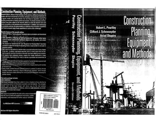
  • 12. , ,'< : -:', " Safety discussions are presented in every chapter covering'machine and formwork use. . .:(;;;"j-'t!~;~ !:1 ~:;;;.1 'I;;:.n; ,,;.'~:'-:';';,~n~,q (::i;<'i;!"~:';l'jtiql:Utit ~.Operatlng,~hd'~or~h:,g ,~ro~I)C;f;;t; ,construction equipmerjfliind ;:",~;l . .trucks is dahgerous.A6~ft~tku ' ." person within 70 ftof the right side of a 150 ton off-highway· truck cannot be seen by the driver. Web-based exercises have been added to m~y chapters to drawattention to the expanding volume of inforina'tion available over the Internet. The computer monitor icon in the text margin will direct you to the text website (www.mhhe.comlpeurifoy7e). In addition, extensive Web resources are provided at the end of every text chapter. For Instructors, a comprehensive Solutions Manual and PowerPoint Lectures, For Students, excellent Additional Resources, including video clips, tied directly to the text. ~r~~!llil~ .,'.For tties~fsarnetl'ac:ibrs;'{ , check.the::t;lade'specificaliQris:",·.... and dete'rmine ~h~width;:?::"'r ; . (length) for both an "Ai'andan'; "S." Calculate the hp per foot of cutting edge ratio for all four conditions. Our website contains additional resources for both instructors and students. C H 1 AJ T 1 E R Machines Make It Possible Construction is the ultimate objective ofa design, and the transfonnation ofa design by construction into a useful structure is accomplished by men and machines. Men and machines transform a project plan into reality,and as machines evolve there is a continuing transfonnation ofhow projects are constructed. This book describes the fundamental concepts ofmachine utilization, which economically match machine capability to specijicproject construction requirements: The efforts ofcontractors and equipment manu- facturers, daring to develop new ideas, constantly push machine capabilities forward. As the array ofuseful equipment expands, the importance ofcareful planning and executionofconstruction operations increases. THE HISTORY OF CONSTRUCTION EQUIPMENT Machines are a vital resource to the accomplishment of a construction project (see Fig. 1.1). One of the most obvious problems in constructing a project is how to transport heavy building materials. Machines provide the solution to that problem. The proof of how well the planner understands the work that must be accomplished and selects appropriate machines for that purpose is revealed by counting the money when the contract is completed. Did the company make a profit or sustain a loss? From the time the firstman decided to build some type of simple structure for protection from the elements through the cpnstruction of the Great Pyra- mids, the Great Wall of China, the temples at Angkor Wat in Cambodia, and continuing until the middle of the nineteenth century, work was accomplished by the muscle of man and beast. When Ferdinand de Lesseps began excavating the Suez Canal in April 1859, corvee laborers, provided by the Egyptian corvee viceroy, did the work of digging that trench in the desert. Human labor Labor required in lieu assisted only by a very few machines continued the work for the next 4 years. oftaxes, 1
  • 13. 2 Construction Planning. Equipment. and Methods FIGURE 1.1 Modern hydraulic excavator loading a truck on a dam project in California. But in 1864 Lesseps and his engineers began turning to machines, and ulti~ ~ately 300 steam-powered mechanical dredges were at work. Those machines; m the final 3 years of the project, excavated the majority of the main canal's 74 miIIi~n cubic meters. Mechanization-machines-transfornled the project and contmue to transform how projects are built. The Dreams The development of construction equipment followed the major changes in tra~sportation modes. When travel and commerce were by water systems, bullders dreamed of machines that would aid in dredging ports, rivers, and c~nals. A~ early as. 1420, th~ Venetian Giovanni Fontana was dreaming and ~lagrammmg dredgmg machmes. Leonardo da Vinci designed such a machine m 1503, and at least one of his machines was actually built but the power source was a lonely runner on a treadmill. On July 4, 1817, at a site near Rome, New York, ground was broken for the 363-mile-long Erie Canal. It was built-excavated-by the efforts of local laborer~ and Irish immigrants, human Jabor. However, by 1852 construction in the UllI.ted States was changing from canal building to railroad construction. The MIddlesex Canal, which connected Boston to the Merrimack River at Lowell, had been in service since 1803, but in 1853 the Boston & Lowell Rail- road superseded it. Nevertheless, construction, be it building canals or rail- roads, was still achieved by the brawn of man and beast. C hap t e r 1 Machines Make It Possible Steam Power Machines William S~ Otis, a civil engineer with the Philadelphia contracting firm of Carmichael & Fairbanks, built the first practical power shovel excavating machine in 1837. The first "Yankee Geologist," as his machines were called, was put to work in 1838 on a railroad project in Massachusetls. The May 10, 1838, issue of the Springfield Republican in Massachusetts reported "Upon the road in the ~astern part of this town, is a specimen of what the Irishmen call 'digging by stame.' For cutting through a sandhill, this steam digging machine must make a great saving of labor." Continued development of the steam shovel was driven by a demand for economical mass excavation machines. In the early 1880s, an era of major con- struction projects began. These projects demanded machines to excavate large quantities of earth and rock. In 1881, Ferdinand de Lessep's French company began work on the Panama Canal. Less than a year earlier, on Deccmber 28, 1880, the Bucyrus Foundry and Manufacturing Company, of BucylUs, Ohio, came into being. Bucyrus became a leading builder of steam shovels (see Fig. 1.2), and 25 years later when the Americans took over the Panama Canal work,- the Bucyrus Company was a major supplier of steam shovels for that effort.:-~~ Still, the most important driver in excavator development was the railroaif' Between 1885 and 1897 approximately 70,000 miles of railway were corr.:~: structed in the United States. William Otis developed his excavator machine FIGURE 1.2 An early twentieth-century steam shovel; note this machine is mounted on steel traction wheels. . 3
  • 14. 4 Construction Planning. Equipment, and Methods because the construction company Cannichael & Fairbanks, which he worked for and in which his uncle Daniel Carmichael was a senior partner, was in the business of building railroads. The Bucyrus Foundry and Manufacturing Company came into being because Dan P. Eells, a bank president in Cleveland, was associated with sev. eral railroads. In 1882 the Ohio Central Railroad gave the new company its first order for a steam shovel, and sales to other railroads soon followed. Internal Combustion Engines By 1890 courts of law in Europe had ruled that Nikolaus Otto's patented four- cycle gasoline engine was too valuable an improvement to keep restricted. Following the removal of that legal restraint, many companies began experi- menting with gasoline-engine-powered carriages. The Best Manufacturing Company (the predecessor to Caterpillar Inc.) demonstrated a gasoline tractor in 1893. The first application of the internal combustion engine to excavating equipment occurred in 1910 when the Monighan Machine Company of Chicago shipped a dragline powered by an Otto engine to the Mulgrew-Boyce Company of Dubuque, Iowa. Henry Harnischfeger brought out a gasoline- engine-powered shovel in 1914. Following World War I, the diesel engine began to appear in excavators. A self-taught mechanic named.C. L. "Clessie" Cummins, working out of an old cereal mill in Columbus, Indiana, developed the Cummins diesel engine in the early 1900s. The Cummins engine soon ,became popular in power shovels. Warren A. Bechtel, who in 1898 entered the construction profession in Oklahoma Territory and quickly built a reputation for successful railroad grading, pioneered the use of motorized trucks, tractors, and diesel-powered shovels in construction. In the winter of 1922-1923, the first gas-powered shovel was brought into the state of Connecticut, and in the spring of 1923, it was employed on a federal-aid road construction project. The third phase of transportation con- struction had begun. Contractors needed equipment for road building. In 1919 Dwight D. Eisenhower, as a young army officer, took an Army convoy cross- country to experience the condition of the nation's roads (see Fig. 1.3). But as the country began to improve its road network, World War II intervened, and road building came to a near halt as the war unfolded. Incubators for Machine Innovation Los Angeles Aqueduct Large construction projects provide a fertile testing ground for equipment innovation. William Mulholland, as Los Angeles. City Engineer, directed an army of 5,000 men for 5 years constructing the Los Angeles Aqueduct that stretches 238 miles from the Owens River to Los Angeles. In 1908 the Holt Manufacturing Company (the other predecessor to Caterpillar Inc.) sold three gas-engine caterpiIIar tractors to the city of Los Angeles for us.e in constructing the Los Angeles Aqueduct. Besides crossing several moun·- tall1 ranges, the aqueduct passed through the Mojave Desert, a severe test site Chapter 1 Machines Make It Possible FIGURE 1.3 Photograph with Eisenhower's description of conditions. Courtesy Dwight D. Eisenhower Library for any machine. The desert and mountains presen~ed a c~allenging test f?r the Holt machines, but Benjamin Holt viewed the entrre project as an expenment and development exercise. . . Holt found that cast-iron gears wore out very qUlckly from sand abraSIOn, so he replaced them with gears made of steel. The ?~tal t~rrai~ broke suspen- sion springs and burned up the two-speed transmiSSions III hiS tractors. The low gear was simply not low enough for climbing th~ mountains. Ho~t made modifications to the tractors both at his factory and m the desert. HIS shop manager, Russell Springer, set up repair facilities in the project work camps. After completion of the project, Mulholland in hjs final report labeled the Holt tractors as the only unsatisfactory purchase that had been made. But Holt had developed a much better machine because of the experience. Boulder Dam In the years between the two world wars, one particular con- struction project stands out because of the equipment contributions that resulted from the undertaking. The Boulder Dam project (later named the Hoover Dam) was an enonnouS proving groun~ for construction equipment and techniques. The use of bolted connections for joining machine pieces together came to an end in the Nevada desert as the project provided the testing ground for R. G. leTourneau's development of welded equipment and cable-operated attachments. LeTourneau, through his numerous innovations in tractor/scraper design, made possible the machines thaUater went to build airfields around the world during World War II. Other developments that came from the Boulder 5
  • 15. 6 torque converter Afluid-type coupling that enables an engine to be somewhat independent ofthe trallsmission. j'.'" .. --"'''" •• :.&~:.r;5?r%~~· ConstructionPtanning. Equipment. and Methods ~am project included sophisticated aggregate production plants, improvements m concrete preparation and placement, and the use of long-flight conveyor sys- tems for material delivery. Three Significant Developments After ~orld War II, road building surged and in 1956 Eisenhower, now presi- dent, signed the legislation that established the interstate highway program. To support the road"building effort, scrapers increased in capacity from 10 to 30 cubic yards (cy). With the development of the torque converter and the p'0~er ,~hi~t transmission, the front-end loader began to displace the old dipper stick shovels. Concrete batch and mixing plants changed from slow manually cont:0lled contraptions to hydraulically operated and electronically controlled eqUipment. But the three most important developments were high- strength steels, nylon cord tires, and high-output diesel engines. 1. High-strength steels. Up to and through World War I1,machine frames had been constructed with steels in the 30,000- to 35,000-psi yield range. After the war, steels in the 40,000- to 45,000-psirange with proportionally better fatigue properties were introduced. The new high-strength steel made possible the production of machines having a greatly reduced overall weight. The weight of a 40-ton off-highway truck body was reduced from 25,000 to 16,000 Ib with no change in body reliability. 2. Nylon cord tires. The utilization of nylon cord material in tire structures made larger tires with increased load capacity and heat resistance a practical reality. Nylon permitted the actual number of plies to be reduced as much as 30% with the same effective carcass strength, but with far less bulk or carcass thickness. This allowed tires to run cooler and achieve better traction, and improved machine productivity. 3. High-output diesel engines. Manufacturers developed new ways to coax greater horsepower from a cubic inch of engine displacement. Compression ratios and engine speeds were raised, and the art of turbo- charging was perfected, resulting in a 10 to 15% increase in flywheel horsepower. .Today there does not appear to be any radically new equipment on the hoozon. However, manufacturers are continually refining the inventions of the past, and the development of new attachments will mean improved utility for t~e .conu:actor's fleet. The future of equipment technology or innovation can be diVided mto three broad categories: • Level ofcontrol: equipment advancements that transfer operational control from the human to the machine. • Amplification ofhuman energy: shift of energy requirements from the man to the machine. • I/1foTl~lation processing: gathering and processing of information by the machme. Chapter 1 Machines Make It Possible The Future A time may come when the base machine is considered only a mobile coun- tenveight with a hydraulic power plant. The base machine will perform a variety of tasks through multiple attachments. This trend has started with hydraulic excavators having many attachments such as hammers, compa~tors, shears, and material-handling equipment. Wheel loaders have seen the mtro- duction of the tool-carrier concept. Wheel loaders are no longer standard bucket machines. There are now other attachments such as brooms, forks, and stingers available so that a loader can perform a multitude of tasks. Other attachments will be developed, offering the contractor more versatility from a base investment. Ultimately, operators sitting in a machine cab may be eliminated altogether. . Safety features and operator station improvements are evolving to com- pensate for the less experienced workforce available today and in the foresee- able·future. Related to workforce quality is the proliferation of supporting machine control technologies. Navigation ofequipment is a broad topic, cover- ing a large spectrum of different technologies and applications. It draws ory;;;;; some very ancient techniques, as well as some of the most advanced in spac'1~:; science and e n g i n e e r i n g . ' " The new field of geospatial engineering is rapidly expanding and a spec~'% trum of technologies is being developed for the purposes of aeronautic naviga- tion, mobile robot navigation, and geodesy. This technology is rapidly being transferred to construction applications. The U.S. Army Corps of Engineers conducted a field test of a Compute~~;; Aided Earthmoving System (CAES) developed by Caterpillar Inc. in 2001 (see~ Fig. 1.4). From that limited test the Corps reported that CAES-equipped CA]"~' 613 s c r a p e r s " • Moved 5.4% more earth in the 20-hr test period. • Reduced preconstruction and restaking time by 28 hrs. • Reduced manpower requirements by 54%.. • Achieved an accuracy of 2.3 in. vertical, 9.6 in. horizontal. The laser and the global positioning system (GPS) guidance will become more common and reduce the need for surveyors. All the grader or dozer oper- ator will need to do is load the digital terrain model into the onboard computer and then guide the machine where the display indicates. Machine position, along with cut or fill information, will be on a screen in front of the operator at all times. This may tum the operator's job into 'I. video game. Ultimately, operators sitting in a machine cab may be eliminated alto- gether. Caterpillar is developing and testing automated rock-hauling units for mining. These units are linked by radio to the office and tracked by GPS. The superintendent need only use a laptop to send the start signal and the trucks do the rest. They leave the lineup at set intervals and follow the prescribed course. The superintendent can track the progress of each machine on the computer. If a truck develops a problem; the situation is signaled to the superintendent for corrective action. 7 '~. ~~~r, 'j.:, GPS A highly precise satellite-based navigation system.
  • 16. 8 Construction Planning. Equipment. and Methods (a) Reference station (b) System mounted on a CAT 613 scraper (c) CAES-equipped scraper working (d) CAES-equlpped scraper working at night FIGURE 1.4 Corps of Engineers field test of a Computer-Aided Earthmoving System. BEING COMPETITIVE This book introduces the engineering fundamentals for planning, selection, and utilization of construction equipment. It enables one to analyze operational problems and to arrive at practical solutions for completing construction tasks. It is about the application of engineering fundamentals and analysis to con- struction activities, and the economic comparison of machine choices. The construction contractor's ability to win contracts and to perform them at a profit is determined by two vital assets: people and equipment. To be eco- nomically competitive, a contractor's equipment must be competitive, both mechanically and technologically. Old machines, which require costly repairs, cannot compete successfully with new equipment having lower repair costs and higher production rates. In most cases, a piece of equipment does not work as a stand-alone unit. Pieces of equipment work in groups. An excavator loads trucks that haul mate- rial to a location on the project where it is required. At that point, the material C hap t er 1 Machines Make II Possible is dumped and a dozer spreads the material. After spreading, a roller compacts the material to the required density. Therefore, a group of machines, in this example an excavator, haul trucks, a dozer, and a roller, constitute what is commonly referred to as an equipment spread. Optimization in the management of an equipment spread is critical for a contractor, both in achieving a competitive pricing position and in accumulating the corporate operating capital required to finance the expansion of project per- formance capability. This book describes the basic operational characteristics of the major heavy construction equipment types. More important, however, it explains the fund~mental concepts of machine utilization, which economically match machine capability to specific project construction requirements. There are no unique solutions to the problem of selecting a machine to work on a particular construction project. All machine selection problems are influenced by external environmental conditions. To appreciate how environ- mental conditions influence the utilization of heavy construction equipment, one must understand the mechanics of how the construction industry operates. THE CONSTRUCTION INDUSTRY By the nature of the product, the construction contractor works under a unique set of production conditions that directly affect equipment. management. Whereas most manufacturing companies have a permanentJactory where raw materials flow in and finished products flow out in a repetitive, assembly-line process, a construction company carries itsfactory with it from job to job. At each new site, the company proceeds to set up and produce a one-of-a-kind project. If the construction work goes as planned, the job will be completed on time and with a profit. Equipment-intensive projects present great financial risk. Many projects involving earthwork are bid on a unit-price basis and there can be large varia- tions between estimated and actual quantities. Some projects require an equip- ment commitment that is greater than the amount that a contractor will be paid for completing the work. Such a situation forces a contractor into a continuing sequence of jobs to support the long-term equipment payments. Additional risk factors facing contractors in equipment-intensive work include financing structure, construction activity levels (the amount of work being put out for bid), labor legislation and agreements, and safety regulations. Project size and outdoor work that is weather dependent contribute to long project durations. Projects requiring two or more years to complete are not uncommon in the industry. • Government-initiated actions that seriously affect the operating environ- ment of the construction contractor are labor legislation and safety regulation. In each of these areas, many regulations impact on a contractor's operations. These actions can directly influence equipment decisions. Legislative acts that exert direct pressure on equipment questions include the Davis-Bacon Act, which is concerned with wage rates, and the Occupational Safety and Health Act (OSHA), which specifies workplace safety requirements. Over one-half of the dollar volume of work in the equipment-intensive fields of construction is 9
  • 17. 10 ., . Construction Planning, Equipment, and Methods subject to wage determinations under the Davis-Bacon Act, and this strongly influences the labor costs incurred by contractors. OSHA, by its rollover protec- tive structures (ROPS) mandate, substantially increased the cost of those pieces of construction equipment that had to have these structures included as part of the basic machine. That particular regulation had a single-point-in-time effect on equipment decisions, much like that resulting from the introduction of new equipment technology. Similarly, there remains the possibility of additional safety requirements. Sound and emissions are issues that are receiving greater regulatory attention. Some owners, by clauses in the construction contract, are limiting machine noise levels. SAFETY The rate of personal injury and death resulting from construction work is too high. Of all major industry classifications, construction has one of the poorest safety records. The construction industry employs nearly 6.4 million people. That is about 6% of the American workforce. However, according to the National Safety Council, the industry has about 23% of the deaths and 10.3% of the injury accidents every year. That translates into 1,150 to 2,000 deaths and 400,000 disabling injuries annually. The Construction Industry Institute estimates the direct andindirect costs of construction accidents may be as high as $17 billion annually. The major causes of deaths and injuries are falls from elevations, electrocution, being struck by equipment, being caught in between equipment, and trench excavation cave-ins. As an industry, we are responsible and accountable for those statistics. It is the responsibility of construction man- agers to create the safety programs that will prevent those accidents. We have both a moral and a business interest in doing so. The key is to provide the leadership, the programs, and the incentives to create a safe industry. . In the late 1960s, Congress began an investigation of construction safety, and in 1970 enacted the Williams-Steiger Act, more commonly referred to as the Occupational Safety and Health Act. The act provided a comprehensive set of safety rules and regulations, inspection procedures, and safety record- keeping requirements. It imposed nationwide safety standards on the construc- tion industry. It also permitted the states to enact their own OSHA legislation as long as the state legislation is at least as stringent as the federal legislation. Employers are required to provide their employees a safe place to work and to maintain extensive safety records. The act also established the Occupational Safety and Health Administra- tion (OSHA), with regional offices in several cities throughout the country. OSHA is responsible for the administration of the legislation and the develop- C hap t e r 1 Machines Make It Possible ment of rules and regulations to implement the act. The OSHA rules and regulations are published in the Federal Register. OSHA Safety and Health Stan- dards, Code of Federal Regulations, Title 29, Part 1910, contains the safety features that must be included in' construction projects by the architect or engineer. COllstruction and Health Regulations, Code of Federal Regulations, Part 1926, pertains specifically to construction contractors and construc- tion work. The act provides both civil and criminal penalties for violations of OSHA regulations. The civil penalty for failure to correct a violation is $7,000 per day with a maximum penalty of $70,000. Criminal penalties can include both fines and imprisonment. It is OSHA's intent to establish a uni- form set of safety standards that apply to construc- tion and to actively enforce those standards. Con- tractors must maintain a current, up-to-date file of OSHA regulations, and work proactively to comply with OSHA requirements (see Figs. 1.5 and 1.6). THE CONTRACTING ENVIRONMENT ~,;o;;{.; Construction contractors work within a unique market situation. The jobW,ans and specifications that are supplied by the client dictate the sales cond.!i~ms and product, but not the price. Almost all work in the equipment-intensive. FIGURE 1.6 Failure to properly suppc;rt thec;ane oufriggers.
  • 18. 12 Construction Planning, Equipment, and Methods fields of construction is awarded on a bid basis, through either open or selec- tive tender procedures. Under the design-bid-build method of contracting, the contractor states a price after estimating the cost based on a completed design supplied by the owner. The offered price includes overhead, project risk con- tingency, and the desired proftt. There is movement toward more design-build contracts, where the con- tractor also has control of the project design. With a design-build project, the contractor must state a guaranteed price before the design is completed. This adds an additional element of risk, because estimating the quantities of materials required to complete the project becomes very subjective. But the advantage to the contractor is that the design can be matched in the most advantageous way to the contractor's construction skills. In either case, it is tacitly assumed that the winning contractor has been able to underbid the competition because of a more efficient work plan, lower overhead costs, or a wiIlingness to accept a lower profit. Not infrequently, however, the range between the high and low bids is much greater than these factors would justify. A primary cause of variance in bids is a contractor's inability to estimate costs accurately. The largest portion of estimating variance is probably not caused by the differences between past and future projects but by a lack of accurate cost records. Most contractors have cost-reporting systems, but in numerous cases the systems fail to allocate expenses to the proper sources, and. therefore cause false conclusions.when used as the historical database for estimating future work. A construction company owner will frequently use both contract volume and contract turnover to measure the strength of the firm. Contract volume refers to the total dollar value of awarded contracts that a firm has on its books (under contract) at any given time; Contract turnover measures the dollar value of work that a firm completes during a specific time interval. Contract volume is a guide to the magnitude of resources a firm has committed at anyone time, as well as to possible profit if the work is completed as estimated. But contract volume fails to answer any timing questions. A contractor, who, with the same contract volume as the competition, is able to achieve a more rapid project completion, and therefore a higher capital turnover rate while maintaining the revenue-to-expense ratio, will be able to increase the ftrm's profits. Contrac- tors who finish work ahead of schedule usually make money. PLANNING EQUIPMENT UTILIZATION Each piece of construction equipment is specifically designed by the manufac- turer to perform certain mechanical operations. The task of the project planner! estimator or the engineer on the job is to match the right machine or combina- tion of machines to the job at hand. Considering individual tasks, the quality of performance is measured by matching the equipment spread's production against its cost. Production is work done; it can be the volume or weight of mate- rial moved, the number of pieces of material cut, the distance traveled, or any sim- ilar measurement of progress. To estimate the equipment component of project Chap te r 1 Machines Make It Possible cost it is necessary to ftrst determine machine productivi~: Productivity is gov- erned ~ engineering fundamentals and management abI~lty. Chapt~r ?covers the principal engineering fundamentals th~t control mach~ne prod~ctlVlty. Each level of productivity has a correspondmg cost assoclated w~th the effo.rt expended. The expenses that a ftrm experiences through m~hme ownershlp and use and the method of analyzing such costs are presented m Chapter 2. Although each major type of equipment has different operational charac- teristics it is not always obvious which machine is best for a particular project task. After studying the plans and specifications, ~isiti~g the project site, and performing a quantity take-off, the plann~r must vlsuahze ?OW to best e~ploy speciftc pieces of equipment to accomphsh the work. Is .It less ex~en~ve to make an excavation with scrapers or to top-load trucks Wlth a draglme. B.oth methods will yield the required end result, but which is the most economical method of attack for the given project conditions? To answer that question the planner develops an initial plan for employ- ment of the scrapers and then calculates their production rate ~d the subse- quent cost. The same process is followed for the top-.load ~peratlOn: .Th~ type of equipment that has the lowest estimated total cost; mcludmg moblhzatlon of the machines to the site, is selected for the job. To perform such analyses, the planner mu.st con~ider bo~ machine capa- bility and methods of employment. In developmg sUltable eqUlp~ent emp~~y­ ment techniques, the planner must have knowledge oithe matenal quanutl~s involved. This book will not cover quantity take-off per se, but that process lS strongly influenced by the equipment and methods ~nder consideration. Ifi~js determined that different equipment and methods Will be used as an excavauon progresses, then it is necessary to divide the quantity take-off in a manner t~at is compatible with the proposed equipment util~z.ation. The person perfo:m~ng the quantity take-off must calculate the qu~tltles so that ~roups. of slmllar materials (dry earth, wet earth, rock) are eaSily accessed. It l~ not Just a~ues­ tion of estimating the total quantity of rock or the total quantlty of mate~al to be excav.ated. All factors, which affect equipment performance and chOIce of construction method such as location of the water table, clay or sand seams, site dimensions, de;th of excavations, and compaction requirements, must be considered in making the quantity take-off. . . The normal operating modes of the particular eqUipment types are dIS- cussed in Chapters 5, 7 to 20, and 22. That presentation, though, should not blind the reader to other possible applications. The most successful construc- tion companies are those that, for each individual project, care!ully study. all possible approaches to the construction proce~s. T~ese compame~ use project preplanning, risk identiftcation, and risk quantlficatlOn techmques m approach- ing their work. No two projects are exactly alike; therefore, it i~ important.that the planner begins each new project with a completely open ~l1ln~ and reviewS all possible options. Additionally, machines are constantly bemg Improved and new equipment being introduced. Heavy equipment is usually classifted or identifted by one of two meth- ods: functional identiftcation or operational identification. A bulldozer, used to 13
  • 19. 14 Construction Planning, Equipment, and Methods push a stockpile of material, could be identified as a support machine for an aggregate production plant, a grouping that could also include front-end loaders. The bulldozer could, however, be functionally classified as an excavator. In this book, combinations of functional and operational groupings are used. The basic purpose is to explain the critical performance characteristics of a particu- lar piece of equipment and then to describe the most common applications for that machine. . ~e efforts of contractors and equipment manufacturers, daring to develop new Ideas, constantly push machine capabilities forward. As the array of use- ful equipment expands, the importance of careful planning and execution of construction operations increases. New machines enable greater economies. It is th: job. of the estima~or and the field personnel to match equipment to proj- ect SituatIOns, and that IS the central focus of this book. SUMMARY Civilizations are built by construction efforts. Each civilization had a construc~ tion industry that fostered its growth and quality of life. This chapter presented an abridged history of construction equipment, an overview of construction work, and the risk associated with bidding work. Machine production, the amount of earth moved or concrete placed, is only one element of the machine selection process. It is also necessary to know the cost associated with that production. The critical learning objective is • An understanding of how construction equipment and machines have been developed in response to the demands of the work to be undertaken. This objective is the basis for the problems that follow. PROBLEMS 1.1 Research these engineers on the Web and write a one-page paper about their accomplishments. William Mulholland Stephen D. Bechtel Sr. Benjamin Holt . R. G. LeTourneau William S. Otis 1.2 Research these engineering accomplishments on the Web and write a one- page paper about the equipment used to accomplish their construction. Hoover Dam Panama Canal Interstate highway program 1.3 What is the function of the Occupational Health and Safety Administration? What OSHA office administers your area? Chapter 1 Machines Make It Possible 1.4 Why do some construction workers resist the use of safety equipment sNch as hard hats and fall protection harnesses? Why does the practice of resistingthe use of safety equipment persist? What should be done about it? REFERENCES 1. Buildingfor Tomorrow: Global Enterprise and the U.S. Construction Industry (1988). National Research Council, National Academy Press, Washington, DC. 2. Davis.Baco/l Manual OIl Labor Standardsfor Federal and Federally Assisted Construction (1993). The Associated General Contractors (AGC) of America, Alexandr~a, VA. 3. OSHA Safety & Health Standards for Construction (OSHA 29 CFR 1926 Construction Industry Standards) (2003). The Associated General Contractors (AGC) of America, Alexandria, VA. 4. Schexnayder, Cliff J., and Scott A. David (2002). "Past and Future of Construction Equipment," Joumal ofConstruction Engineering lind Management, ASCE, 128(4), pp. 279-286. WEBSITE RESOURCES Significant additional information about the construction industry can be found posted on the following websites. Associations and Organizations Sites about construction associations and organizations include 1. www.asce.org The American Society of Civil Engineers (ASCE) is a professional organization of individual members from all disciplines of civil engineering dedicated to developing leadership, advancing technology, advocating lifelong learning, and promoting the profession. 2. www.asme.org The American Society of Mechanical Engineers (ASME) is a nonprofit educational and technical organization that publishes many standards in reference to construction equipment. 3. www.agc.org The Associated Geneml Contractors of America (AGC) is an organization ofconstruction contractors and industry-related companies. 4. construction-institute.org The Construction Industry Institute (CII) is a research organization with the mission of improving the competitiveness of the construction industry. CII is a consortium of owners and contractors who have joined together to find better ways of planning and executing,capital construction programs. Codes and Regulations Sites that provide information about codes or regulations that impact the construction industry include 1. www.osha.gov The U.S. Department of Labor, Occupational Labor Safcty and Health Administration (OSHA) establishes protcctive standards, enforces those standards, and reaches out to employers and employees through technical
  • 20. Construction Planning, Equipment, and Methods assistance and consultation programs. OSHA's mission i, to ensure safe and healthful workplaces in America. 2. www.nist.gov/weIcome.html The National Institute of Standards (NIST) is a non- regulatory federal agency within the U.S. Commerce Department's Technology Administration. NIST develops and promotes measurement, standards, and : technology. 3. www.ansi.org The American National Standards Institute (ANSI) is a private, nonprofit organization that administers and coordinates the U.S. voluntary standardization and conformity assessment system. 4. www.iso.ch The International Organization for Standardization (ISO) is a non- governmental organization. It is a network ofthe national standards institutes from 148 countries, with one member per country and a Central Secretariat in Geneva, Switzerland, that coordinates the system. S. www.astm.org The ASTM International, formerly known as the American Society for Testing and Materials, is a not-for-profit organization that provides a global forum for the development and publication ofvoluntary consensus standards for materials, products, systems, and services. Safety 1. www.nsc.org National Safety Council. Excellent library for workplace safety- consultants and human resources managers offering resources, member information, services, and publications. 2. www.construction-institute.org Home page ofthe Construction Industry Institute, University ofTexas at Austin. Source of construction management research relating to best practices. 3_ www.osha.gov Occupational Safety and Health Administration site. Includes news, statistics, publications, regUlations, standards, and reference resources. 4. www.ntsb.govNationaITransportationSafetyBoard.This independent federal agency conducts investigations on significant transportation accidents, and offers synopses and public hearing overviews. S. www.crmusa.com Contractors Risk Management. Explore details of this company offering manuals, customized plans, and training programs for construction industry safety and health guidelines. 6. www.agc.org Associated General Contractors of America. Deals with contracting and safety issues and construction laws. C H E R Fundamental Concepts of Equipment Economics A correct and complete understanding ofthe costs that result from equipment ownership and operation provide companies a market advantage that leads to greater profits. Ownership cost is the cumulative result ofthose cash flows an owner experiences whether or not the machine is productively employed on a project. Operating cost is the sum ofthose expenses an owner experiences by working a machine on a project. The process ofselecting a particular type ofmachine for use in constructing a project requires knowledge ofthe cost associated with operating the machine in the field. There are three basic methods for securing a particular machine to use on a project: (1) buy, (2) rent, or (3) lease. IMPORTANT QUESTIONS Equipment cost is often one of a contractor's largest expense categories, and it is a cost fraught with variables and questions. To be successful, equipment Owners must carefully analyze and answer two separate cost questions about their machines: 1. How much does it cost to operate the machine on a project? 2. What is the optimum economic life and the optimum manner to secure a machine? . The first question is critical to bidding and operations planning. The only reason for purchasing equipment is to perform work that Will generate a profit for the company. This question seeks to identify the expense ass~ciated with productive machine work, and is commonly referred to as ownership and oper- ating (0&0) cost. 0&0 cost is expressed in dollars per machine operating hour (e.g., $90/hr for a dozer) because it is used in calculating the cost per unit
  • 21. 18 Construction Planning, Equipment, and Methods of machine production. If a dozer can push 300 cy per hour and it has a $90/hr 0&0 cost, production cost is $0.300!cy ($90/hr + 300 cy/hr). The estimator! planner can use the cost per cubic yard figure directly on unit price work. On a lump-sum job, it will be necessary to multiply the cost/unit price by the esti- mated quantity to obtain the total amount that should be charged. The second question seeks to identify the optimum point in time to replace a machine and the optimum way to secure a machine. This is important in that it will affect 0&0 cost and can lower production expense, enabling a contrac- tor to achieve a better pricing position. The process of answering this question is known as replacement analysis. A complete replacement analysis must also investigate the cost of renting or leasing a machine. The economic analyses that answer these two cost questions require the input of many expense and operational factors. These input factors will be dis- cussed first and a development of the analysis procedures follows, EQUIPMENT RECORDS Data on both machine utilization and costs are the keys to making rational equipment decisions, but the collection of individual pieces of data is only the first step. The data must be assembled and presented in usable formats. Marly contractors recognize this need and strive to collect and maintain accurate equipment records for evaluating machine performance, establishing operating cost, analyzing replacement questions, and managing projects. Surveys of industrywide practices, however, indicate that such efforts are not universal. Realizing the advantages to be gained therefrom, owners are directing more attention to accurate record keeping. Advances in computer technology have reduced the effort required to implement record systems. Computer com- panies offer record-keeping packages specifically designed for contractors. In many cases, the task is simply the retrieval of equipment cost data from exist- ing accounting files. Automation introduces the ability to handle more data economically and in shorter time frames, but the basic information required to make rational deci- sions is still the critical item. A commonly used technique in equipment cost- ing and record keeping is the standard rate approach. Under such a system, jobs are charged a standard machine utilization rate for every hour the equip- ment is employed. Machine expenses are charged either directly to the piece of equipment or to separate equipment cost accounts. This method is sometimes referred to as an internal or company rental system. Such a system usually presents a fairly accurate representation of investment consumption and it properly assigns machines expenses. In the case of a company replacing machines each year and continuing in operation, this system enables a check at the end of each year on estimate rental rates as the internally generated rent should equal the expenses absorbed. The first piece of information necessary for rational equipment analysis is not an expense but a record of the machine's use. One of the implicit assump- tions of a replacement analysis is that there is a continuing need for a ---~~~ - - - Chapter 2 Fundamental Concepts of Equipment Economics machine'sproduction capability. Therefore, before beginning a replacement analyss, the disposal-replacement question must be resolved. Is this machine really necessary? A projection of the ratio between total equipment capacity and utilized capacity provides a quick guide for the dispose-replace question. The level of detail for reporting equipment use varies. Both independent service vendors and equipment companies (DeereTrax offered by John Deere and Product Link offered by Caterpillar being two examples) offer data collec- tion devices that provide accurate real-time information about machine use. These devices are installed in the machine and transmit data via the most cost- effective wireless network (satellite or cellular networks). As a minimum, data should be collected on a daily basis to record whether a machine worked or was idle. A more sophisticated system will seek to identify use on an hourly basis, accounting for actual production time and categorizing idle time by clas- sifications such as standby, down weather, and down repair. The input for either type of system is easily incorporated into regular personnel timekeeping reports, with machine time and operator time being reported together. Most of the information required for ownership and operating or replace- ment analyses is available in the company's accounting records. All owners keep records on a machine's initial purchase expense and final realiz~%'}al­ vage value as part of the accounting data required for tax filings. Mfimte- nance expenses can be tracked from mechanics' time sheets, purchase orders for parts, or from shop work orders. Service logs provide information con- cerning consumption of consumables. Fuel amounts can be recorded at fuel points or with automated systems. Fuel amounts should be cross-checked against the total amount purchased. When detailed and correct reportintc'pro- cedures are maintained, the accuracy of equipment costs analyses is g~atly enhanced."~ THE RENT PAID FOR THE USE OF MONEY What is commonly referred to as the time value of money is the difference-- rent-that must be paid if one borrows some money for use today and returns the money at some future date. Many take this charge for granted, as the pro- liferation of credit cards testifies. This rent or added charge is termed interest. It is the profit and risk that the lender applies to the base amount of money that is borrowed. Interest, usually expressed as a percentage of the amount bor- rowed (owed), becomes due and payable at the close of each billing time period. It is' typically stated as a yearly rate. As an example, if $1,000 is bor- rowed at 8% interest, then $1,000 x 0.08, or $80, in interest plus the original $1,000 is owed after 1 year (yr). Therefore, the borrower would have to repay $1,080 at the end of a 1-yr time period. If this new total amount is not repaid at. the end of the 1-yr period, the interest for the second year would be calculated based on the new total amount, $1,080, and thus the interest is com- pounded. Then, after a 2-yr period, the amount owed would be $1,080 + ($1,080 X 0.08), or $1,166.40; If the company's credit is good and it has bor- rowed the $1,000 from a bank, the banker normally does not care whether
  • 22. 20 . Construction Planning, Equipment, and Methods repayment is madeafter I yr at $1,080 or after 2 yr at $1,166.40. To the bank the three amounts, $1,000, $1,080, and $1,166.40, a:,:'e equivalent. In other words, $1,000 today is equivalent to $1,080 1 yr in the future, which is also equivalent to $1,166.40 2 yr in the future. The three amounts are obviously not equal; they are equivalent. Note that the concept oj equivalence involves: time and a specific rate oj interest. The three amounts are equivalent only for the case of an interest rate of 8%, and then only at the specified points in time. Equivalence means that one sum or series differs from another only by the accrued, accumulated interest at rate i for nperiods of time. Note that in the example the principal amount was multiplied by an inter- est rate to obtain the amount of interest due. To generalize this concept, the following symbols are used: P = a present single amount of money F = a future single amount of money, after n periods of time i = the rate of interest per period of time (usually 1 yr) n =the number of time periods Different situations involving an interest rate and time are presented next, and the appropriate analytical formulas are developed. Equation for Single Payments To calculate the future value F of a single payment P after n periods at an interest rate i, these formulations are used: At the end of the first period, n = 1: FJ =P + Pi At the end of the second period, n = 2: At the end of the nth period: F2 =P + Pi + (P + Pi)i =P(l + i)2 F =P(1 +i)n Or the future single amount of a present single amount is F= P(l + on [2.1] Note that F is related to P by a factor that depends only on i and n. This factor is termed the single payment compound amount Jactor (SPCAF); it makes F equivalent to P. If a future amount F is given, the present amount P can be calculated by transposing the equation to P = F (1 + i)" [2.2] The factor 1/(1 + i)" is known as the present worth compound amountJactor (PWCAF). C hap t er 2 Fundamental Concepts of Equipment Economics ~ A constructor wishes to borrow $12,000 to finance a project. The interest rate is 5% per year. If the borrowed amount and the interest are paid back after 3 yr, what will be the total amount of the repayment? To solve, use Eq. [2.1) F =$12,000 (1 + 0.05)3 = $12,000 (1.157625) =$13,891,50 The amount of interest is $1,891.50 A constructor wants to set aside enough money today in an interest-bearing account to have $100,000 5 yr from now for the purchase of a replacement piece of equipment. If the company can receive 8% per year on its investment, how much should be set aside now to accrue the $100,000 5 yr from now? To solve, use Eq. [2.2) p = $100,000 (1 + 0.08)5 = $68,058.32 $100,000 (1.469328) In Examples 2.1 and 2.2 single payments now and in the future were equated. Four parameters were involved: P, F, i, and n. Given any three parameters, the Jourth can easily be calculated. Formulas for a Uniform Series of Payments Often payments or receipts occur at regular intervals, and such uniform values can be handled by use of additional formulas. First, let us define another symbol: A = uniform end-oj-period payments or receipts continuing for a duration of n periods If this uniform amount A is invested at the end of each period for n periods at a rate of interest i per period, then the totaI" equivalent amount F at the end of the 11 periods will be F = A[(1 + i),,-1 + (1 + i),,-2 + ... + (1 + i) + 1) By multiplying both sides of the equation by (I + i) we obtain F(1 + i) =A[(I + it + (1 + i)n-J + (1 + i),,-2 + ... + (I + i)] 2 "tUlO"j· 'J¥W4H'"
  • 23. 22 Construction Planning. Equipment. and Methods Now by subtracting the original equation from both sides of the new equation we obtain ' which can be rearranged to Fi = A(1 + on - 1 [ (1 + i)n - 1] F=A i [2.3] The relationship [(1 + i)n - 1]1i is known as the unifonn series, com- pound amountfactor (USCAF). The relationship can be rearranged to yield A~ F[ (1 + :)n - 1] [2.4] The relationship i/[(1 + i)n - I] is known as the unifonn series sinking fu1ld factor (USSFF) because it determines the uniform end-of-period invest- ment A that must be made to provide an amount F at the end of n periods. To determine the equivalent uniform period series required to replace a present value of P, simply substitute Eq. [2.1] for F into Eq. [2.4] and rearrange. The resulting equation is P = A[..:..(I_+--..:.i)_n-_1] . i(1 + i)n [2.5] This relationship is known as the unifonn series present worthfactor (USPWF). By inverting Eq. [2.5] the equivalent uniform series end-of-period value A can be obtained from a present value P. The equation is A =P ---.:~-!-- [ i(1 + nn ] (1 + i)n - 1 [2.6] This relationship is known as the unifonn series capital recovery factor (USCRF). As .an aid to unde~standing the six preceding equivalence relationships, ~ppropnate cash flow diagrams can be drawn. Cash flow diagrams are draw- mgs where the horizontal line represents time and the vertical arrows represent cash flows at specific times (up positive, down negative). The cash flow dia- gra~s for each relationship are shown in Fig. 2.1. These relationships form the baSIS for many complicated engineering economy studies involving the time value of money, and many texts specifically address this subject. Most engineering economy problems are more complicated than the exam- ples we have co~si~ered and must be broken down into parts. Example 2.3 Illustrates how thIS IS done and demonstrates the use of the other equivalency relationships. Chapter 2 Fundamental Concepts of Equipment Economics F F= P(l+i)" or P= F~lli~ P o A A A A A A A A P=A!<:l+i)"-ll or A= p,-i(l +i)"l [i(l+i)"J l{1+i)"-U p FIGURE 2.1 Cash flow diagrams. A machine cost $45,000 to purchase. Fuel, oil, grease (FOG), and minor mainte- nance are estimated to cost $12.34 per operating hour (those hours when the engine is operating and the machine is doing work). A set of tires cost $3,200 to replace, and their estimated life is 2,800 use hours. A $6,000 major repair will probably be required after 4,200 hr of use. The machine is expected to last for 8,400 hr, after which it will be sold at a price (salvage value) equal to 10% of the original purchase price. A final set of new tires will not be purchased before the sale. How much should the owner of the machine charge per hour of use, if it is expected that the machine will operate 1,400 hr per year? The company's cost of capital rate is 7%. First solve for n, the life 8,400 hr 6 n = 1,400 hr per yr = yr Usually ownership and operating cost components are calculated separately. Tires are considered an operating cost element because they wear out much faster than ~ ~,
  • 24. 24 - - --- - - - - - - Construction Planning, Equipment, and Methods the basic machine. Therefore, before calculating the ownership cost of a machine having pneumatic tires, the cost of the tires should be subtracted from the pur- chase price. $45,000 - $3,200 = $41,800 Now the annualized purchase expense can be calculated using the uniform series capital recovery factor: [ 0,07(1 +0.07)6] Aawnership == $41,800 (1 + 0.07)6 _ 1 = $41,800 X 0.209796 =$8,769.46 Salvage value at the end of 6 yr is . $45,000 x 0.1 = $4,500 The annualized value of the salvage amount 6 yr in the future can be calculated using the uniform series sinking fund factor: Asalvage = $4,500L1 + ~~:)6 _ 1] = $4,500 X 0.139796 = $629.08 The annualized value of the salvage amount 6 yr in the future can also be calcu- lated using the present worth compound amount factor with the uniform series capital recovery factor: [ $4,500 ] [0.07(1 + 0.07)6] Asalvage = (1 + 0.07)6 (1 + 0.07)6 _ 1 = $629.08 The annual FOG and minor maintenance cost is $12.34 per hr X 1,400 hr per yr = $17,276.00 In addition to the original set of tires, two sets of replacement tires will have to be purchased, one set 2 yr into the life of the machine and a second set 4 yr into the life. To annualize the tire replacement cost, these future-point-in-time costs must be made equivalent to a present amount at time zero, and then the resulting amount is annualized across the 6-yr life of the machine. To do this, use the pres- ent worth compound amount factor with the uniform series capital recovery factor: [ $3,200 $3,200] [0.07(1 + 0.07)6] A tires = $3,200 + (1 + 0.07)2 + (1 + 0.07)4 (1 + 0.07)6 - 1 = ($3,200.00 + $2,795.00 + 2,441.26)(0.209796) = $1,769.89 The annualized cost for the major repair 3 yr into the life is [ $6,000 ] [0.07(1 + 0.07)6] AmajOrrepair = (1 + 0.07)3 (1 + 0.07)6 - 1 = ($4,897.79)(0.209796) = $1,027.54 Chapter 2 Fundamental Concepts of Equipment Economics The resulting total annual cost is At~tal = $8,769.46 - $629.08 + $17,276.00 + $1,769.89 + $1,027.54 = $28,213.81 The total cost per hour is $28,213.81 per yr _ $20 153 h Total cost = 1,400 hr per yr - . per r COST OF CAPITAL 'rheinterest rate a company experiences is really a weighted average rate resulting from the combined cost as~ociated ~ith all external and int~rnal sources of capital funds-debt (borrowmg), eqUIty (sale of stock), ~d r~tamed earnings (internally generated funds). Furtherm~re, the ~ost-of-~ap~tal mt~rest rate a company experiences is affected by th~ nsk assoclat~d WIth Its busm~ss type. The market perceives the risk of the busmess and apphes an after-tax dIS- count rate to the future wealth it expects to derive from the firm. Therefore, the rate that banks charge for borrowed funds cannot betaken alone as the company's cost-of-capital interest rate when evaluating investment alterna- tives. For a complete treatment of cost of capital, see Modigliani and Miller's classic paper published in The American Economic Review [5]. Many discussions of equipment·economics include interest as a cost of ownership. Sometimes the authors make comparisons with the interest rates that banks charge for borrowed funds or with the rate that could be earned if the funds were invested elsewhere. Such comparisons imply that these are appropriate rates to use in an equipment cost analysis. A few authors appear to have perceived the proper character of interest by realizing that a company requires capital funds for all of its operations. It is not logical to assign differ- ent interest costs to machines purchased wholly with retained earnings (cash) as opposed to those purchased with borrowed funds. A single interest rate should be determined by examination of the combined costs associated with all sources of capital funds: debt, equity, and retained earnings. There are two parts to the common misunderstanding concerning the proper way to account for interest. First, as just discussed, the correct interest rate should reflect the combined effect of the costs associated with all capital funds. The second error comes in trying to recoup interest costs. Interest is not a cost to be added together with purchase expense, taxes, and insurance when calculating the total cost of a machine. ... . . . This might be easier to understand using an analogy. Conslde~ the situatIon of a banker trying to decide if a loan should be granted. The questIOn before the banker is one of risk: what are the chances the money will be repaid? Based on the perceived risk, a decision is made on how much return must be received to balance the risk. If a hundred loans are made, the banker knows some will not be repaid. Those borrowers who repay their loans as promised have to provide the total profit margin for the bank. The good loans must carry the bad loans. A 25 ,. c :;. f
  • 25. 26 '*'V,IOI'.' Construction Planning, Equipment, and Methods company utilizing equipment should be making a similar analysis every time a decision is made to invest in a piece of equipment. Based on the risk of the construction business, interest is the fulcrum for determining if the value a machine will create for the company is sufficient. The proper interest rate will ensure that this ratio of gain in value to cost is correctly accounted for in the decision process. The interest rate at issue is referred to in the economic literature as the cost of capital to the company and a market value technique has been developed for its calculation. A complete development of the market value cost-of-capital calculation is beyond the scope of this text, but Reference 4 at the end this chapter is a good presentation of the subject. The resulting cost- of-capital rate is the correct interest rate to use in economic analyses of equipment decisions. EVALUATING INVESTMENT ALTERNATIVES The purchase, rental, or.replacement of a piece of equipment is a financial investment decision, and as such the real question is how best to use a com- pany's assets. Financial investment decisions are analyzed using time value of money principles. Such analyses require an input interest rate or the calcula- tion of the interest rate that results from the assumed cash flows. . Discounted-Present-Worth Analysis A discounted-present-worth analysis involves calculating the equivalent pres- ent worth or present value of all the dollar amounts involved in each of the individual alternates to determine the present worth of the proposed alternates. The present worth is discounted at a predetermined rate of interest i, often termed the minimum attractive rate of return (MARR). The MARR is usually equal to the current cost-ofcapital rate for the company. Example 2.4 illus- trates the use of a discounted-present-worth analysis to evaluate three mutually exclusive investment alternatives. Ace Builders is considering three different acquisition methods for obtaining pickup ~ trucks. The alternatives are PIiICS A. Immediate cash purchase the trucks for $16,800 each, and after 4 yr sell each truck for an estimated $5,000. B. Lease the trucks for 4 yr for $4,100 per year paid in advance at the begin- ning of each year. The contractor pays all operating and maintenance costs for the trucks, and the leasing company retains ownership. C. Purchase the trucks using a time payment plan requiring an immediate down payment of $4,000 and $4,500 per year at the end of each year for 3 yr. Assume the trucks will be sold after 4 yr for $5,000 each. Chap t er 2 Fundamental Concepts of Equipment Economics If the contractor's MARR is 8%, which alternative should be used? To solve, calcu- late the net present worth (NPW) of each alternative using an 8% interest rate and select the least costly alternative. For the Aalternative, use the present worth compound amount factor to calcu- late the equivalent salvage value at time zero. Add the purchase price, which is negative because it is a cash outflow, and the equivalent salvage value, which is positive because it is a cash inflow. The result is the net present worth of alternative A: $5,000 NPWA = -$16,800 + PWCAF Calculating the PWCAF with i equal to 8% and n equal to 4, $5000 NPWA = -$16,800 + 1.3~0489 = -$13,124.85 For alternative B, use the uniform series present worth factor to calculate the time-zero equivalent value of the future lease payments, and add to that result'the value of the initial lease payment; both of these are negative because thei'are cash outflows. There is no salvage in this case, as the leasing company retains. ownership of the trucks. NPWa = -$4,100 - $4,100 (USPWF) Calculating the USPWF with i equal to 8% and nequal to 4, ( 0.259712] NPWa = -$4,100 - $4,100 0.100777 = -$14,666.10 For alternative C use the uniform series present worth factor to calculate the time-zero equivalent value of the future payments and the present worth compound amount factor to calculate the equivalent salvage value at time zero. Add the three values, the initial payment and the equivalent annual payment both being negative and the salvage being positive, to arrive at the net present worth of alternate C. [ $5,000 ] NPWc = -$4,000 - $4,500 (USPWF) + PWCAF [ 0.259712] [$5,000] NPWc ::;: -$4,000 - $4,500 0.100777 + 1.360489 = -$11,921.79 The least costly alternative is C. Example 2.4 was simplified in two respects. First, the number of calcula- tions required was quite small. Second, all three alternatives involved the same time duration (4-yr lives in the example). Problems involving more data may require more calculations, but the analysis approach is the same as shown in Example 2.th When the alternatives involve different time durations (machines
  • 26. 28 Construction Planning, Equipment, and Methods have different expected durations of usefulness), the analysis must be modified to account for the different time dUrations. Obviously, if a comparison is made of one .alte~ative having a life of 5 yr and another with a life of 10 yr, the respectIve discounted present worths are not directly comparable. How is such a situation handled? There are two approaches that are generally used. Approach 1. Truncate (cut off) the longer-lived alternative(s) to equal the shorter-lived alternative and assume a salvage value for the unused portion of the longer-lived alternative(s). Then make the comparison on the basis ofequal lives. Approach 2. Compute the discounted present worth on the basis of the least common denominator of the different alternatives' lives. ELEMENTS OF OWNERSHIP COST Ownership cost is the cumulative result of those cash flows an owner experi- ences whether or not the machine is productively employed on a job. It is a cost related to finance and accounting exclusively, and it does not include the wrenc?es, nuts and bolts, and consumables necessary to keep the machine operatmg. ' . Most of ownership cash flows are expenses (outflows), but a few are cash mflows. The most significant cash flows affecting ownership cost are 1. Purchase expense 2. Salvage value 3. Tax saving from depreciation 4. Major repairs and overhauls 5. Property taxes 6. Insurance' 7. Storage and miscellaneous Purchase Expense The cash outflow the firm experiences in acquiring ownership of a machine is the purchase expense. It is the total delivered cost (drive-away cost), including amounts for all options, shipping, and taxes, less the cost of tires if the machine has pneumatic tires. The machine will show as an asset in the firm's accounting records. The firm has exchanged money (dollars), a liquid asset, for a machine, a fixed asset with which the company hopes to generate profit. As the machine is used on projects, wear takes its toll and the machine can be thought of as being used up or consumed. This consumption reduces the machine's value because the revenue stream it can generate is likewise re~uced. Normally, ?n owner t;ies to account for the decrease in value by pro- rat~ng the consumptIOn of the Investment over the service life of the machine. ThIS prorating is known as depreciation. Chapter 2 Fundamental Concepts of Equipment Economics It can be argued that the amount that should be prorated is the difference betweenlthe initial acquisition expense and the expected future salvage value. Such a statement is correct to the extent of accounting for the amounts involved, but it neglects the timing of the cash flows. Therefore, it is recom- mended that each cash flow be treated separately to allow for a time value analysis and to allow for ease in changing assumptions during sensitivity analyses. Salvage Value Salvage value is the cash inflow a firm receives if a machine still has value at the time of its disposal. This revenue will occur at a future date. Used equipment prices are difficult to predict. Machine condition (see Fig. 2.2), the movement of new machine prices (see Fig. 2.3), and the machine's possible secondary service applications affect the amount an owner can expect to receive. A machine having a diverse and layered service potential will com- mand a higher resale value. Medium-size dozers, which often exhibit rising salvage values in later years, can have as many as seven different levels of useful life. These may range from an initial assignment as a high-production machine on a dirt spread to an infrequent land-clearing assignment by a fariner. Historical resale data can provide some guidance in making salvage value predictions and can be fairly easily accessed from auction price books. By studying such historical data and recognizing the effects of the economic envi- ronment, the magnitude of salvage'value prediction errors can be minimized and the accuracy of an ownership cost analysis improved. FIGURE 2.2 Salvage value is dependent on machine condition. 29
  • 27. [ - - - - 30 Construction Planning. Equipment. and Methods $175.000 I--- Cost of new machine. replaceme~ I---~ I--- ~ - $165.000 "" Original price current machine "-t-... r---r-..... $155,000 ...... t--- Salvage value current machine t-- $145,000 $135,000 2 3 4 5 6 7 Year FIGURE 2.3 The movement of new machine prices -cost- is one factor affecting salvage value. Tax Savings from Depreciation The tax savings from depreciation are a phenomenon of the tax system in the United States. (This may not be an ownership cost factor under the tax laws in other countries.) Under the tax laws of the United States, depreciating a machine's loss in value with age will lessen the net cost of machine ownership.' The cost saving, the prevention of a cash outflow, afforded by tax depreciation' is a result of shielding the company from taxes. This is an applicable cash flow factor only if a company is operating at a profit. There are carry-back features in the tax law so that the saving can be preserved even though there is a loss in anyone particular year, but the long-term operating position of the company must be at a profit for tax saving from depreciation to come into effect. The rates at which a company can depreciate a machine are set by the rev- enue code. These rates usually have no relation to actual consumption of the asset (machine). Therefore, many companies keep several sets of depreciation numbers, one for depreciation tax purposes, one for corporate earnings tax accounting purposes, and one for internal and/or financial statement purposes. The first two are required by the revenue code. The last tries to accurately match the consumption of the asset based on work application and company maintenance policies. Under the current tax laws, tax depreciation accounting no longer requires the assumption of a machine's future salvage value and useful life. The only piece of information necessary is basis. Basis refers to the cost of the machine for purposes of computing gain or loss. Basis is essential. To compute tax depreciation amounts, fixed percentages are applied to unadjusted basis. The terminology adjusted/unadjusted refers to changing the book value of a machine by depreciation. Chap t er 2 Fundamental Concepts of Equipment Economics The tax law allows the postponement of taxation on gains derived from the exchange of like-kind depreciable property. If there is a gain realized from a like-kind exchange, the depreciation basis of the new machine is reduced by the amount of the gain. However, if the exchange involves a disposal sale to a third party and a separate acquisition of the replacement, the gain from the sale is taxed as ordinary income. A tractor with an adjusted basis (from depreciation) of $25,000 is traded for a new tractor that has a fair market value of $400,000. A cash payment of $325,000 is made to complete the transaction. Such a transaction is a nontaxable exchange and no gain is recognized on the trade-in. The unadjusted basis of the new tractor is $350,000, even though the cash payment was $325,000 and the apparent gain in value for the traded machine was $50,000 [($400,OOO - $325,000) - $25,000]. Cash payment $325,000 Adjusted basis of the trade-in tractor 25,000 Basis of the new tractor $350,000 If the owner had sold the old tractor toa third party for $75,000 and then pbr- chased a new tractor for $400,000, the $50,000 profit on the third-party sale wOOd have been taxed as ordinary income and the unadjusted basis of the new tractor would be $400,000. The current tax depreciation law es'tablishes depreciation percentages t,bat can be used based on the specific year of machine life. These are usuallyJl:1e optimum depreciation rates in terms of tax advantages. However, an owner can still utilize the straight-line method of depreciation or methods that are not expressed in terms of time duration (years). Unit-of-production would be an example of a depreciation system that is not time based. Straight-Line Depreciation Straight-line depreciation is easy to calculate. The annual amount of depreciation Dn, for any year n, is a constant value, and thus the book value (BVn) decreases at a uniform rate over the useful life of the machine. The equations are 1 Depreciation rate, Rn == N where N = number of years. Annual depreciation amount, Dn =Unadjusted basis X Rn Substituting Eq. [2.7] yields [2.7] Unadjusted basis Dn = N [2.8] Book value year m, BVn' =Unadjusted basis - (n X Dn) [2.9]